EP4021357B1 - Adjustment means for a mandibular advancement device - Google Patents
Adjustment means for a mandibular advancement device Download PDFInfo
- Publication number
- EP4021357B1 EP4021357B1 EP20857115.8A EP20857115A EP4021357B1 EP 4021357 B1 EP4021357 B1 EP 4021357B1 EP 20857115 A EP20857115 A EP 20857115A EP 4021357 B1 EP4021357 B1 EP 4021357B1
- Authority
- EP
- European Patent Office
- Prior art keywords
- arm
- lower plate
- mandibular advancement
- screw
- body portion
- Prior art date
- Legal status (The legal status is an assumption and is not a legal conclusion. Google has not performed a legal analysis and makes no representation as to the accuracy of the status listed.)
- Active
Links
Images






Classifications
-
- A—HUMAN NECESSITIES
- A61—MEDICAL OR VETERINARY SCIENCE; HYGIENE
- A61F—FILTERS IMPLANTABLE INTO BLOOD VESSELS; PROSTHESES; DEVICES PROVIDING PATENCY TO, OR PREVENTING COLLAPSING OF, TUBULAR STRUCTURES OF THE BODY, e.g. STENTS; ORTHOPAEDIC, NURSING OR CONTRACEPTIVE DEVICES; FOMENTATION; TREATMENT OR PROTECTION OF EYES OR EARS; BANDAGES, DRESSINGS OR ABSORBENT PADS; FIRST-AID KITS
- A61F5/00—Orthopaedic methods or devices for non-surgical treatment of bones or joints; Nursing devices ; Anti-rape devices
- A61F5/56—Devices for preventing snoring
-
- A—HUMAN NECESSITIES
- A61—MEDICAL OR VETERINARY SCIENCE; HYGIENE
- A61C—DENTISTRY; APPARATUS OR METHODS FOR ORAL OR DENTAL HYGIENE
- A61C7/00—Orthodontics, i.e. obtaining or maintaining the desired position of teeth, e.g. by straightening, evening, regulating, separating, or by correcting malocclusions
- A61C7/08—Mouthpiece-type retainers or positioners, e.g. for both the lower and upper arch
-
- A—HUMAN NECESSITIES
- A61—MEDICAL OR VETERINARY SCIENCE; HYGIENE
- A61B—DIAGNOSIS; SURGERY; IDENTIFICATION
- A61B5/00—Measuring for diagnostic purposes; Identification of persons
- A61B5/0002—Remote monitoring of patients using telemetry, e.g. transmission of vital signals via a communication network
- A61B5/0015—Remote monitoring of patients using telemetry, e.g. transmission of vital signals via a communication network characterised by features of the telemetry system
- A61B5/0022—Monitoring a patient using a global network, e.g. telephone networks, internet
-
- A—HUMAN NECESSITIES
- A61—MEDICAL OR VETERINARY SCIENCE; HYGIENE
- A61B—DIAGNOSIS; SURGERY; IDENTIFICATION
- A61B5/00—Measuring for diagnostic purposes; Identification of persons
- A61B5/48—Other medical applications
- A61B5/4806—Sleep evaluation
- A61B5/4818—Sleep apnoea
-
- A—HUMAN NECESSITIES
- A61—MEDICAL OR VETERINARY SCIENCE; HYGIENE
- A61C—DENTISTRY; APPARATUS OR METHODS FOR ORAL OR DENTAL HYGIENE
- A61C7/00—Orthodontics, i.e. obtaining or maintaining the desired position of teeth, e.g. by straightening, evening, regulating, separating, or by correcting malocclusions
- A61C7/06—Extra-oral force transmitting means, i.e. means worn externally of the mouth and placing a member in the mouth under tension
-
- A—HUMAN NECESSITIES
- A61—MEDICAL OR VETERINARY SCIENCE; HYGIENE
- A61C—DENTISTRY; APPARATUS OR METHODS FOR ORAL OR DENTAL HYGIENE
- A61C7/00—Orthodontics, i.e. obtaining or maintaining the desired position of teeth, e.g. by straightening, evening, regulating, separating, or by correcting malocclusions
- A61C7/36—Devices acting between upper and lower teeth
-
- A—HUMAN NECESSITIES
- A61—MEDICAL OR VETERINARY SCIENCE; HYGIENE
- A61F—FILTERS IMPLANTABLE INTO BLOOD VESSELS; PROSTHESES; DEVICES PROVIDING PATENCY TO, OR PREVENTING COLLAPSING OF, TUBULAR STRUCTURES OF THE BODY, e.g. STENTS; ORTHOPAEDIC, NURSING OR CONTRACEPTIVE DEVICES; FOMENTATION; TREATMENT OR PROTECTION OF EYES OR EARS; BANDAGES, DRESSINGS OR ABSORBENT PADS; FIRST-AID KITS
- A61F5/00—Orthopaedic methods or devices for non-surgical treatment of bones or joints; Nursing devices ; Anti-rape devices
- A61F5/56—Devices for preventing snoring
- A61F5/566—Intra-oral devices
Definitions
- a mandibular advancement device of the type referred to in this specification is already disclosed in WO 2019/071291 A1 , which discloses the preamble of claim 1, and WO 2006/072147 .
- the mandibular advancement device disclosed has both intraoral and extraoral portions.
- the present invention is mainly concerned with the intraoral portion of the device.
- these devices Due to wide variations in the size and shape of the oral cavity of users of these kinds of devices, and to keep manufacturing costs low, these devices are typically manufactured in three broad sizes, such as small, medium and large. However, there is a need for further adjustment within each of these broad sizes to maximise comfort and fit for each particular user, and also to maximise the effectiveness of the device.
- WO 2019/071291 discloses a method of monitoring the status of a body of a person during sleep, said method comprising: retaining in or adjacent the mouth or nose of said person an electronic detector which detects indications of the state of said body, wirelessly transmitting a first data stream representing said indications to a data receiving means, transmitting said first data stream from said data receiving means to a data processing means, processing said first data stream within said data processing means to produce a second data stream representing said indications, or conclusion drawn from said indications, and displaying a visual representation of said indications or conclusions.
- the present invention provides a mandibular adjustment device according to claim 1.
- the lower plate includes a threaded hole on each side, adjacent a respective arm, so that the threaded hole extends from the respective arm towards the edge of the plate.
- Each hole is adapted to receive a screw that is able to be screwed into the threaded hole, and when the screw has been sufficiently screwed, the inner end of the screw contacts its respective arm whereupon further turning of the screw forces the arm to move relative to its opposite arm so that the position of the moved arm's posterior intraoral maxillary abutment surface is moved to a new position.
- each threaded hole in the bottom plate is recessed back from the outer edge and the opening of the threaded hole is respectively located within a vertical slot.
- the upper plate is adapted to overlay the bottom plate and join together with the bottom plate to form the body portion and encapsulate a portion of each of the arms within the body portion.
- the upper plate includes side tabs that extend substantially vertically down and are aligned with and adapted to be inserted into, and conform with the shape of, the vertical slot, thereby overlaying the entrance to the threaded hole and screw and forming a body portion with a substantially smooth outer surface.
- each side tab includes an aperture that is positioned so that it aligns with, and is concentric with, the threaded hole and the screw.
- each aperture is sized so that an adjustment tool, such as a screw driver or an Allen key is insertable, and is thereby able to engage with and act upon the screw, but is too small to enable the screw to be withdrawn through the aperture, thereby making the tab act as an abutment that prevents the screw from falling out of the body portion.
- an adjustment tool such as a screw driver or an Allen key
- the adjustment means are either electromechanical, or magnetic, thereby removing the need for an aperture on either the top or bottom plate, allowing the body to have a substantially continuous surface, allowing easier and more effective cleaning and sterilisation.
- each arm is integrally formed in either the top or bottom plate and fabricated out of a suitable elastomeric material.
- each arm is naturally biased with respect to the other with a maximum spread that the arms naturally rest at when not acted on by an external force, such as the impingement of the screw as it is operated on by the adjustment tool.
- each arm is fabricated separately to either the top or bottom plate, and either the top or bottom plate includes a post portion that is profiled to resist rotation around the post, and the anterior end of each arm includes a hole that has a complimentary shape with, and is adapted to receive, the post portion within said hole, and this position is the natural rest position for each arm when the arm is not acted upon by an external force, such as the impingement of the screw as it is operated on by the adjustment tool.
- each arm is fabricated separately to either the top plate or the bottom plate, and either the top plate or bottom plate includes a post portion with a circular profile, and the anterior end of each arm includes a hole that is adapted to receive the post portion and allow the arm to freely rotate about its respective post portion, and the body portion includes separate biasing means that act upon each respective arm and hold them at their maximum spread position when each arm is not acted upon by an external force, such as the impingement of the screw as it is operated on by the adjustment tool.
- the biasing means is a coil spring.
- the biasing means is a leaf spring.
- the biasing means is an elastomeric tab that is included in either the top plate or the bottom plate, and each said elastomeric tab is adapted to impinge against a respective arm.
- either the top or bottom plate includes an aperture, or window, that is associated with measurement increment indicators, and said measurement increments indicate the current position of each arm as an arm is forced to a new position under the influence of the grub screw.
- the body portion includes electronic sensor means that are adapted to sense the current position of each arm and feed that position data to wireless transmission means such as a Bluetooth transmitter.
- the data transmitted by the wireless transmission means are processed by an app on a portable computing device, such as a smart phone or tablet.
- a portable computing device such as a smart phone or tablet.
- the present invention is a method of adjusting a mandibular advancement device in order to improve the fit and comfort of the wearer of said device, the method including the steps of:
- the method further includes the step of using the aperture, or window, and its associated measurement increment indicators to take note of the most comfortable setting for the particular wearer.
- the method further including the step of using the sensor means and wireless transmission means to transmit the position of each arm in an app on a portable computing device, such as a smart phone, and using the app to associate the optimal position of each arm to the wearer.
- a portable computing device such as a smart phone
- the bottom plate 1 is a part of the body portion of the intraoral portion of a mandibular advancement device.
- the bottom plate 1 includes a pair of arms 3 and 3' respectively.
- Each of the arms 3 and 3' recede into the wearer's oral cavity.
- each arm is integrally formed in the bottom plate at 5 and 5' respectively.
- Each of the arms 3 and 3' are fabricated from a suitably resilient material that will elastically yield under the influence of an external force.
- Each arm rests at its maximum spread position with respect to its opposite arm, when not acted upon by an external force.
- Adjacent to each arm is a threaded hole 7 and 7' respectively.
- Each hole is reset back from the edge of the bottom plate 1 and each is substantially centrally located in a respective slot 9 and 9'.
- Each threaded hole 7 and 7' is open at its innermost end.
- Each arm 3 and 3' respectively also has a gap 11 and 11' into which each arm is able to move when acted upon by an external force in order to bring the arms closer together.
- a pair of grub screws 13 and 13' are adapted to be screwed into each respective threaded hole.
- a tool such as a screw driver, or Allen key or the like
- the grub screws may be turned. As each is turned, eventually the innermost end of the screw impinges upon the outermost side of its respective arm. This forces the arm to yield under the force applied by the screw. This causes the respective arm to move in the direction indicated by the arrows.
- the top plate 15 ready to be attached to the bottom plate 1.
- the top plate 15 includes a pair of downwardly extending tabs 17 and 17' respectively.
- the size and shape of each of the tabs is selected so that when the top and bottom plates are connected, the tabs fit flush inside the respective slots 9 and 9'.
- Each tab 17 and 17' includes a small aperture 19 and 19'. These apertures are adapted to be concentric with the hole and grub screws when the body portion is assembled.
- the aperture is sized so that a tool may pass through the aperture and engage the head of the grub screw, thereby enabling it to be turned in order to adjust the position of each arm.
- Each respective tab 17 and 17' thereby acts as an abutment that prevents it's respective grub screw from falling out of the body portion.
- Figure 5 shows the body portion comprising top plate 15 and bottom plate 1 assembled with other intraoral components of the mandibular advancement device. Adjustment of each respective grub screw by inserting a tool through aperture 19 and 19' causes the arms 3 and 3' to move closer together as shown by the arrows. In this embodiment, due to the natural resilience of the material from which the arms are fabricated, unscrewing the grub screw causes its respective arm to return to its normal rest position.
- Figure 6 shows an optional feature on the top plate 15.
- a pair of windows 21 and 21' Each window includes measurement graduations 23 and 23'. These offer the user a visual aid in determining the position of each arm 3 and 3'. The user can then determine the best arm position for that particular wearer of the device. This will particularly assist a user to setup subsequent devices for a particular wearer and manually set the arms into the initial best position for that particular person.
- FIGs 9 (a) and (b) show another preferred embodiment of the present invention.
- each of the arms 3 and 3' are fabricated separately to the bottom plate 1, however each of the holes 33 and 33' are no longer circular in profile.
- Each of the stakes 31 and 31' that a respective arm is placeable upon has a matching non-circular profile.
- the shape of the stake and the hole on the arm prevent the arm from rotating about the stake, and this holds each arm in its maximum spread position. Any force applied to a respective arm imposed by the grub screw will cause the arm to move towards its opposite arm. When the force is removed, the arm will move back to its maximum spread position under the influence of its own resilience.
- FIGS 10 (a) and (b) show another preferred embodiment of the present invention.
- each of the arms 3 and 3' are fabricated separately to the bottom plate 1, and each is able to be placed upon a prefabricated stake 31 and 31', and both the stakes and the holes in the arms have a circular profile, so that each arm is able to rotate around its respective stake, however a pair of springs 35 and 35' are included in the assembly, and each spring applies a biasing force to a respective arm that holds the arm in its maximum spread position until acted upon by a respective grub screw.
- the present invention provides an easy way for a user to setup the intraoral portion of a mandibular advancement device so that it may have improved fit, comfort upon the wearer, and may also provide more efficient function.
- the adjustment means in the preferred embodiment uses a threaded hole and associated grub screw, however other means of adjusting the position of the arm with respect to the other arm are possible, such as elector-mechanical means, or magnetic means. These should be considered within the scope of the present invention.
- Such means offer the ability to avoid the need for apertures in both the top and bottom plates, thereby making their respective surfaces continuous and thereby easier to clean and to sterilise between uses.
Landscapes
- Health & Medical Sciences (AREA)
- Life Sciences & Earth Sciences (AREA)
- Veterinary Medicine (AREA)
- Public Health (AREA)
- General Health & Medical Sciences (AREA)
- Animal Behavior & Ethology (AREA)
- Engineering & Computer Science (AREA)
- Biomedical Technology (AREA)
- Heart & Thoracic Surgery (AREA)
- Oral & Maxillofacial Surgery (AREA)
- Epidemiology (AREA)
- Dentistry (AREA)
- Pulmonology (AREA)
- Otolaryngology (AREA)
- Vascular Medicine (AREA)
- Nursing (AREA)
- Orthopedic Medicine & Surgery (AREA)
- Physics & Mathematics (AREA)
- Biophysics (AREA)
- Pathology (AREA)
- Medical Informatics (AREA)
- Molecular Biology (AREA)
- Surgery (AREA)
- Computer Networks & Wireless Communication (AREA)
- Orthopedics, Nursing, And Contraception (AREA)
Description
- This invention relates to mandibular advancement devices, particularly to devices worn by a person to prevent obstructive sleep apnoea, and in particular to adjustment means for the intraoral portion of that device.
- A mandibular advancement device of the type referred to in this specification is already disclosed in
WO 2019/071291 A1 , which discloses the preamble ofclaim 1, andWO 2006/072147 . The mandibular advancement device disclosed has both intraoral and extraoral portions. The present invention is mainly concerned with the intraoral portion of the device. - Due to wide variations in the size and shape of the oral cavity of users of these kinds of devices, and to keep manufacturing costs low, these devices are typically manufactured in three broad sizes, such as small, medium and large. However, there is a need for further adjustment within each of these broad sizes to maximise comfort and fit for each particular user, and also to maximise the effectiveness of the device.
- One of the main problems surrounding the fit and comfort of the device is getting the engagement of the posterior maxillary abutment surfaces of each of the respective arms of the intraoral portion of the device in the correct position that conforms with the wearer's posterior maxillary characteristics. The posterior maxillary abutment surfaces are meant to loosely engage with the molars or premolars of the wearer and to resist any lateral movement of the device inside the oral cavity of the wearer. It is important that the device does not impose sufficient lateral force to the wearer's teeth so that tooth displacement may occur over time. Also, the imposition of unnecessary force will significantly negatively impact the wearer's comfort when wearing the device and may reduce the device's use and performance.
- It is therefore an object of the present invention to provide adjustment means for the intraoral portion of a mandibular advancement device that at least mitigates some of the aforementioned problems.
-
WO 2019/071291 discloses a method of monitoring the status of a body of a person during sleep, said method comprising: retaining in or adjacent the mouth or nose of said person an electronic detector which detects indications of the state of said body, wirelessly transmitting a first data stream representing said indications to a data receiving means, transmitting said first data stream from said data receiving means to a data processing means, processing said first data stream within said data processing means to produce a second data stream representing said indications, or conclusion drawn from said indications, and displaying a visual representation of said indications or conclusions. - According to a first aspect, the present invention provides a mandibular adjustment device according to
claim 1. - Preferably, the lower plate includes a threaded hole on each side, adjacent a respective arm, so that the threaded hole extends from the respective arm towards the edge of the plate. Each hole is adapted to receive a screw that is able to be screwed into the threaded hole, and when the screw has been sufficiently screwed, the inner end of the screw contacts its respective arm whereupon further turning of the screw forces the arm to move relative to its opposite arm so that the position of the moved arm's posterior intraoral maxillary abutment surface is moved to a new position.
- Preferably, each threaded hole in the bottom plate is recessed back from the outer edge and the opening of the threaded hole is respectively located within a vertical slot.
- Preferably, the upper plate is adapted to overlay the bottom plate and join together with the bottom plate to form the body portion and encapsulate a portion of each of the arms within the body portion. The upper plate includes side tabs that extend substantially vertically down and are aligned with and adapted to be inserted into, and conform with the shape of, the vertical slot, thereby overlaying the entrance to the threaded hole and screw and forming a body portion with a substantially smooth outer surface.
- Preferably, each side tab includes an aperture that is positioned so that it aligns with, and is concentric with, the threaded hole and the screw.
- Preferably, each aperture is sized so that an adjustment tool, such as a screw driver or an Allen key is insertable, and is thereby able to engage with and act upon the screw, but is too small to enable the screw to be withdrawn through the aperture, thereby making the tab act as an abutment that prevents the screw from falling out of the body portion.
- According to a second embodiment, the adjustment means are either electromechanical, or magnetic, thereby removing the need for an aperture on either the top or bottom plate, allowing the body to have a substantially continuous surface, allowing easier and more effective cleaning and sterilisation.
- Preferably, each arm is integrally formed in either the top or bottom plate and fabricated out of a suitable elastomeric material.
- Preferably, each arm is naturally biased with respect to the other with a maximum spread that the arms naturally rest at when not acted on by an external force, such as the impingement of the screw as it is operated on by the adjustment tool.
- According to a third embodiment of the present invention, each arm is fabricated separately to either the top or bottom plate, and either the top or bottom plate includes a post portion that is profiled to resist rotation around the post, and the anterior end of each arm includes a hole that has a complimentary shape with, and is adapted to receive, the post portion within said hole, and this position is the natural rest position for each arm when the arm is not acted upon by an external force, such as the impingement of the screw as it is operated on by the adjustment tool.
- According to a fourth embodiment of the present invention, each arm is fabricated separately to either the top plate or the bottom plate, and either the top plate or bottom plate includes a post portion with a circular profile, and the anterior end of each arm includes a hole that is adapted to receive the post portion and allow the arm to freely rotate about its respective post portion, and the body portion includes separate biasing means that act upon each respective arm and hold them at their maximum spread position when each arm is not acted upon by an external force, such as the impingement of the screw as it is operated on by the adjustment tool.
- According to a fifth embodiment of the present invention the biasing means is a coil spring.
- According to a sixth embodiment of the present invention, the biasing means is a leaf spring.
- According to a seventh embodiment of the present invention, the biasing means is an elastomeric tab that is included in either the top plate or the bottom plate, and each said elastomeric tab is adapted to impinge against a respective arm.
- Preferably, either the top or bottom plate includes an aperture, or window, that is associated with measurement increment indicators, and said measurement increments indicate the current position of each arm as an arm is forced to a new position under the influence of the grub screw.
- Optionally, the body portion includes electronic sensor means that are adapted to sense the current position of each arm and feed that position data to wireless transmission means such as a Bluetooth transmitter.
- Preferably, the data transmitted by the wireless transmission means are processed by an app on a portable computing device, such as a smart phone or tablet.
- In another aspect, the present invention is a method of adjusting a mandibular advancement device in order to improve the fit and comfort of the wearer of said device, the method including the steps of:
- a. selecting an appropriate device from a selection of small, medium and large size devices; and
- b. inserting the device into the wearer's mouth; and
- c. determining the fit and comfort of the device by bracing each intraoral maxillary abutment surface against an extramaxillary anterior maxillary abutment surface; and
- d. receiving feedback from the wearer on the fit and comfort; and
- e. using an appropriate tool to insert into an adjustment hole, if necessary, to turn the grub screw and force each respective arm to change position and thereby causing each posterior intraoral maxillary abutment surface to change position to provide a custom fit that best suits the wearer's mandibular.
- Preferably, the method further includes the step of using the aperture, or window, and its associated measurement increment indicators to take note of the most comfortable setting for the particular wearer.
- Optionally, the method further including the step of using the sensor means and wireless transmission means to transmit the position of each arm in an app on a portable computing device, such as a smart phone, and using the app to associate the optimal position of each arm to the wearer.
- Examples of the invention will now be described with reference to the accompanying drawings in which:
-
Figure 1 is an isometric view of the top side of the bottom plate. -
Figure 2 is another isometric view of the top of the bottom plate including a pair of grub screws. -
Figure 3 is an exploded view of the top and bottom plates. -
Figure 4 is an isometric view of the top and bottom plates joined together to form the body portion. -
Figure 5 shows the assembled substantially intraoral portion of the mandibular advancement device. -
Figure 6 shows a further embodiment of the invention so that the position of each arm can be measured. -
Figure 7 shows another embodiment of the invention where electronic sensors are included that sense the respective position of each arm and optionally transmit that data to an app on a portable computing device, such as a smart phone. -
Figures 8 (a) and (b) show another preferred embodiment of the current invention where each arm is fabricated separately to the body portion and each arm is able to be placed upon a respective stake prefabricated into the bottom plate and is free to rotate about its respective stake, and the use of a natural leaf spring to hold each arm apart. -
Figures 9 (a) and (b) show yet another preferred embodiment of the current invention where each arm is fabricated separately and is each able to be placed upon a respective stake that has been prefabricated into the bottom plate, however each arm is unable to rotate about its respective stake and thereby held in its maximum spread position. -
Figures 10 (a) and (b) show another preferred embodiment of the invention using a pair of conventional coil springs to hold each respective arm in its maximum spread position. - Turning firstly to
Figure 1 , where we are shown an isometric view of the top of thebottom plate 1. Thebottom plate 1 is a part of the body portion of the intraoral portion of a mandibular advancement device. Thebottom plate 1 includes a pair ofarms 3 and 3' respectively. Each of thearms 3 and 3' recede into the wearer's oral cavity. In this preferred embodiment, each arm is integrally formed in the bottom plate at 5 and 5' respectively. Each of thearms 3 and 3' are fabricated from a suitably resilient material that will elastically yield under the influence of an external force. Each arm rests at its maximum spread position with respect to its opposite arm, when not acted upon by an external force. - Adjacent to each arm is a threaded
hole 7 and 7' respectively. Each hole is reset back from the edge of thebottom plate 1 and each is substantially centrally located in arespective slot 9 and 9'. Each threadedhole 7 and 7' is open at its innermost end. - Each
arm 3 and 3' respectively also has agap 11 and 11' into which each arm is able to move when acted upon by an external force in order to bring the arms closer together. - Turning to
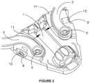
Figure 2 , we are shown that a pair ofgrub screws 13 and 13' are adapted to be screwed into each respective threaded hole. When a tool such as a screw driver, or Allen key or the like is used, the grub screws may be turned. As each is turned, eventually the innermost end of the screw impinges upon the outermost side of its respective arm. This forces the arm to yield under the force applied by the screw. This causes the respective arm to move in the direction indicated by the arrows. - Turning to
Figure 3 , we are shown thetop plate 15 ready to be attached to thebottom plate 1. Thetop plate 15 includes a pair of downwardly extendingtabs 17 and 17' respectively. The size and shape of each of the tabs is selected so that when the top and bottom plates are connected, the tabs fit flush inside therespective slots 9 and 9'. Eachtab 17 and 17' includes asmall aperture 19 and 19'. These apertures are adapted to be concentric with the hole and grub screws when the body portion is assembled. The aperture is sized so that a tool may pass through the aperture and engage the head of the grub screw, thereby enabling it to be turned in order to adjust the position of each arm. It is also sized so that the aperture is too small for the grub screw to be able to withdraw back through it if the screw is unwound within the threaded hole. Eachrespective tab 17 and 17' thereby acts as an abutment that prevents it's respective grub screw from falling out of the body portion. - In
Figure 4 , the body portion is assembled and illustrates how thetab 17 in thetop plate 15 fits flush with the slot in thebottom plate 1. -
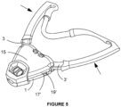
Figure 5 shows the body portion comprisingtop plate 15 andbottom plate 1 assembled with other intraoral components of the mandibular advancement device. Adjustment of each respective grub screw by inserting a tool throughaperture 19 and 19' causes thearms 3 and 3' to move closer together as shown by the arrows. In this embodiment, due to the natural resilience of the material from which the arms are fabricated, unscrewing the grub screw causes its respective arm to return to its normal rest position. -
Figure 6 shows an optional feature on thetop plate 15. In this embodiment of the invention, a pair ofwindows 21 and 21'. Each window includesmeasurement graduations 23 and 23'. These offer the user a visual aid in determining the position of eacharm 3 and 3'. The user can then determine the best arm position for that particular wearer of the device. This will particularly assist a user to setup subsequent devices for a particular wearer and manually set the arms into the initial best position for that particular person. -
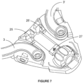
Figure 7 shows another preferred embodiment of the invention. In this view, the body portion is fitted withelectronic sensors 25 and 25 '. These sensors electronically sense the position of eacharm 3 and 3'. The position data is then optionally transmitted via wireless means 27 to a portable computing device such as a smartphone. The smartphone has an app installed that links the position data to the user's account and logs the selected position of each arm that the wearer of the device finds to be the most comfortable. This data can then be used in the future when setting up ancillary or replacement devices for that particular wearer. -
Figures 8 (a) and (b) show a preferred embodiment of the invention where a pair ofnatural leaf springs 29 and 29' are prefabricated into thebottom plate 1. Each of thearms 3 and 3' are fabricated separately to thebottom plate 1, and each arm includes acircular hole 33 and 33' respectively at its anterior end which is designed to be placed upon astake 31 and 31' respectively. Each stake also has a matching circular profile. Each arm is then able to rotate about its respective stake, however each arm is biased into its maximum spread position by the force applied upon it by a respective leaf spring. -
Figures 9 (a) and (b) show another preferred embodiment of the present invention. In this embodiment, each of thearms 3 and 3' are fabricated separately to thebottom plate 1, however each of theholes 33 and 33' are no longer circular in profile. Each of thestakes 31 and 31' that a respective arm is placeable upon has a matching non-circular profile. The shape of the stake and the hole on the arm prevent the arm from rotating about the stake, and this holds each arm in its maximum spread position. Any force applied to a respective arm imposed by the grub screw will cause the arm to move towards its opposite arm. When the force is removed, the arm will move back to its maximum spread position under the influence of its own resilience. -
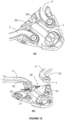
Figures 10 (a) and (b) show another preferred embodiment of the present invention. In this embodiment, each of thearms 3 and 3' are fabricated separately to thebottom plate 1, and each is able to be placed upon aprefabricated stake 31 and 31', and both the stakes and the holes in the arms have a circular profile, so that each arm is able to rotate around its respective stake, however a pair ofsprings 35 and 35' are included in the assembly, and each spring applies a biasing force to a respective arm that holds the arm in its maximum spread position until acted upon by a respective grub screw. - So, from the aforementioned preferred embodiments, it can be seen that the present invention provides an easy way for a user to setup the intraoral portion of a mandibular advancement device so that it may have improved fit, comfort upon the wearer, and may also provide more efficient function.
- While the above description includes the preferred embodiments of the invention, it is to be understood that many variations, alterations, modifications and/or additions may be introduced into the constructions and arrangements of parts previously described without departing from the essential features of the invention. For example, the adjustment means in the preferred embodiment uses a threaded hole and associated grub screw, however other means of adjusting the position of the arm with respect to the other arm are possible, such as elector-mechanical means, or magnetic means. These should be considered within the scope of the present invention. Such means offer the ability to avoid the need for apertures in both the top and bottom plates, thereby making their respective surfaces continuous and thereby easier to clean and to sterilise between uses.
- It will be also understood that where the word "comprise", and variations such as "comprises" and "comprising", are used in this specification, unless the context requires otherwise such use is intended to imply the inclusion of a stated feature or features but is not to be taken as excluding the presence of other feature or features.
- The reference to any prior art in this specification is not, and should not be taken as, an acknowledgment or any form of suggestion that such prior art forms part of the common general knowledge.
Claims (15)
- A mandibular advancement device including:an intraoral portion including a body portion, the body portion including lower (1) and upper (15) plates, the lower plate (1) being adapted to accommodate a pair of opposed arms (3, 3'), that extend rearwardly and outwardly from the lower plate (1) into an oral cavity when the device is worn, each arm including a posterior intraoral maxillary abutment surface, andan extraoral portion,characterised in thatthe mandibular advancement device includes an adjustment means provided on each side of the lower plate (1), the adjustment means adapted to act upon a respective arm to move the respective arm towards its opposing arm, so that the respective arm's posterior intraoral maxillary abutment surface is moved to a new position.
- The mandibular advancement device as defined in claim 1 wherein the adjustment means comprises screws (13, 13'), and wherein each side of the lower plate (1) of the device includes a threaded hole (7, 7'), adjacent a respective arm, so that the threaded hole (7, 7') extends from the respective arm towards an edge of the lower plate (1), and wherein each hole (7, 7') is adapted to receive a screw of the adjustment means that is able to be screwed into the threaded hole (7, 7'), and when the screw (13, 13') has been sufficiently screwed into said threaded hole (7, 7'), an inner end of the screw (13, 13') contacts its respective arm whereupon further turning of the screw (13, 13') forces the respective arm to move towards its opposing arm so that the respective arm's posterior intraoral maxillary abutment surface is moved to a new position.
- The mandibular advancement device as defined in claim 2 wherein:each threaded hole (7, 7') in the lower plate (1) of the device is recessed back from the edge and an opening of the threaded hole (7, 7') is respectively located within a vertical slot (9, 9'); and optionallythe upper plate (15) of the device is adapted to overlay the lower plate (1) and join together with the lower plate (1) to form the body portion and encapsulate a portion of each of the arms within the body portion.
- The mandibular advancement device as defined in claim 3 wherein the upper plate (15) of the device includes side tabs (17, 17') that extend substantially vertically down and are aligned with and adapted to be inserted into, and conform with the shape of, the vertical slot (9, 9'), thereby overlaying the opening of the threaded hole (7, 7') and screw (13, 13') and forming the body portion with a substantially smooth outer surface.
- The mandibular advancement device as defined in claim 4 wherein each side tab (17, 17') of the device includes an aperture that is positioned so that it aligns with, and is concentric with, the threaded hole (7, 7') and the screw (13, 13').
- The mandibular advancement device as defined in claim 5 wherein each aperture of the device is sized so that an adjustment tool is insertable, and is thereby able to engage with and act upon the screw (13, 13'), but is too small to enable the screw (13, 13') to be withdrawn through the aperture, thereby making the side tab (17, 17') act as an abutment that prevents the screw (13, 13') from falling out of the body portion.
- The mandibular advancement device as defined in claim 1 wherein each arm (3, 3') of the device is integrally formed in either the upper or lower plate and fabricated out of a suitable elastomeric material.
- The mandibular advancement device as defined in claim 7 wherein each arm of the device is naturally biased with respect to the other with a maximum spread that the arms naturally rest at when not acted on by the adjustment means.
- The mandibular advancement device as defined in claim 1 wherein:each arm of the device is fabricated separately to either the upper or lower plate (1), and either the upper or lower plate (1) includes a respective post portion for each arm that is profiled to resist rotation around the post portion, and an anterior end of each arm includes a hole (33, 33') that has a complimentary shape with, and is adapted to receive, the post portion within said hole (33, 33'), the post portion being received within said hole (33, 33') being a natural rest position for each arm when the arm is not acted upon by the adjustment means; oreach arm of the device is fabricated separately to either the upper plate (15) or the lower plate (1), and either the upper plate (15) or lower plate (1) includes a respective post portion with a circular profile, and an anterior end of each arm includes a hole that is adapted to receive the post portion and allow the arm to freely rotate about its respective post portion, and the body portion includes separate biasing means that act upon each respective arm and hold the arms at their maximum spread position when each arm is not acted upon by the adjustment means.
- The mandibular advancement device as defined in claim 9 wherein the biasing means of the device is at least one of a coil spring, a leaf spring, or an elastomeric tab that is included in either the upper plate (15) or the lower plate (1), the elastomeric tab being adapted to impinge against a respective arm.
- The mandibular advancement device as defined in any previous claim wherein either the upper or lower plate (1) of the device includes an aperture, or window, that is associated with measurement increment indicators, and said measurement increment indicators indicate a current position of each arm as the arm is forced to a new position by the adjustment means.
- The mandibular advancement device as defined in claim 11 wherein the body portion of the device includes electronic sensor means that are adapted to sense the current position of each arm and feed that position data to wireless transmission means such as a Bluetooth transmitter; and optionally
the position data are transmitted by the wireless transmission means and are processed by an app on a portable computing device. - A method of adjusting the mandibular advancement device as defined in claim 1, the method including:a. selecting an appropriate mandibular advancement device from a selection of small, medium and large size mandibular advancement devices;b. inserting the device into a wearer's mouth;c. determining a fit and comfort of the device by bracing each intraoral maxillary abutment surface against an extramaxillary anterior maxillary abutment surface;d. receiving feedback from the wearer on the fit and comfort; ande. using an appropriate tool to engage the adjustment means to force each respective arm to change position and thereby causing each posterior intraoral maxillary abutment surface to change position to provide a custom fit of the device for the wearer.
- The method as defined in claim 13 wherein step e. comprises using an appropriate tool to insert into the threaded hole and thereby engaging a screw of the adjustment means and turning it to force each respective arm to change position and thereby causing each posterior intraoral maxillary abutment surface to change position to provide a custom fit of the device for the wearer.
- The method as defined in claim 13 or claim 14 wherein either the upper or lower plate (1) of the device further includes an aperture, or window, that is associated with measurement increment indicators, and said measurement increment indicators indicate a current position of each arm as the arm is forced to a new position under the influence of the screw, said method further including using the aperture, or window, and its associated measurement increment indicators to take note of the most comfortable setting for the particular wearer, and optionally
wherein the body portion of the device further includes electronic sensor means that are adapted to sense the current position of each arm and feed that position data to wireless transmission means such as a Bluetooth transmitter, and wherein the position data are transmittable by the wireless transmission means and are processable by an app on a portable computing device, said method further including using the sensor means and wireless transmission means to transmit the position data of each arm in an app on a portable computing device to associate the optimal position of each arm to the wearer.
Applications Claiming Priority (2)
| Application Number | Priority Date | Filing Date | Title |
|---|---|---|---|
| AU2019903104A AU2019903104A0 (en) | 2019-08-26 | Adjustment Means | |
| PCT/AU2020/000087 WO2021035277A1 (en) | 2019-08-26 | 2020-08-26 | Adjustment means for a mandibular advancement device |
Publications (4)
| Publication Number | Publication Date |
|---|---|
| EP4021357A1 EP4021357A1 (en) | 2022-07-06 |
| EP4021357A4 EP4021357A4 (en) | 2023-08-16 |
| EP4021357C0 EP4021357C0 (en) | 2024-09-11 |
| EP4021357B1 true EP4021357B1 (en) | 2024-09-11 |
Family
ID=74683765
Family Applications (1)
| Application Number | Title | Priority Date | Filing Date |
|---|---|---|---|
| EP20857115.8A Active EP4021357B1 (en) | 2019-08-26 | 2020-08-26 | Adjustment means for a mandibular advancement device |
Country Status (5)
| Country | Link |
|---|---|
| US (1) | US20220313394A1 (en) |
| EP (1) | EP4021357B1 (en) |
| CN (1) | CN114340570A (en) |
| AU (1) | AU2020338476B2 (en) |
| WO (1) | WO2021035277A1 (en) |
Families Citing this family (1)
| Publication number | Priority date | Publication date | Assignee | Title |
|---|---|---|---|---|
| CN120114210B (en) * | 2025-04-14 | 2026-01-27 | 华中科技大学同济医学院附属协和医院 | Adjustable OSA treatment device convenient to wear |
Family Cites Families (18)
| Publication number | Priority date | Publication date | Assignee | Title |
|---|---|---|---|---|
| US4433956A (en) * | 1981-07-27 | 1984-02-28 | Witzig John W | Orthopedic corrector and method of correction of Class II malocclusion |
| US5078600A (en) * | 1990-06-25 | 1992-01-07 | Austin David G | Multifunction mandibular movement measuring device |
| US6152730A (en) * | 1998-07-29 | 2000-11-28 | Wildman; Alexander J. | Bite registration tracing appliance with movable lower wing |
| CA2635438C (en) * | 2005-01-10 | 2014-10-21 | Guoping Yan | Method and device for mandibular advancement |
| WO2010141868A2 (en) * | 2009-06-05 | 2010-12-09 | Uti Limited Partnership | Apparatuses and methods for mandibular protrusion |
| ES2365003B2 (en) * | 2009-10-22 | 2012-02-13 | Laboratorio Ortoplus, S.L. | INTRA-ORAL DEVICE FOR ADJUSTABLE MANDIBULAR ADVANCE, APPLICABLE TO AVOID THE SOUND AND THE APNEA OF THE DREAM. |
| CN101822606B (en) * | 2010-05-19 | 2012-11-14 | 四川大学 | Integral-type initiative oral cavity mouth gag |
| DE202010017014U1 (en) * | 2010-12-23 | 2011-02-24 | Köklü, Saduman Oguzhan, Dr. | Orthodontic apparatus |
| US20140261450A1 (en) * | 2013-03-15 | 2014-09-18 | Michael Brady Morehead | Intraoral mandibular advancing positive pressure apparatus |
| US20150272773A1 (en) * | 2014-03-31 | 2015-10-01 | MAP Laboratory LLC | Intraoral apparatus for managing snoring and obstructive sleep apnea |
| US11246743B2 (en) * | 2014-06-04 | 2022-02-15 | Archis Health Investments | System and method for sensor driven intelligent oral appliance |
| CN206880919U (en) * | 2016-03-30 | 2018-01-16 | 奥温特斯医疗有限公司 | Equipment for providing Respiration assistance |
| CN206508393U (en) * | 2016-11-23 | 2017-09-22 | 刘帆 | A kind of simple electric shock device for preventing snoring |
| EP3694400A4 (en) | 2017-10-13 | 2021-07-28 | Bioanalytics Holdings Pty Ltd | SLEEP MONITORING ADVANCEMENTS |
| US12213907B2 (en) * | 2017-11-13 | 2025-02-04 | Achaemenid, Llc | Provisional oral sleep appliance |
| CN208481836U (en) * | 2017-12-19 | 2019-02-12 | 易娟 | ICU patient's jaw pad |
| US11045348B2 (en) * | 2018-05-08 | 2021-06-29 | Archis Health Investments LLC | Apparatus for mandibular advancement of an oral appliance |
| CN109602534A (en) * | 2019-01-15 | 2019-04-12 | 兴康明科技(深圳)有限公司 | A mandibular advancement snoring device with intelligent automatic adjustment |
-
2020
- 2020-08-26 AU AU2020338476A patent/AU2020338476B2/en active Active
- 2020-08-26 US US17/753,287 patent/US20220313394A1/en active Pending
- 2020-08-26 WO PCT/AU2020/000087 patent/WO2021035277A1/en not_active Ceased
- 2020-08-26 EP EP20857115.8A patent/EP4021357B1/en active Active
- 2020-08-26 CN CN202080059316.1A patent/CN114340570A/en active Pending
Also Published As
| Publication number | Publication date |
|---|---|
| CN114340570A (en) | 2022-04-12 |
| EP4021357C0 (en) | 2024-09-11 |
| WO2021035277A1 (en) | 2021-03-04 |
| EP4021357A1 (en) | 2022-07-06 |
| AU2020338476B2 (en) | 2026-01-08 |
| AU2020338476A1 (en) | 2022-03-10 |
| US20220313394A1 (en) | 2022-10-06 |
| EP4021357A4 (en) | 2023-08-16 |
Similar Documents
| Publication | Publication Date | Title |
|---|---|---|
| AU2021250941B2 (en) | A mandibular advancement device | |
| US7748386B2 (en) | Oral appliance for treating a breathing condition | |
| EP3363413B1 (en) | Lower jaw advancing apparatus | |
| ES2321085T3 (en) | ADJUSTABLE HYDROCEPHAL VALVE. | |
| US20110316705A1 (en) | Devices, systems, and methods for monitoring sleep position | |
| EP2303197B1 (en) | Orthopedic technical device | |
| US20100307511A1 (en) | Mandibular Advancement Appliance | |
| AU2020338476B2 (en) | Adjustment means for a mandibular advancement device | |
| WO2005027716A3 (en) | Program for regulating health conditions | |
| US20200289241A1 (en) | Sensor and system for monitoring the wearing duration of orthodontic elastics | |
| WO2015017790A1 (en) | In-ear proprioceptive for relieving temporomandibular joint-related symptoms | |
| WO2015017771A2 (en) | In-ear device with at least one sensor | |
| KR102192633B1 (en) | Apparatus For Correcting Forward Head Posture | |
| DE102014201694A1 (en) | Device for detecting an unhealthy situation of a person lying down, in particular an anti-snoring device | |
| US6553623B2 (en) | Automatic pivot door opener | |
| CN108937826B (en) | A kind of intelligent children's mouth mouth guard | |
| WO2015017785A1 (en) | Methods for reducing one or more symptoms of temporomandibular joint disorder | |
| EP1659826A2 (en) | Hearing-aid and corresponding method for inserting the hearing aid | |
| EP4346692A1 (en) | Dental prosthetic device and method of forming same | |
| JP3093992B2 (en) | Posture correction tool | |
| EP4021359B1 (en) | Adjustment means for a mandibular advancement device | |
| KR101374383B1 (en) | Dental punching apparatus | |
| KR20170091840A (en) | Automatic belt apparatus | |
| DE102025140424A1 (en) | Devices and methods for reducing bruxism, craniomandibular dysfunction, sleep apnea and other parafunctional movements through biofeedback | |
| JP2005290957A (en) | Door, biting preventive device for rotary door |
Legal Events
| Date | Code | Title | Description |
|---|---|---|---|
| STAA | Information on the status of an ep patent application or granted ep patent |
Free format text: STATUS: THE INTERNATIONAL PUBLICATION HAS BEEN MADE |
|
| PUAI | Public reference made under article 153(3) epc to a published international application that has entered the european phase |
Free format text: ORIGINAL CODE: 0009012 |
|
| STAA | Information on the status of an ep patent application or granted ep patent |
Free format text: STATUS: REQUEST FOR EXAMINATION WAS MADE |
|
| 17P | Request for examination filed |
Effective date: 20220325 |
|
| AK | Designated contracting states |
Kind code of ref document: A1 Designated state(s): AL AT BE BG CH CY CZ DE DK EE ES FI FR GB GR HR HU IE IS IT LI LT LU LV MC MK MT NL NO PL PT RO RS SE SI SK SM TR |
|
| RIN1 | Information on inventor provided before grant (corrected) |
Inventor name: SASSE, ANTHONY Inventor name: YAN, GUOPING Inventor name: MORGAN, OWEN |
|
| DAV | Request for validation of the european patent (deleted) | ||
| DAX | Request for extension of the european patent (deleted) | ||
| A4 | Supplementary search report drawn up and despatched |
Effective date: 20230719 |
|
| RIC1 | Information provided on ipc code assigned before grant |
Ipc: A61F 5/56 20060101AFI20230713BHEP |
|
| GRAP | Despatch of communication of intention to grant a patent |
Free format text: ORIGINAL CODE: EPIDOSNIGR1 |
|
| STAA | Information on the status of an ep patent application or granted ep patent |
Free format text: STATUS: GRANT OF PATENT IS INTENDED |
|
| INTG | Intention to grant announced |
Effective date: 20240426 |
|
| GRAS | Grant fee paid |
Free format text: ORIGINAL CODE: EPIDOSNIGR3 |
|
| GRAA | (expected) grant |
Free format text: ORIGINAL CODE: 0009210 |
|
| STAA | Information on the status of an ep patent application or granted ep patent |
Free format text: STATUS: THE PATENT HAS BEEN GRANTED |
|
| AK | Designated contracting states |
Kind code of ref document: B1 Designated state(s): AL AT BE BG CH CY CZ DE DK EE ES FI FR GB GR HR HU IE IS IT LI LT LU LV MC MK MT NL NO PL PT RO RS SE SI SK SM TR |
|
| REG | Reference to a national code |
Ref country code: GB Ref legal event code: FG4D |
|
| REG | Reference to a national code |
Ref country code: CH Ref legal event code: EP |
|
| REG | Reference to a national code |
Ref country code: DE Ref legal event code: R096 Ref document number: 602020037715 Country of ref document: DE |
|
| REG | Reference to a national code |
Ref country code: IE Ref legal event code: FG4D |
|
| U01 | Request for unitary effect filed |
Effective date: 20241009 |
|
| U07 | Unitary effect registered |
Designated state(s): AT BE BG DE DK EE FI FR IT LT LU LV MT NL PT RO SE SI Effective date: 20241029 |
|
| PG25 | Lapsed in a contracting state [announced via postgrant information from national office to epo] |
Ref country code: GR Free format text: LAPSE BECAUSE OF FAILURE TO SUBMIT A TRANSLATION OF THE DESCRIPTION OR TO PAY THE FEE WITHIN THE PRESCRIBED TIME-LIMIT Effective date: 20241212 |
|
| PG25 | Lapsed in a contracting state [announced via postgrant information from national office to epo] |
Ref country code: HR Free format text: LAPSE BECAUSE OF FAILURE TO SUBMIT A TRANSLATION OF THE DESCRIPTION OR TO PAY THE FEE WITHIN THE PRESCRIBED TIME-LIMIT Effective date: 20240911 |
|
| PG25 | Lapsed in a contracting state [announced via postgrant information from national office to epo] |
Ref country code: RS Free format text: LAPSE BECAUSE OF FAILURE TO SUBMIT A TRANSLATION OF THE DESCRIPTION OR TO PAY THE FEE WITHIN THE PRESCRIBED TIME-LIMIT Effective date: 20241211 Ref country code: ES Free format text: LAPSE BECAUSE OF FAILURE TO SUBMIT A TRANSLATION OF THE DESCRIPTION OR TO PAY THE FEE WITHIN THE PRESCRIBED TIME-LIMIT Effective date: 20240911 |
|
| PG25 | Lapsed in a contracting state [announced via postgrant information from national office to epo] |
Ref country code: RS Free format text: LAPSE BECAUSE OF FAILURE TO SUBMIT A TRANSLATION OF THE DESCRIPTION OR TO PAY THE FEE WITHIN THE PRESCRIBED TIME-LIMIT Effective date: 20241211 Ref country code: HR Free format text: LAPSE BECAUSE OF FAILURE TO SUBMIT A TRANSLATION OF THE DESCRIPTION OR TO PAY THE FEE WITHIN THE PRESCRIBED TIME-LIMIT Effective date: 20240911 Ref country code: GR Free format text: LAPSE BECAUSE OF FAILURE TO SUBMIT A TRANSLATION OF THE DESCRIPTION OR TO PAY THE FEE WITHIN THE PRESCRIBED TIME-LIMIT Effective date: 20241212 Ref country code: ES Free format text: LAPSE BECAUSE OF FAILURE TO SUBMIT A TRANSLATION OF THE DESCRIPTION OR TO PAY THE FEE WITHIN THE PRESCRIBED TIME-LIMIT Effective date: 20240911 |
|
| PG25 | Lapsed in a contracting state [announced via postgrant information from national office to epo] |
Ref country code: IS Free format text: LAPSE BECAUSE OF FAILURE TO SUBMIT A TRANSLATION OF THE DESCRIPTION OR TO PAY THE FEE WITHIN THE PRESCRIBED TIME-LIMIT Effective date: 20250111 |
|
| PG25 | Lapsed in a contracting state [announced via postgrant information from national office to epo] |
Ref country code: SM Free format text: LAPSE BECAUSE OF FAILURE TO SUBMIT A TRANSLATION OF THE DESCRIPTION OR TO PAY THE FEE WITHIN THE PRESCRIBED TIME-LIMIT Effective date: 20240911 |
|
| PG25 | Lapsed in a contracting state [announced via postgrant information from national office to epo] |
Ref country code: PL Free format text: LAPSE BECAUSE OF FAILURE TO SUBMIT A TRANSLATION OF THE DESCRIPTION OR TO PAY THE FEE WITHIN THE PRESCRIBED TIME-LIMIT Effective date: 20240911 Ref country code: CZ Free format text: LAPSE BECAUSE OF FAILURE TO SUBMIT A TRANSLATION OF THE DESCRIPTION OR TO PAY THE FEE WITHIN THE PRESCRIBED TIME-LIMIT Effective date: 20240911 |
|
| PG25 | Lapsed in a contracting state [announced via postgrant information from national office to epo] |
Ref country code: SK Free format text: LAPSE BECAUSE OF FAILURE TO SUBMIT A TRANSLATION OF THE DESCRIPTION OR TO PAY THE FEE WITHIN THE PRESCRIBED TIME-LIMIT Effective date: 20240911 |
|
| U1N | Appointed representative for the unitary patent procedure changed after the registration of the unitary effect |
Representative=s name: METIDA; LT |
|
| PLBE | No opposition filed within time limit |
Free format text: ORIGINAL CODE: 0009261 |
|
| STAA | Information on the status of an ep patent application or granted ep patent |
Free format text: STATUS: NO OPPOSITION FILED WITHIN TIME LIMIT |
|
| 26N | No opposition filed |
Effective date: 20250612 |
|
| U20 | Renewal fee for the european patent with unitary effect paid |
Year of fee payment: 6 Effective date: 20250822 |
|
| PGFP | Annual fee paid to national office [announced via postgrant information from national office to epo] |
Ref country code: NO Payment date: 20250828 Year of fee payment: 6 |
|
| PGFP | Annual fee paid to national office [announced via postgrant information from national office to epo] |
Ref country code: GB Payment date: 20250822 Year of fee payment: 6 |
|
| REG | Reference to a national code |
Ref country code: CH Ref legal event code: H13 Free format text: ST27 STATUS EVENT CODE: U-0-0-H10-H13 (AS PROVIDED BY THE NATIONAL OFFICE) Effective date: 20260324 |
|
| PG25 | Lapsed in a contracting state [announced via postgrant information from national office to epo] |
Ref country code: MC Free format text: LAPSE BECAUSE OF FAILURE TO SUBMIT A TRANSLATION OF THE DESCRIPTION OR TO PAY THE FEE WITHIN THE PRESCRIBED TIME-LIMIT Effective date: 20240911 |
|
| PG25 | Lapsed in a contracting state [announced via postgrant information from national office to epo] |
Ref country code: CH Free format text: LAPSE BECAUSE OF NON-PAYMENT OF DUE FEES Effective date: 20250831 |