EP4020794A1 - Motor control device - Google Patents
Motor control device Download PDFInfo
- Publication number
- EP4020794A1 EP4020794A1 EP21216637.5A EP21216637A EP4020794A1 EP 4020794 A1 EP4020794 A1 EP 4020794A1 EP 21216637 A EP21216637 A EP 21216637A EP 4020794 A1 EP4020794 A1 EP 4020794A1
- Authority
- EP
- European Patent Office
- Prior art keywords
- offset
- motor
- drive voltage
- correction value
- temperature
- Prior art date
- Legal status (The legal status is an assumption and is not a legal conclusion. Google has not performed a legal analysis and makes no representation as to the accuracy of the status listed.)
- Granted
Links
Images



Classifications
-
- H—ELECTRICITY
- H02—GENERATION; CONVERSION OR DISTRIBUTION OF ELECTRIC POWER
- H02P—CONTROL OR REGULATION OF ELECTRIC MOTORS, ELECTRIC GENERATORS OR DYNAMO-ELECTRIC CONVERTERS; CONTROLLING TRANSFORMERS, REACTORS OR CHOKE COILS
- H02P29/00—Arrangements for regulating or controlling electric motors, appropriate for both AC and DC motors
- H02P29/60—Controlling or determining the temperature of the motor or of the drive
- H02P29/64—Controlling or determining the temperature of the winding
-
- H—ELECTRICITY
- H02—GENERATION; CONVERSION OR DISTRIBUTION OF ELECTRIC POWER
- H02P—CONTROL OR REGULATION OF ELECTRIC MOTORS, ELECTRIC GENERATORS OR DYNAMO-ELECTRIC CONVERTERS; CONTROLLING TRANSFORMERS, REACTORS OR CHOKE COILS
- H02P25/00—Arrangements or methods for the control of AC motors characterised by the kind of AC motor or by structural details
- H02P25/02—Arrangements or methods for the control of AC motors characterised by the kind of AC motor or by structural details characterised by the kind of motor
- H02P25/032—Reciprocating, oscillating or vibrating motors
- H02P25/034—Voice coil motors
-
- H—ELECTRICITY
- H02—GENERATION; CONVERSION OR DISTRIBUTION OF ELECTRIC POWER
- H02P—CONTROL OR REGULATION OF ELECTRIC MOTORS, ELECTRIC GENERATORS OR DYNAMO-ELECTRIC CONVERTERS; CONTROLLING TRANSFORMERS, REACTORS OR CHOKE COILS
- H02P21/00—Arrangements or methods for the control of electric machines by vector control, e.g. by control of field orientation
- H02P21/14—Estimation or adaptation of machine parameters, e.g. flux, current or voltage
-
- H—ELECTRICITY
- H02—GENERATION; CONVERSION OR DISTRIBUTION OF ELECTRIC POWER
- H02P—CONTROL OR REGULATION OF ELECTRIC MOTORS, ELECTRIC GENERATORS OR DYNAMO-ELECTRIC CONVERTERS; CONTROLLING TRANSFORMERS, REACTORS OR CHOKE COILS
- H02P29/00—Arrangements for regulating or controlling electric motors, appropriate for both AC and DC motors
- H02P29/02—Providing protection against overload without automatic interruption of supply
- H02P29/032—Preventing damage to the motor, e.g. setting individual current limits for different drive conditions
Definitions
- the present invention relates to a motor control device that controls driving of a motor, particularly of a voice coil motor.
- a tactile feedback technology in which an operation site is vibrated using a voice coil motor (VCM) or the like has been known (see, for example, JP 2012-176640 A ).
- VCM voice coil motor
- the voice coil motor used as one of vibration sources generates vibration by applying a sinusoidal drive voltage with reversed phase across a coil.
- a bias occurs in the drive voltage applied across the coil such that the center of amplitude does not become 0 V and a direct current (DC) offset occurs
- DC current flows through the coil due to the DC offset, and a temperature rises.
- the temperature rise becomes excessive, a coating film of the coil melts, leading to smoking and burning. Therefore, it is necessary to detect a DC offset exceeding a predetermined threshold and perform a control to stop the application of the drive voltage.
- the threshold serving as a reference for determining whether or not the application of the drive voltage is to be stopped is excessively low, slight noise during a normal operation may be detected, and the operation of the voice coil motor may be frequently stopped.
- the reference threshold is excessively high, a state in which a relatively high DC offset has occurred for a long time until the threshold is reached continues, and the temperature of the voice coil motor rises.
- the voice coil motor has temperature dependency, and in order to obtain a certain amount of vibration, it is necessary to increase the drive voltage with the temperature rise. For this reason, even when smoking and burning of the coil can be avoided, a state in which the high temperature continues for a long time is not preferable.
- An object of the present invention is to provide a motor control device capable of securing an appropriate vibration amount while preventing burning of a coil due to a DC offset of a drive voltage.
- the invention relates to a motor control device according to the appended claims. Embodiments are disclosed in the dependent claims.
- a motor control device generates vibration in a motor by applying a drive voltage with reversed phase across a motor coil
- the motor control device including: drive voltage generation means that generates the drive voltage; DC offset detection means that detects a DC offset of the drive voltage; stop means that stops the application of the drive voltage to the motor coil when the detected DC offset exceeds an operation stop threshold; temperature correction value setting means that sets a temperature correction value corresponding to the DC offset when the detected DC offset is lower than the operation stop threshold; ambient temperature detection means that detects an ambient temperature; and vibration level control means that varies the drive voltage and controls an amplitude level based on the detected ambient temperature and the set temperature correction value.
- the motor coil can be prevented from being damaged by stopping the operation when the DC offset becomes excessive.
- the DC offset does not become excessive, by varying the drive voltage when the temperature rises with the occurrence of the DC offset and/or with the rise of the ambient temperature, it is possible to secure an appropriate vibration amount regardless of the temperature rise.
- the drive voltage has a sinusoidal waveform with reversed phase.
- the temperature correction value setting means sets the temperature correction value proportional to the DC offset. This makes it possible to set the temperature correction value corresponding to the temperature rise accompanying an increase in the DC offset.
- the temperature correction value is a value assuming an amount of temperature rise of the motor coil due to the occurrence of the DC offset, wherein the vibration level control means increases the drive voltage applied to the motor coil as a total temperature obtained by adding the temperature correction value to the ambient temperature. This makes it possible to obtain a certain vibration level regardless of the DC offset or the ambient temperature.
- the ambient temperature detection means is installed on the same substrate as that of the motor to detect the ambient temperature. According to an embodiment the ambient temperature detection means is installed in the same housing as that of the motor to detect the ambient temperature. This makes it possible to detect the ambient temperature that raises the temperature of the motor.
- the motor is a voice coil motor. This makes it possible to ensure a constant amount of vibration of the voice coil motor while preventing the coil from being damaged due to a temperature rise.
- Fig. 1 is a diagram illustrating a configuration of the motor control device according to the embodiment.
- a motor control device 100 of the present embodiment includes a waveform generation unit 110, an amplifier 120, a direct current (DC) offset detection unit 130, a thermistor 140, and a vibration control unit 150.
- the motor control device 100 applies a drive voltage with reversed phase across a motor coil 210 of a voice coil motor (VCM) 200 to generate vibration in the VCM 200.
- VCM voice coil motor
- the VCM 200 to be controlled is provided in, for example, an operation device mounted on a vehicle, and is used to implement tactile feedback that generates vibration according to an operation of a user.
- the waveform generation unit 110 generates two types of drive signals having a sinusoidal waveform with reversed phase.
- the amplifier 120 amplifies the two types of drive signals having a sinusoidal waveform to generate drive voltages, and applies each drive voltage across the motor coil 210 of the VCM 200.
- the DC offset detection unit 130 detects the DC offset included in the drive voltage applied across the motor coil 210. Theoretically, in a case where the drive voltage having a sinusoidal waveform with reversed phase is applied across the motor coil 210, the center voltage is 0 V, and a DC offset that is a deviation from the center voltage does not occur (0 V). However, the DC offset may occur due to a deviation of an element constant of a component, an abnormality, or the like.
- the thermistor 140 is a temperature detection element installed on the same substrate (or in the same housing) as that of the VCM 200, and detects the ambient temperature of the VCM 200.
- the VCM 200 and the thermistor 140 may be mounted on a common substrate, or the VCM 200 and the thermistor 140 may be mounted in a common housing.
- the vibration control unit 150 controls a vibration level of the VCM 200 based on the DC offset detected by the DC offset detection unit 130 and the ambient temperature detected using the thermistor 140. Therefore, the vibration control unit 150 includes a stop control unit 152, a temperature correction value setting unit 154, and a vibration level control unit 156.
- the stop control unit 152 stops the application of the drive voltage to the motor coil 210 when the DC offset detected by the DC offset detection unit 130 exceeds an operation stop threshold (for example, 2 V).
- an operation stop threshold for example, 2 V.
- an instruction may be issued to the waveform generation unit 110 to stop the operation of generating the drive signal.
- an instruction may be issued to the amplifier 120 to stop an operation of amplifying the drive signal.
- the temperature correction value setting unit 154 sets a temperature correction value corresponding to the DC offset. A specific example of the setting will be described later.
- the vibration level control unit 156 transmits an instruction to the waveform generation unit 110 to vary a sinusoidal amplitude based on the ambient temperature detected using the thermistor 140 and the temperature correction value set by the temperature correction value setting unit 154, thereby varying the drive voltage applied from the amplifier 120 to the motor coil 210 to control the amplitude level of the VCM 200.
- the waveform generation unit 110 and the amplifier 120 described above correspond to drive voltage generation means
- the DC offset detection unit 130 corresponds to DC offset detection means
- the stop control unit 152 corresponds to stop means
- the temperature correction value setting unit 154 corresponds to temperature correction value setting means
- the thermistor 140 corresponds to ambient temperature detection means
- the vibration level control unit 156 corresponds to vibration level control means.
- the motor control device 100 has the above-described configuration. Next, an operation thereof will be described.
- Fig. 2 is a flowchart illustrating an operation procedure of the motor control device 100 that controls a vibration state of the VCM 200 according to the DC offset or the ambient temperature according to an embodiment.
- the stop control unit 152 and the temperature correction value setting unit 154 acquire the DC offset detected by the DC offset detection unit 130 based on the drive voltage having a sinusoidal waveform applied from the amplifier 120 to the motor coil 210 (Step 100).
- the stop control unit 152 determines whether or not the DC offset exceeds 2 V as the operation stop threshold (Step 102). In a case where the voltage exceeds 2 V, the processing proceeds along "YES" branch, and the stop control unit 152 stops the application of the drive voltage to the motor coil 210 (Step 104).
- the processing proceeds along "NO" branch from Step 102.
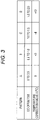
- the temperature correction value setting unit 154 sets the temperature correction value X corresponding to the DC offset based on a temperature correction value table (Step 106).
- Fig. 3 is a diagram illustrating an example of the temperature correction value table.
- a range in which the DC offset is equal to or less than the operation stop threshold is divided into the following four patterns A, B, C, and D.
- Pattern A The DC offset corresponds to a range of 0 V or more and 0.5 V or less. In a case where the DC offset falls within this range, the temperature correction value X is set to 0°C.
- Pattern B The DC offset corresponds to a range of more than 0.5 V and 1.0 V or less. In a case where the DC offset falls within this range, the temperature correction value X is set to +3°C.
- Pattern C The DC offset corresponds to a range of more than 1.0 V and 1.5 V or less. In a case where the DC offset falls within this range, the temperature correction value X is set to +8°C.
- Pattern D The DC offset corresponds to a range of more than 1.5 V and 2.0 V or less. In a case where the DC offset falls within this range, the temperature correction value X is set to +13°C.
- the vibration level control unit 156 acquires an ambient temperature Y detected by the thermistor 140 (Step 108).
- the vibration level control unit 156 estimates a temperature (a temperature of the motor coil 210) Z of the VCM 200 based on the acquired ambient temperature Y and the temperature correction value X set by the temperature correction value setting unit 154, specifically, by adding the ambient temperature Y and the temperature correction value X (Step 110).
- the vibration level control unit 156 sets the drive voltage corresponding to the estimated temperature Z based on a vibration level table (Step 112).
- Fig. 4 is a diagram illustrating an example of the vibration level table.
- a range of the estimated temperature Z of the VCM 200 is divided into the following five patterns a, b, c, d, and e.
- the sinusoidal amplitude is varied by performing predetermined attenuation processing on a sinusoidal waveform of a certain amplitude, and the amplitude of the sinusoidal waveform is consequently increased by decreasing an attenuation amount (ATT amount) in the attenuation processing. Therefore, as the "ATT amount" in Fig.
- Pattern a The estimated temperature Z corresponds to a range of lower than +3°C. In a case where the estimated temperature Z falls within this range, a default value of the attenuation amount (ATT amount) in the attenuation processing is used as it is (uncontrolled). The drive voltage at this time is a standard value.
- ATT amount the attenuation amount
- Pattern b The estimated temperature corresponds to a range of +3°C or higher and lower than +8°C. In a case where the estimated temperature Z falls within this range, the attenuation amount (ATT amount) in the attenuation processing is set to be decreased by 0.5 dB. The drive voltage at this time is higher than the standard value, but a difference therebetween is small.
- Pattern c The estimated temperature corresponds to a range of +8°C or higher and lower than +13°C. In a case where the estimated temperature Z falls within this range, the attenuation amount (ATT amount) in the attenuation processing is set to be decreased by 1.5 dB. The drive voltage at this time is higher than the standard value, but a difference therebetween is moderate.
- Pattern d The estimated temperature corresponds to a range of +13°C or higher and lower than +15°C. In a case where the estimated temperature Z falls within this range, the attenuation amount (ATT amount) in the attenuation processing is set to be decreased by 3 dB. The drive voltage at this time is higher than the standard value, but a difference therebetween is large.
- Pattern e The estimated temperature corresponds to a range of +15°C or higher. In a case where the estimated temperature Z falls within this range, since the temperature is excessively high, the application of the drive voltage is stopped.
- the vibration level control unit 156 transmits an instruction to the waveform generation unit 110 to reflect the determination content, and performs a vibration control in which the drive voltage is varied (in the pattern e, the drive voltage is set to 0 V) (Step 114).
- the motor control device 100 of the present embodiment it is possible to prevent the motor coil 210 from being damaged by stopping the operation when the DC offset of the drive voltage applied to the motor coil 210 becomes excessive.
- the DC offset does not become excessive, by varying the drive voltage when the temperature rises with the occurrence of the DC offset and/or with the rise of the ambient temperature, it is possible to secure an appropriate vibration amount regardless of the temperature rise.
- the temperature correction value corresponding to a temperature rise accompanying an increase in the DC offset is set, and the total temperature obtained by adding the temperature correction value to the ambient temperature is increased, such that the drive voltage applied to the motor coil 210 is increased. This makes it possible to obtain a certain vibration level regardless of the DC offset or the ambient temperature.
- the thermistor 140 is installed on the same substrate or in the same housing as that of the VCM 200, whereby the ambient temperature that raises the temperature of the VCM 200 can be detected.
- the present invention is not limited to the above-described embodiment, and various kinds of modifications can be made within the scope of the gist of the present invention.
- the present invention is applied to the vibration control of the VCM 200 used in the operation device mounted on the vehicle, but the present invention can also be applied to a case where the vibration control is performed for the VCM used in the operation device that is not mounted on a vehicle or the VCM 200 that is not used in the operation device.
- the motor coil can be prevented from being damaged by stopping the operation when the DC offset becomes excessive.
- the DC offset does not become excessive, by varying the drive voltage when the temperature rises with the occurrence of the DC offset and/or with the rise of the ambient temperature, it is possible to secure an appropriate vibration amount regardless of the temperature rise.
Landscapes
- Engineering & Computer Science (AREA)
- Power Engineering (AREA)
- Control Of Electric Motors In General (AREA)
- Control Of Linear Motors (AREA)
- Control Of Motors That Do Not Use Commutators (AREA)
Abstract
Description
- The present invention relates to a motor control device that controls driving of a motor, particularly of a voice coil motor.
- Conventionally, a tactile feedback technology in which an operation site is vibrated using a voice coil motor (VCM) or the like has been known (see, for example,
JP 2012-176640 A - By the way, in a case where the threshold serving as a reference for determining whether or not the application of the drive voltage is to be stopped is excessively low, slight noise during a normal operation may be detected, and the operation of the voice coil motor may be frequently stopped. On the other hand, in a case where the reference threshold is excessively high, a state in which a relatively high DC offset has occurred for a long time until the threshold is reached continues, and the temperature of the voice coil motor rises. In general, the voice coil motor has temperature dependency, and in order to obtain a certain amount of vibration, it is necessary to increase the drive voltage with the temperature rise. For this reason, even when smoking and burning of the coil can be avoided, a state in which the high temperature continues for a long time is not preferable.
- An object of the present invention is to provide a motor control device capable of securing an appropriate vibration amount while preventing burning of a coil due to a DC offset of a drive voltage.
- The invention relates to a motor control device according to the appended claims. Embodiments are disclosed in the dependent claims.
- According to an aspect a motor control device generates vibration in a motor by applying a drive voltage with reversed phase across a motor coil, the motor control device including: drive voltage generation means that generates the drive voltage; DC offset detection means that detects a DC offset of the drive voltage; stop means that stops the application of the drive voltage to the motor coil when the detected DC offset exceeds an operation stop threshold; temperature correction value setting means that sets a temperature correction value corresponding to the DC offset when the detected DC offset is lower than the operation stop threshold; ambient temperature detection means that detects an ambient temperature; and vibration level control means that varies the drive voltage and controls an amplitude level based on the detected ambient temperature and the set temperature correction value.
- The motor coil can be prevented from being damaged by stopping the operation when the DC offset becomes excessive. In addition, even in a case where the DC offset does not become excessive, by varying the drive voltage when the temperature rises with the occurrence of the DC offset and/or with the rise of the ambient temperature, it is possible to secure an appropriate vibration amount regardless of the temperature rise.
- According to an embodiment the drive voltage has a sinusoidal waveform with reversed phase.
- According to an embodiment the temperature correction value setting means sets the temperature correction value proportional to the DC offset. This makes it possible to set the temperature correction value corresponding to the temperature rise accompanying an increase in the DC offset.
- According to an embodiment the temperature correction value is a value assuming an amount of temperature rise of the motor coil due to the occurrence of the DC offset, wherein the vibration level control means increases the drive voltage applied to the motor coil as a total temperature obtained by adding the temperature correction value to the ambient temperature. This makes it possible to obtain a certain vibration level regardless of the DC offset or the ambient temperature.
- According to an embodiment the ambient temperature detection means is installed on the same substrate as that of the motor to detect the ambient temperature. According to an embodiment the ambient temperature detection means is installed in the same housing as that of the motor to detect the ambient temperature. This makes it possible to detect the ambient temperature that raises the temperature of the motor.
- According to an embodiment the motor is a voice coil motor. This makes it possible to ensure a constant amount of vibration of the voice coil motor while preventing the coil from being damaged due to a temperature rise.
-
Fig. 1 is a diagram illustrating a configuration of a motor control device according to an embodiment. -
Fig. 2 is a flowchart illustrating an operation procedure of the motor control device that controls a vibration state of a voice coil motor (VCM) according to a direct current (DC) offset or an ambient temperature according to an embodiment. -
Fig. 3 is a diagram illustrating an example of a temperature correction value table. -
Fig. 4 is a diagram illustrating an example of a vibration level table. - A motor control device according to an embodiment of the present invention will now be described with reference to the drawings.
-
Fig. 1 is a diagram illustrating a configuration of the motor control device according to the embodiment. As illustrated inFig. 1 , amotor control device 100 of the present embodiment includes awaveform generation unit 110, anamplifier 120, a direct current (DC)offset detection unit 130, athermistor 140, and avibration control unit 150. Themotor control device 100 applies a drive voltage with reversed phase across amotor coil 210 of a voice coil motor (VCM) 200 to generate vibration in theVCM 200. In addition, the VCM 200 to be controlled is provided in, for example, an operation device mounted on a vehicle, and is used to implement tactile feedback that generates vibration according to an operation of a user. - The
waveform generation unit 110 generates two types of drive signals having a sinusoidal waveform with reversed phase. Theamplifier 120 amplifies the two types of drive signals having a sinusoidal waveform to generate drive voltages, and applies each drive voltage across themotor coil 210 of theVCM 200. - The DC
offset detection unit 130 detects the DC offset included in the drive voltage applied across themotor coil 210. Theoretically, in a case where the drive voltage having a sinusoidal waveform with reversed phase is applied across themotor coil 210, the center voltage is 0 V, and a DC offset that is a deviation from the center voltage does not occur (0 V). However, the DC offset may occur due to a deviation of an element constant of a component, an abnormality, or the like. - The
thermistor 140 is a temperature detection element installed on the same substrate (or in the same housing) as that of theVCM 200, and detects the ambient temperature of theVCM 200. For example, the VCM 200 and thethermistor 140 may be mounted on a common substrate, or the VCM 200 and thethermistor 140 may be mounted in a common housing. - The
vibration control unit 150 controls a vibration level of theVCM 200 based on the DC offset detected by the DCoffset detection unit 130 and the ambient temperature detected using thethermistor 140. Therefore, thevibration control unit 150 includes astop control unit 152, a temperature correctionvalue setting unit 154, and a vibrationlevel control unit 156. - The
stop control unit 152 stops the application of the drive voltage to themotor coil 210 when the DC offset detected by the DCoffset detection unit 130 exceeds an operation stop threshold (for example, 2 V). For example, an instruction may be issued to thewaveform generation unit 110 to stop the operation of generating the drive signal. Alternatively, an instruction may be issued to theamplifier 120 to stop an operation of amplifying the drive signal. - In a case where the DC offset detected by the DC
offset detection unit 130 is lower than the operation stop threshold, the temperature correctionvalue setting unit 154 sets a temperature correction value corresponding to the DC offset. A specific example of the setting will be described later. - The vibration
level control unit 156 transmits an instruction to thewaveform generation unit 110 to vary a sinusoidal amplitude based on the ambient temperature detected using thethermistor 140 and the temperature correction value set by the temperature correctionvalue setting unit 154, thereby varying the drive voltage applied from theamplifier 120 to themotor coil 210 to control the amplitude level of theVCM 200. - The
waveform generation unit 110 and theamplifier 120 described above correspond to drive voltage generation means, the DCoffset detection unit 130 corresponds to DC offset detection means, thestop control unit 152 corresponds to stop means, the temperature correctionvalue setting unit 154 corresponds to temperature correction value setting means, thethermistor 140 corresponds to ambient temperature detection means, and the vibrationlevel control unit 156 corresponds to vibration level control means. - The
motor control device 100 according to the present embodiment has the above-described configuration. Next, an operation thereof will be described. -
Fig. 2 is a flowchart illustrating an operation procedure of themotor control device 100 that controls a vibration state of theVCM 200 according to the DC offset or the ambient temperature according to an embodiment. - First, the
stop control unit 152 and the temperature correctionvalue setting unit 154 acquire the DC offset detected by the DCoffset detection unit 130 based on the drive voltage having a sinusoidal waveform applied from theamplifier 120 to the motor coil 210 (Step 100). Next, thestop control unit 152 determines whether or not the DC offset exceeds 2 V as the operation stop threshold (Step 102). In a case where the voltage exceeds 2 V, the processing proceeds along "YES" branch, and thestop control unit 152 stops the application of the drive voltage to the motor coil 210 (Step 104). - On the other hand, in a case where the DC offset does not exceed 2 V, the processing proceeds along "NO" branch from
Step 102. Next, the temperature correctionvalue setting unit 154 sets the temperature correction value X corresponding to the DC offset based on a temperature correction value table (Step 106). -
Fig. 3 is a diagram illustrating an example of the temperature correction value table. In the example illustrated inFig. 3 , a range in which the DC offset is equal to or less than the operation stop threshold is divided into the following four patterns A, B, C, and D. - Pattern A: The DC offset corresponds to a range of 0 V or more and 0.5 V or less. In a case where the DC offset falls within this range, the temperature correction value X is set to 0°C.
- Pattern B: The DC offset corresponds to a range of more than 0.5 V and 1.0 V or less. In a case where the DC offset falls within this range, the temperature correction value X is set to +3°C.
- Pattern C: The DC offset corresponds to a range of more than 1.0 V and 1.5 V or less. In a case where the DC offset falls within this range, the temperature correction value X is set to +8°C.
- Pattern D: The DC offset corresponds to a range of more than 1.5 V and 2.0 V or less. In a case where the DC offset falls within this range, the temperature correction value X is set to +13°C.
- Next, the vibration
level control unit 156 acquires an ambient temperature Y detected by the thermistor 140 (Step 108). Next, the vibrationlevel control unit 156 estimates a temperature (a temperature of the motor coil 210) Z of theVCM 200 based on the acquired ambient temperature Y and the temperature correction value X set by the temperature correctionvalue setting unit 154, specifically, by adding the ambient temperature Y and the temperature correction value X (Step 110). In addition, the vibrationlevel control unit 156 sets the drive voltage corresponding to the estimated temperature Z based on a vibration level table (Step 112). -
Fig. 4 is a diagram illustrating an example of the vibration level table. In the example illustrated inFig. 4 , a range of the estimated temperature Z of theVCM 200 is divided into the following five patterns a, b, c, d, and e. Note that, in the present embodiment, the sinusoidal amplitude is varied by performing predetermined attenuation processing on a sinusoidal waveform of a certain amplitude, and the amplitude of the sinusoidal waveform is consequently increased by decreasing an attenuation amount (ATT amount) in the attenuation processing. Therefore, as the "ATT amount" inFig. 4 is changed in the order of "uncontrolled → decreased by 0.5 dB → decreased by 1.5 dB → decreased by 3 dB", the amount of attenuating the amplitude of the sinusoidal waveform is decreased, and as a result, the drive voltage is increased. - Pattern a: The estimated temperature Z corresponds to a range of lower than +3°C. In a case where the estimated temperature Z falls within this range, a default value of the attenuation amount (ATT amount) in the attenuation processing is used as it is (uncontrolled). The drive voltage at this time is a standard value.
- Pattern b: The estimated temperature corresponds to a range of +3°C or higher and lower than +8°C. In a case where the estimated temperature Z falls within this range, the attenuation amount (ATT amount) in the attenuation processing is set to be decreased by 0.5 dB. The drive voltage at this time is higher than the standard value, but a difference therebetween is small.
- Pattern c: The estimated temperature corresponds to a range of +8°C or higher and lower than +13°C. In a case where the estimated temperature Z falls within this range, the attenuation amount (ATT amount) in the attenuation processing is set to be decreased by 1.5 dB. The drive voltage at this time is higher than the standard value, but a difference therebetween is moderate.
- Pattern d: The estimated temperature corresponds to a range of +13°C or higher and lower than +15°C. In a case where the estimated temperature Z falls within this range, the attenuation amount (ATT amount) in the attenuation processing is set to be decreased by 3 dB. The drive voltage at this time is higher than the standard value, but a difference therebetween is large.
- Pattern e: The estimated temperature corresponds to a range of +15°C or higher. In a case where the estimated temperature Z falls within this range, since the temperature is excessively high, the application of the drive voltage is stopped.
- When the drive voltage is determined in this way, the vibration
level control unit 156 transmits an instruction to thewaveform generation unit 110 to reflect the determination content, and performs a vibration control in which the drive voltage is varied (in the pattern e, the drive voltage is set to 0 V) (Step 114). - As described above, in the
motor control device 100 of the present embodiment, it is possible to prevent themotor coil 210 from being damaged by stopping the operation when the DC offset of the drive voltage applied to themotor coil 210 becomes excessive. In addition, even in a case where the DC offset does not become excessive, by varying the drive voltage when the temperature rises with the occurrence of the DC offset and/or with the rise of the ambient temperature, it is possible to secure an appropriate vibration amount regardless of the temperature rise. - In addition, the temperature correction value corresponding to a temperature rise accompanying an increase in the DC offset is set, and the total temperature obtained by adding the temperature correction value to the ambient temperature is increased, such that the drive voltage applied to the
motor coil 210 is increased. This makes it possible to obtain a certain vibration level regardless of the DC offset or the ambient temperature. - In addition, the
thermistor 140 is installed on the same substrate or in the same housing as that of theVCM 200, whereby the ambient temperature that raises the temperature of theVCM 200 can be detected. - Note that the present invention is not limited to the above-described embodiment, and various kinds of modifications can be made within the scope of the gist of the present invention. For example, in the above-described embodiment, the present invention is applied to the vibration control of the
VCM 200 used in the operation device mounted on the vehicle, but the present invention can also be applied to a case where the vibration control is performed for the VCM used in the operation device that is not mounted on a vehicle or theVCM 200 that is not used in the operation device. - As described above, the motor coil can be prevented from being damaged by stopping the operation when the DC offset becomes excessive. In addition, even in a case where the DC offset does not become excessive, by varying the drive voltage when the temperature rises with the occurrence of the DC offset and/or with the rise of the ambient temperature, it is possible to secure an appropriate vibration amount regardless of the temperature rise.
-
- 100
- Motor control device
- 110
- Waveform generation unit
- 120
- Amplifier
- 130
- DC offset detection unit
- 140
- Thermistor
- 150
- Vibration control unit
- 152
- Stop control unit
- 154
- Temperature correction value setting unit
- 156
- Vibration level control unit
- 200
- Voice coil motor (VCM)
- 210
- Motor coil
Claims (7)
- A motor control device (100) that is configured to generate vibration in a motor by applying a drive voltage with reversed phase across a motor coil (210), the motor control device (100) comprising:drive voltage generation means (110, 120) configured to generate the drive voltage;direct current (DC) offset detection means (130) configured to detect a DC offset of the drive voltage;stop means (152) configured to stop the application of the drive voltage to the motor coil (210) when the detected DC offset exceeds an operation stop threshold;temperature correction value setting means (154) configured to set a temperature correction value corresponding to the DC offset when the detected DC offset is lower than the operation stop threshold;ambient temperature detection means (140) configured to detect an ambient temperature; andvibration level control means (156) configured to vary the drive voltage and control an amplitude level based on the detected ambient temperature and the set temperature correction value.
- The motor control device (100) according to claim 1, wherein the drive voltage has a sinusoidal waveform with reversed phase.
- The motor control device (100) according to claim 1 or 2, wherein the temperature correction value setting means (154) is configured to set the temperature correction value proportional to the DC offset.
- The motor control device (100) according to any one of claims 1 to 3, wherein the temperature correction value is a value assuming an amount of temperature rise of the motor coil (210) due to occurrence of the DC offset, and
the vibration level control means (156) is configured to increase the drive voltage applied to the motor coil (210) as a total temperature obtained by adding the temperature correction value to the ambient temperature. - The motor control device (100) according to any one of claims 1 to 4, wherein the ambient temperature detection means (140) is installed on the same substrate as that of the motor to detect the ambient temperature.
- The motor control device (100) according to any one of claims 1 to 5, wherein the ambient temperature detection means (140) is installed in the same housing as that of the motor to detect the ambient temperature.
- The motor control device (100) according to any one of claims 1 to 6, wherein the motor is a voice coil motor (200).
Applications Claiming Priority (1)
| Application Number | Priority Date | Filing Date | Title |
|---|---|---|---|
| JP2020216820A JP7475789B2 (en) | 2020-12-25 | 2020-12-25 | Motor Control Device |
Publications (2)
| Publication Number | Publication Date |
|---|---|
| EP4020794A1 true EP4020794A1 (en) | 2022-06-29 |
| EP4020794B1 EP4020794B1 (en) | 2023-09-13 |
Family
ID=79018444
Family Applications (1)
| Application Number | Title | Priority Date | Filing Date |
|---|---|---|---|
| EP21216637.5A Active EP4020794B1 (en) | 2020-12-25 | 2021-12-21 | Motor control device |
Country Status (3)
| Country | Link |
|---|---|
| US (1) | US11588428B2 (en) |
| EP (1) | EP4020794B1 (en) |
| JP (1) | JP7475789B2 (en) |
Citations (5)
| Publication number | Priority date | Publication date | Assignee | Title |
|---|---|---|---|---|
| US20120229264A1 (en) * | 2011-03-09 | 2012-09-13 | Analog Devices, Inc. | Smart linear resonant actuator control |
| JP2012176640A (en) | 2011-02-25 | 2012-09-13 | Stanley Electric Co Ltd | Input operation system for vehicle |
| US20130285579A1 (en) * | 2010-12-28 | 2013-10-31 | Panasonic Corporation | Actuator driver |
| US20170093318A1 (en) * | 2015-09-30 | 2017-03-30 | Aac Technologies Pte. Ltd., | Linear motor driver and method for driving same |
| US20200306796A1 (en) * | 2019-03-29 | 2020-10-01 | Cirrus Logic International Semiconductor Ltd. | Methods and systems for improving transducer dynamics |
Family Cites Families (5)
| Publication number | Priority date | Publication date | Assignee | Title |
|---|---|---|---|---|
| JP4474896B2 (en) * | 2003-10-22 | 2010-06-09 | 株式会社ジェイテクト | Power steering device |
| JP4966394B2 (en) | 2010-03-30 | 2012-07-04 | 藤倉ゴム工業株式会社 | Load applying device |
| JP2018143961A (en) | 2017-03-06 | 2018-09-20 | ローム株式会社 | Driving circuit of vibration motor, its calibration method, vibration device and electronic apparatus |
| JP6868589B2 (en) | 2018-03-30 | 2021-05-12 | ミネベアミツミ株式会社 | Motor drive controller, fan, and motor control method |
| WO2020100218A1 (en) | 2018-11-13 | 2020-05-22 | 三菱電機株式会社 | Temperature estimation device, motor control device, and temperature estimation method |
-
2020
- 2020-12-25 JP JP2020216820A patent/JP7475789B2/en active Active
-
2021
- 2021-12-21 EP EP21216637.5A patent/EP4020794B1/en active Active
- 2021-12-22 US US17/559,405 patent/US11588428B2/en active Active
Patent Citations (5)
| Publication number | Priority date | Publication date | Assignee | Title |
|---|---|---|---|---|
| US20130285579A1 (en) * | 2010-12-28 | 2013-10-31 | Panasonic Corporation | Actuator driver |
| JP2012176640A (en) | 2011-02-25 | 2012-09-13 | Stanley Electric Co Ltd | Input operation system for vehicle |
| US20120229264A1 (en) * | 2011-03-09 | 2012-09-13 | Analog Devices, Inc. | Smart linear resonant actuator control |
| US20170093318A1 (en) * | 2015-09-30 | 2017-03-30 | Aac Technologies Pte. Ltd., | Linear motor driver and method for driving same |
| US20200306796A1 (en) * | 2019-03-29 | 2020-10-01 | Cirrus Logic International Semiconductor Ltd. | Methods and systems for improving transducer dynamics |
Also Published As
| Publication number | Publication date |
|---|---|
| US20220209700A1 (en) | 2022-06-30 |
| US11588428B2 (en) | 2023-02-21 |
| JP2022102215A (en) | 2022-07-07 |
| EP4020794B1 (en) | 2023-09-13 |
| JP7475789B2 (en) | 2024-04-30 |
Similar Documents
| Publication | Publication Date | Title |
|---|---|---|
| EP3677996B1 (en) | Audio-haptic signal generator | |
| US10701484B2 (en) | Non-linear feedback control for temperature and power protection of loudspeakers | |
| US5416759A (en) | Variable gain digital servo system with improved resolution and reduced quantization error | |
| IE50791B1 (en) | Digitally-controlled wide range a.g.c. | |
| US7961044B2 (en) | Amplifier | |
| KR101664569B1 (en) | Motor Control Method using Resolver Input Signal Stability and Motor Driven Vehicle therefor | |
| JP4492640B2 (en) | amplifier | |
| US7193382B2 (en) | Apparatus for detecting over current of motor in vehicle | |
| CN107508462B (en) | Load-specific switching controller and method | |
| EP4020794B1 (en) | Motor control device | |
| US10476446B2 (en) | Total harmonic distortion (THD) controlled clip detector and automatic gain limiter (AGL) | |
| CN101563844B (en) | Method and device for managing a power supply power-on sequence | |
| WO2015109025A1 (en) | Active disturbance rejection for electrical power steering system | |
| JP4541200B2 (en) | Power supply control circuit and control method of power supply control circuit. | |
| WO2016071980A1 (en) | Rotation angle detection device and rotation angle detection method | |
| US20140049234A1 (en) | Regulator for controlling output voltage | |
| JPH0223091A (en) | Brushless dc motor driving circuit | |
| JP5263217B2 (en) | amplifier | |
| JP6863623B1 (en) | Optical transmission device | |
| JP2006238064A (en) | Transmission output controller, its method, and transmitter using the same | |
| EP4221000A1 (en) | Optical signal adjustment apparatus, device and method, and storage medium | |
| US7038417B1 (en) | Current control loop bias calibration by integration | |
| RU2733324C2 (en) | Image stabilization system on movable base | |
| US20090051428A1 (en) | Agc circuit | |
| US8188731B2 (en) | Control system including a control circuit and sensor, and method for operation of the control system |
Legal Events
| Date | Code | Title | Description |
|---|---|---|---|
| PUAI | Public reference made under article 153(3) epc to a published international application that has entered the european phase |
Free format text: ORIGINAL CODE: 0009012 |
|
| STAA | Information on the status of an ep patent application or granted ep patent |
Free format text: STATUS: THE APPLICATION HAS BEEN PUBLISHED |
|
| AK | Designated contracting states |
Kind code of ref document: A1 Designated state(s): AL AT BE BG CH CY CZ DE DK EE ES FI FR GB GR HR HU IE IS IT LI LT LU LV MC MK MT NL NO PL PT RO RS SE SI SK SM TR |
|
| STAA | Information on the status of an ep patent application or granted ep patent |
Free format text: STATUS: REQUEST FOR EXAMINATION WAS MADE |
|
| 17P | Request for examination filed |
Effective date: 20220922 |
|
| RBV | Designated contracting states (corrected) |
Designated state(s): AL AT BE BG CH CY CZ DE DK EE ES FI FR GB GR HR HU IE IS IT LI LT LU LV MC MK MT NL NO PL PT RO RS SE SI SK SM TR |
|
| RIC1 | Information provided on ipc code assigned before grant |
Ipc: H02P 29/032 20160101ALI20230209BHEP Ipc: H02P 25/034 20160101ALI20230209BHEP Ipc: H02P 29/64 20160101AFI20230209BHEP |
|
| GRAP | Despatch of communication of intention to grant a patent |
Free format text: ORIGINAL CODE: EPIDOSNIGR1 |
|
| STAA | Information on the status of an ep patent application or granted ep patent |
Free format text: STATUS: GRANT OF PATENT IS INTENDED |
|
| INTG | Intention to grant announced |
Effective date: 20230330 |
|
| P01 | Opt-out of the competence of the unified patent court (upc) registered |
Effective date: 20230525 |
|
| GRAS | Grant fee paid |
Free format text: ORIGINAL CODE: EPIDOSNIGR3 |
|
| GRAA | (expected) grant |
Free format text: ORIGINAL CODE: 0009210 |
|
| STAA | Information on the status of an ep patent application or granted ep patent |
Free format text: STATUS: THE PATENT HAS BEEN GRANTED |
|
| AK | Designated contracting states |
Kind code of ref document: B1 Designated state(s): AL AT BE BG CH CY CZ DE DK EE ES FI FR GB GR HR HU IE IS IT LI LT LU LV MC MK MT NL NO PL PT RO RS SE SI SK SM TR |
|
| REG | Reference to a national code |
Ref country code: CH Ref legal event code: EP |
|
| REG | Reference to a national code |
Ref country code: DE Ref legal event code: R096 Ref document number: 602021005146 Country of ref document: DE |
|
| REG | Reference to a national code |
Ref country code: IE Ref legal event code: FG4D |
|
| REG | Reference to a national code |
Ref country code: LT Ref legal event code: MG9D |
|
| REG | Reference to a national code |
Ref country code: NL Ref legal event code: MP Effective date: 20230913 |
|
| PG25 | Lapsed in a contracting state [announced via postgrant information from national office to epo] |
Ref country code: GR Free format text: LAPSE BECAUSE OF FAILURE TO SUBMIT A TRANSLATION OF THE DESCRIPTION OR TO PAY THE FEE WITHIN THE PRESCRIBED TIME-LIMIT Effective date: 20231214 |
|
| PG25 | Lapsed in a contracting state [announced via postgrant information from national office to epo] |
Ref country code: SE Free format text: LAPSE BECAUSE OF FAILURE TO SUBMIT A TRANSLATION OF THE DESCRIPTION OR TO PAY THE FEE WITHIN THE PRESCRIBED TIME-LIMIT Effective date: 20230913 Ref country code: RS Free format text: LAPSE BECAUSE OF FAILURE TO SUBMIT A TRANSLATION OF THE DESCRIPTION OR TO PAY THE FEE WITHIN THE PRESCRIBED TIME-LIMIT Effective date: 20230913 Ref country code: NO Free format text: LAPSE BECAUSE OF FAILURE TO SUBMIT A TRANSLATION OF THE DESCRIPTION OR TO PAY THE FEE WITHIN THE PRESCRIBED TIME-LIMIT Effective date: 20231213 Ref country code: LV Free format text: LAPSE BECAUSE OF FAILURE TO SUBMIT A TRANSLATION OF THE DESCRIPTION OR TO PAY THE FEE WITHIN THE PRESCRIBED TIME-LIMIT Effective date: 20230913 Ref country code: LT Free format text: LAPSE BECAUSE OF FAILURE TO SUBMIT A TRANSLATION OF THE DESCRIPTION OR TO PAY THE FEE WITHIN THE PRESCRIBED TIME-LIMIT Effective date: 20230913 Ref country code: HR Free format text: LAPSE BECAUSE OF FAILURE TO SUBMIT A TRANSLATION OF THE DESCRIPTION OR TO PAY THE FEE WITHIN THE PRESCRIBED TIME-LIMIT Effective date: 20230913 Ref country code: GR Free format text: LAPSE BECAUSE OF FAILURE TO SUBMIT A TRANSLATION OF THE DESCRIPTION OR TO PAY THE FEE WITHIN THE PRESCRIBED TIME-LIMIT Effective date: 20231214 Ref country code: FI Free format text: LAPSE BECAUSE OF FAILURE TO SUBMIT A TRANSLATION OF THE DESCRIPTION OR TO PAY THE FEE WITHIN THE PRESCRIBED TIME-LIMIT Effective date: 20230913 |
|
| REG | Reference to a national code |
Ref country code: AT Ref legal event code: MK05 Ref document number: 1612312 Country of ref document: AT Kind code of ref document: T Effective date: 20230913 |
|
| PG25 | Lapsed in a contracting state [announced via postgrant information from national office to epo] |
Ref country code: NL Free format text: LAPSE BECAUSE OF FAILURE TO SUBMIT A TRANSLATION OF THE DESCRIPTION OR TO PAY THE FEE WITHIN THE PRESCRIBED TIME-LIMIT Effective date: 20230913 |
|
| PG25 | Lapsed in a contracting state [announced via postgrant information from national office to epo] |
Ref country code: IS Free format text: LAPSE BECAUSE OF FAILURE TO SUBMIT A TRANSLATION OF THE DESCRIPTION OR TO PAY THE FEE WITHIN THE PRESCRIBED TIME-LIMIT Effective date: 20240113 |
|
| PG25 | Lapsed in a contracting state [announced via postgrant information from national office to epo] |
Ref country code: AT Free format text: LAPSE BECAUSE OF FAILURE TO SUBMIT A TRANSLATION OF THE DESCRIPTION OR TO PAY THE FEE WITHIN THE PRESCRIBED TIME-LIMIT Effective date: 20230913 |
|
| PG25 | Lapsed in a contracting state [announced via postgrant information from national office to epo] |
Ref country code: ES Free format text: LAPSE BECAUSE OF FAILURE TO SUBMIT A TRANSLATION OF THE DESCRIPTION OR TO PAY THE FEE WITHIN THE PRESCRIBED TIME-LIMIT Effective date: 20230913 |
|
| PG25 | Lapsed in a contracting state [announced via postgrant information from national office to epo] |
Ref country code: SM Free format text: LAPSE BECAUSE OF FAILURE TO SUBMIT A TRANSLATION OF THE DESCRIPTION OR TO PAY THE FEE WITHIN THE PRESCRIBED TIME-LIMIT Effective date: 20230913 Ref country code: RO Free format text: LAPSE BECAUSE OF FAILURE TO SUBMIT A TRANSLATION OF THE DESCRIPTION OR TO PAY THE FEE WITHIN THE PRESCRIBED TIME-LIMIT Effective date: 20230913 Ref country code: IS Free format text: LAPSE BECAUSE OF FAILURE TO SUBMIT A TRANSLATION OF THE DESCRIPTION OR TO PAY THE FEE WITHIN THE PRESCRIBED TIME-LIMIT Effective date: 20240113 Ref country code: ES Free format text: LAPSE BECAUSE OF FAILURE TO SUBMIT A TRANSLATION OF THE DESCRIPTION OR TO PAY THE FEE WITHIN THE PRESCRIBED TIME-LIMIT Effective date: 20230913 Ref country code: EE Free format text: LAPSE BECAUSE OF FAILURE TO SUBMIT A TRANSLATION OF THE DESCRIPTION OR TO PAY THE FEE WITHIN THE PRESCRIBED TIME-LIMIT Effective date: 20230913 Ref country code: CZ Free format text: LAPSE BECAUSE OF FAILURE TO SUBMIT A TRANSLATION OF THE DESCRIPTION OR TO PAY THE FEE WITHIN THE PRESCRIBED TIME-LIMIT Effective date: 20230913 Ref country code: AT Free format text: LAPSE BECAUSE OF FAILURE TO SUBMIT A TRANSLATION OF THE DESCRIPTION OR TO PAY THE FEE WITHIN THE PRESCRIBED TIME-LIMIT Effective date: 20230913 Ref country code: PT Free format text: LAPSE BECAUSE OF FAILURE TO SUBMIT A TRANSLATION OF THE DESCRIPTION OR TO PAY THE FEE WITHIN THE PRESCRIBED TIME-LIMIT Effective date: 20240115 Ref country code: SK Free format text: LAPSE BECAUSE OF FAILURE TO SUBMIT A TRANSLATION OF THE DESCRIPTION OR TO PAY THE FEE WITHIN THE PRESCRIBED TIME-LIMIT Effective date: 20230913 |
|
| PG25 | Lapsed in a contracting state [announced via postgrant information from national office to epo] |
Ref country code: PL Free format text: LAPSE BECAUSE OF FAILURE TO SUBMIT A TRANSLATION OF THE DESCRIPTION OR TO PAY THE FEE WITHIN THE PRESCRIBED TIME-LIMIT Effective date: 20230913 Ref country code: IT Free format text: LAPSE BECAUSE OF FAILURE TO SUBMIT A TRANSLATION OF THE DESCRIPTION OR TO PAY THE FEE WITHIN THE PRESCRIBED TIME-LIMIT Effective date: 20230913 |
|
| REG | Reference to a national code |
Ref country code: DE Ref legal event code: R097 Ref document number: 602021005146 Country of ref document: DE |
|
| PG25 | Lapsed in a contracting state [announced via postgrant information from national office to epo] |
Ref country code: DK Free format text: LAPSE BECAUSE OF FAILURE TO SUBMIT A TRANSLATION OF THE DESCRIPTION OR TO PAY THE FEE WITHIN THE PRESCRIBED TIME-LIMIT Effective date: 20230913 |
|
| PLBE | No opposition filed within time limit |
Free format text: ORIGINAL CODE: 0009261 |
|
| STAA | Information on the status of an ep patent application or granted ep patent |
Free format text: STATUS: NO OPPOSITION FILED WITHIN TIME LIMIT |
|
| PG25 | Lapsed in a contracting state [announced via postgrant information from national office to epo] |
Ref country code: DK Free format text: LAPSE BECAUSE OF FAILURE TO SUBMIT A TRANSLATION OF THE DESCRIPTION OR TO PAY THE FEE WITHIN THE PRESCRIBED TIME-LIMIT Effective date: 20230913 |
|
| 26N | No opposition filed |
Effective date: 20240614 |
|
| PG25 | Lapsed in a contracting state [announced via postgrant information from national office to epo] |
Ref country code: LU Free format text: LAPSE BECAUSE OF NON-PAYMENT OF DUE FEES Effective date: 20231221 |
|
| PG25 | Lapsed in a contracting state [announced via postgrant information from national office to epo] |
Ref country code: MC Free format text: LAPSE BECAUSE OF FAILURE TO SUBMIT A TRANSLATION OF THE DESCRIPTION OR TO PAY THE FEE WITHIN THE PRESCRIBED TIME-LIMIT Effective date: 20230913 |
|
| REG | Reference to a national code |
Ref country code: BE Ref legal event code: MM Effective date: 20231231 |
|
| PG25 | Lapsed in a contracting state [announced via postgrant information from national office to epo] |
Ref country code: MC Free format text: LAPSE BECAUSE OF FAILURE TO SUBMIT A TRANSLATION OF THE DESCRIPTION OR TO PAY THE FEE WITHIN THE PRESCRIBED TIME-LIMIT Effective date: 20230913 Ref country code: LU Free format text: LAPSE BECAUSE OF NON-PAYMENT OF DUE FEES Effective date: 20231221 |
|
| REG | Reference to a national code |
Ref country code: IE Ref legal event code: MM4A |
|
| PG25 | Lapsed in a contracting state [announced via postgrant information from national office to epo] |
Ref country code: IE Free format text: LAPSE BECAUSE OF NON-PAYMENT OF DUE FEES Effective date: 20231221 |
|
| PG25 | Lapsed in a contracting state [announced via postgrant information from national office to epo] |
Ref country code: BE Free format text: LAPSE BECAUSE OF NON-PAYMENT OF DUE FEES Effective date: 20231231 |
|
| PG25 | Lapsed in a contracting state [announced via postgrant information from national office to epo] |
Ref country code: SI Free format text: LAPSE BECAUSE OF FAILURE TO SUBMIT A TRANSLATION OF THE DESCRIPTION OR TO PAY THE FEE WITHIN THE PRESCRIBED TIME-LIMIT Effective date: 20230913 |
|
| PG25 | Lapsed in a contracting state [announced via postgrant information from national office to epo] |
Ref country code: SI Free format text: LAPSE BECAUSE OF FAILURE TO SUBMIT A TRANSLATION OF THE DESCRIPTION OR TO PAY THE FEE WITHIN THE PRESCRIBED TIME-LIMIT Effective date: 20230913 Ref country code: IE Free format text: LAPSE BECAUSE OF NON-PAYMENT OF DUE FEES Effective date: 20231221 Ref country code: BE Free format text: LAPSE BECAUSE OF NON-PAYMENT OF DUE FEES Effective date: 20231231 |
|
| PG25 | Lapsed in a contracting state [announced via postgrant information from national office to epo] |
Ref country code: BG Free format text: LAPSE BECAUSE OF FAILURE TO SUBMIT A TRANSLATION OF THE DESCRIPTION OR TO PAY THE FEE WITHIN THE PRESCRIBED TIME-LIMIT Effective date: 20230913 |
|
| PG25 | Lapsed in a contracting state [announced via postgrant information from national office to epo] |
Ref country code: BG Free format text: LAPSE BECAUSE OF FAILURE TO SUBMIT A TRANSLATION OF THE DESCRIPTION OR TO PAY THE FEE WITHIN THE PRESCRIBED TIME-LIMIT Effective date: 20230913 |
|
| PG25 | Lapsed in a contracting state [announced via postgrant information from national office to epo] |
Ref country code: CY Free format text: LAPSE BECAUSE OF FAILURE TO SUBMIT A TRANSLATION OF THE DESCRIPTION OR TO PAY THE FEE WITHIN THE PRESCRIBED TIME-LIMIT; INVALID AB INITIO Effective date: 20211221 |
|
| REG | Reference to a national code |
Ref country code: CH Ref legal event code: PL |
|
| PG25 | Lapsed in a contracting state [announced via postgrant information from national office to epo] |
Ref country code: CH Free format text: LAPSE BECAUSE OF NON-PAYMENT OF DUE FEES Effective date: 20241231 |
|
| PG25 | Lapsed in a contracting state [announced via postgrant information from national office to epo] |
Ref country code: TR Free format text: LAPSE BECAUSE OF FAILURE TO SUBMIT A TRANSLATION OF THE DESCRIPTION OR TO PAY THE FEE WITHIN THE PRESCRIBED TIME-LIMIT Effective date: 20230913 |
|
| PGFP | Annual fee paid to national office [announced via postgrant information from national office to epo] |
Ref country code: DE Payment date: 20251211 Year of fee payment: 5 |
|
| PGFP | Annual fee paid to national office [announced via postgrant information from national office to epo] |
Ref country code: GB Payment date: 20251219 Year of fee payment: 5 |
|
| PGFP | Annual fee paid to national office [announced via postgrant information from national office to epo] |
Ref country code: FR Payment date: 20251229 Year of fee payment: 5 |
|
| PG25 | Lapsed in a contracting state [announced via postgrant information from national office to epo] |
Ref country code: HU Free format text: LAPSE BECAUSE OF FAILURE TO SUBMIT A TRANSLATION OF THE DESCRIPTION OR TO PAY THE FEE WITHIN THE PRESCRIBED TIME-LIMIT; INVALID AB INITIO Effective date: 20211221 |