EP4020722B1 - Connector device - Google Patents
Connector device Download PDFInfo
- Publication number
- EP4020722B1 EP4020722B1 EP21205144.5A EP21205144A EP4020722B1 EP 4020722 B1 EP4020722 B1 EP 4020722B1 EP 21205144 A EP21205144 A EP 21205144A EP 4020722 B1 EP4020722 B1 EP 4020722B1
- Authority
- EP
- European Patent Office
- Prior art keywords
- connector
- mating
- housing
- slider
- portions
- Prior art date
- Legal status (The legal status is an assumption and is not a legal conclusion. Google has not performed a legal analysis and makes no representation as to the accuracy of the status listed.)
- Active
Links
Images


Classifications
-
- H—ELECTRICITY
- H01—ELECTRIC ELEMENTS
- H01H—ELECTRIC SWITCHES; RELAYS; SELECTORS; EMERGENCY PROTECTIVE DEVICES
- H01H21/00—Switches operated by an operating part in the form of a pivotable member acted upon directly by a solid body, e.g. by a hand
- H01H21/02—Details
- H01H21/18—Movable parts; Contacts mounted thereon
- H01H21/22—Operating parts, e.g. handle
- H01H21/30—Operating parts, e.g. handle not biased to return to a normal position upon removal of operating force
-
- H—ELECTRICITY
- H01—ELECTRIC ELEMENTS
- H01R—ELECTRICALLY-CONDUCTIVE CONNECTIONS; STRUCTURAL ASSOCIATIONS OF A PLURALITY OF MUTUALLY-INSULATED ELECTRICAL CONNECTING ELEMENTS; COUPLING DEVICES; CURRENT COLLECTORS
- H01R24/00—Two-part coupling devices, or either of their cooperating parts, characterised by their overall structure
- H01R24/005—Two-part coupling devices, or either of their cooperating parts, characterised by their overall structure requiring successive relative motions to complete the coupling, e.g. bayonet type
-
- H—ELECTRICITY
- H01—ELECTRIC ELEMENTS
- H01R—ELECTRICALLY-CONDUCTIVE CONNECTIONS; STRUCTURAL ASSOCIATIONS OF A PLURALITY OF MUTUALLY-INSULATED ELECTRICAL CONNECTING ELEMENTS; COUPLING DEVICES; CURRENT COLLECTORS
- H01R13/00—Details of coupling devices of the kinds covered by groups H01R12/70 or H01R24/00 - H01R33/00
- H01R13/64—Means for preventing incorrect coupling
- H01R13/645—Means for preventing incorrect coupling by exchangeable elements on case or base
-
- H—ELECTRICITY
- H01—ELECTRIC ELEMENTS
- H01H—ELECTRIC SWITCHES; RELAYS; SELECTORS; EMERGENCY PROTECTIVE DEVICES
- H01H21/00—Switches operated by an operating part in the form of a pivotable member acted upon directly by a solid body, e.g. by a hand
- H01H21/54—Lever switches with blade-type contact co-operating with one or two spring-clip contacts, e.g. knife switch
-
- H—ELECTRICITY
- H01—ELECTRIC ELEMENTS
- H01R—ELECTRICALLY-CONDUCTIVE CONNECTIONS; STRUCTURAL ASSOCIATIONS OF A PLURALITY OF MUTUALLY-INSULATED ELECTRICAL CONNECTING ELEMENTS; COUPLING DEVICES; CURRENT COLLECTORS
- H01R13/00—Details of coupling devices of the kinds covered by groups H01R12/70 or H01R24/00 - H01R33/00
- H01R13/46—Bases; Cases
- H01R13/502—Bases; Cases composed of different pieces
-
- H—ELECTRICITY
- H01—ELECTRIC ELEMENTS
- H01R—ELECTRICALLY-CONDUCTIVE CONNECTIONS; STRUCTURAL ASSOCIATIONS OF A PLURALITY OF MUTUALLY-INSULATED ELECTRICAL CONNECTING ELEMENTS; COUPLING DEVICES; CURRENT COLLECTORS
- H01R13/00—Details of coupling devices of the kinds covered by groups H01R12/70 or H01R24/00 - H01R33/00
- H01R13/62—Means for facilitating engagement or disengagement of coupling parts or for holding them in engagement
- H01R13/629—Additional means for facilitating engagement or disengagement of coupling parts, e.g. aligning or guiding means, levers, gas pressure electrical locking indicators, manufacturing tolerances
-
- H—ELECTRICITY
- H01—ELECTRIC ELEMENTS
- H01H—ELECTRIC SWITCHES; RELAYS; SELECTORS; EMERGENCY PROTECTIVE DEVICES
- H01H21/00—Switches operated by an operating part in the form of a pivotable member acted upon directly by a solid body, e.g. by a hand
- H01H21/02—Details
- H01H21/04—Cases; Covers
-
- H—ELECTRICITY
- H01—ELECTRIC ELEMENTS
- H01H—ELECTRIC SWITCHES; RELAYS; SELECTORS; EMERGENCY PROTECTIVE DEVICES
- H01H2225/00—Switch site location
- H01H2225/01—Different switch sites under one actuator in same plane
-
- H—ELECTRICITY
- H01—ELECTRIC ELEMENTS
- H01H—ELECTRIC SWITCHES; RELAYS; SELECTORS; EMERGENCY PROTECTIVE DEVICES
- H01H2231/00—Applications
- H01H2231/026—Car
-
- H—ELECTRICITY
- H01—ELECTRIC ELEMENTS
- H01R—ELECTRICALLY-CONDUCTIVE CONNECTIONS; STRUCTURAL ASSOCIATIONS OF A PLURALITY OF MUTUALLY-INSULATED ELECTRICAL CONNECTING ELEMENTS; COUPLING DEVICES; CURRENT COLLECTORS
- H01R13/00—Details of coupling devices of the kinds covered by groups H01R12/70 or H01R24/00 - H01R33/00
- H01R13/62—Means for facilitating engagement or disengagement of coupling parts or for holding them in engagement
- H01R13/629—Additional means for facilitating engagement or disengagement of coupling parts, e.g. aligning or guiding means, levers, gas pressure electrical locking indicators, manufacturing tolerances
- H01R13/62933—Comprising exclusively pivoting lever
- H01R13/62938—Pivoting lever comprising own camming means
-
- H—ELECTRICITY
- H01—ELECTRIC ELEMENTS
- H01R—ELECTRICALLY-CONDUCTIVE CONNECTIONS; STRUCTURAL ASSOCIATIONS OF A PLURALITY OF MUTUALLY-INSULATED ELECTRICAL CONNECTING ELEMENTS; COUPLING DEVICES; CURRENT COLLECTORS
- H01R13/00—Details of coupling devices of the kinds covered by groups H01R12/70 or H01R24/00 - H01R33/00
- H01R13/62—Means for facilitating engagement or disengagement of coupling parts or for holding them in engagement
- H01R13/629—Additional means for facilitating engagement or disengagement of coupling parts, e.g. aligning or guiding means, levers, gas pressure electrical locking indicators, manufacturing tolerances
- H01R13/62933—Comprising exclusively pivoting lever
- H01R13/62955—Pivoting lever comprising supplementary/additional locking means
-
- H—ELECTRICITY
- H01—ELECTRIC ELEMENTS
- H01R—ELECTRICALLY-CONDUCTIVE CONNECTIONS; STRUCTURAL ASSOCIATIONS OF A PLURALITY OF MUTUALLY-INSULATED ELECTRICAL CONNECTING ELEMENTS; COUPLING DEVICES; CURRENT COLLECTORS
- H01R13/00—Details of coupling devices of the kinds covered by groups H01R12/70 or H01R24/00 - H01R33/00
- H01R13/66—Structural association with built-in electrical component
- H01R13/70—Structural association with built-in electrical component with built-in switch
- H01R13/701—Structural association with built-in electrical component with built-in switch the switch being actuated by an accessory, e.g. cover, locking member
-
- H—ELECTRICITY
- H01—ELECTRIC ELEMENTS
- H01R—ELECTRICALLY-CONDUCTIVE CONNECTIONS; STRUCTURAL ASSOCIATIONS OF A PLURALITY OF MUTUALLY-INSULATED ELECTRICAL CONNECTING ELEMENTS; COUPLING DEVICES; CURRENT COLLECTORS
- H01R2201/00—Connectors or connections adapted for particular applications
- H01R2201/26—Connectors or connections adapted for particular applications for vehicles
Definitions
- This invention relates to a connector device which is configured to be incorporated in an electric vehicle such as an electric car or a hybrid car to transmit electric power supplied from a power system.
- Patent Document 1 discloses a connector device 90 comprising a connector 92 and a mating connector 96.
- the connector 92 is provided with an axis portion (not shown).
- the mating connector 96 is provided with a mating axis portion (not shown).
- the axis portion and the mating axis portion are combined to each other to form a pivot axis 91.
- the connector 92 is turnable about the pivot axis 91.
- the connector 92 is movable between an open position (not shown) and a closed position (not shown) via an intermediate position (see Fig. 44 ).
- the connector 92 stands up from the mating connector 96 at the open position and lies on the mating connector 96 at the closed position.
- the connector 92 comprises a power terminal 93 and a detection terminal 94.
- the mating connector 96 comprises a mating power terminal 97 and a mating detection terminal (not shown).
- the power terminal 93 is not connected to the mating power terminal 97, and the detection terminal 94 is not connected to the mating detection terminal.
- the connector device 90 does not transmit electric power under this state.
- the connector 92 is clockwise turned to be located at the predetermined position (see Fig. 4 )
- the power terminal 93 is connected to the mating power terminal 97, but the detection terminal 94 is not connected to the mating detection terminal.
- the connector device 90 does not transmit electric power even under this state.
- the connector 92 When the connector 92 is further clockwise turned to be located at the closed position (not shown), the detection terminal 94 is connected to the mating detection terminal. As a result, the connector device 90 transmits electric power, and thereby a large current about 100 A flows between the power terminal 93 and the mating power terminal 97.
- the aforementioned operation is performed in reversed order when the transmission of electric power is stopped. More specifically, the connector is counterclockwise turned from the closed position (not shown) to the open position (not shown) via the predetermined position (see Fig. 44 ).
- a regulated portion 95 which is a part of the connector 92
- a regulation portion 99 which is a part of the mating connector 96.
- the connector 92 is provided with an operation portion 922. An operator can easily operate the operation portion 922 by using a finger, for example. When the aforementioned temporary regulation is released by operating the operation portion 922, the connector can be moved to the open position.
- the connector device 90 of Patent Document 1 has a mechanism which is configured to provide a predetermined period between the disconnection of the detection terminal and the disconnection of the power terminal. According to this mechanism, when electric current is completely stopped, a sufficient period has passed after the disconnection of the detection terminal from the mating detection terminal. Therefore, an electric shock of the operator can be prevented.
- EP 3 444 906 A1 (Patent Document 2) relates to a connector device comprising a connector and a mating connector mateable with each other.
- the connector comprises a housing, a sub-housing movable relative to the housing and a detection terminal held by the sub-housing.
- the mating connector comprises a mating housing and a mating detection terminal held by the mating housing.
- the housing is turnable about a shaft thereof relative to the mating housing.
- the sub-housing has a guided portion.
- the mating housing has a guide portion. While the housing is turned relative to the mating housing, the guide portion guides the guided portion to move the sub-housing relative to the housing. As a result, the detection terminal is moved downward along an upper-lower direction perpendicular to an axial direction of the shaft to be connected to the mating detection terminal.
- An aspect of the present invention provides a connector device comprising a connector and a mating connector.
- the connector and the mating connector are mateable with each other.
- the connector comprises a housing, a power terminal and a detection terminal.
- the power terminal and the detection terminal are held by the housing.
- the mating connector comprises a mating housing, a mating power terminal and a mating detection terminal.
- the mating power terminal and the mating detection terminal are held by the mating housing.
- the housing is provided with an axis portion.
- the mating housing is provided with a mating axis portion.
- One of the axis portion and the mating axis portion is a pivot shaft, and a remaining one of the axis portion and the mating axis portion is a bearing.
- the connector When the axis portion is combined to the mating axis portion, the connector is turnable about the pivot shaft between an open position and a closed position via a predetermined position.
- the connector When the connector is located between the open position and the closed position, the connector is located at an upper side of the mating connector in an upper-lower direction perpendicular to an axis direction of the pivot shaft.
- the power terminal When the connector is located at the open position, the power terminal is not connected to the mating power terminal, and the detection terminal is not connected to the mating detection terminal.
- the connector When the connector is located at the predetermined position, the power terminal is connected to the mating power terminal, but the detection terminal is not connected to the mating detection terminal.
- the connector further comprises a slider.
- the slider is held by the housing to be movable between a first position and a second position in a slide direction in parallel to a radial direction about the pivot shaft.
- the slider is provided with a first regulated portion and a second regulated portion.
- the mating housing is provided with a first regulation portion and a second regulating portion.
- the connector When the connector is moved to the predetermined position together with the slider which is located at the first position in accordance with a movement of the connector from the open position toward the closed position, the first regulated portion is brought into abutment with the first regulation portion, and the connector takes a first regulated state where a movement of the connector toward the closed position beyond the predetermined position is regulated.
- the slider of the connector which is under the first regulated state is moved to the second position, the first regulated state is released, and the connector is movable to the closed position.
- the connector When the connector is moved to the predetermined position together with the slider which is located at the second position in accordance with a movement of the connector from the closed position toward the open position, the second regulated portion is brought into abutment with the second regulation portion, and the connector takes a second regulated state where a movement of the connector toward the open position beyond the predetermined position is regulated.
- the slider of the connector which is under the second regulated state is moved to the first position, the second regulated state is released, and the connector is movable to the open position.
- the slider which is used to release the movement regulation is arranged above the housing in the upper-lower direction, when the connector is located in the closed position. Thus, the slider does not need to be provided on an outer end of the housing in the radial direction. Therefore, the connector can be reduced in size.
- the connector when the connector is located at the closed position, electric power is transmitted so that electric current flows between the power terminal and the mating power terminal.
- the slider When the connector is located at the closed position, the slider is located at the second position.
- the detection terminal is disconnected from the mating detection terminal so that the current is stopped.
- the second regulated portion of the slider is brought into abutment with the second regulation portion of the mating housing, and a movement of the connector toward the open position beyond the predetermined position is regulated.
- This movement regulation is released by moving the slider to the first position.
- the power terminal can be disconnected from the mating power terminal by moving the connector to the open position after the release of the movement regulation.
- an aspect of the present invention provides a sufficiently long period between the disconnection of the detection terminal and the disconnection of the power terminal.
- an operator can touch the power terminal and the mating power terminal only when the sufficiently long period has passed after the stop of electric current. Therefore, electric shock of the operator can be prevented.
- An aspect of the present invention provides a connector device which is configured to provide the sufficiently long period between disconnection of the detection terminal and disconnection of the power terminal and which enables the connector to be reduced in size.
- a connector device 10 comprises a connector 12 and a mating connector 16.
- the connector 12 and the mating connector 16 are mateable with each other.
- the connector device 10 changes its state from a separated state (see Fig. 1 ) to a mated state (see Fig. 2 ) in accordance with a mating operation.
- the connector 12 and the mating connector 16 are separated from each other under the separated state.
- the connector 12 and the mating connector 16 are mated with each other under the mated state.
- the connector device 10 changes its state from the mated state to the separated state in accordance with a removing operation.
- the mating connector 16 of the present embodiment is attached to an object (not shown) such as an electric car and is connected to a power system (not shown) and a motor (not shown).
- the connector device 10 electrically connects the power system and the motor with each other under the mated state (see Fig. 2 ). Under the mated state, a large current about 100 A supplied from the power system is transmitted to a motor via the connector device 10.
- the present invention is not limited thereto but is applicable to various connector devices 10.
- the mating connector 16 of the present embodiment comprises a mating housing 18, two mating power terminals 590 each made of metal, two mating detection terminals 690 (see Fig. 4 ) each made of metal and an eyelet 810 made of elastomer.
- the mating housing 18 comprises a mating main housing 50 made of insulator and a mating sub-housing 60 made of insulator.
- the eyelet 810 is attached to the mating main housing 50.
- the mating connector 16 of the present embodiment comprises the aforementioned members.
- the present invention is not limited thereto.
- the mating main housing 50 and the mating sub-housing 60 may be integral to each other.
- each of the mating main housing 50 and the mating sub-housing 60 may be a part of the unitary mating housing 18.
- the eyelet 810 may be provided as necessary.
- the mating connector 16 may comprise another member in addition to the aforementioned members.
- the mating main housing 50 has a front wall 511, a rear wall 514, two side walls 516 and a bottom portion 518.
- the front wall 511 is located at a front side (positive X-side) of the mating main housing 50 in a front-rear direction (X-direction).
- the rear wall 514 is located at a rear end (negative X-side end) of the mating main housing 50.
- the side walls 516 are located at opposite sides of the mating main housing 50, respectively, in a lateral direction (Y-direction) perpendicular to the X-direction.
- the bottom portion 518 is located at a lower side (negative Z-side) of the mating main housing 50 in an upper-lower direction (Z-direction) perpendicular to both the X-direction and the Y-direction.
- the mating main housing 50 is formed with a receiving portion 52.
- the receiving portion 52 is a space enclosed by the front wall 511, the rear wall 514, the side walls 516 and the bottom portion 518.
- the receiving portion 52 opens upward, or in the positive Z-direction.
- the mating main housing 50 has a mating main holding portion 580.
- the mating main holding portion 580 is located in the receiving portion 52.
- the mating main housing 50 of the present embodiment has the aforementioned basic structure.
- the present invention is not limited thereto, but the basic structure of the mating main housing 50 can be modified as necessary.
- the mating main holding portion 580 holds the mating power terminals 590.
- the mating sub-housing 60 is attached to the mating main housing 50 and is fixed to the mating main housing 50 so as to be unmovable relative to the mating main housing 50.
- the thus-attached mating sub-housing 60 is located in the receiving portion 52.
- the mating sub-housing 60 is located forward of the mating main holding portion 580 and faces the positive X-side of the mating main holding portion 580.
- the mating sub-housing 60 holds the mating detection terminals 690.
- the mating power terminals 590 and the mating detection terminals 690 are held by the mating housing 18.
- the two mating power terminals 590 are arranged and are apart from each other in the Y-direction.
- the mating power terminals 590 are fixed to the mating main housing 50.
- the two mating detection terminals 690 are arranged and are apart from each other in the Y-direction.
- the mating detection terminals 690 are fixed to the mating sub-housing 60.
- each of the mating power terminals 590 and the mating detection terminals 690 is fixed to the mating housing 18 so as to be unmovable relative to the mating housing 18.
- the mating sub-housing 60 is formed with two connection holes 610. Referring to Fig. 4 , when the mating sub-housing 60 is seen from above, the mating detection terminals 690 are partially visible through the connection holes 610, respectively.
- each of the mating main holding portion 580, the mating power terminals 590, the mating sub-housing 60 and the mating detection terminals 690 of the present embodiment has the aforementioned structure.
- the structure of each of the mating main holding portion 580, the mating power terminals 590, the mating sub-housing 60 and the mating detection terminals 690 is not specifically limited, provided that the mating housing 18 can hold the mating power terminals 590 and the mating detection terminals 690.
- the two mating power terminals 590 are connected to power cables 820, respectively.
- Each of the power cables 820 is attached to a round terminal 830 made of metal.
- an upper end (positive Z-side end) thereof is connected to the mating power terminal 590, and a lower end (negative Z-side end) thereof is connected to the round terminal 830.
- the two mating detection terminals 690 are connected to signal cables 840, respectively.
- an upper end thereof is connected to the mating detection terminal 690.
- the two round terminals 830 are electrically connected with the power system (not shown) and the motor (not shown).
- the control by the power system makes electric current flow through the mating power terminals 590 via the power cables 820.
- the mating housing 18 is provided with two mating axis portions (pivot shafts) 520.
- the mating axis portions 520 of the present embodiment are formed on the mating main housing 50 and are located in the receiving portion 52.
- Each of the mating axis portions 520 is a pivot shaft which has a cylindrical shape extending in an axial direction in parallel to the Y-direction.
- the mating axis portions 520 are provided so as to correspond to the two side walls 516, respectively.
- the mating axis portions 520 are located at positions same as each other in a vertical plane (XZ-plane) defined by the X-direction and the Z-direction.
- the two mating axis portions 520 put the mating main holding portion 580 therebetween in the Y-direction.
- the mating main holding portion 580 has opposite outer surfaces in the Y-direction.
- Each of the side walls 516 has an inner surface in the Y-direction.
- Each of the mating axis portions 520 extends along the Y-direction from one of the outer surfaces of the mating main holding portion 580 to the inner surface of the corresponding side wall 516.
- the mating housing 18 is provided with two mating guide portions 522.
- the mating guide portions 522 of the present embodiment are formed on the mating main housing 50 and are located in the receiving portion 52.
- Each of the mating guide portions 522 is a projection which has a cylindrical shape projecting in the Y-direction.
- the mating guide portions 522 are provided so as to correspond to the two side walls 516, respectively.
- the mating guide portions 522 are located at positions same as each other in the XZ-plane.
- the two mating guide portions 522 put the mating main holding portion 580 therebetween in the Y-direction.
- Each of the mating guide portions 522 projects inward in the Y-direction from the inner surface of the corresponding side wall 516.
- the mating housing 18 is provided with two first regulation portions 552, two second regulation portions 554 and two catch portions 556.
- Each of the first regulation portions 552, the second regulation portions 554 and the catch portions 556 of the present embodiment is formed on the front wall 511 of the mating main housing 50.
- the front wall 511 has a protruding portion 512.
- the protruding portion 512 is located at the middle of the front wall 511 in the Y-direction and protrudes forward.
- the protruding portion 512 has opposite sides in the Y-direction which are formed with two corner portions 513, respectively.
- Each of the corner portions 513 has a flat-plate shape in parallel to a horizontal plane (XY-plane) perpendicular to the Z-direction and is located above the receiving portion 52.
- Each of the corner portions 513 has an upper surface (positive Z-side surface) which has a front side surface (positive X-side surface) and a rear side surface (negative X-side surface).
- each of the corner portions 513 extends along the XY-plane.
- the rear side surface of each of the corner portions 513 is a sloping surface which is oblique to the Z-direction.
- each of the rear side surfaces extends in the negative X-direction and in the negative Z-direction from a rear end of the front side surface. More specifically, each of the rear side surfaces extends rearward and downward from a rear end of the front side surface.
- Each of the first regulation portions 552 of the present embodiment is a part of an upper surface of the protruding portion 512 of the front wall 511.
- the first regulation portions 552 are located at opposite sides of the protruding portion 512 in the Y-direction, respectively.
- Each of the first regulation portions 552 extends along the XY-plane and faces upward.
- the second regulation portions 554 of the present embodiment are parts of lower surfaces (negative Z-side surfaces) of the corner portions 513, respectively.
- Each of the second regulation portions 554 extends along the XY-plane and faces downward.
- the catch portions 556 of the present embodiment are parts of the rear side surfaces of the corner portions 513, respectively.
- Each of the catch portions 556 is a sloping surface which extends rearward and downward.
- Each of the catch portions 556 faces upward and rearward.
- the mating housing 18 is provided with two mating lock portions 532.
- Each of the mating lock portions 532 of the present embodiment is a part of the front wall 511 of the mating main housing 50.
- the protruding portion 512 of the front wall 511 is formed with two recessed portions 530.
- the two recessed portions 530 are arranged in the Y-direction.
- Each of the recessed portions 530 is a recess which is recessed rearward.
- Each of the recessed portions 530 has an inner wall surface which is located on an upper side (positive Z-side) thereof and extends along the XY-plane.
- the mating lock portions 532 of the present embodiment are formed so as to correspond to the recessed portions 530, respectively. More specifically, each of the mating lock portions 532 is a part of the inner wall surface which is located on the upper side of the corresponding recessed portion 530.
- Each of the mating lock portions 532 extends along the XY-plane and faces downward.
- the mating housing 18 is provided with a maintaining portion 558.
- the maintaining portion 558 of the present embodiment is a front surface (positive X-side surface) of the protruding portion 512 of the front wall 511.
- the maintaining portion 558 faces forward.
- the mating housing 18 is provided with two connection-guide portions 562.
- the bottom portion 518 of the mating main housing 50 is formed with two guide plates 560.
- the guide plates 560 are located on opposite sides of the mating sub-housing 60 in the Y-direction, respectively.
- Each of the guide plates 560 has a flat-plate shape in parallel to the XZ-plane and extends upward from the bottom portion 518.
- the connection-guide portions 562 are provided so as to correspond to the guide plates 560, respectively.
- the connection-guide portions 562 are located at positions same as each other in the XZ-plane.
- Each of the connection-guide portions 562 protrudes outward in the Y-direction from the corresponding guide plate 560 and linearly extends along the Z-direction.
- Each of the connection-guide portions 562 is located in the receiving portion 52.
- the mating housing 18 of the present embodiment is provided with the two first regulation portions 552, the two second regulation portions 554, the two catch portions 556, the two mating lock portions 532, the maintaining portion 558 and the two connection-guide portions 562.
- Each of these portions has the aforementioned structure and is arranged as described above.
- the present invention is not limited thereto.
- the number, the structure and the arrangement of each of these portions can be modified as necessary.
- the number of the first regulation portions 552 may be one or may be three or more.
- Each of the catch portions 556, the mating lock portions 532, the maintaining portion 558 and the connection-guide portions 562 may be provided as necessary.
- the connector 12 changes its position relative to the mating connector 16 in accordance with the mating operation of the connector device 10.
- the connector 12 changes its posture in the XZ-plane in accordance with this change of the position of the connector 12. Therefore, each portion of the connector 12 changes its positional relation relative to the whole connector 12 in the XZ-plane.
- the position of each portion of the connector 12 in the XZ-plane is a position relative to the connector 12 which is located at a closed position shown in Figs. 2 and 38 unless otherwise noted.
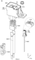
- the connector 12 of the present embodiment comprises a housing 14, a power terminal 290 made of metal, a detection terminal 390 made of metal and a slider 40 made of insulator.
- the housing 14 comprises a main housing 20 made of insulator and a sub-housing 30 made of insulator.
- the present invention is not limited thereto.
- the main housing 20 and the sub-housing 30 may be integral to each other.
- each of the main housing 20 and the sub-housing 30 may be a part of the unitary housing 14.
- the connector 12 may comprise another member in addition to the aforementioned members.
- the main housing 20 has a base portion 212, an opposite portion 214, two side plates 216 and a support plate 218.
- the side plates 216 are located at opposite sides of the main housing 20 in the Y-direction, respectively. Each of the side plates 216 extends in parallel to the XZ-plane.
- the base portion 212 is located at a front end (positive X-side end) of the main housing 20.
- the base portion 212 couples the two side plates 216 to each other in the Y-direction.
- the opposite portion 214 is located in the vicinity of a rear end of the main housing 20.
- the opposite portion 214 couples the two side plates 216 to each other in the Y-direction.
- the support plate 218 is located at an upper side of the main housing 20.
- the support plate 218 extends in parallel to the XY-plane and couples the two side plates 216 to each other in the Y-direction.
- the main housing 20 has an indent 213 and two windows 215.
- the indent 213 is a recess formed in the base portion 212.
- the indent 213 is located at the middle of the base portion 212 in the Y-direction.
- the indent 213 is recessed downward from an upper end of the base portion 212.
- the windows 215 are cuts which are provided so as to correspond to the two side plates 216, respectively.
- Each of the windows 215 is located between the base portion 212 and the corresponding side plate 216 in the X-direction.
- the main housing 20 has two main holding portions 280.
- Each of the main holding portions 280 of the present embodiment is a hole formed in the support plate 218.
- Each of the main holding portions 280 passes through the support plate 218 in the Z-direction.
- the main housing 20 of the present embodiment has the aforementioned basic structure.
- the present invention is not limited thereto, but the basic structure of the main housing 20 can be modified as necessary.
- the power terminal 290 has two blades 292 which are arranged in the Y-direction.
- the main holding portions 280 hold the power terminal 290.
- the blades 292 of the power terminal 290 are inserted into the main holding portions 280, respectively, and are engaged with the main holding portions 280, respectively.
- the power terminal 290 is held by the main housing 20 and is fixed to the main housing 20 so as to be unmovable relative to the main housing 20.
- each of the main holding portions 280 of the present embodiment is a hole which receives the blade 292 of the power terminal 290.
- the structure of each of the main holding portions 280 and the power terminal 290 is not specifically limited, provided that the housing 14 can hold the power terminal 290.
- the housing 14 is provided with two axis portions (bearings) 220.
- the axis portions 220 of the present embodiment are provided to the main housing 20.
- the axis portions 220 are provided so as to correspond to the two side plates 216, respectively.
- Each of the axis portions 220 is a hole which works as a bearing.
- Each of the axis portions 220 passes through the corresponding side plate 216 in the Y-direction and opens rearward.
- the two axis portions 220 are located at positions same as each other in the XZ-plane.
- the connector 12 of the present embodiment is turnable about the mating axis portions 520 and the axis portions 220 when the mating axis portions 520 of the mating connector 16 are combined to the axis portions 220, respectively.
- the connector 12 is turnable about the pivot shafts (mating axis portions) 520 between an open position shown in Fig. 24 and the closed position shown in Fig. 38 via a predetermined position shown in Fig. 28 .
- the connector 12 When the connector 12 is located between the open position and the closed position, the connector 12 is located at an upper side of the mating connector 16 in the upper-lower direction (Z-direction) perpendicular to the axial direction of the pivot shafts 520.
- the connector 12 which is located at the open position is removable from the mating connector 16.
- the connector 12 which is located at the closed position takes the mated state where the connector 12 is completely mated with the mating connector 16.
- the axis portions 220 of the connector 12 are bearings
- the mating axis portions 520 of the mating connector 16 are pivot shafts.
- the present invention is not limited thereto.
- the axis portions 220 may be pivot shafts
- the mating axis portions 520 may be bearings.
- one of the axis portion 220 and the mating axis portion 520 should be a pivot shaft
- a remaining one of the axis portion 220 and the mating axis portion 520 should be a bearing.
- the position of each portion of the connector 12 in the XZ-plane is changed in accordance with the turning movement of the connector 12.
- the position of each portion of the connector 12 in the XZ-plane is a position relative to the connector 12 which is located at the closed position shown in Fig. 38 similarly to the explanation described above.
- the housing 14 is provided with two guide portions 222.
- the guide portions 222 of the present embodiment are provided to the main housing 20.
- the guide portions 222 are provided so as to correspond to the two side plates 216, respectively.
- Each of the guide portions 222 is a channel formed in an outer surface of the corresponding side plate 216 in the Y-direction and is recessed inward in the Y-direction.
- Each of the guide portions 222 has an arc shape which extends about the axis portion 220 in the XZ-plane.
- Each of the guide portions 222 opens at a rear end of the corresponding side plate 216.
- the two guide portions 222 are located at positions same as each other in the XZ-plane.
- the mating guide portions 522 are continuously received in the channels of the guide portions 222, respectively, and are moved along the channels of the guide portions 222, respectively.
- This mechanism prevents the mating axis portions 520 from coming off the axis portions 220 during the turning movement of the connector 12.
- the guide portions 222 and the mating guide portions 522 of the present embodiment enable easy operation of the connector 12 upon the turning movement of the connector 12.
- the present invention is not limited thereto.
- the guide portions 222 and the mating guide portions 522 may be provided as necessary.
- the housing 14 is provided with four slider-guide portions 240 and two slider-support portions 242.
- the slider-guide portions 240 and the slider-support portions 242 of the present embodiment are provided to the main housing 20. More specifically, each of the side plates 216 of the present embodiment is formed with two of the slider-guide portions 240 and one of the slider-support portions 242.
- Each of the slider-guide portions 240 is a recess formed in an inner surface of the side plate 216 in the Y-direction. Each of the slider-guide portions 240 is recessed outward in the Y-direction from the inner surface of the side plate 216. Each of the slider-guide portions 240 is formed with an inner wall surface which is located on an upper side thereof. Each of the inner wall surfaces, which is located on the upper side of the slider-guide portion 240, faces downward. Each of the slider-support portions 242 is a hole formed in the side plate 216. Each of the slider-support portions 242 passes through the side plate 216 in the Y-direction.
- the two slider-guide portions 240 and the slider-support portion 242 are arranged in the X-direction.
- the slider-guide portions 240 and the slider-support portion 242 of one of the side plates 216 are located at positions same as those of the slider-guide portions 240 and the slider-support portion 242 of a remaining one of the side plates 216 in the XZ-plane.
- the housing 14 is provided with two sub-axis portions (pivot shafts) 252.
- the support plate 218 of the main housing 20 is formed with two axis-support portions 250.
- the axis-support portions 250 are located at opposite sides of the support plate 218 in the Y-direction, respectively.
- Each of the axis-support portions 250 has a flat-plate shape in parallel to the XZ-plane and extends downward from the support plate 218.
- the sub-axis portions 252 are provided so as to correspond to the axis-support portions 250, respectively.
- the sub-axis portions 252 are located at positions same as each other in the XZ-plane.
- Each of the sub-axis portions 252 is a projection which has a cylindrical shape projecting inward in the Y-direction from the corresponding axis-support portion 250.
- the two sub-axis portions 252 project toward each other in the Y-direction.
- the housing 14 of the present embodiment is provided with the four slider-guide portions 240, the two slider-support portions 242 and the two sub-axis portions 252.
- Each of these portions has the aforementioned structure and is arranged as described above.
- the present invention is not limited thereto.
- the number, the structure and the arrangement of each of these portions can be modified as necessary.
- the sub-axis portions 252 may be provided as necessary.
- the sub-housing 30 has a rectangular parallelepiped shape.
- the sub-housing 30 has a first abutment surface 312, a second abutment surface 314 and two side walls 316.
- the first abutment surface 312 is a rear part of an upper surface of the sub-housing 30.
- the second abutment surface 314 is a front part of the upper surface of the sub-housing 30.
- the second abutment surface 314 extends in parallel to the XY-plane.
- the first abutment surface 312 is a sloping surface which is oblique to the Z-direction. In detail, the first abutment surface 312 extends downward and rearward from a rear end of the second abutment surface 314.
- the side walls 316 are located at opposite sides of the sub-housing 30 in the Y-direction.
- the sub-housing 30 of the present embodiment has the aforementioned basic structure.
- the present invention is not limited thereto, but the basic structure of the sub-housing 30 can be modified as necessary.
- the sub-housing 30 has a sub-holding portion 380.
- the sub-holding portion 380 of the present embodiment is a hole formed in the sub-housing 30.
- the sub-holding portion 380 opens upward and downward.
- the sub-holding portion 380 is formed with two sub-holding holes 382.
- Each of the sub-holding holes 382 extends downward from the sub-holding portion 380 and opens downward.
- the sub-holding portion 380 holds the detection terminal 390.
- the detection terminal 390 has two pin terminals 392 which are arranged in the Y-direction. Referring to Figs. 21 and 23 together with Fig. 12 , the detection terminal 390 is press-fit into the sub-holding portion 380, and the pin terminals 392 are received in the sub-holding holes 382, respectively. Referring to Fig. 8 together with Fig. 23 , the pin terminals 392 extend downward through the sub-holding holes 382. The thus-located detection terminal 390 is held by the sub-housing 30 and is fixed to the sub-housing 30 so as to be unmovable relative to the sub-housing.
- the sub-holding portion 380 of the present embodiment is a hole for receiving the detection terminal 390.
- the structure of each of the sub-holding portion 380 and the detection terminal 390 is not specifically limited, provided that the housing 14 can hold the detection terminal 390.
- the power terminal 290 of the present embodiment is held by the main housing 20 of the housing 14, and the detection terminal 390 of the present embodiment is held by the sub-housing 30 of the housing 14.
- the present invention is not limited thereto, but the power terminal 290 and the detection terminal 390 should be held by the housing 14.
- the sub-housing 30 is provided with two sub-axis portions (bearings) 320.
- the sub-axis portions 320 are provided so as to correspond to the two side walls 316, respectively.
- Each of the axis portions 220 is a recess which works as a bearing.
- Each of the axis portions 220 is formed in an outer surface of the corresponding side wall 316 in the Y-direction and is recessed inward in the Y-direction.
- Each of the axis portions 220 has a circular shape in the XZ-plane.
- the two sub-axis portions 320 are located at positions same as each other in the XZ-plane.
- connection guided portions 330 are provided so as to correspond to the two side walls 316, respectively.
- Each of the connection guided portions 330 is a channel which is formed in an inner surface of the corresponding side wall 316 in the Y-direction.
- Each of the connection guided portions 330 is recessed outward in the Y-direction from the inner surface of the corresponding side wall 316 and opens upward and downward.
- the two connection guided portions 330 are located at positions same as each other in the XZ-plane.
- each of the connection guided portions 330 is formed with a guided surface 332.
- Each of the guided surfaces 332 is an inner wall surface which is located on a rear side of the connection guided portion 330.
- Each of the guided surfaces 332 extends forward and upward and thereafter extends upward.
- another inner wall surface which is located on a front side of the connection guided portion 330 extends straight along the Z-direction. Therefore, a lower part of each of the connection guided portions 330 extends downward while being widened in the X-direction.
- An upper part of each of the connection guided portions 330 linearly extends along the Z-direction.
- the two sub-axis portions 252 of the main housing 20 are received in the two sub-axis portions 320 of the sub-housing 30, respectively.
- the thus-supported sub-housing 30 is turnable about the sub-axis portions (pivot shafts) 252 relative to the main housing 20.
- the sub-housing 30 is turnable about the sub-axis portions 252 between a first limit position at which the first abutment surface 312 is brought into abutment with the support plate 218 of the main housing 20 and a second limit position at which the second abutment surface 314 is brought into abutment with the support plate 218.
- the sub-housing 30 of the present embodiment is held by the main housing 20 to be swingable.
- the present invention is not limited thereto.
- the sub-housing 30 may be provided as necessary.
- the sub-housing 30 may be fixed to the main housing 20 so as to be unmovable relative to the main housing 20.
- the sub-axis portions 252 of the main housing 20 and the sub-axis portions 320 of the sub-housing 30 do not need to be provided.
- the slider 40 has an end wall 412, a body 416 and two arms 418.
- the end wall 412 is located at a front end of the slider 40.
- the body 416 is located at an upper end of the slider 40 and extends in parallel to the XY-plane as a whole.
- the body 416 extends rearward from a rear end of the end wall 412.
- the arms 418 are located at opposite sides of the slider 40 in the Y-direction, respectively. Each of the arms 418 extends downward from a lower end of the body 416 in parallel to the XZ-plane.
- the end wall 412 has a projecting plate 413.
- the projecting plate 413 is located at an upper end of the end wall 412 and is located at the middle of the end wall 412 in the Y-direction.
- the projecting plate 413 has a flat-plate shape in parallel to the XY-plane and projects forward.
- the projecting plate 413 is formed with two stop projections 415. The stop projections 415 project outward in the Y-direction from opposite side surfaces of the projecting plate 413 in the Y-direction, respectively.
- a lower end of the end wall 412 has a U-like shape in the XY-plane.
- the end wall 412 is provided with an additional portion 414.
- the additional portion 414 is formed on a lower end of the end wall 412 and protrudes downward from the lower end of the end wall 412.
- the end wall 412 has opposite parts in the Y-direction which protrude inward in the Y-direction from the lower end of the end wall 412.
- Each of the arms 418 is provided with a projecting portion 419.
- Each of the projecting portions 419 projects forward from a lower end of the arm 418.
- the slider 40 of the present embodiment has the aforementioned basic structure.
- the present invention is not limited thereto, but the basic structure of the slider 40 can be modified as necessary.
- the slider 40 is provided with four movement-guided portions 420 and two movement-supported portions 422. More specifically, the body 416 has opposite outer side surfaces in the Y-direction. Each of the outer side surfaces is provided with two of the movement-guided portions 420 and one of the movement-supported portions 422. Each of the movement-guided portions 420 and the movement-supported portions 422 is a projection which is formed on the outer side surface of the body 416 in the Y-direction. Each of the movement-guided portions 420 and the movement-supported portions 422 projects outward in the Y-direction. Each of the movement-guided portions 420 has an upper surface which extends in parallel to the XY-plane. Each of the movement-supported portions 422 has an upper surface which is located below the upper surface of each of the movement-guided portions 420 and extends in parallel to the XY-plane.
- each of the outer side surfaces of the body 416 two of the movement-guided portions 420 and the movement-supported portion 422 are arranged in the X-direction.
- the movement-guided portions 420 and the movement-supported portion 422 of one of the outer side surfaces of the body 416 are located at positions same as those of the movement-guided portions 420 and the movement-supported portion 422 of a remaining one of the outer side surfaces of the body 416 in the XZ-plane.
- the four movement-guided portions 420 are formed at positions which correspond to the four slider-guide portions 240 of the main housing 20, respectively. Each of the movement-guided portions 420 is received in the corresponding slider-guide portion 240.
- the two movement-supported portions 422 are formed at positions which correspond to the two slider-support portions 242 of the main housing 20, respectively. Each of the movement-supported portions 422 is received in the corresponding slider-support portion 242.
- the body 416 of the slider 40 is located over the support plate 218 of the main housing 20, and thereby a downward movement of the slider 40 is regulated.
- the upper surface of each of the movement-guided portions 420 is located under the inner wall surface which is located on the upper side of the corresponding slider-guide portion 240.
- the upper surface of each of the movement-supported portions 422 is located under the inner wall surface which is located on the upper side of the corresponding slider-support portion 242. According to this structure, the slider 40 is supported by the main housing 20 so as not to come off the main housing 20.
- each of the movement-guided portions 420 has a size in the X-direction which is smaller than another size of the corresponding slider-guide portion 240 in the X-direction.
- Each of the movement-supported portions 422 has a size in the X-direction which is smaller than another size of the corresponding slider-support portion 242 in the X-direction.
- This structure enables the slider 40 supported by the main housing 20 to be movable relative to the main housing 20 along the X-direction within a predetermined range.
- the connector 12 has a support mechanism which supports the slider 40 to be movable relative to the main housing 20.
- the support mechanism of the present embodiment includes the slider-guide portions 240 and the slider-support portions 242 of the main housing 20 and the movement-guided portions 420 and the movement-supported portions 422 of the slider 40.
- the slider 40 is held by the housing 14 to be movable between a first position and a second position in a slide direction.
- the slide direction is the X-direction in Fig. 11 , for example.
- the first position of the present embodiment is a position at which a rear end of the body 416 of the slider 40 is brought into abutment with a front end of the opposite portion 214 of the main housing 20.
- the second position of the present embodiment is a position at which the end wall 412 of the slider 40 is partially brought into abutment with the base portion 212 of the main housing 20.
- each of the first position and the second position may be defined by another part of the slider 40 and another part of the main housing 20.
- the support mechanism of the slider 40 is not limited to that of the present embodiment.
- the projecting plate 413 of the slider 40 is received in the indent 213 of the main housing 20.
- the two stop projections 415 (see Fig. 17 ) of the projecting plate 413 are pressed against opposite side surfaces of the indent 213 in the Y-direction, respectively.
- the thus-pressed stop projections 415 temporarily stop the slider 40 at the second position when the slider 40 is moved to the second position.
- the stop projections 415 temporarily stop the slider 40 at the first position when the slider 40 is located at the first position.
- the present invention is not limited thereto.
- the projecting plate 413 and the stop projections 415 may be provided as necessary.
- the slider 40 is provided with two first regulated portions 440, two second regulated portions 450 and two abutment portions 460.
- Each of the first regulated portions 440 of the present embodiment is a part of a lower surface of the additional portion 414.
- the second regulated portions 450 of the present embodiment are provided so as to correspond to the two arms 418, respectively.
- Each of the second regulated portions 450 of the present embodiment is a part of an upper surface of the projecting portion 419 of the corresponding arm 418.
- the abutment portions 460 of the present embodiment are provided so as to correspond to the two arms 418, respectively.
- Each of the abutment portions 460 of the present embodiment is a part of a lower surface of the corresponding arm 418.
- the slider 40 is provided with a coupling plate 432 and a lock support portion 434.
- the coupling plate 432 has a flat-plate shape in parallel to the XY-plane and extends rearward from a rear surface of the end wall 412.
- the lock support portion 434 is located rearward of the end wall 412.
- the lock support portion 434 extends along the YZ-plane as a whole except for a lower end part thereof.
- the lock support portion 434 has the lower end part which extends forward.
- the coupling plate 432 has a rear end which is connected to the middle of the lock support portion 434 in the Z-direction. The thus-supported lock support portion 434 is resiliently deformable.
- the lock support portion 434 is formed with two lock projections 436.
- Each of the lock projections 436 is a projection which projects rearward.
- the lock projections 436 are located below a connection portion which is formed between the lock support portion 434 and the coupling plate 432.
- Each of the lock projections 436 has an upper surface which extends in parallel to the XY-plane and works as a lock portion 438.
- the slider 40 is provided with two of the lock portions 438 and the lock support portion 434.
- the lock support portion 434 supports the lock portions 438. When an upper end of the lock support portion 434 is pushed rearward, the lock portions 438 are moved forward.
- the slider 40 is provided with a maintained portion 470.
- the maintained portion 470 of the present embodiment is a rear surface of the lock support portion 434.
- the maintaining portion 558 faces rearward.
- the slider 40 of the present embodiment is provided with the two first regulated portions 440, the two second regulated portions 450, the two abutment portions 460, the two lock portions 438, the lock support portion 434 and the maintained portion 470.
- Each of these portions has the aforementioned structure and is arranged as described above.
- the present invention is not limited thereto.
- the number, the structure and the arrangement of each of these portions can be modified as necessary.
- the number of the first regulated portions 440 may be one or may be three or more.
- Each of the abutment portions 460, the lock portions 438, the lock support portion 434 and the maintained portion 470 may be provided as necessary.
- the connector 12 is attachable to the mating connector 16 along the negative Z-direction from a position above the mating connector 16 under a posture where the connector 12 stands up relative to the mating connector 16.
- the thus-attached connector 12 is located at the open position shown in Figs. 24 to 27 and is partially mated with the mating connector 16.
- the slider 40 is held by the housing 14 to be movable between the first position and the second position in the slide direction in parallel to the radial direction about the pivot shafts 520.
- the slider 40 illustrated in Fig. 27 is located at the first position.
- the connector 12 when the connector 12 is moved to the predetermined position together with the slider 40 which is located at the first position in accordance with a movement of the connector 12 from the open position toward the closed position, the first regulated portions 440 are brought into abutment with the first regulation portions 552, and the connector 12 takes a first regulated state where a movement of the connector 12 toward the closed position beyond the predetermined position is regulated.
- the power terminal 290 is connected to the two mating power terminals 590, and thereby the mating power terminals 590 are connected with each other.
- the detection terminal 390 is not connected to the mating detection terminals 690, and thereby the two signal cables 840 (see Fig. 2 ) are not connected with each other. Therefore, the control by the power system (not shown) makes electric current not flow through the power cables 820 (see Fig. 2 ).
- the slider 40 when the connector 12 is located at the predetermined position, the slider 40 is operable so as to be moved to the second position.
- the first regulated portions 440 of the slider 40 are moved outward in the slide direction which is in parallel to the radial direction to be apart from the first regulation portions 552 of the mating housing 18.
- the first regulated state is released, and the connector 12 is turnable toward the closed position shown in Fig. 38 .
- the first regulated state is released, and the connector 12 is movable to the closed position.
- the connection of the power terminal 290 to the two mating power terminals 590 is kept (see the power terminal 290 illustrated with dashed line).
- the power terminal 290 is connected to the two mating power terminals 590.
- the detection terminal 390 is connected to the two mating detection terminals 690, and thereby the mating detection terminals 690 are connected with each other.
- the connector 12 is under the mated state where it completely mated with the mating connector 16, and the control by the power system (not shown) makes a large current about 100 A flow through the power cables 820 (see Fig. 2 ).
- the connector device 10 connects the power system and the motor (not shown) with each other so that electric power supplied from the power system is transmitted to the motor.
- the lock portions 438 of the slider 40 is brought into abutment with an upper end of the protruding portion 512 of the mating connector 16 in a movement of the connector 12 toward the closed position. Meanwhile, the lock support portion 434 of the slider 40 is resiliently deformed, and the lock portions 438 ride over the mating lock portions 532 of the mating connector 16 to be moved downward. When the connector 12 is moved to the closed position, the lock portions 438 are located under the mating lock portions 532, respectively. As a result, a counterclockwise movement of the connector 12 is prevented, and thereby the connector 12 is kept under the mated state. Thus, the lock portions 438 and the mating lock portions 532 of the present embodiment lock the mated state.
- the lock portions 438 and the mating lock portions 532 of the present embodiment form a lock mechanism which locks the mated state.
- the lock portions 438 of the present embodiment are supported so as to be movable relative to the slider 40.
- the mating lock portions 532 of the present embodiment is fixed so as to be unmovable relative to the mating main housing 50.
- the present invention is not limited thereto.
- the lock portions 438 may be fixed so as to be unmovable relative to the slider 40.
- the mating lock portions 532 may be supported so as to be movable relative to the mating connector 16.
- the lock mechanism may be provided as necessary.
- the maintained portion 470 of the slider 40 is located outward of the maintaining portion 558 of the mating connector 16 in the slide direction which is in parallel to the radial direction, or the X-direction in Fig. 41 .
- the maintained portion 470 is in contact with the maintaining portion 558 or faces the maintaining portion 558 with a slight distance therebetween in the slide direction. Therefore, the slider 40 cannot be moved to the first position.
- the maintained portion 470 is brought into abutment with the maintaining portion 558, and the slider 40 is maintained at the second position.
- Figs. 35 to 38 when the connector 12 is counterclockwise turned along the circumferential direction, the connector 12 is moved from the closed position shown in Fig. 38 to the predetermined position shown in Figs. 35 to 37 .
- Fig. 37 when the connector 12 is moved to the predetermined position, the two second regulated portions 450 of the slider 40 are brought into abutment with the second regulation portions 554 of the mating housing 18, respectively. As a result, a further turn of the connector 12 is temporarily regulated, and the connector 12 is temporarily kept at the predetermined position.
- the second regulated portions 450 are brought into abutment with the second regulation portions 554, and the connector 12 takes a second regulated state where a movement of the connector 12 toward the open position beyond the predetermined position is regulated.
- the slider 40 when the connector 12 is located at the predetermined position, the slider 40 is operable so as to be moved to the first position.
- the two second regulated portions 450 of the slider 40 are moved inward in the slide direction which is in parallel to the radial direction to be apart from the second regulation portions 554 of the mating housing 18.
- the second regulated state is released, and the connector 12 is turnable toward the open position shown in Fig. 24 .
- the second regulated state is released, and the connector 12 is movable to the open position.
- the present embodiment when the connector 12 is located at the predetermined position, the second regulated state is not released unless the slider 40 is moved to the first position.
- the power terminal 290 can be disconnected from the mating power terminals 590 by moving the connector 12 to the open position after the release of the second regulated state.
- the present embodiment provides a sufficiently long period between the disconnection of the detection terminal 390 (see Fig. 33 ) and the disconnection of the power terminal 290.
- an operator can touch the power terminal 290 and the mating power terminals 590 only when the sufficiently long period has passed after the stop of the electric current. Therefore, electric shock of the operator can be prevented.
- the present embodiment also provides a sufficiently long period between the connection of the power terminal 290 and the connection of the detection terminal 390 (see Fig. 33 ). According to the present embodiment, damage of the power terminal 290 which might be caused because of arc discharge can be prevented, for example.
- the slider 40 which is used to release the movement regulation is arranged above the housing 14.
- the slider 40 does not need to be provided on an outer end of the housing 14 in the radial direction. Therefore, the connector 12 can be reduced in size.
- the present embodiment provides the connector device 10 which is configured to provide the sufficiently long period between disconnection of the detection terminal 390 (see Fig. 33 ) and disconnection of the power terminal 290 and which enables the connector 12 to be reduced in size.
- the maintained portion 470 and the maintaining portion 558 of the present embodiment prevent a movement of the slider 40 to the first position when the connector 12 is located at the closed position. If the slider 40 of the connector 12 which is located at the closed position is movable to the first position, an irregular operation might move the connector 12 to the open position without placing the connector 12 under the aforementioned second regulated state. In contrast, the connector 12 of the present embodiment reliably takes the second regulated state in a movement of the connector 12 from the closed position to the open position.
- the present invention is not limited thereto.
- the maintained portion 470 and the maintaining portion 558 may be provided as necessary.
- the abutment portions 460 (see dashed line in Fig. 37 ) of the slider 40 are brought into abutment with the catch portions 556 of the mating housing 18, respectively.
- the abutment portions 460 extend rearward and downward similarly to the catch portions 556.
- the abutment portions 460 which are brought into abutment with the sloping surfaces of the catch portions 556 receive a rearward force.
- the slider 40 is moved to the first position, and thereafter the first regulated portions 440 of the slider 40 are brought into abutment with the first regulation portions 552 of the mating housing 18, respectively.
- the connector 12 when the connector 12 is moved from the open position toward the closed position together with the slider 40 which is located at the second position, the abutment portions 460 are brought into abutment with the catch portions 556, and the slider 40 is moved to the first position.
- the connector 12 because the abutment portions 460 and the catch portions 556 are provided, the connector 12 reliably takes the aforementioned first regulated state in accordance with a movement of the connector 12 from the open position to the closed position.
- the present invention is not limited thereto.
- the abutment portions 460 and the catch portions 556 may be provided as necessary.
- the position of the first regulated portions 440 of the slider 40 can be visually recognized through the windows 215 of the main housing 20. Therefore, the operator can easily perform a proper operation while visually recognizing the position of the first regulated portions 440.
- the present invention is not limited thereto.
- the windows 215 may be provided as necessary.
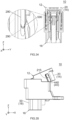
- the sub-housing 30 when the connector 12 is located at the open position, the sub-housing 30 is located at the first limit position in which the first abutment surface 312 of the sub-housing 30 is in abutment with the support plate 218 of the main housing 20.
- the connection-guide portions 562 of the mating connector 16 when the connector 12 is moved from the open position to the predetermined position, the connection-guide portions 562 of the mating connector 16 are brought into abutment with the guided surfaces 332 of the sub-housing 30, respectively, and thereafter are moved along the guided surfaces 332. In other words, the guided surfaces 332 are moved downward while being in contact with the connection-guide portions 562.
- the sub-housing 30 is turned toward the second limit position (see the sub-housing 30 illustrated with dashed line in Fig. 32 ). While the connector 12 is moved from the predetermined position to the closed position, the turning movement of the sub-housing 30 toward the second limit position continues.
- connection-guide portions 562 of the present embodiment guide the connection guided portions 330 to adjust a posture of the sub-housing 30 so that the detection terminal 390 is connected to the mating detection terminals 690.
- the present invention is not limited thereto.
- the connection-guide portions 562 and the connection guided portions 330 may be provided as necessary.
Landscapes
- Details Of Connecting Devices For Male And Female Coupling (AREA)
Applications Claiming Priority (1)
| Application Number | Priority Date | Filing Date | Title |
|---|---|---|---|
| JP2020216465A JP7507084B2 (ja) | 2020-12-25 | 2020-12-25 | コネクタ装置 |
Publications (2)
| Publication Number | Publication Date |
|---|---|
| EP4020722A1 EP4020722A1 (en) | 2022-06-29 |
| EP4020722B1 true EP4020722B1 (en) | 2024-07-24 |
Family
ID=78414280
Family Applications (1)
| Application Number | Title | Priority Date | Filing Date |
|---|---|---|---|
| EP21205144.5A Active EP4020722B1 (en) | 2020-12-25 | 2021-10-28 | Connector device |
Country Status (4)
| Country | Link |
|---|---|
| US (1) | US11476065B2 (https=) |
| EP (1) | EP4020722B1 (https=) |
| JP (1) | JP7507084B2 (https=) |
| CN (1) | CN114696160B (https=) |
Families Citing this family (4)
| Publication number | Priority date | Publication date | Assignee | Title |
|---|---|---|---|---|
| JP7638845B2 (ja) * | 2021-10-06 | 2025-03-04 | 日本航空電子工業株式会社 | コネクタ装置 |
| USD1066253S1 (en) * | 2022-02-14 | 2025-03-11 | Techtronic Cordless Gp | Harness plug |
| JP1742942S (ja) * | 2022-09-06 | 2023-04-26 | コネクタ | |
| JP2024073262A (ja) * | 2022-11-17 | 2024-05-29 | 日本航空電子工業株式会社 | コネクタ装置 |
Family Cites Families (12)
| Publication number | Priority date | Publication date | Assignee | Title |
|---|---|---|---|---|
| DE102012218034B4 (de) | 2012-10-02 | 2025-06-12 | Robert Bosch Gmbh | Steckverbindung |
| JP2014238929A (ja) * | 2013-06-06 | 2014-12-18 | 日本航空電子工業株式会社 | コネクタ装置 |
| JP6099203B2 (ja) * | 2013-09-03 | 2017-03-22 | 日本航空電子工業株式会社 | コネクタ装置 |
| JP6182515B2 (ja) | 2014-08-19 | 2017-08-16 | 日本航空電子工業株式会社 | コネクタ装置 |
| JP6482077B2 (ja) | 2015-09-02 | 2019-03-13 | 日本航空電子工業株式会社 | コネクタ装置 |
| JP6663790B2 (ja) * | 2016-05-12 | 2020-03-13 | 日本航空電子工業株式会社 | コネクタ装置 |
| JP6634347B2 (ja) * | 2016-06-20 | 2020-01-22 | 日本航空電子工業株式会社 | 電源回路遮断装置 |
| JP6692718B2 (ja) | 2016-08-16 | 2020-05-13 | 日本航空電子工業株式会社 | コネクタ装置 |
| JP6720061B2 (ja) | 2016-11-18 | 2020-07-08 | 日本航空電子工業株式会社 | コネクタ装置 |
| JP6840640B2 (ja) * | 2017-08-18 | 2021-03-10 | 日本航空電子工業株式会社 | コネクタ装置 |
| JP6910899B2 (ja) * | 2017-09-08 | 2021-07-28 | タイコエレクトロニクスジャパン合同会社 | コネクタおよびコネクタ組立体 |
| JP7010886B2 (ja) * | 2019-06-06 | 2022-01-26 | 矢崎総業株式会社 | コネクタ及び電源回路遮断装置 |
-
2020
- 2020-12-25 JP JP2020216465A patent/JP7507084B2/ja active Active
-
2021
- 2021-10-25 US US17/509,193 patent/US11476065B2/en active Active
- 2021-10-28 EP EP21205144.5A patent/EP4020722B1/en active Active
- 2021-11-08 CN CN202111316610.9A patent/CN114696160B/zh active Active
Also Published As
| Publication number | Publication date |
|---|---|
| CN114696160B (zh) | 2024-03-12 |
| JP7507084B2 (ja) | 2024-06-27 |
| US11476065B2 (en) | 2022-10-18 |
| EP4020722A1 (en) | 2022-06-29 |
| JP2022102010A (ja) | 2022-07-07 |
| CN114696160A (zh) | 2022-07-01 |
| US20220208486A1 (en) | 2022-06-30 |
Similar Documents
| Publication | Publication Date | Title |
|---|---|---|
| EP4020722B1 (en) | Connector device | |
| EP3444906B1 (en) | Connector device | |
| US10008805B2 (en) | Connector device | |
| US9966701B2 (en) | Connector device | |
| CN107369978B (zh) | 连接器装置 | |
| EP2843773B1 (en) | Connector device | |
| US8915749B2 (en) | Power source circuit shutoff device | |
| US10008804B2 (en) | Connector device | |
| EP1296341B1 (en) | Lever fitting-type manual disconnector | |
| EP0624925A1 (en) | Connector with fitting detection function | |
| US9905965B2 (en) | Connector and connector assembly | |
| US20170093088A1 (en) | Connector and connector assembly | |
| US5575678A (en) | Locking connector | |
| US5876228A (en) | Connector connecting structure | |
| EP4203200A1 (en) | Charging connector | |
| EP3782847A1 (en) | Automatic coupler assembly | |
| US20240145971A1 (en) | Electrical connector and switching device | |
| EP3404776B1 (en) | Lever fitting-type connector | |
| US20240170890A1 (en) | Connector device | |
| CN219144655U (zh) | 电插座和电插头 | |
| US20250007213A1 (en) | Connector and connector assembly |
Legal Events
| Date | Code | Title | Description |
|---|---|---|---|
| PUAI | Public reference made under article 153(3) epc to a published international application that has entered the european phase |
Free format text: ORIGINAL CODE: 0009012 |
|
| STAA | Information on the status of an ep patent application or granted ep patent |
Free format text: STATUS: THE APPLICATION HAS BEEN PUBLISHED |
|
| AK | Designated contracting states |
Kind code of ref document: A1 Designated state(s): AL AT BE BG CH CY CZ DE DK EE ES FI FR GB GR HR HU IE IS IT LI LT LU LV MC MK MT NL NO PL PT RO RS SE SI SK SM TR |
|
| STAA | Information on the status of an ep patent application or granted ep patent |
Free format text: STATUS: REQUEST FOR EXAMINATION WAS MADE |
|
| 17P | Request for examination filed |
Effective date: 20221202 |
|
| RBV | Designated contracting states (corrected) |
Designated state(s): AL AT BE BG CH CY CZ DE DK EE ES FI FR GB GR HR HU IE IS IT LI LT LU LV MC MK MT NL NO PL PT RO RS SE SI SK SM TR |
|
| STAA | Information on the status of an ep patent application or granted ep patent |
Free format text: STATUS: EXAMINATION IS IN PROGRESS |
|
| 17Q | First examination report despatched |
Effective date: 20230227 |
|
| GRAP | Despatch of communication of intention to grant a patent |
Free format text: ORIGINAL CODE: EPIDOSNIGR1 |
|
| STAA | Information on the status of an ep patent application or granted ep patent |
Free format text: STATUS: GRANT OF PATENT IS INTENDED |
|
| RIC1 | Information provided on ipc code assigned before grant |
Ipc: H01R 13/629 20060101ALN20240205BHEP Ipc: H01R 13/70 20060101ALN20240205BHEP Ipc: H01R 24/00 20110101AFI20240205BHEP |
|
| INTG | Intention to grant announced |
Effective date: 20240221 |
|
| RAP3 | Party data changed (applicant data changed or rights of an application transferred) |
Owner name: JAPAN AVIATION ELECTRONICS INDUSTRY, LIMITED |
|
| GRAS | Grant fee paid |
Free format text: ORIGINAL CODE: EPIDOSNIGR3 |
|
| GRAA | (expected) grant |
Free format text: ORIGINAL CODE: 0009210 |
|
| STAA | Information on the status of an ep patent application or granted ep patent |
Free format text: STATUS: THE PATENT HAS BEEN GRANTED |
|
| AK | Designated contracting states |
Kind code of ref document: B1 Designated state(s): AL AT BE BG CH CY CZ DE DK EE ES FI FR GB GR HR HU IE IS IT LI LT LU LV MC MK MT NL NO PL PT RO RS SE SI SK SM TR |
|
| REG | Reference to a national code |
Ref country code: GB Ref legal event code: FG4D |
|
| REG | Reference to a national code |
Ref country code: CH Ref legal event code: EP |
|
| REG | Reference to a national code |
Ref country code: DE Ref legal event code: R096 Ref document number: 602021016063 Country of ref document: DE |
|
| REG | Reference to a national code |
Ref country code: IE Ref legal event code: FG4D |
|
| RAP4 | Party data changed (patent owner data changed or rights of a patent transferred) |
Owner name: JAPAN AVIATION ELECTRONICS INDUSTRY, LIMITED |
|
| REG | Reference to a national code |
Ref country code: LT Ref legal event code: MG9D |
|
| REG | Reference to a national code |
Ref country code: NL Ref legal event code: MP Effective date: 20240724 |
|
| PG25 | Lapsed in a contracting state [announced via postgrant information from national office to epo] |
Ref country code: PT Free format text: LAPSE BECAUSE OF FAILURE TO SUBMIT A TRANSLATION OF THE DESCRIPTION OR TO PAY THE FEE WITHIN THE PRESCRIBED TIME-LIMIT Effective date: 20241125 |
|
| REG | Reference to a national code |
Ref country code: AT Ref legal event code: MK05 Ref document number: 1707194 Country of ref document: AT Kind code of ref document: T Effective date: 20240724 |
|
| PG25 | Lapsed in a contracting state [announced via postgrant information from national office to epo] |
Ref country code: NL Free format text: LAPSE BECAUSE OF FAILURE TO SUBMIT A TRANSLATION OF THE DESCRIPTION OR TO PAY THE FEE WITHIN THE PRESCRIBED TIME-LIMIT Effective date: 20240724 |
|
| PG25 | Lapsed in a contracting state [announced via postgrant information from national office to epo] |
Ref country code: PT Free format text: LAPSE BECAUSE OF FAILURE TO SUBMIT A TRANSLATION OF THE DESCRIPTION OR TO PAY THE FEE WITHIN THE PRESCRIBED TIME-LIMIT Effective date: 20241125 Ref country code: NL Free format text: LAPSE BECAUSE OF FAILURE TO SUBMIT A TRANSLATION OF THE DESCRIPTION OR TO PAY THE FEE WITHIN THE PRESCRIBED TIME-LIMIT Effective date: 20240724 |
|
| PG25 | Lapsed in a contracting state [announced via postgrant information from national office to epo] |
Ref country code: NO Free format text: LAPSE BECAUSE OF FAILURE TO SUBMIT A TRANSLATION OF THE DESCRIPTION OR TO PAY THE FEE WITHIN THE PRESCRIBED TIME-LIMIT Effective date: 20241024 |
|
| PG25 | Lapsed in a contracting state [announced via postgrant information from national office to epo] |
Ref country code: FI Free format text: LAPSE BECAUSE OF FAILURE TO SUBMIT A TRANSLATION OF THE DESCRIPTION OR TO PAY THE FEE WITHIN THE PRESCRIBED TIME-LIMIT Effective date: 20240724 Ref country code: PL Free format text: LAPSE BECAUSE OF FAILURE TO SUBMIT A TRANSLATION OF THE DESCRIPTION OR TO PAY THE FEE WITHIN THE PRESCRIBED TIME-LIMIT Effective date: 20240724 Ref country code: GR Free format text: LAPSE BECAUSE OF FAILURE TO SUBMIT A TRANSLATION OF THE DESCRIPTION OR TO PAY THE FEE WITHIN THE PRESCRIBED TIME-LIMIT Effective date: 20241025 |
|
| PG25 | Lapsed in a contracting state [announced via postgrant information from national office to epo] |
Ref country code: BG Free format text: LAPSE BECAUSE OF FAILURE TO SUBMIT A TRANSLATION OF THE DESCRIPTION OR TO PAY THE FEE WITHIN THE PRESCRIBED TIME-LIMIT Effective date: 20240724 |
|
| PG25 | Lapsed in a contracting state [announced via postgrant information from national office to epo] |
Ref country code: LV Free format text: LAPSE BECAUSE OF FAILURE TO SUBMIT A TRANSLATION OF THE DESCRIPTION OR TO PAY THE FEE WITHIN THE PRESCRIBED TIME-LIMIT Effective date: 20240724 |
|
| PG25 | Lapsed in a contracting state [announced via postgrant information from national office to epo] |
Ref country code: IS Free format text: LAPSE BECAUSE OF FAILURE TO SUBMIT A TRANSLATION OF THE DESCRIPTION OR TO PAY THE FEE WITHIN THE PRESCRIBED TIME-LIMIT Effective date: 20241124 Ref country code: AT Free format text: LAPSE BECAUSE OF FAILURE TO SUBMIT A TRANSLATION OF THE DESCRIPTION OR TO PAY THE FEE WITHIN THE PRESCRIBED TIME-LIMIT Effective date: 20240724 |
|
| PG25 | Lapsed in a contracting state [announced via postgrant information from national office to epo] |
Ref country code: HR Free format text: LAPSE BECAUSE OF FAILURE TO SUBMIT A TRANSLATION OF THE DESCRIPTION OR TO PAY THE FEE WITHIN THE PRESCRIBED TIME-LIMIT Effective date: 20240724 |
|
| PG25 | Lapsed in a contracting state [announced via postgrant information from national office to epo] |
Ref country code: RS Free format text: LAPSE BECAUSE OF FAILURE TO SUBMIT A TRANSLATION OF THE DESCRIPTION OR TO PAY THE FEE WITHIN THE PRESCRIBED TIME-LIMIT Effective date: 20241024 Ref country code: ES Free format text: LAPSE BECAUSE OF FAILURE TO SUBMIT A TRANSLATION OF THE DESCRIPTION OR TO PAY THE FEE WITHIN THE PRESCRIBED TIME-LIMIT Effective date: 20240724 |
|
| PG25 | Lapsed in a contracting state [announced via postgrant information from national office to epo] |
Ref country code: RS Free format text: LAPSE BECAUSE OF FAILURE TO SUBMIT A TRANSLATION OF THE DESCRIPTION OR TO PAY THE FEE WITHIN THE PRESCRIBED TIME-LIMIT Effective date: 20241024 Ref country code: PL Free format text: LAPSE BECAUSE OF FAILURE TO SUBMIT A TRANSLATION OF THE DESCRIPTION OR TO PAY THE FEE WITHIN THE PRESCRIBED TIME-LIMIT Effective date: 20240724 Ref country code: NO Free format text: LAPSE BECAUSE OF FAILURE TO SUBMIT A TRANSLATION OF THE DESCRIPTION OR TO PAY THE FEE WITHIN THE PRESCRIBED TIME-LIMIT Effective date: 20241024 Ref country code: LV Free format text: LAPSE BECAUSE OF FAILURE TO SUBMIT A TRANSLATION OF THE DESCRIPTION OR TO PAY THE FEE WITHIN THE PRESCRIBED TIME-LIMIT Effective date: 20240724 Ref country code: IS Free format text: LAPSE BECAUSE OF FAILURE TO SUBMIT A TRANSLATION OF THE DESCRIPTION OR TO PAY THE FEE WITHIN THE PRESCRIBED TIME-LIMIT Effective date: 20241124 Ref country code: HR Free format text: LAPSE BECAUSE OF FAILURE TO SUBMIT A TRANSLATION OF THE DESCRIPTION OR TO PAY THE FEE WITHIN THE PRESCRIBED TIME-LIMIT Effective date: 20240724 Ref country code: GR Free format text: LAPSE BECAUSE OF FAILURE TO SUBMIT A TRANSLATION OF THE DESCRIPTION OR TO PAY THE FEE WITHIN THE PRESCRIBED TIME-LIMIT Effective date: 20241025 Ref country code: FI Free format text: LAPSE BECAUSE OF FAILURE TO SUBMIT A TRANSLATION OF THE DESCRIPTION OR TO PAY THE FEE WITHIN THE PRESCRIBED TIME-LIMIT Effective date: 20240724 Ref country code: ES Free format text: LAPSE BECAUSE OF FAILURE TO SUBMIT A TRANSLATION OF THE DESCRIPTION OR TO PAY THE FEE WITHIN THE PRESCRIBED TIME-LIMIT Effective date: 20240724 Ref country code: BG Free format text: LAPSE BECAUSE OF FAILURE TO SUBMIT A TRANSLATION OF THE DESCRIPTION OR TO PAY THE FEE WITHIN THE PRESCRIBED TIME-LIMIT Effective date: 20240724 Ref country code: AT Free format text: LAPSE BECAUSE OF FAILURE TO SUBMIT A TRANSLATION OF THE DESCRIPTION OR TO PAY THE FEE WITHIN THE PRESCRIBED TIME-LIMIT Effective date: 20240724 |
|
| PG25 | Lapsed in a contracting state [announced via postgrant information from national office to epo] |
Ref country code: RO Free format text: LAPSE BECAUSE OF FAILURE TO SUBMIT A TRANSLATION OF THE DESCRIPTION OR TO PAY THE FEE WITHIN THE PRESCRIBED TIME-LIMIT Effective date: 20240724 Ref country code: SM Free format text: LAPSE BECAUSE OF FAILURE TO SUBMIT A TRANSLATION OF THE DESCRIPTION OR TO PAY THE FEE WITHIN THE PRESCRIBED TIME-LIMIT Effective date: 20240724 Ref country code: DK Free format text: LAPSE BECAUSE OF FAILURE TO SUBMIT A TRANSLATION OF THE DESCRIPTION OR TO PAY THE FEE WITHIN THE PRESCRIBED TIME-LIMIT Effective date: 20240724 |
|
| PG25 | Lapsed in a contracting state [announced via postgrant information from national office to epo] |
Ref country code: EE Free format text: LAPSE BECAUSE OF FAILURE TO SUBMIT A TRANSLATION OF THE DESCRIPTION OR TO PAY THE FEE WITHIN THE PRESCRIBED TIME-LIMIT Effective date: 20240724 |
|
| PG25 | Lapsed in a contracting state [announced via postgrant information from national office to epo] |
Ref country code: CZ Free format text: LAPSE BECAUSE OF FAILURE TO SUBMIT A TRANSLATION OF THE DESCRIPTION OR TO PAY THE FEE WITHIN THE PRESCRIBED TIME-LIMIT Effective date: 20240724 |
|
| REG | Reference to a national code |
Ref country code: DE Ref legal event code: R097 Ref document number: 602021016063 Country of ref document: DE |
|
| PG25 | Lapsed in a contracting state [announced via postgrant information from national office to epo] |
Ref country code: IT Free format text: LAPSE BECAUSE OF FAILURE TO SUBMIT A TRANSLATION OF THE DESCRIPTION OR TO PAY THE FEE WITHIN THE PRESCRIBED TIME-LIMIT Effective date: 20240724 Ref country code: SK Free format text: LAPSE BECAUSE OF FAILURE TO SUBMIT A TRANSLATION OF THE DESCRIPTION OR TO PAY THE FEE WITHIN THE PRESCRIBED TIME-LIMIT Effective date: 20240724 |
|
| PLBE | No opposition filed within time limit |
Free format text: ORIGINAL CODE: 0009261 |
|
| STAA | Information on the status of an ep patent application or granted ep patent |
Free format text: STATUS: NO OPPOSITION FILED WITHIN TIME LIMIT |
|
| REG | Reference to a national code |
Ref country code: CH Ref legal event code: PL |
|
| 26N | No opposition filed |
Effective date: 20250425 |
|
| PG25 | Lapsed in a contracting state [announced via postgrant information from national office to epo] |
Ref country code: MC Free format text: LAPSE BECAUSE OF FAILURE TO SUBMIT A TRANSLATION OF THE DESCRIPTION OR TO PAY THE FEE WITHIN THE PRESCRIBED TIME-LIMIT Effective date: 20240724 |
|
| PG25 | Lapsed in a contracting state [announced via postgrant information from national office to epo] |
Ref country code: LU Free format text: LAPSE BECAUSE OF NON-PAYMENT OF DUE FEES Effective date: 20241028 Ref country code: BE Free format text: LAPSE BECAUSE OF NON-PAYMENT OF DUE FEES Effective date: 20241031 |
|
| PG25 | Lapsed in a contracting state [announced via postgrant information from national office to epo] |
Ref country code: FR Free format text: LAPSE BECAUSE OF NON-PAYMENT OF DUE FEES Effective date: 20241031 |
|
| PG25 | Lapsed in a contracting state [announced via postgrant information from national office to epo] |
Ref country code: CH Free format text: LAPSE BECAUSE OF NON-PAYMENT OF DUE FEES Effective date: 20241031 |
|
| REG | Reference to a national code |
Ref country code: BE Ref legal event code: MM Effective date: 20241031 |
|
| PG25 | Lapsed in a contracting state [announced via postgrant information from national office to epo] |
Ref country code: SE Free format text: LAPSE BECAUSE OF FAILURE TO SUBMIT A TRANSLATION OF THE DESCRIPTION OR TO PAY THE FEE WITHIN THE PRESCRIBED TIME-LIMIT Effective date: 20240724 |
|
| PG25 | Lapsed in a contracting state [announced via postgrant information from national office to epo] |
Ref country code: IE Free format text: LAPSE BECAUSE OF NON-PAYMENT OF DUE FEES Effective date: 20241028 |
|
| PGFP | Annual fee paid to national office [announced via postgrant information from national office to epo] |
Ref country code: DE Payment date: 20250902 Year of fee payment: 5 |
|
| PG25 | Lapsed in a contracting state [announced via postgrant information from national office to epo] |
Ref country code: HU Free format text: LAPSE BECAUSE OF FAILURE TO SUBMIT A TRANSLATION OF THE DESCRIPTION OR TO PAY THE FEE WITHIN THE PRESCRIBED TIME-LIMIT; INVALID AB INITIO Effective date: 20211028 |
|
| PG25 | Lapsed in a contracting state [announced via postgrant information from national office to epo] |
Ref country code: CY Free format text: LAPSE BECAUSE OF FAILURE TO SUBMIT A TRANSLATION OF THE DESCRIPTION OR TO PAY THE FEE WITHIN THE PRESCRIBED TIME-LIMIT; INVALID AB INITIO Effective date: 20211028 |