EP4020692A1 - Electrochemical device and electronic device - Google Patents
Electrochemical device and electronic device Download PDFInfo
- Publication number
- EP4020692A1 EP4020692A1 EP20943015.6A EP20943015A EP4020692A1 EP 4020692 A1 EP4020692 A1 EP 4020692A1 EP 20943015 A EP20943015 A EP 20943015A EP 4020692 A1 EP4020692 A1 EP 4020692A1
- Authority
- EP
- European Patent Office
- Prior art keywords
- barrier
- electrode assembly
- electrochemical apparatus
- thickness
- layer
- Prior art date
- Legal status (The legal status is an assumption and is not a legal conclusion. Google has not performed a legal analysis and makes no representation as to the accuracy of the status listed.)
- Pending
Links
- 230000004888 barrier function Effects 0.000 claims abstract description 128
- 238000007789 sealing Methods 0.000 claims abstract description 86
- 230000000712 assembly Effects 0.000 claims abstract description 43
- 238000000429 assembly Methods 0.000 claims abstract description 43
- XLYOFNOQVPJJNP-UHFFFAOYSA-N water Substances O XLYOFNOQVPJJNP-UHFFFAOYSA-N 0.000 claims abstract description 43
- 239000003792 electrolyte Substances 0.000 claims abstract description 37
- 230000035699 permeability Effects 0.000 claims abstract description 23
- 239000010410 layer Substances 0.000 claims description 173
- 150000002500 ions Chemical class 0.000 claims description 72
- -1 polyethylene terephthalate Polymers 0.000 claims description 67
- 229910052782 aluminium Inorganic materials 0.000 claims description 37
- 239000004743 Polypropylene Substances 0.000 claims description 34
- 239000000463 material Substances 0.000 claims description 32
- 239000010408 film Substances 0.000 claims description 25
- 238000002844 melting Methods 0.000 claims description 25
- 230000008018 melting Effects 0.000 claims description 25
- OKTJSMMVPCPJKN-UHFFFAOYSA-N Carbon Chemical compound [C] OKTJSMMVPCPJKN-UHFFFAOYSA-N 0.000 claims description 20
- 239000004698 Polyethylene Substances 0.000 claims description 18
- 229920000573 polyethylene Polymers 0.000 claims description 18
- 239000002861 polymer material Substances 0.000 claims description 18
- 229920001155 polypropylene Polymers 0.000 claims description 17
- 239000004952 Polyamide Substances 0.000 claims description 9
- 239000007769 metal material Substances 0.000 claims description 9
- 229920002647 polyamide Polymers 0.000 claims description 9
- 229910052799 carbon Inorganic materials 0.000 claims description 8
- 239000002033 PVDF binder Substances 0.000 claims description 7
- 239000003575 carbonaceous material Substances 0.000 claims description 7
- 229920000728 polyester Polymers 0.000 claims description 7
- 229920002635 polyurethane Polymers 0.000 claims description 7
- 239000004814 polyurethane Substances 0.000 claims description 7
- 238000004804 winding Methods 0.000 claims description 7
- 229920000089 Cyclic olefin copolymer Polymers 0.000 claims description 6
- 229920000219 Ethylene vinyl alcohol Polymers 0.000 claims description 6
- 239000004721 Polyphenylene oxide Substances 0.000 claims description 6
- 239000004793 Polystyrene Substances 0.000 claims description 6
- 229920006242 ethylene acrylic acid copolymer Polymers 0.000 claims description 6
- 229920006244 ethylene-ethyl acrylate Polymers 0.000 claims description 6
- 239000000203 mixture Substances 0.000 claims description 6
- 150000002825 nitriles Chemical class 0.000 claims description 6
- 229920003207 poly(ethylene-2,6-naphthalate) Polymers 0.000 claims description 6
- 229920000570 polyether Polymers 0.000 claims description 6
- 239000011112 polyethylene naphthalate Substances 0.000 claims description 6
- 229920002223 polystyrene Polymers 0.000 claims description 6
- 239000004800 polyvinyl chloride Substances 0.000 claims description 6
- 229920000915 polyvinyl chloride Polymers 0.000 claims description 6
- 229920002981 polyvinylidene fluoride Polymers 0.000 claims description 6
- 239000004711 α-olefin Substances 0.000 claims description 6
- 229910021389 graphene Inorganic materials 0.000 claims description 5
- 229920001343 polytetrafluoroethylene Polymers 0.000 claims description 5
- 239000004810 polytetrafluoroethylene Substances 0.000 claims description 5
- 239000004642 Polyimide Substances 0.000 claims description 4
- 150000008065 acid anhydrides Chemical class 0.000 claims description 4
- 229910052802 copper Inorganic materials 0.000 claims description 4
- 229910052759 nickel Inorganic materials 0.000 claims description 4
- 239000005020 polyethylene terephthalate Substances 0.000 claims description 4
- 229920000139 polyethylene terephthalate Polymers 0.000 claims description 4
- 229920001721 polyimide Polymers 0.000 claims description 4
- 229920001955 polyphenylene ether Polymers 0.000 claims description 4
- 229910052709 silver Inorganic materials 0.000 claims description 4
- UPZFLZYXYGBAPL-UHFFFAOYSA-N 2-ethyl-2-methyl-1,3-dioxolane Chemical compound CCC1(C)OCCO1 UPZFLZYXYGBAPL-UHFFFAOYSA-N 0.000 claims description 3
- XMWRBQBLMFGWIX-UHFFFAOYSA-N C60 fullerene Chemical compound C12=C3C(C4=C56)=C7C8=C5C5=C9C%10=C6C6=C4C1=C1C4=C6C6=C%10C%10=C9C9=C%11C5=C8C5=C8C7=C3C3=C7C2=C1C1=C2C4=C6C4=C%10C6=C9C9=C%11C5=C5C8=C3C3=C7C1=C1C2=C4C6=C2C9=C5C3=C12 XMWRBQBLMFGWIX-UHFFFAOYSA-N 0.000 claims description 3
- 239000004696 Poly ether ether ketone Substances 0.000 claims description 3
- 239000004962 Polyamide-imide Substances 0.000 claims description 3
- 239000002202 Polyethylene glycol Substances 0.000 claims description 3
- 239000004734 Polyphenylene sulfide Substances 0.000 claims description 3
- 229920002978 Vinylon Polymers 0.000 claims description 3
- 239000006230 acetylene black Substances 0.000 claims description 3
- 229910045601 alloy Inorganic materials 0.000 claims description 3
- 239000000956 alloy Substances 0.000 claims description 3
- 150000001412 amines Chemical class 0.000 claims description 3
- 150000008064 anhydrides Chemical class 0.000 claims description 3
- 229910052787 antimony Inorganic materials 0.000 claims description 3
- 229910052791 calcium Inorganic materials 0.000 claims description 3
- 229910052804 chromium Inorganic materials 0.000 claims description 3
- 125000004122 cyclic group Chemical group 0.000 claims description 3
- 150000002148 esters Chemical class 0.000 claims description 3
- 229920001038 ethylene copolymer Polymers 0.000 claims description 3
- 239000005038 ethylene vinyl acetate Substances 0.000 claims description 3
- 229910003472 fullerene Inorganic materials 0.000 claims description 3
- 229910052732 germanium Inorganic materials 0.000 claims description 3
- 229910052737 gold Inorganic materials 0.000 claims description 3
- 229910002804 graphite Inorganic materials 0.000 claims description 3
- 239000010439 graphite Substances 0.000 claims description 3
- 229910052738 indium Inorganic materials 0.000 claims description 3
- 229910052742 iron Inorganic materials 0.000 claims description 3
- 229910052745 lead Inorganic materials 0.000 claims description 3
- 229910052749 magnesium Inorganic materials 0.000 claims description 3
- 229910052750 molybdenum Inorganic materials 0.000 claims description 3
- 229910052697 platinum Inorganic materials 0.000 claims description 3
- 229920002492 poly(sulfone) Polymers 0.000 claims description 3
- 229920002312 polyamide-imide Polymers 0.000 claims description 3
- 229920001707 polybutylene terephthalate Polymers 0.000 claims description 3
- 229920000515 polycarbonate Polymers 0.000 claims description 3
- 239000004417 polycarbonate Substances 0.000 claims description 3
- 229920002530 polyetherether ketone Polymers 0.000 claims description 3
- 229920001223 polyethylene glycol Polymers 0.000 claims description 3
- 229920000098 polyolefin Polymers 0.000 claims description 3
- 229920000069 polyphenylene sulfide Polymers 0.000 claims description 3
- 229920000379 polypropylene carbonate Polymers 0.000 claims description 3
- 229920001296 polysiloxane Polymers 0.000 claims description 3
- 229920002689 polyvinyl acetate Polymers 0.000 claims description 3
- 239000011118 polyvinyl acetate Substances 0.000 claims description 3
- 229920000131 polyvinylidene Polymers 0.000 claims description 3
- 229910052700 potassium Inorganic materials 0.000 claims description 3
- 239000002356 single layer Substances 0.000 claims description 3
- 229910052708 sodium Inorganic materials 0.000 claims description 3
- 239000010935 stainless steel Substances 0.000 claims description 3
- 229910001220 stainless steel Inorganic materials 0.000 claims description 3
- 229910052712 strontium Inorganic materials 0.000 claims description 3
- 229910052719 titanium Inorganic materials 0.000 claims description 3
- 229910052721 tungsten Inorganic materials 0.000 claims description 3
- 229910052725 zinc Inorganic materials 0.000 claims description 3
- 239000011701 zinc Substances 0.000 claims description 3
- 230000007613 environmental effect Effects 0.000 abstract description 3
- XAGFODPZIPBFFR-UHFFFAOYSA-N aluminium Chemical compound [Al] XAGFODPZIPBFFR-UHFFFAOYSA-N 0.000 description 33
- 238000002360 preparation method Methods 0.000 description 28
- 239000002985 plastic film Substances 0.000 description 26
- 229920006255 plastic film Polymers 0.000 description 26
- 230000000052 comparative effect Effects 0.000 description 22
- 238000007731 hot pressing Methods 0.000 description 20
- 238000004806 packaging method and process Methods 0.000 description 18
- 238000003466 welding Methods 0.000 description 16
- HBBGRARXTFLTSG-UHFFFAOYSA-N Lithium ion Chemical compound [Li+] HBBGRARXTFLTSG-UHFFFAOYSA-N 0.000 description 15
- 239000011888 foil Substances 0.000 description 15
- 229910001416 lithium ion Inorganic materials 0.000 description 15
- 239000007773 negative electrode material Substances 0.000 description 15
- 229920000642 polymer Polymers 0.000 description 15
- 239000007774 positive electrode material Substances 0.000 description 14
- 238000002347 injection Methods 0.000 description 13
- 239000007924 injection Substances 0.000 description 13
- 239000011265 semifinished product Substances 0.000 description 13
- 238000004080 punching Methods 0.000 description 12
- 238000009413 insulation Methods 0.000 description 11
- 238000000034 method Methods 0.000 description 10
- 238000010586 diagram Methods 0.000 description 9
- 229910003002 lithium salt Inorganic materials 0.000 description 9
- 159000000002 lithium salts Chemical class 0.000 description 9
- 238000012360 testing method Methods 0.000 description 9
- OIFBSDVPJOWBCH-UHFFFAOYSA-N Diethyl carbonate Chemical compound CCOC(=O)OCC OIFBSDVPJOWBCH-UHFFFAOYSA-N 0.000 description 8
- KMTRUDSVKNLOMY-UHFFFAOYSA-N Ethylene carbonate Chemical compound O=C1OCCO1 KMTRUDSVKNLOMY-UHFFFAOYSA-N 0.000 description 8
- JBTWLSYIZRCDFO-UHFFFAOYSA-N ethyl methyl carbonate Chemical compound CCOC(=O)OC JBTWLSYIZRCDFO-UHFFFAOYSA-N 0.000 description 8
- 239000002002 slurry Substances 0.000 description 8
- 239000011230 binding agent Substances 0.000 description 7
- 229910052751 metal Inorganic materials 0.000 description 7
- 239000002184 metal Substances 0.000 description 7
- 239000002131 composite material Substances 0.000 description 6
- 239000010936 titanium Substances 0.000 description 6
- 239000006258 conductive agent Substances 0.000 description 5
- 238000000354 decomposition reaction Methods 0.000 description 5
- 239000003960 organic solvent Substances 0.000 description 5
- 239000000126 substance Substances 0.000 description 5
- 229910001290 LiPF6 Inorganic materials 0.000 description 4
- 239000003125 aqueous solvent Substances 0.000 description 4
- 230000000694 effects Effects 0.000 description 4
- 238000004519 manufacturing process Methods 0.000 description 4
- VNWKTOKETHGBQD-UHFFFAOYSA-N methane Chemical compound C VNWKTOKETHGBQD-UHFFFAOYSA-N 0.000 description 4
- 230000035515 penetration Effects 0.000 description 4
- 229920000058 polyacrylate Polymers 0.000 description 4
- 230000008569 process Effects 0.000 description 4
- 238000012545 processing Methods 0.000 description 4
- 239000000523 sample Substances 0.000 description 4
- 239000000243 solution Substances 0.000 description 4
- 239000002904 solvent Substances 0.000 description 4
- 239000000758 substrate Substances 0.000 description 4
- 230000015572 biosynthetic process Effects 0.000 description 3
- 238000007600 charging Methods 0.000 description 3
- 239000011248 coating agent Substances 0.000 description 3
- 238000000576 coating method Methods 0.000 description 3
- 239000010949 copper Substances 0.000 description 3
- 239000003292 glue Substances 0.000 description 3
- 229910000625 lithium cobalt oxide Inorganic materials 0.000 description 3
- BFZPBUKRYWOWDV-UHFFFAOYSA-N lithium;oxido(oxo)cobalt Chemical compound [Li+].[O-][Co]=O BFZPBUKRYWOWDV-UHFFFAOYSA-N 0.000 description 3
- 239000012528 membrane Substances 0.000 description 3
- PXHVJJICTQNCMI-UHFFFAOYSA-N nickel Substances [Ni] PXHVJJICTQNCMI-UHFFFAOYSA-N 0.000 description 3
- 239000004745 nonwoven fabric Substances 0.000 description 3
- 239000010944 silver (metal) Substances 0.000 description 3
- 239000011734 sodium Substances 0.000 description 3
- 239000002335 surface treatment layer Substances 0.000 description 3
- ZZXUZKXVROWEIF-UHFFFAOYSA-N 1,2-butylene carbonate Chemical compound CCC1COC(=O)O1 ZZXUZKXVROWEIF-UHFFFAOYSA-N 0.000 description 2
- BJWMSGRKJIOCNR-UHFFFAOYSA-N 4-ethenyl-1,3-dioxolan-2-one Chemical compound C=CC1COC(=O)O1 BJWMSGRKJIOCNR-UHFFFAOYSA-N 0.000 description 2
- SBLRHMKNNHXPHG-UHFFFAOYSA-N 4-fluoro-1,3-dioxolan-2-one Chemical compound FC1COC(=O)O1 SBLRHMKNNHXPHG-UHFFFAOYSA-N 0.000 description 2
- RGHHSNMVTDWUBI-UHFFFAOYSA-N 4-hydroxybenzaldehyde Chemical compound OC1=CC=C(C=O)C=C1 RGHHSNMVTDWUBI-UHFFFAOYSA-N 0.000 description 2
- 229910000838 Al alloy Inorganic materials 0.000 description 2
- RYGMFSIKBFXOCR-UHFFFAOYSA-N Copper Chemical compound [Cu] RYGMFSIKBFXOCR-UHFFFAOYSA-N 0.000 description 2
- WHXSMMKQMYFTQS-UHFFFAOYSA-N Lithium Chemical compound [Li] WHXSMMKQMYFTQS-UHFFFAOYSA-N 0.000 description 2
- SECXISVLQFMRJM-UHFFFAOYSA-N N-Methylpyrrolidone Chemical compound CN1CCCC1=O SECXISVLQFMRJM-UHFFFAOYSA-N 0.000 description 2
- 239000004372 Polyvinyl alcohol Substances 0.000 description 2
- 229920002125 Sokalan® Polymers 0.000 description 2
- XLOMVQKBTHCTTD-UHFFFAOYSA-N Zinc monoxide Chemical compound [Zn]=O XLOMVQKBTHCTTD-UHFFFAOYSA-N 0.000 description 2
- 239000012300 argon atmosphere Substances 0.000 description 2
- 229910021383 artificial graphite Inorganic materials 0.000 description 2
- TZCXTZWJZNENPQ-UHFFFAOYSA-L barium sulfate Chemical compound [Ba+2].[O-]S([O-])(=O)=O TZCXTZWJZNENPQ-UHFFFAOYSA-L 0.000 description 2
- 239000011575 calcium Substances 0.000 description 2
- 239000003990 capacitor Substances 0.000 description 2
- 239000004020 conductor Substances 0.000 description 2
- 239000011889 copper foil Substances 0.000 description 2
- VUPKGFBOKBGHFZ-UHFFFAOYSA-N dipropyl carbonate Chemical compound CCCOC(=O)OCCC VUPKGFBOKBGHFZ-UHFFFAOYSA-N 0.000 description 2
- CYEDOLFRAIXARV-UHFFFAOYSA-N ethyl propyl carbonate Chemical compound CCCOC(=O)OCC CYEDOLFRAIXARV-UHFFFAOYSA-N 0.000 description 2
- 239000010931 gold Substances 0.000 description 2
- 239000010954 inorganic particle Substances 0.000 description 2
- 239000011810 insulating material Substances 0.000 description 2
- XEEYBQQBJWHFJM-UHFFFAOYSA-N iron Substances [Fe] XEEYBQQBJWHFJM-UHFFFAOYSA-N 0.000 description 2
- 239000011244 liquid electrolyte Substances 0.000 description 2
- 229910052744 lithium Inorganic materials 0.000 description 2
- 239000011777 magnesium Substances 0.000 description 2
- KKQAVHGECIBFRQ-UHFFFAOYSA-N methyl propyl carbonate Chemical compound CCCOC(=O)OC KKQAVHGECIBFRQ-UHFFFAOYSA-N 0.000 description 2
- 238000009782 nail-penetration test Methods 0.000 description 2
- TWNQGVIAIRXVLR-UHFFFAOYSA-N oxo(oxoalumanyloxy)alumane Chemical compound O=[Al]O[Al]=O TWNQGVIAIRXVLR-UHFFFAOYSA-N 0.000 description 2
- 239000012785 packaging film Substances 0.000 description 2
- 229920006280 packaging film Polymers 0.000 description 2
- BASFCYQUMIYNBI-UHFFFAOYSA-N platinum Substances [Pt] BASFCYQUMIYNBI-UHFFFAOYSA-N 0.000 description 2
- 239000004584 polyacrylic acid Substances 0.000 description 2
- 229920002239 polyacrylonitrile Polymers 0.000 description 2
- 229920002451 polyvinyl alcohol Polymers 0.000 description 2
- 229920001289 polyvinyl ether Polymers 0.000 description 2
- 229920000036 polyvinylpyrrolidone Polymers 0.000 description 2
- 239000001267 polyvinylpyrrolidone Substances 0.000 description 2
- 235000013855 polyvinylpyrrolidone Nutrition 0.000 description 2
- 239000000047 product Substances 0.000 description 2
- RUOJZAUFBMNUDX-UHFFFAOYSA-N propylene carbonate Chemical compound CC1COC(=O)O1 RUOJZAUFBMNUDX-UHFFFAOYSA-N 0.000 description 2
- 239000000565 sealant Substances 0.000 description 2
- 239000003566 sealing material Substances 0.000 description 2
- 239000007787 solid Substances 0.000 description 2
- 238000003860 storage Methods 0.000 description 2
- 229920003048 styrene butadiene rubber Polymers 0.000 description 2
- VUZHZBFVQSUQDP-UHFFFAOYSA-N 4,4,5,5-tetrafluoro-1,3-dioxolan-2-one Chemical compound FC1(F)OC(=O)OC1(F)F VUZHZBFVQSUQDP-UHFFFAOYSA-N 0.000 description 1
- CRJXZTRTJWAKMU-UHFFFAOYSA-N 4,4,5-trifluoro-1,3-dioxolan-2-one Chemical compound FC1OC(=O)OC1(F)F CRJXZTRTJWAKMU-UHFFFAOYSA-N 0.000 description 1
- YWBGDZJPAROAIO-UHFFFAOYSA-N 4,4,5-trifluoro-5-methyl-1,3-dioxolan-2-one Chemical compound CC1(F)OC(=O)OC1(F)F YWBGDZJPAROAIO-UHFFFAOYSA-N 0.000 description 1
- ZTTYKFSKZIRTDP-UHFFFAOYSA-N 4,4-difluoro-1,3-dioxolan-2-one Chemical compound FC1(F)COC(=O)O1 ZTTYKFSKZIRTDP-UHFFFAOYSA-N 0.000 description 1
- DSMUTQTWFHVVGQ-UHFFFAOYSA-N 4,5-difluoro-1,3-dioxolan-2-one Chemical compound FC1OC(=O)OC1F DSMUTQTWFHVVGQ-UHFFFAOYSA-N 0.000 description 1
- AQJSPWIJMNBRJR-UHFFFAOYSA-N 4,5-difluoro-4-methyl-1,3-dioxolan-2-one Chemical compound CC1(F)OC(=O)OC1F AQJSPWIJMNBRJR-UHFFFAOYSA-N 0.000 description 1
- GKZFQPGIDVGTLZ-UHFFFAOYSA-N 4-(trifluoromethyl)-1,3-dioxolan-2-one Chemical compound FC(F)(F)C1COC(=O)O1 GKZFQPGIDVGTLZ-UHFFFAOYSA-N 0.000 description 1
- PYKQXOJJRYRIHH-UHFFFAOYSA-N 4-fluoro-4-methyl-1,3-dioxolan-2-one Chemical compound CC1(F)COC(=O)O1 PYKQXOJJRYRIHH-UHFFFAOYSA-N 0.000 description 1
- 229910015044 LiB Inorganic materials 0.000 description 1
- 229910013375 LiC Inorganic materials 0.000 description 1
- 229910000552 LiCF3SO3 Inorganic materials 0.000 description 1
- 229910013406 LiN(SO2CF3)2 Inorganic materials 0.000 description 1
- 229910012265 LiPO2F2 Inorganic materials 0.000 description 1
- JLVVSXFLKOJNIY-UHFFFAOYSA-N Magnesium ion Chemical compound [Mg+2] JLVVSXFLKOJNIY-UHFFFAOYSA-N 0.000 description 1
- 229910052581 Si3N4 Inorganic materials 0.000 description 1
- VYPSYNLAJGMNEJ-UHFFFAOYSA-N Silicium dioxide Chemical compound O=[Si]=O VYPSYNLAJGMNEJ-UHFFFAOYSA-N 0.000 description 1
- XUIMIQQOPSSXEZ-UHFFFAOYSA-N Silicon Chemical compound [Si] XUIMIQQOPSSXEZ-UHFFFAOYSA-N 0.000 description 1
- FKNQFGJONOIPTF-UHFFFAOYSA-N Sodium cation Chemical compound [Na+] FKNQFGJONOIPTF-UHFFFAOYSA-N 0.000 description 1
- 229910000831 Steel Inorganic materials 0.000 description 1
- GWEVSGVZZGPLCZ-UHFFFAOYSA-N Titan oxide Chemical compound O=[Ti]=O GWEVSGVZZGPLCZ-UHFFFAOYSA-N 0.000 description 1
- RTAQQCXQSZGOHL-UHFFFAOYSA-N Titanium Chemical compound [Ti] RTAQQCXQSZGOHL-UHFFFAOYSA-N 0.000 description 1
- HMDDXIMCDZRSNE-UHFFFAOYSA-N [C].[Si] Chemical compound [C].[Si] HMDDXIMCDZRSNE-UHFFFAOYSA-N 0.000 description 1
- PFYQFCKUASLJLL-UHFFFAOYSA-N [Co].[Ni].[Li] Chemical compound [Co].[Ni].[Li] PFYQFCKUASLJLL-UHFFFAOYSA-N 0.000 description 1
- HFCVPDYCRZVZDF-UHFFFAOYSA-N [Li+].[Co+2].[Ni+2].[O-][Mn]([O-])(=O)=O Chemical compound [Li+].[Co+2].[Ni+2].[O-][Mn]([O-])(=O)=O HFCVPDYCRZVZDF-UHFFFAOYSA-N 0.000 description 1
- OBNDGIHQAIXEAO-UHFFFAOYSA-N [O].[Si] Chemical compound [O].[Si] OBNDGIHQAIXEAO-UHFFFAOYSA-N 0.000 description 1
- 238000010521 absorption reaction Methods 0.000 description 1
- DPXJVFZANSGRMM-UHFFFAOYSA-N acetic acid;2,3,4,5,6-pentahydroxyhexanal;sodium Chemical compound [Na].CC(O)=O.OCC(O)C(O)C(O)C(O)C=O DPXJVFZANSGRMM-UHFFFAOYSA-N 0.000 description 1
- WNROFYMDJYEPJX-UHFFFAOYSA-K aluminium hydroxide Chemical compound [OH-].[OH-].[OH-].[Al+3] WNROFYMDJYEPJX-UHFFFAOYSA-K 0.000 description 1
- 229910001593 boehmite Inorganic materials 0.000 description 1
- AXCZMVOFGPJBDE-UHFFFAOYSA-L calcium dihydroxide Chemical compound [OH-].[OH-].[Ca+2] AXCZMVOFGPJBDE-UHFFFAOYSA-L 0.000 description 1
- 239000000920 calcium hydroxide Substances 0.000 description 1
- 229910001861 calcium hydroxide Inorganic materials 0.000 description 1
- BRPQOXSCLDDYGP-UHFFFAOYSA-N calcium oxide Chemical compound [O-2].[Ca+2] BRPQOXSCLDDYGP-UHFFFAOYSA-N 0.000 description 1
- 239000000292 calcium oxide Substances 0.000 description 1
- ODINCKMPIJJUCX-UHFFFAOYSA-N calcium oxide Inorganic materials [Ca]=O ODINCKMPIJJUCX-UHFFFAOYSA-N 0.000 description 1
- 239000002134 carbon nanofiber Substances 0.000 description 1
- 239000002041 carbon nanotube Substances 0.000 description 1
- PHMPXRLILNXEIS-UHFFFAOYSA-N carbonic acid 1-fluoroprop-1-ene Chemical compound C(O)(O)=O.FC=CC PHMPXRLILNXEIS-UHFFFAOYSA-N 0.000 description 1
- 239000001768 carboxy methyl cellulose Substances 0.000 description 1
- CETPSERCERDGAM-UHFFFAOYSA-N ceric oxide Chemical compound O=[Ce]=O CETPSERCERDGAM-UHFFFAOYSA-N 0.000 description 1
- 229910000422 cerium(IV) oxide Inorganic materials 0.000 description 1
- 239000011247 coating layer Substances 0.000 description 1
- 238000007596 consolidation process Methods 0.000 description 1
- 238000010277 constant-current charging Methods 0.000 description 1
- 229920001577 copolymer Polymers 0.000 description 1
- 239000008367 deionised water Substances 0.000 description 1
- 229910021641 deionized water Inorganic materials 0.000 description 1
- QHGJSLXSVXVKHZ-UHFFFAOYSA-N dilithium;dioxido(dioxo)manganese Chemical compound [Li+].[Li+].[O-][Mn]([O-])(=O)=O QHGJSLXSVXVKHZ-UHFFFAOYSA-N 0.000 description 1
- IEJIGPNLZYLLBP-UHFFFAOYSA-N dimethyl carbonate Chemical compound COC(=O)OC IEJIGPNLZYLLBP-UHFFFAOYSA-N 0.000 description 1
- 238000007599 discharging Methods 0.000 description 1
- 229920001971 elastomer Polymers 0.000 description 1
- 230000005518 electrochemistry Effects 0.000 description 1
- 239000008151 electrolyte solution Substances 0.000 description 1
- 238000004146 energy storage Methods 0.000 description 1
- RTZKZFJDLAIYFH-UHFFFAOYSA-N ether Substances CCOCC RTZKZFJDLAIYFH-UHFFFAOYSA-N 0.000 description 1
- 238000001125 extrusion Methods 0.000 description 1
- 239000006260 foam Substances 0.000 description 1
- 239000007789 gas Substances 0.000 description 1
- 229910000449 hafnium oxide Inorganic materials 0.000 description 1
- WIHZLLGSGQNAGK-UHFFFAOYSA-N hafnium(4+);oxygen(2-) Chemical compound [O-2].[O-2].[Hf+4] WIHZLLGSGQNAGK-UHFFFAOYSA-N 0.000 description 1
- 229910021385 hard carbon Inorganic materials 0.000 description 1
- 238000010438 heat treatment Methods 0.000 description 1
- FAHBNUUHRFUEAI-UHFFFAOYSA-M hydroxidooxidoaluminium Chemical compound O[Al]=O FAHBNUUHRFUEAI-UHFFFAOYSA-M 0.000 description 1
- 230000006872 improvement Effects 0.000 description 1
- 238000002955 isolation Methods 0.000 description 1
- 235000015110 jellies Nutrition 0.000 description 1
- 239000008274 jelly Substances 0.000 description 1
- 239000004973 liquid crystal related substance Substances 0.000 description 1
- 229910001540 lithium hexafluoroarsenate(V) Inorganic materials 0.000 description 1
- GELKBWJHTRAYNV-UHFFFAOYSA-K lithium iron phosphate Chemical compound [Li+].[Fe+2].[O-]P([O-])([O-])=O GELKBWJHTRAYNV-UHFFFAOYSA-K 0.000 description 1
- MHCFAGZWMAWTNR-UHFFFAOYSA-M lithium perchlorate Chemical compound [Li+].[O-]Cl(=O)(=O)=O MHCFAGZWMAWTNR-UHFFFAOYSA-M 0.000 description 1
- 229910001486 lithium perchlorate Inorganic materials 0.000 description 1
- 229910001496 lithium tetrafluoroborate Inorganic materials 0.000 description 1
- QSZMZKBZAYQGRS-UHFFFAOYSA-N lithium;bis(trifluoromethylsulfonyl)azanide Chemical compound [Li+].FC(F)(F)S(=O)(=O)[N-]S(=O)(=O)C(F)(F)F QSZMZKBZAYQGRS-UHFFFAOYSA-N 0.000 description 1
- DVATZODUVBMYHN-UHFFFAOYSA-K lithium;iron(2+);manganese(2+);phosphate Chemical compound [Li+].[Mn+2].[Fe+2].[O-]P([O-])([O-])=O DVATZODUVBMYHN-UHFFFAOYSA-K 0.000 description 1
- VTHJTEIRLNZDEV-UHFFFAOYSA-L magnesium dihydroxide Chemical compound [OH-].[OH-].[Mg+2] VTHJTEIRLNZDEV-UHFFFAOYSA-L 0.000 description 1
- 239000000347 magnesium hydroxide Substances 0.000 description 1
- 229910001862 magnesium hydroxide Inorganic materials 0.000 description 1
- 229910001425 magnesium ion Inorganic materials 0.000 description 1
- 239000000395 magnesium oxide Substances 0.000 description 1
- CPLXHLVBOLITMK-UHFFFAOYSA-N magnesium oxide Inorganic materials [Mg]=O CPLXHLVBOLITMK-UHFFFAOYSA-N 0.000 description 1
- AXZKOIWUVFPNLO-UHFFFAOYSA-N magnesium;oxygen(2-) Chemical compound [O-2].[Mg+2] AXZKOIWUVFPNLO-UHFFFAOYSA-N 0.000 description 1
- 230000007246 mechanism Effects 0.000 description 1
- 239000004005 microsphere Substances 0.000 description 1
- 230000004048 modification Effects 0.000 description 1
- 238000012986 modification Methods 0.000 description 1
- 229910021382 natural graphite Inorganic materials 0.000 description 1
- 229910000480 nickel oxide Inorganic materials 0.000 description 1
- 229910052758 niobium Inorganic materials 0.000 description 1
- 239000010955 niobium Substances 0.000 description 1
- GUCVJGMIXFAOAE-UHFFFAOYSA-N niobium atom Chemical compound [Nb] GUCVJGMIXFAOAE-UHFFFAOYSA-N 0.000 description 1
- 239000011255 nonaqueous electrolyte Substances 0.000 description 1
- 230000003647 oxidation Effects 0.000 description 1
- 238000007254 oxidation reaction Methods 0.000 description 1
- 230000033116 oxidation-reduction process Effects 0.000 description 1
- SIWVEOZUMHYXCS-UHFFFAOYSA-N oxo(oxoyttriooxy)yttrium Chemical compound O=[Y]O[Y]=O SIWVEOZUMHYXCS-UHFFFAOYSA-N 0.000 description 1
- GNRSAWUEBMWBQH-UHFFFAOYSA-N oxonickel Chemical compound [Ni]=O GNRSAWUEBMWBQH-UHFFFAOYSA-N 0.000 description 1
- RVTZCBVAJQQJTK-UHFFFAOYSA-N oxygen(2-);zirconium(4+) Chemical compound [O-2].[O-2].[Zr+4] RVTZCBVAJQQJTK-UHFFFAOYSA-N 0.000 description 1
- 230000000149 penetrating effect Effects 0.000 description 1
- 230000002093 peripheral effect Effects 0.000 description 1
- 229920003229 poly(methyl methacrylate) Polymers 0.000 description 1
- 229920005569 poly(vinylidene fluoride-co-hexafluoropropylene) Polymers 0.000 description 1
- 239000004926 polymethyl methacrylate Substances 0.000 description 1
- 229920013636 polyphenyl ether polymer Polymers 0.000 description 1
- 230000009467 reduction Effects 0.000 description 1
- 239000005060 rubber Substances 0.000 description 1
- 238000011076 safety test Methods 0.000 description 1
- 229910052710 silicon Inorganic materials 0.000 description 1
- 239000010703 silicon Substances 0.000 description 1
- HBMJWWWQQXIZIP-UHFFFAOYSA-N silicon carbide Chemical compound [Si+]#[C-] HBMJWWWQQXIZIP-UHFFFAOYSA-N 0.000 description 1
- 229910010271 silicon carbide Inorganic materials 0.000 description 1
- HQVNEWCFYHHQES-UHFFFAOYSA-N silicon nitride Chemical compound N12[Si]34N5[Si]62N3[Si]51N64 HQVNEWCFYHHQES-UHFFFAOYSA-N 0.000 description 1
- 229910052814 silicon oxide Inorganic materials 0.000 description 1
- 235000019812 sodium carboxymethyl cellulose Nutrition 0.000 description 1
- 229920001027 sodium carboxymethylcellulose Polymers 0.000 description 1
- 229910001415 sodium ion Inorganic materials 0.000 description 1
- 229910021384 soft carbon Inorganic materials 0.000 description 1
- 239000007784 solid electrolyte Substances 0.000 description 1
- 239000010959 steel Substances 0.000 description 1
- AKEJUJNQAAGONA-UHFFFAOYSA-N sulfur trioxide Inorganic materials O=S(=O)=O AKEJUJNQAAGONA-UHFFFAOYSA-N 0.000 description 1
- 238000010998 test method Methods 0.000 description 1
- XOLBLPGZBRYERU-UHFFFAOYSA-N tin dioxide Chemical compound O=[Sn]=O XOLBLPGZBRYERU-UHFFFAOYSA-N 0.000 description 1
- 229910001887 tin oxide Inorganic materials 0.000 description 1
- OGIDPMRJRNCKJF-UHFFFAOYSA-N titanium oxide Inorganic materials [Ti]=O OGIDPMRJRNCKJF-UHFFFAOYSA-N 0.000 description 1
- 239000002699 waste material Substances 0.000 description 1
- 239000011787 zinc oxide Substances 0.000 description 1
- 229910001928 zirconium oxide Inorganic materials 0.000 description 1
Images
Classifications
-
- H—ELECTRICITY
- H01—ELECTRIC ELEMENTS
- H01M—PROCESSES OR MEANS, e.g. BATTERIES, FOR THE DIRECT CONVERSION OF CHEMICAL ENERGY INTO ELECTRICAL ENERGY
- H01M50/00—Constructional details or processes of manufacture of the non-active parts of electrochemical cells other than fuel cells, e.g. hybrid cells
- H01M50/10—Primary casings; Jackets or wrappings
- H01M50/14—Primary casings; Jackets or wrappings for protecting against damage caused by external factors
- H01M50/141—Primary casings; Jackets or wrappings for protecting against damage caused by external factors for protecting against humidity
-
- H—ELECTRICITY
- H01—ELECTRIC ELEMENTS
- H01M—PROCESSES OR MEANS, e.g. BATTERIES, FOR THE DIRECT CONVERSION OF CHEMICAL ENERGY INTO ELECTRICAL ENERGY
- H01M10/00—Secondary cells; Manufacture thereof
- H01M10/05—Accumulators with non-aqueous electrolyte
- H01M10/052—Li-accumulators
- H01M10/0525—Rocking-chair batteries, i.e. batteries with lithium insertion or intercalation in both electrodes; Lithium-ion batteries
-
- H—ELECTRICITY
- H01—ELECTRIC ELEMENTS
- H01M—PROCESSES OR MEANS, e.g. BATTERIES, FOR THE DIRECT CONVERSION OF CHEMICAL ENERGY INTO ELECTRICAL ENERGY
- H01M50/00—Constructional details or processes of manufacture of the non-active parts of electrochemical cells other than fuel cells, e.g. hybrid cells
- H01M50/20—Mountings; Secondary casings or frames; Racks, modules or packs; Suspension devices; Shock absorbers; Transport or carrying devices; Holders
- H01M50/289—Mountings; Secondary casings or frames; Racks, modules or packs; Suspension devices; Shock absorbers; Transport or carrying devices; Holders characterised by spacing elements or positioning means within frames, racks or packs
- H01M50/293—Mountings; Secondary casings or frames; Racks, modules or packs; Suspension devices; Shock absorbers; Transport or carrying devices; Holders characterised by spacing elements or positioning means within frames, racks or packs characterised by the material
-
- H—ELECTRICITY
- H01—ELECTRIC ELEMENTS
- H01M—PROCESSES OR MEANS, e.g. BATTERIES, FOR THE DIRECT CONVERSION OF CHEMICAL ENERGY INTO ELECTRICAL ENERGY
- H01M10/00—Secondary cells; Manufacture thereof
- H01M10/04—Construction or manufacture in general
-
- H—ELECTRICITY
- H01—ELECTRIC ELEMENTS
- H01M—PROCESSES OR MEANS, e.g. BATTERIES, FOR THE DIRECT CONVERSION OF CHEMICAL ENERGY INTO ELECTRICAL ENERGY
- H01M10/00—Secondary cells; Manufacture thereof
- H01M10/04—Construction or manufacture in general
- H01M10/0431—Cells with wound or folded electrodes
-
- H—ELECTRICITY
- H01—ELECTRIC ELEMENTS
- H01M—PROCESSES OR MEANS, e.g. BATTERIES, FOR THE DIRECT CONVERSION OF CHEMICAL ENERGY INTO ELECTRICAL ENERGY
- H01M10/00—Secondary cells; Manufacture thereof
- H01M10/05—Accumulators with non-aqueous electrolyte
- H01M10/054—Accumulators with insertion or intercalation of metals other than lithium, e.g. with magnesium or aluminium
-
- H—ELECTRICITY
- H01—ELECTRIC ELEMENTS
- H01M—PROCESSES OR MEANS, e.g. BATTERIES, FOR THE DIRECT CONVERSION OF CHEMICAL ENERGY INTO ELECTRICAL ENERGY
- H01M10/00—Secondary cells; Manufacture thereof
- H01M10/05—Accumulators with non-aqueous electrolyte
- H01M10/058—Construction or manufacture
-
- H—ELECTRICITY
- H01—ELECTRIC ELEMENTS
- H01M—PROCESSES OR MEANS, e.g. BATTERIES, FOR THE DIRECT CONVERSION OF CHEMICAL ENERGY INTO ELECTRICAL ENERGY
- H01M10/00—Secondary cells; Manufacture thereof
- H01M10/05—Accumulators with non-aqueous electrolyte
- H01M10/058—Construction or manufacture
- H01M10/0587—Construction or manufacture of accumulators having only wound construction elements, i.e. wound positive electrodes, wound negative electrodes and wound separators
-
- H—ELECTRICITY
- H01—ELECTRIC ELEMENTS
- H01M—PROCESSES OR MEANS, e.g. BATTERIES, FOR THE DIRECT CONVERSION OF CHEMICAL ENERGY INTO ELECTRICAL ENERGY
- H01M50/00—Constructional details or processes of manufacture of the non-active parts of electrochemical cells other than fuel cells, e.g. hybrid cells
- H01M50/10—Primary casings; Jackets or wrappings
- H01M50/102—Primary casings; Jackets or wrappings characterised by their shape or physical structure
- H01M50/103—Primary casings; Jackets or wrappings characterised by their shape or physical structure prismatic or rectangular
-
- H—ELECTRICITY
- H01—ELECTRIC ELEMENTS
- H01M—PROCESSES OR MEANS, e.g. BATTERIES, FOR THE DIRECT CONVERSION OF CHEMICAL ENERGY INTO ELECTRICAL ENERGY
- H01M50/00—Constructional details or processes of manufacture of the non-active parts of electrochemical cells other than fuel cells, e.g. hybrid cells
- H01M50/10—Primary casings; Jackets or wrappings
- H01M50/102—Primary casings; Jackets or wrappings characterised by their shape or physical structure
- H01M50/105—Pouches or flexible bags
-
- H—ELECTRICITY
- H01—ELECTRIC ELEMENTS
- H01M—PROCESSES OR MEANS, e.g. BATTERIES, FOR THE DIRECT CONVERSION OF CHEMICAL ENERGY INTO ELECTRICAL ENERGY
- H01M50/00—Constructional details or processes of manufacture of the non-active parts of electrochemical cells other than fuel cells, e.g. hybrid cells
- H01M50/10—Primary casings; Jackets or wrappings
- H01M50/102—Primary casings; Jackets or wrappings characterised by their shape or physical structure
- H01M50/112—Monobloc comprising multiple compartments
-
- H—ELECTRICITY
- H01—ELECTRIC ELEMENTS
- H01M—PROCESSES OR MEANS, e.g. BATTERIES, FOR THE DIRECT CONVERSION OF CHEMICAL ENERGY INTO ELECTRICAL ENERGY
- H01M50/00—Constructional details or processes of manufacture of the non-active parts of electrochemical cells other than fuel cells, e.g. hybrid cells
- H01M50/10—Primary casings; Jackets or wrappings
- H01M50/116—Primary casings; Jackets or wrappings characterised by the material
- H01M50/117—Inorganic material
- H01M50/119—Metals
-
- H—ELECTRICITY
- H01—ELECTRIC ELEMENTS
- H01M—PROCESSES OR MEANS, e.g. BATTERIES, FOR THE DIRECT CONVERSION OF CHEMICAL ENERGY INTO ELECTRICAL ENERGY
- H01M50/00—Constructional details or processes of manufacture of the non-active parts of electrochemical cells other than fuel cells, e.g. hybrid cells
- H01M50/10—Primary casings; Jackets or wrappings
- H01M50/116—Primary casings; Jackets or wrappings characterised by the material
- H01M50/121—Organic material
-
- H—ELECTRICITY
- H01—ELECTRIC ELEMENTS
- H01M—PROCESSES OR MEANS, e.g. BATTERIES, FOR THE DIRECT CONVERSION OF CHEMICAL ENERGY INTO ELECTRICAL ENERGY
- H01M50/00—Constructional details or processes of manufacture of the non-active parts of electrochemical cells other than fuel cells, e.g. hybrid cells
- H01M50/10—Primary casings; Jackets or wrappings
- H01M50/116—Primary casings; Jackets or wrappings characterised by the material
- H01M50/122—Composite material consisting of a mixture of organic and inorganic materials
-
- H—ELECTRICITY
- H01—ELECTRIC ELEMENTS
- H01M—PROCESSES OR MEANS, e.g. BATTERIES, FOR THE DIRECT CONVERSION OF CHEMICAL ENERGY INTO ELECTRICAL ENERGY
- H01M50/00—Constructional details or processes of manufacture of the non-active parts of electrochemical cells other than fuel cells, e.g. hybrid cells
- H01M50/10—Primary casings; Jackets or wrappings
- H01M50/116—Primary casings; Jackets or wrappings characterised by the material
- H01M50/124—Primary casings; Jackets or wrappings characterised by the material having a layered structure
- H01M50/1243—Primary casings; Jackets or wrappings characterised by the material having a layered structure characterised by the internal coating on the casing
-
- H—ELECTRICITY
- H01—ELECTRIC ELEMENTS
- H01M—PROCESSES OR MEANS, e.g. BATTERIES, FOR THE DIRECT CONVERSION OF CHEMICAL ENERGY INTO ELECTRICAL ENERGY
- H01M50/00—Constructional details or processes of manufacture of the non-active parts of electrochemical cells other than fuel cells, e.g. hybrid cells
- H01M50/10—Primary casings; Jackets or wrappings
- H01M50/116—Primary casings; Jackets or wrappings characterised by the material
- H01M50/124—Primary casings; Jackets or wrappings characterised by the material having a layered structure
- H01M50/126—Primary casings; Jackets or wrappings characterised by the material having a layered structure comprising three or more layers
- H01M50/129—Primary casings; Jackets or wrappings characterised by the material having a layered structure comprising three or more layers with two or more layers of only organic material
-
- H—ELECTRICITY
- H01—ELECTRIC ELEMENTS
- H01M—PROCESSES OR MEANS, e.g. BATTERIES, FOR THE DIRECT CONVERSION OF CHEMICAL ENERGY INTO ELECTRICAL ENERGY
- H01M50/00—Constructional details or processes of manufacture of the non-active parts of electrochemical cells other than fuel cells, e.g. hybrid cells
- H01M50/10—Primary casings; Jackets or wrappings
- H01M50/131—Primary casings; Jackets or wrappings characterised by physical properties, e.g. gas permeability, size or heat resistance
- H01M50/133—Thickness
-
- H—ELECTRICITY
- H01—ELECTRIC ELEMENTS
- H01M—PROCESSES OR MEANS, e.g. BATTERIES, FOR THE DIRECT CONVERSION OF CHEMICAL ENERGY INTO ELECTRICAL ENERGY
- H01M50/00—Constructional details or processes of manufacture of the non-active parts of electrochemical cells other than fuel cells, e.g. hybrid cells
- H01M50/10—Primary casings; Jackets or wrappings
- H01M50/172—Arrangements of electric connectors penetrating the casing
- H01M50/174—Arrangements of electric connectors penetrating the casing adapted for the shape of the cells
- H01M50/178—Arrangements of electric connectors penetrating the casing adapted for the shape of the cells for pouch or flexible bag cells
-
- H—ELECTRICITY
- H01—ELECTRIC ELEMENTS
- H01M—PROCESSES OR MEANS, e.g. BATTERIES, FOR THE DIRECT CONVERSION OF CHEMICAL ENERGY INTO ELECTRICAL ENERGY
- H01M50/00—Constructional details or processes of manufacture of the non-active parts of electrochemical cells other than fuel cells, e.g. hybrid cells
- H01M50/10—Primary casings; Jackets or wrappings
- H01M50/183—Sealing members
- H01M50/186—Sealing members characterised by the disposition of the sealing members
-
- H—ELECTRICITY
- H01—ELECTRIC ELEMENTS
- H01M—PROCESSES OR MEANS, e.g. BATTERIES, FOR THE DIRECT CONVERSION OF CHEMICAL ENERGY INTO ELECTRICAL ENERGY
- H01M50/00—Constructional details or processes of manufacture of the non-active parts of electrochemical cells other than fuel cells, e.g. hybrid cells
- H01M50/10—Primary casings; Jackets or wrappings
- H01M50/183—Sealing members
- H01M50/19—Sealing members characterised by the material
- H01M50/193—Organic material
-
- H—ELECTRICITY
- H01—ELECTRIC ELEMENTS
- H01M—PROCESSES OR MEANS, e.g. BATTERIES, FOR THE DIRECT CONVERSION OF CHEMICAL ENERGY INTO ELECTRICAL ENERGY
- H01M50/00—Constructional details or processes of manufacture of the non-active parts of electrochemical cells other than fuel cells, e.g. hybrid cells
- H01M50/20—Mountings; Secondary casings or frames; Racks, modules or packs; Suspension devices; Shock absorbers; Transport or carrying devices; Holders
- H01M50/289—Mountings; Secondary casings or frames; Racks, modules or packs; Suspension devices; Shock absorbers; Transport or carrying devices; Holders characterised by spacing elements or positioning means within frames, racks or packs
-
- H—ELECTRICITY
- H01—ELECTRIC ELEMENTS
- H01M—PROCESSES OR MEANS, e.g. BATTERIES, FOR THE DIRECT CONVERSION OF CHEMICAL ENERGY INTO ELECTRICAL ENERGY
- H01M50/00—Constructional details or processes of manufacture of the non-active parts of electrochemical cells other than fuel cells, e.g. hybrid cells
- H01M50/40—Separators; Membranes; Diaphragms; Spacing elements inside cells
- H01M50/409—Separators, membranes or diaphragms characterised by the material
- H01M50/443—Particulate material
-
- H—ELECTRICITY
- H01—ELECTRIC ELEMENTS
- H01M—PROCESSES OR MEANS, e.g. BATTERIES, FOR THE DIRECT CONVERSION OF CHEMICAL ENERGY INTO ELECTRICAL ENERGY
- H01M50/00—Constructional details or processes of manufacture of the non-active parts of electrochemical cells other than fuel cells, e.g. hybrid cells
- H01M50/40—Separators; Membranes; Diaphragms; Spacing elements inside cells
- H01M50/471—Spacing elements inside cells other than separators, membranes or diaphragms; Manufacturing processes thereof
- H01M50/474—Spacing elements inside cells other than separators, membranes or diaphragms; Manufacturing processes thereof characterised by their position inside the cells
-
- H—ELECTRICITY
- H01—ELECTRIC ELEMENTS
- H01M—PROCESSES OR MEANS, e.g. BATTERIES, FOR THE DIRECT CONVERSION OF CHEMICAL ENERGY INTO ELECTRICAL ENERGY
- H01M50/00—Constructional details or processes of manufacture of the non-active parts of electrochemical cells other than fuel cells, e.g. hybrid cells
- H01M50/40—Separators; Membranes; Diaphragms; Spacing elements inside cells
- H01M50/471—Spacing elements inside cells other than separators, membranes or diaphragms; Manufacturing processes thereof
- H01M50/477—Spacing elements inside cells other than separators, membranes or diaphragms; Manufacturing processes thereof characterised by their shape
-
- H—ELECTRICITY
- H01—ELECTRIC ELEMENTS
- H01M—PROCESSES OR MEANS, e.g. BATTERIES, FOR THE DIRECT CONVERSION OF CHEMICAL ENERGY INTO ELECTRICAL ENERGY
- H01M50/00—Constructional details or processes of manufacture of the non-active parts of electrochemical cells other than fuel cells, e.g. hybrid cells
- H01M50/40—Separators; Membranes; Diaphragms; Spacing elements inside cells
- H01M50/471—Spacing elements inside cells other than separators, membranes or diaphragms; Manufacturing processes thereof
- H01M50/48—Spacing elements inside cells other than separators, membranes or diaphragms; Manufacturing processes thereof characterised by the material
-
- H—ELECTRICITY
- H01—ELECTRIC ELEMENTS
- H01M—PROCESSES OR MEANS, e.g. BATTERIES, FOR THE DIRECT CONVERSION OF CHEMICAL ENERGY INTO ELECTRICAL ENERGY
- H01M50/00—Constructional details or processes of manufacture of the non-active parts of electrochemical cells other than fuel cells, e.g. hybrid cells
- H01M50/40—Separators; Membranes; Diaphragms; Spacing elements inside cells
- H01M50/489—Separators, membranes, diaphragms or spacing elements inside the cells, characterised by their physical properties, e.g. swelling degree, hydrophilicity or shut down properties
-
- H—ELECTRICITY
- H01—ELECTRIC ELEMENTS
- H01M—PROCESSES OR MEANS, e.g. BATTERIES, FOR THE DIRECT CONVERSION OF CHEMICAL ENERGY INTO ELECTRICAL ENERGY
- H01M50/00—Constructional details or processes of manufacture of the non-active parts of electrochemical cells other than fuel cells, e.g. hybrid cells
- H01M50/50—Current conducting connections for cells or batteries
- H01M50/502—Interconnectors for connecting terminals of adjacent batteries; Interconnectors for connecting cells outside a battery casing
- H01M50/509—Interconnectors for connecting terminals of adjacent batteries; Interconnectors for connecting cells outside a battery casing characterised by the type of connection, e.g. mixed connections
- H01M50/51—Connection only in series
-
- H—ELECTRICITY
- H01—ELECTRIC ELEMENTS
- H01M—PROCESSES OR MEANS, e.g. BATTERIES, FOR THE DIRECT CONVERSION OF CHEMICAL ENERGY INTO ELECTRICAL ENERGY
- H01M50/00—Constructional details or processes of manufacture of the non-active parts of electrochemical cells other than fuel cells, e.g. hybrid cells
- H01M50/50—Current conducting connections for cells or batteries
- H01M50/543—Terminals
- H01M50/547—Terminals characterised by the disposition of the terminals on the cells
- H01M50/55—Terminals characterised by the disposition of the terminals on the cells on the same side of the cell
-
- H—ELECTRICITY
- H01—ELECTRIC ELEMENTS
- H01M—PROCESSES OR MEANS, e.g. BATTERIES, FOR THE DIRECT CONVERSION OF CHEMICAL ENERGY INTO ELECTRICAL ENERGY
- H01M50/00—Constructional details or processes of manufacture of the non-active parts of electrochemical cells other than fuel cells, e.g. hybrid cells
- H01M50/50—Current conducting connections for cells or batteries
- H01M50/543—Terminals
- H01M50/552—Terminals characterised by their shape
- H01M50/553—Terminals adapted for prismatic, pouch or rectangular cells
- H01M50/557—Plate-shaped terminals
-
- H—ELECTRICITY
- H01—ELECTRIC ELEMENTS
- H01M—PROCESSES OR MEANS, e.g. BATTERIES, FOR THE DIRECT CONVERSION OF CHEMICAL ENERGY INTO ELECTRICAL ENERGY
- H01M50/00—Constructional details or processes of manufacture of the non-active parts of electrochemical cells other than fuel cells, e.g. hybrid cells
- H01M50/50—Current conducting connections for cells or batteries
- H01M50/572—Means for preventing undesired use or discharge
- H01M50/584—Means for preventing undesired use or discharge for preventing incorrect connections inside or outside the batteries
- H01M50/586—Means for preventing undesired use or discharge for preventing incorrect connections inside or outside the batteries inside the batteries, e.g. incorrect connections of electrodes
-
- H—ELECTRICITY
- H01—ELECTRIC ELEMENTS
- H01M—PROCESSES OR MEANS, e.g. BATTERIES, FOR THE DIRECT CONVERSION OF CHEMICAL ENERGY INTO ELECTRICAL ENERGY
- H01M50/00—Constructional details or processes of manufacture of the non-active parts of electrochemical cells other than fuel cells, e.g. hybrid cells
- H01M50/50—Current conducting connections for cells or batteries
- H01M50/572—Means for preventing undesired use or discharge
- H01M50/584—Means for preventing undesired use or discharge for preventing incorrect connections inside or outside the batteries
- H01M50/59—Means for preventing undesired use or discharge for preventing incorrect connections inside or outside the batteries characterised by the protection means
- H01M50/593—Spacers; Insulating plates
-
- Y—GENERAL TAGGING OF NEW TECHNOLOGICAL DEVELOPMENTS; GENERAL TAGGING OF CROSS-SECTIONAL TECHNOLOGIES SPANNING OVER SEVERAL SECTIONS OF THE IPC; TECHNICAL SUBJECTS COVERED BY FORMER USPC CROSS-REFERENCE ART COLLECTIONS [XRACs] AND DIGESTS
- Y02—TECHNOLOGIES OR APPLICATIONS FOR MITIGATION OR ADAPTATION AGAINST CLIMATE CHANGE
- Y02E—REDUCTION OF GREENHOUSE GAS [GHG] EMISSIONS, RELATED TO ENERGY GENERATION, TRANSMISSION OR DISTRIBUTION
- Y02E60/00—Enabling technologies; Technologies with a potential or indirect contribution to GHG emissions mitigation
- Y02E60/10—Energy storage using batteries
Definitions
- the present invention relates to the electrochemistry field, and in particular, to an electrochemical apparatus and an electronic apparatus using such electrochemical apparatus.
- the open circuit voltage of a battery hardly exceeds 5 V due to factors such as a limited voltage difference between a positive electrode material and a negative electrode material and a limited capability of an electrolytic solution in resisting oxidation and reduction.
- a voltage exceeding 5 V needs to be used, for example, electric vehicles (EV), power tools (PT), and energy storage systems (ESS).
- EV electric vehicles
- PT power tools
- ESS energy storage systems
- a plurality of lithium-ion batteries are generally connected in series to increase the output voltage, but there are many problems with the plurality of lithium-ion batteries connected in series.
- ED overall energy density
- wires for series connection and contact resistance introduce additional electronic resistance, which causes heating to waste energy and affects battery life
- a higher voltage requires more lithium-ion batteries, which increases the difficulty of battery management.
- the concept of high output voltage battery is proposed, which realizes high-voltage output of a single lithium-ion battery by means of series connection inside the battery, thereby reducing the total heat production of the battery and reducing the temperature rise during use.
- the technique of the series-connected batteries is to connect two batteries in series directly in the same packaging bag, without ionic insulation between the two series-connected electrode assemblies. If the battery voltage rises so that the electrolyte is decomposed under high voltage conditions, the battery will fail. In addition, an internal short circuit will occur between the two electrode assemblies due to the voltage difference of electrode plates, which will also cause the battery to fail.
- the current solution proposed is only applicable to solid electrolyte batteries.
- mainstream lithium batteries are liquid electrolyte batteries. Therefore, the foregoing solution is hard to popularize.
- the objective of this application is to provide an electrochemical apparatus, which can not only achieve high voltage output, but also reduce a temperature rise of the electrochemical apparatus.
- a first aspect of this application provides an electrochemical apparatus, including a barrier, where the barrier is hermetically connected to an outer package, standalone chambers are formed at two sides of the barrier respectively, each chamber encapsulates an electrode assembly and an electrolyte, electrode assemblies in adjacent chambers are connected in series by tabs, and the barrier includes an ion insulating layer; water permeability of the barrier is less than or equal to 10 -3 g/(day ⁇ m 2 ⁇ Pa)/3 mm; and sealing thickness T and sealing width W of a seal between the barrier and the outer package satisfy 0.01 ⁇ T/W ⁇ 0.05.
- the sealing width W ranges from 1 mm to 7 mm.
- the chamber is a sealed chamber.
- the ion insulating layer is made of at least one of a polymer material, a metal material, and a carbon material.
- the polymer material includes at least one of polyethylene terephthalate, polybutylene terephthalate, polyethylene naphthalate, polyether ether ketone, polyimide, polyamide, polyethylene glycol, polyamide imide amine, polycarbonate, cyclic polyolefin, polyphenylene sulfide, polyvinyl acetate, polytetrafluoroethylene, polymethylene naphthalene, polyvinylidene fluoride, polyethylene naphthalate, polypropylene carbonate ester, poly(vinylidene fluoride-hexafluoropropylene), poly(vinylidene fluoride-co-chlorotrifluoroethylene), silicone, vinylon, polypropylene, anhydride modified polypropylene, polyethylene, ethylene-acetic acid ethylene copolymer, ethylene-ethyl acrylate copolymer, ethylene-acrylic acid copolymer, ethylene-viny
- the metal material includes at least one of Ni, Ti, Cu, Ag, Au, Pt, Fe, Co, Cr, W, Mo, Al, Mg, K, Na, Ca, Sr, Ba, Si, Ge, Sb, Pb, In, Zn, stainless steel, and compositions or alloys thereof.
- the carbon material includes at least one of carbon felt, carbon film, carbon black, acetylene black, fullerene, conductive graphite film, or graphene film.
- the barrier further includes an encapsulating layer, where the encapsulating layer is disposed at a circumferential edge around a surface of the ion insulating layer or on the entire surface of the ion insulating layer, and a material of the encapsulating layer has a melting point ranging from 120°C to 160°C.
- the encapsulating layer includes at least one of polypropylene, acid anhydride modified polypropylene, polyethylene, ethylene-vinyl acetate copolymer, ethylene-ethyl acrylate copolymer, ethylene-acrylic acid copolymer, ethylene-vinyl alcohol copolymer, polyvinyl chloride, polystyrene, polyether nitrile, polyurethane, polyamide, polyester, and amorphous ⁇ -olefin copolymer and its derivatives.
- thickness of the barrier ranges from 6 ⁇ m to 100 ⁇ m.
- the ion insulating layer is a single-layer or multi-layer structure.
- the electrochemical apparatus has at least one of the following characteristics:
- a structure of the electrode assembly includes a winding structure or a laminated structure.
- a second aspect of this application provides an electronic apparatus.
- the electronic apparatus includes the electrochemical apparatus according to the first aspect of this application.
- the barrier is hermetically connected to the outer package with standalone chambers formed at two sides of the barrier, and the electrode assemblies and electrolytes at the two sides of the barrier are completely separated, which guarantees normal operation of the electrode assemblies at the two sides. In addition, good sealing is conducive to improving safety of the electrochemical apparatus. Furthermore, the barrier has the characteristic of ion insulation. Therefore, high-voltage decomposition of the electrolyte and short circuit in the electrode assembly can be avoided.
- the electrode assemblies at the two sides of the barrier are connected in series, so that not only high voltage output of the electrochemical apparatus is achieved, but also total heat production by battery cells and a temperature rise during use are reduced.
- the water permeability of the barrier is limited to be less than or equal to 10 -3 g/(day ⁇ m 2 ⁇ Pa)/3 mm, and the sealing thickness T and sealing width W of the seal between the barrier and the outer package are limited to satisfy 0.01 ⁇ T/W ⁇ 0.05, so that water resistance and environmental stability of a battery can be improved.
- the electrochemical apparatus of this application may be any electrochemical apparatus well known to those skilled in the art, such as a lithium-ion battery, a sodium-ion battery, a magnesium-ion battery, and a super capacitor.
- a lithium-ion battery as an example for description.
- Those skilled in the art should understand that the following description is merely for example purposes and does not limit the protection scope of this application.
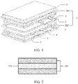
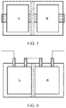
- the electrochemical apparatus includes a barrier 1, where the barrier 1 is hermetically connected to an outer package 3, standalone chambers are formed at two sides of the barrier 1, each chamber encapsulates an electrode assembly 2 and an electrolyte, and adjacent electrode assemblies 2 are connected in series by tabs, which may be that a positive tab 4 of an electrode assembly 201 and a negative tab 5 of an electrode assembly 202 are connected in series, or that a negative tab 5 of an electrode assembly 201 and a negative tab 4 of an electrode assembly 202 are connected in series.
- the barrier 1 includes an ion insulating layer for ion insulation.
- the chamber is a sealed chamber.
- water permeability of the barrier is less than or equal to 10 -3 g/(day ⁇ m 2 ⁇ Pa)/3 mm. Greater water permeability of the barrier allows water vapor in the environment to more easily penetrate into the battery through the barrier, resulting in an increase in water contained in a non-aqueous electrolyte, an increase in thickness of the battery, and a decrease in service life of the battery.
- Sealing thickness T (in mm) and sealing width W (in mm) of a seal between the barrier and the outer package satisfy 0.01 ⁇ T/W ⁇ 0.05.
- the ratio T/W falling within the foregoing range can ensure that the battery is well sealed, prolonging the service life of the battery.
- T/W is too small, the sealing thickness may be insufficient so that a sealing effect is poor, making the battery less stable in the environment. For example, water vapor in the environment can easily penetrate into the battery, resulting in increased water contained in the battery, electrolyte decomposition, and shortened service life of the battery.
- the sealing width W may be too small and a sealing effect is also poor, making the battery less stable in the environment.
- the sealing thickness and sealing width are not particularly limited provided that the purpose of the present invention can be achieved.
- the sealing width preferably ranges from 1 mm to 7 mm.
- the sealing thickness is thickness of a sealing material in a sealing zone; and the sealing width is width of the sealing material in the sealing zone.
- the sealing zone is a zone at which the barrier and the outer package are sealed together. During the sealing, a polymer material in the inner layer of the outer package and a polymer material in the barrier are sealed together by hot pressure to form a sealing zone.
- the sealing thickness includes thickness of the polymer material in the barrier and the polymer material in the inner layer of the outer package that are fused.
- the sealing width is width of the sealing zone formed after the polymer material in the barrier is hot pressed with the polymer material of the inner layer of the outer package.
- a direction of the sealing thickness is a stacking direction of the outer package and the barrier, and a direction of the sealing width is a distance between two sealing edges.
- the barrier is hermetically connected to the outer package with standalone chambers formed at two sides of the barrier, and the electrode assemblies and electrolytes at the two sides of the barrier are completely separated, which guarantees normal operation of the electrode assemblies at the two sides.
- good sealing is conducive to improving safety and environmental stability of the electrochemical apparatus.
- the barrier has the characteristic of ion insulation. Therefore, high-voltage decomposition of the electrolyte and short circuit in the electrode assembly can be avoided.
- the electrode assemblies at the two sides of the barrier are connected in series, so that not only high voltage output of the electrochemical apparatus is achieved, but also total heat production by battery cells and a temperature rise during use are reduced.
- limiting the water permeability of the barrier to the foregoing range can more effectively avoid safety problems caused when the electrochemical apparatus is working in a high-humidity environment; and limiting the ratio of the sealing thickness T to the sealing width W to the foregoing range can more effectively achieve sealing of the electrochemical apparatus, thereby further improving the safety of the electrochemical apparatus.
- the structure of the ion insulating layer is not particularly limited, provided that the purpose of the present invention can be achieved.
- the ion insulating layer may have a single-layer structure or a multi-layer composite structure.
- the ion insulating layer is made of at least one of a polymer material, a metal material, a carbon material, or a composite material thereof.
- the polymer material is not particularly limited, and any material known to those skilled in the art may be used, provided that the purpose of the present invention can be achieved.
- the polymer material may include at least one of polyethylene terephthalate, polybutylene terephthalate, polyethylene naphthalate, polyether ether ketone, polyimide, polyamide, polyethylene glycol, polyamide imide amine, polycarbonate, cyclic polyolefin, polyphenylene sulfide, polyvinyl acetate, polytetrafluoroethylene, polymethylene naphthalene, polyvinylidene fluoride, polyethylene naphthalate, polypropylene carbonate ester, poly(vinylidene fluoride-hexafluoropropylene), poly(vinylidene fluoride-co-chlorotrifluoroethylene), silicone, vinylon, polypropylene, anhydride modified polypropylene, polyethylene, ethylene-acetic acid ethylene copolymer
- the metal material is not particularly limited, and any material known to those skilled in the art may be used, provided that the purpose of the present invention can be achieved.
- the metal material may include at least one of Ni, Ti, Cu, Ag, Au, Pt, Fe, Co, Cr, W, Mo, Al, Mg, K, Na, Ca, Sr, Ba, Si, Ge, Sb, Pb, In, Zn, stainless steel, and compositions or alloys thereof.
- a metal material with better oxidation-reduction resistance under the environment of a lithium-ion battery may be selected.
- the carbon material includes at least one of carbon felt, carbon film, carbon black, acetylene black, fullerene, conductive graphite film, or graphene film.
- the ion insulating layer preferably uses a polymer material. Because the polymer material has low density, a weight of inactive substance can be reduced, thereby increasing mass energy density of the electrode assembly.
- the ion insulating layer using a polymer material can reduce a probability of generating debris under mechanical abuse (nail penetration, impact, extrusion, and the like), and provide a better wrapping effect on a mechanically damaged surface. Therefore, safety boundary under the condition of the above-mentioned mechanical abuse can be improved, and a pass rate of safety test can be increased.
- the ion insulating layer is preferably made of a metal material, which has strong isolation reliability, better toughness and compactness than polymer materials, and thinner processing thickness.
- the ion insulating layer preferably uses a carbon material film, a product with the ion insulating layer has excellent safety performance, especially excellent high-temperature reliability, and has the function of separating battery cells at two sides of the ion insulating layer when a main body of a battery cell is damaged.
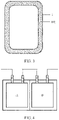
- the barrier further includes an encapsulating layer 102, and the encapsulating layer 102 may be disposed at two sides of the ion insulating layer 101, as shown in FIG. 2 .
- the encapsulating layer 102 is used for hermetically connect the ion insulating layer 101 and the outer package. In other embodiments, the encapsulating layer 102 may alternatively be disposed on the outer package.
- the encapsulating layer is disposed at a circumferential edge around a surface of the ion insulating layer or on the entire surface of the ion insulating layer.
- width of the encapsulating layer is not particularly limited, provided that it is greater than the sealing width so as to ensure the required sealing width.
- the encapsulating layer 102 is disposed at the circumferential edge around the surface of the ion insulating layer 101, which minimizes a coating amount and a proportion of the encapsulating layer, reduces a proportion of inactive substance, and thus can increase the energy density of the battery cell.
- the encapsulating layer being disposed on the entire surface of the ion insulating layer can effectively reduce the water permeability of the barrier, and when the electrochemical apparatus is working in a high air humidity environment, can more effectively avoid short circuit and even safety failure of the electrochemical apparatus due to water absorption of the barrier.
- the encapsulating layer is disposed at the circumferential edge around the surface of the ion insulating layer, the ion insulating layer is made of a conductive material, and at least one of the electrode assemblies at the two sides of the barrier has a separator present on the outermost side adjacent to the barrier.
- the encapsulating layer is disposed at the circumferential edge around the surface of the ion insulating layer, the ion insulating layer is made of an insulating material, and the electrode assemblies at the two sides of the barrier may each have one of a separator, a positive electrode current collector, a negative electrode current collector, a positive electrode active material, and a negative electrode active material present on the outermost side adjacent to the barrier.
- the encapsulating layer is disposed on the entire surface of the ion insulating layer, the ion insulating layer is made of an insulating material, and the electrode assemblies at the two sides of the barrier may each have one of a separator, a positive electrode current collector, a negative electrode current collector, a positive electrode active material, and a negative electrode active material present on the outermost side adjacent to the barrier.
- a material of the encapsulating layer is not particularly limited, and materials known to those skilled in the art can be used, provided that the purpose of the present invention can be achieved.
- the material of the encapsulating layer includes at least one of polypropylene, acid anhydride modified polypropylene, polyethylene, ethylene-vinyl acetate copolymer, ethylene-ethyl acrylate copolymer, ethylene-acrylic acid copolymer, ethylene-vinyl alcohol copolymer, polyvinyl chloride, polystyrene, polyether nitrile, polyurethane, polyamide, polyester, and amorphous ⁇ -olefin copolymer and its derivatives.
- the encapsulating layer of the present invention covers the entire surface of the ion insulating layer
- the encapsulating layer also has the function of ion insulation.
- the barrier is divided into the ion insulating layer and the encapsulating layer, which does not mean that the encapsulating layer has no ion insulating properties.
- the ion insulating layer and the encapsulating layer play a role of ion insulation together.
- thickness of the barrier ranges from 6 ⁇ m to 100 ⁇ m.
- the barrier not only has the characteristic of ion insulation, but should also have some mechanical strength. Therefore, if the barrier is too thin so that the mechanical strength is poor, it is easy to cause damage and affect the performance and even the safety of the electrochemical apparatus. If the barrier is too thick, conduction of electrons is affected and the energy density of the electrochemical apparatus is reduced, which limits the performance of the electrochemical apparatus.
- the thickness of the barrier is thickness of the ion insulating layer itself.
- the thickness of the barrier is a sum of thickness of the ion insulation layer and thicknesses of the encapsulating layers at the two sides of the ion insulation layer.
- the thickness of the encapsulating layers at the two sides of the ion insulating layer may be the same or different, provided that the purpose of the present invention can be achieved.
- the thicknesses of the encapsulating layers at the two sides of the ion insulating layer are the same.
- the electrochemical apparatus has at least one of the following characteristics:
- the barrier is hermetically connected to the outer package, to be specific, the encapsulating layer of the barrier is hermetically connected to an inner layer of the outer package, so that the standalone sealed chambers are formed in the electrochemical apparatus, and ionic insulation is achieved between a plurality of electrode assemblies of a liquid electrolyte battery with series connection inside, avoiding potential safety hazards such as internal short circuit or high-voltage decomposition of the electrolyte, and improving the safety performance of the electrochemical apparatus. Therefore, limiting the melting point of the encapsulating material to the foregoing temperature is more conducive to achieving a hermetical connection between the barrier and the outer package.
- a structure of the electrode assembly includes a winding structure or a laminated structure.
- a structure of the electrode assembly is a winding structure, and the electrode assembly includes single tab or multiple tabs.
- the electrode assembly including single tab means one positive tab and one negative tab are respectively led out from a positive electrode plate and a negative electrode plate.
- the electrode assembly including multiple tabs means one positive tab and one negative tab may be led out from each circle of positive electrode plate and negative electrode plate respectively, or one positive tab and one negative tab may be led out from each two or more circles of positive electrode plate and negative electrode plate respectively, so that the electrode assembly of the winding structure finally includes a plurality of sets of positive tabs and negative tabs which are then connected to tab leads by welding.
- the structure of the electrode assembly is a laminated structure, and the electrode assembly includes multiple tabs, meaning one positive tab and one negative tab may be led out from each layer of positive electrode plate and negative electrode plate respectively, so that the electrode assembly of the laminated structure finally includes a plurality of sets of positive tabs and negative tabs which are then connected to tab leads by welding.
- the welding method is not particularly limited, provided that the purpose of this application can be achieved.
- the welding may be laser welding, ultrasonic welding, or resistance welding.
- the electrode assembly in this application may be an electrode assembly including a positive electrode plate, a negative electrode plate, and a separator, and the foregoing electrode assembly is used as an example for description. Those skilled in the art should understand that the following description is merely for example purposes and does not limit the protection scope of this application.
- the positive electrode plate is not particularly limited, provided that the purpose of this application can be achieved.
- the positive electrode plate typically includes a positive electrode current collector and a positive electrode active material.
- the positive electrode current collector is not particularly limited, and may be any positive electrode current collector known in the art, such as copper foil, aluminum foil, aluminum alloy foil, or a composite current collector.
- the positive electrode active material is not particularly limited, and may be any positive electrode active material in the prior art.
- the positive electrode active material includes at least one of lithium nickel cobalt manganate, lithium nickel cobalt aluminate, lithium iron phosphate, lithium cobalt oxide, and lithium manganate, or lithium iron manganese phosphate.
- thicknesses of the positive electrode current collector and that of the positive electrode active material are not particularly limited, provided that the purpose of this application can be achieved.
- the thickness of the positive electrode current collector ranges from 8 ⁇ m to 12 ⁇ m
- the thickness of the positive electrode active material ranges from 30 ⁇ m to 120 ⁇ m.
- the positive electrode plate may further include a conductive layer.
- the conductive layer is sandwiched between the positive electrode current collector and a positive electrode active material layer.
- Composition of the conductive layer is not particularly limited, and the conductive layer may be a conductive layer commonly used in the art.
- the conductive layer includes a conductive agent and a binder.
- the negative electrode plate is not particularly limited, provided that the purpose of this application can be achieved.
- the negative electrode plate typically includes a negative electrode current collector and a negative electrode active material.
- the negative electrode current collector is not particularly limited, and any negative electrode current collector known in the art may be used, for example, copper foil, aluminum foil, aluminum alloy foil, or a composite current collector.
- the negative electrode active material is not particularly limited, and any negative electrode active material known in the art may be used.
- the negative electrode active material may include at least one of artificial graphite, natural graphite, mesophase carbon microsphere, silicon, silicon carbon, silicon oxygen compound, soft carbon, hard carbon, lithium titanateor niobium titanate.
- thicknesses of the negative electrode current collector and that of the negative electrode active material are not particularly limited, provided that the purpose of this application can be achieved.
- the thickness of the negative electrode current collector ranges from 6 ⁇ m to 10 ⁇ m
- the thickness of the negative electrode active material ranges from 30 ⁇ m to 120 ⁇ m.
- the negative electrode plate may further include a conductive layer.
- the conductive layer is sandwiched between the negative electrode current collector and a negative electrode active material layer.
- Composition of the conductive layer is not particularly limited, and the conductive layer may be a conductive layer commonly used in the art.
- the conductive layer includes a conductive agent and a binder.
- the conductive agent is not particularly limited, and any conductive agent known in the art can be used, provided that the purpose of this application can be achieved.
- the conductive agent may include at least one of conductive carbon black (Super P), carbon nanotubes (CNTs), carbon nanofibers, graphene, or the like.
- the binder is not particularly limited, and any binder known in the art can be used, provided that the purpose of this application can be achieved.
- the binder may include at least one of styrene butadiene rubber (SBR), polyvinyl alcohol (PVA), polytetrafluoroethylene ethylene (PTFE), sodium carboxymethyl cellulose (CMC-Na), or the like.
- the separator in this application is not particularly limited, provided that the purpose of this application can be achieved.
- thickness of the separator may range from 5 ⁇ m to 15 ⁇ m
- the separator may include a polymer or an inorganic substance formed by a material stable to the electrolyte of this application.
- the separator may include a substrate layer and a surface treatment layer.
- the substrate layer may be a non-woven fabric, film, or composite film of a porous structure.
- the substrate layer may be made of at least one of polyethylene, polypropylene, polyethylene terephthalate, and polyimide.
- a polypropylene porous membrane, a polyethylene porous membrane, polypropylene nonwoven fabric, polyethylene nonwoven fabric, or polypropylene-polyethylene-polypropylene porous composite membrane can be used.
- a surface treatment layer is provided on at least one surface of the substrate layer, and the surface treatment layer may be a polymer layer or an inorganic substance layer, or a layer formed by a mixture of a polymer and an inorganic substance.
- the inorganic layer includes inorganic particles and a binder.
- the inorganic particles are not particularly limited, and may include, for example, at least one of aluminum oxide, silicon oxide, magnesium oxide, titanium oxide, hafnium oxide, tin oxide, ceria oxide, nickel oxide, zinc oxide, calcium oxide, zirconium oxide, yttrium oxide, silicon carbide, boehmite, aluminum hydroxide, magnesium hydroxide, calcium hydroxide, or barium sulfate.
- the binder is not particularly limited, and may be selected from, for example, a combination of one or more of polyvinylidene fluoride, vinylidene fluoride-hexafluoropropylene copolymer, polyamide, polyacrylonitrile, polyacrylate, polyacrylic acid, polyacrylate, polyvinylpyrrolidone, polyvinyl ether, polymethyl methacrylate, polytetrafluoroethylene, and polyhexafluoropropylene.
- the polymer layer includes a polymer, and a material of the polymer includes at least one of polyamide, polyacrylonitrile, acrylate polymer, polyacrylic acid, polyacrylate, polyvinylpyrrolidone, polyvinyl ether, polyvinylidene fluoride, or poly(vinylidene fluoride-hexafluoropropylene).
- the tab in this application refers to a metal conductor led out from a positive electrode plate or a negative electrode plate, which is configured to be connected to other parts of the electrochemical apparatus in series or parallel.
- the positive tab is led out from the positive electrode plate, and the negative tab is led out from the negative electrode plate.
- the electrolyte mentioned in this application may contain a lithium salt and a non-aqueous solvent.
- the lithium salt is not particularly limited, and any lithium salt known in the art can be used, provided that the purpose of this application can be achieved.
- the lithium salt may include at least one of LiPF 6 , LiBF 4 , LiAsF 6 , LiClO 4 , LiB(C 6 H 5 ) 4 , LiCH 3 SO 3 , LiCF 3 SO 3 , LiN(SO 2 CF 3 ) 2 , LiC(SO 2 CF 3 ) 3 , or LiPO 2 F 2 .
- LiPF 6 can be selected as the lithium salt.
- the non-aqueous solvent is not particularly limited, provided that the purpose of this application can be achieved.
- the non-aqueous solvent may include at least one of a carbonate compound, a carboxylate compound, an ether compound, a nitrile compound, or other organic solvents.
- the carbonate compound may include at least one of diethyl carbonate (DEC), dimethyl carbonate (DMC), dipropyl carbonate (DPC), methyl propyl carbonate (MPC), ethyl propyl carbonate (EPC), methyl ethyl carbonate (MEC), ethylene carbonate (EC), propylene carbonate (PC), butylene carbonate (BC), vinyl ethylene carbonate (VEC), fluoroethylene carbonate (FEC), 1,2-difluoroethylene carbonate, 1,1-difluoroethylene carbonate, 1,1,2-trifluoroethylene carbonate, 1,1,2,2-tetrafluoroethylene carbonate, 1-fluoro-2-methyl ethylene carbonate, 1-fluoro-1-methylethylene carbonate, 1,2-difluoro-1-methylethylene carbonate, 1,1,2-trifluoro-2-methylethylene carbonate, or trifluoromethylethylene carbonate.
- DEC diethyl carbonate
- DMC dimethyl carbonate
- DPC dipropyl carbon
- the outer package is not particularly limited, provided that the purpose of this application can be achieved.
- the outer package may include an inner layer and an outer layer, and the inner layer is hermetically connected to the barrier. Therefore, a material of the inner layer may include a polymer material to achieve a good sealing effect; and the combination of the inner layer and the outer layer can effectively protect the internal structure of the electrochemical apparatus.
- the material of the inner layer in this application is not particularly limited, provided that the purpose of the application can be achieved.
- the material of the inner layer includes at least one of polypropylene, polyester, p-hydroxybenzaldehyde, polyamide, polyphenylene ether, polyurethane, or the like.
- a material of the outer layer is not particularly limited, provided that the purpose of the application can be achieved.
- the material of the outer layer includes at least one of aluminum foil, aluminum oxide layer, silicon nitride layer, Ni, Cu, Ag, Al.
- thickness of the outer package is not particularly limited, provided that the purpose of this application can be achieved.
- the thickness of the outer package ranges from 60 ⁇ m to 200 ⁇ m, and the outer package of such thickness can effectively protect the internal structure of the electrochemical apparatus.
- the hermetic connection method between the barrier and the outer package is not particularly limited, provided that the purpose of this application can be achieved.
- the hermetic method may use hot pressing.
- the hot pressing condition is not particularly limited, provided that the purpose of the application can be achieved.
- a hot pressing temperature ranges from 150°C to 220°C
- a hot pressing pressure ranges from 0.1 MPa to 0.6 MPa.
- the electronic apparatus in this application is not particularly limited, and may be any known electronic apparatus in the prior art.
- the electronic apparatus may include but is not limited to a notebook computer, a pen-input computer, a mobile computer, an electronic book player, a portable telephone, a portable fax machine, a portable copier, a portable printer, a stereo headset, a video recorder, a liquid crystal television, a portable cleaner, a portable CD player, a mini-disc, a transceiver, an electronic notepad, a calculator, a memory card, a portable recorder, a radio, a standby power source, a motor, an automobile, a motorcycle, a power-assisted bicycle, a bicycle, a lighting appliance, a toy, a game console, a clock, an electric tool, a flash lamp, a camera, a large household battery, a lithium-ion capacitor, or the like.
- a method for preparing the electrochemical apparatus of this application is not particularly limited, and any method known in the art can be used.
- this application may use the following preparation method:
- the electrochemical apparatus provided in this application may include two electrode assemblies, or may include three or more electrode assemblies.
- preparation method of an electrochemical apparatus containing two electrode assemblies or three or more electrode assemblies refer to the preparation method of the foregoing electrochemical apparatus.
- a film with a specific thickness (for example, 60 ⁇ m) was prepared.
- the film was placed on a clamping mechanism, and edges of the film were compressed tight by rubber with a high pressure.
- a constant temperature and humidity environment was created at one side A of the apparatus, and a probe of a water vapor mass spectrometer was disposed at the other side B, gas exchange between the two sides could be completed through only the film.
- the film was first fixed, and the chamber B was evacuated to exhaust internal water vapor.
- the mass spectrometer was then turned on which continuously received the water vapor permeated from the chamber A and converted the water vapor into electrical signals for output.
- the foregoing test lasted for 24 hours or longer to obtain a total water permeation m during this period.
- the total permeation m was divided by time, water vapor partial pressure, permeation area, and film thickness to obtain the water vapor permeability in g/(day M 2 ⁇ Pa)/3 mm.
- the electrochemical apparatus was left standing for 30 minutes at a room temperature, charged to a voltage of 4.4 V (rated voltage) at a constant current charging rate of 0.05C, and then the electrochemical apparatus was discharged to 3.0 V at a rate of 0.05C.
- the foregoing charging/discharging steps were repeated for three cycles to complete the formation of the electrochemical apparatus to be tested.
- the electrochemical apparatus was charged to a voltage of 4.4 V at a constant current rate of 0.1C, then discharged 3.0 V at a discharge rate of 0.1C.
- the battery cell was charged to 4.45 V at a constant current of 1.0C, and then charged at a constant voltage until the current dropped to 0.05C. Charging was stopped. The battery cell was left standing for 1 hour and then was removed. An initial thickness T1 of the battery cell was measured. The battery cell was placed in an environment of 65°C_90%RH for seven days, its thickness T2 was tested and compared with its initial thickness in storage to find its thickness growth, where the growth rate was (T2-T1)/T1 ⁇ 100%.
- the electrochemical apparatus to be tested was charged to a voltage of 4.45 V (rated voltage in Comparative Example 1) or 8.90 V (in other Comparative Examples and all Examples) at a constant current rate of 0.05C, and then charged to a current of 0.025C (cutoff current) at a constant voltage, to make the battery reach a fully charged state.
- the appearance of the electrochemical apparatus before the test was recorded.
- Nail penetration test was performed on the electrochemical apparatus in an environment of 25 ⁇ 3°C.
- the diameter of the steel nail was 4 mm, the penetration speed was 30 mm/s, and the nail penetration positions were 15 mm from an edge of the electrode assembly at the positive tab and 15 mm from an edge of the electrode assembly at the negative tab.
- the test was carried out for 3.5 minutes or the temperature of the surface of the electrode assembly dropped to 50°C, the test was stopped. With 10 battery cells as one group, the battery status was observed during the test. The pass criterion was that the battery did not burn or explode.
- the test temperature was 25°C.
- a temperature probe was attached to the center of the surface of the batter cell, the temperature of the main body of the battery cell was monitored, and foam was wrapped on the surface of the battery cell to weaken the heat exchange between the battery cell and the contacts.
- the test process was as follows: The battery cell was discharged to 6 V (6 V for a battery cell with series connection) or 3 V (3 V for a single battery cell in Comparative Examples, with the same applying hereinafter) at a constant current of 0.2C, then charged to 8.4 V or 4.2 V at a constant current of 0.5C, charged to 8.9 V or 4.45 V at 0.2C, and left standing for 120 min until the temperature at the center of the battery cell dropped to 25°C at the room temperature. The same power 15 W was used for discharge, and the temperature rise of the main body of the battery cell was monitored during the discharge process.
- the ion insulating layer was Ti metal foil with a thickness of 10 ⁇ m, and the rest were the same as those in Example 1.
- the ion insulating layer was SUS metal foil with a thickness of 10 ⁇ m, and the rest were the same as those in Example 1.
- the ion insulating layer was PI metal foil with a thickness of 10 ⁇ m, and the rest were the same as those in Example 1.
- the thickness of the barrier was 6 ⁇ m
- the ion insulating layer was Ti metal foil with a thickness of 6 ⁇ m
- provided at surrounding edges of the ion insulating layer were an encapsulating layer with a thickness of 10 ⁇ m and a width of 2 mm
- the encapsulating layer was made of PP and had a melting point of 140°C, and the rest were the same as those in Example 1.
- the thickness of the barrier was 100 ⁇ m
- the thickness of the ion insulating layer was 80 ⁇ m
- the thickness of the encapsulating layer at each of two sides was 10 ⁇ m
- the rest were the same as those in Example 1.
- the thickness of the barrier was 15 ⁇ m
- the thickness of the ion insulating layer was 15 ⁇ m
- provided at surrounding edges of the ion insulating layer were an encapsulating layer with a thickness of 10 ⁇ m and a width of 2 mm
- the encapsulating layer was made of PP and had a melting point of 140°C, and the rest were the same as those in Example 1.
- the ion insulating layer was Ti metal foil with a thickness of 10 ⁇ m, a PP material with a melting point of 140° C and a thickness of 10 ⁇ m was selected as the encapsulating layer at each of the two sides, and the rest were the same as those in Example 8.
- the ion insulating layer was Ti metal foil with a thickness of 10 ⁇ m, a PP material with a melting point of 140° C and a thickness of 10 ⁇ m was selected as the encapsulating layer at each of the two sides, and the rest were the same as those in Example 9.
- Example 1 An acid anhydride modified PP with a melting point of 130°C was selected as the encapsulating layer, and the water vapor permeability of the barrier was 8 ⁇ 10 -5 g/(day ⁇ m 2 ⁇ Pa)/3 mm, and the rest were the same as those in Example 1.
- the thickness of the sealing zone was 0.1 mm, the width of the sealing zone was 2 mm, and the rest were the same as those in Example 1.
- the thickness of the sealing zone was 0.05 mm, the width of the sealing zone was 2 mm, and the rest were the same as those in Example 1.
- the ion insulating layer was a carbon film, the thickness of the ion insulating layer was 20 ⁇ m, provided at surrounding edges of the ion insulating layer were an encapsulating layer with a thickness of 10 ⁇ m and a width of 2 mm, the encapsulating layer was made of PP and had a melting point of 140°C, and the rest were the same as those in Example 1.
- the ion insulating layer was a graphene film, the thickness of the ion insulating layer was 20 ⁇ m, provided at surrounding edges of the ion insulating layer were an encapsulating layer with a thickness of 10 ⁇ m and a width of 2 mm, the encapsulating layer was made of PP and had a melting point of 140°C, and the rest were the same as those in Example 1.
- Polyphenyl ether with a melting point of 120°C was selected as the encapsulating layer, and the water vapor permeability of the barrier was 2.5 ⁇ 10 -4 g/(day ⁇ m 2 ⁇ Pa)/3 mm, and the rest were the same as those in Example 1.
- the output voltage of the battery was increased through series connection according to this application, high energy density and high nail penetration pass rate were maintained, and the self-discharge rate was low.
- the barrier of this application With the barrier of this application, the stability in a humid environment was significantly improved, and the battery of this application maintained a low thickness growth rate, indicating that the battery of the embodiments of this application can prevent water vapor from penetrating into the battery and prolong the service life of the battery.
- the water vapor permeability of the barrier is too high, for example, exceeds the range defined in this application, the thickness growth rate of the battery increases significantly, indicating that the water resistance of the battery is reduced, which may affect the service life.
- the sealing thickness to the sealing width is lower than the lower limit of the range defined in this application, for example, the sealing width of the battery is excessively large, although the sealing intensity is increased, the energy density of the battery will be significantly reduced, and when the sealing thickness of the battery is excessively small, the sealing intensity is significantly reduced.
- the ratio of the sealing thickness to the sealing width is higher than the upper limit of the range defined in this application, for example, when the sealing thickness is excessively large, the growth rate of the battery increases significantly. Without being limited to any theory, the applicant believes that excessive sealing thickness may cause water vapor to penetrate into the battery from the sealing zone, thereby reducing the water resistance of the battery.
Landscapes
- Chemical & Material Sciences (AREA)
- Chemical Kinetics & Catalysis (AREA)
- Electrochemistry (AREA)
- General Chemical & Material Sciences (AREA)
- Engineering & Computer Science (AREA)
- Manufacturing & Machinery (AREA)
- Materials Engineering (AREA)
- Inorganic Chemistry (AREA)
- Composite Materials (AREA)
- Secondary Cells (AREA)
- Sealing Battery Cases Or Jackets (AREA)
- Electric Double-Layer Capacitors Or The Like (AREA)
- Cell Separators (AREA)
- Connection Of Batteries Or Terminals (AREA)
Abstract
Description
- The present invention relates to the electrochemistry field, and in particular, to an electrochemical apparatus and an electronic apparatus using such electrochemical apparatus.
- In existing lithium-ion battery systems, the open circuit voltage of a battery hardly exceeds 5 V due to factors such as a limited voltage difference between a positive electrode material and a negative electrode material and a limited capability of an electrolytic solution in resisting oxidation and reduction.. However, in the actual use of batteries, there are many scenarios in which a voltage exceeding 5 V needs to be used, for example, electric vehicles (EV), power tools (PT), and energy storage systems (ESS). Even in the mobile phone market, in order to meet such needs as fast charging, it is also necessary to increase the open-circuit voltage of cells. Currently, a plurality of lithium-ion batteries are generally connected in series to increase the output voltage, but there are many problems with the plurality of lithium-ion batteries connected in series. For example, overall energy density (ED) of the lithium-ion batteries is low due to the capacity difference between individual lithium-ion batteries; wires for series connection and contact resistance introduce additional electronic resistance, which causes heating to waste energy and affects battery life; and a higher voltage requires more lithium-ion batteries, which increases the difficulty of battery management. In order to resolve the above problems, the concept of high output voltage battery is proposed, which realizes high-voltage output of a single lithium-ion battery by means of series connection inside the battery, thereby reducing the total heat production of the battery and reducing the temperature rise during use.
- In the prior art, the technique of the series-connected batteries is to connect two batteries in series directly in the same packaging bag, without ionic insulation between the two series-connected electrode assemblies. If the battery voltage rises so that the electrolyte is decomposed under high voltage conditions, the battery will fail. In addition, an internal short circuit will occur between the two electrode assemblies due to the voltage difference of electrode plates, which will also cause the battery to fail. For the above reasons, the current solution proposed is only applicable to solid electrolyte batteries. However, mainstream lithium batteries are liquid electrolyte batteries. Therefore, the foregoing solution is hard to popularize.
- The objective of this application is to provide an electrochemical apparatus, which can not only achieve high voltage output, but also reduce a temperature rise of the electrochemical apparatus.
- A first aspect of this application provides an electrochemical apparatus, including a barrier, where the barrier is hermetically connected to an outer package, standalone chambers are formed at two sides of the barrier respectively, each chamber encapsulates an electrode assembly and an electrolyte, electrode assemblies in adjacent chambers are connected in series by tabs, and the barrier includes an ion insulating layer; water permeability of the barrier is less than or equal to 10-3 g/(day·m2·Pa)/3 mm; and sealing thickness T and sealing width W of a seal between the barrier and the outer package satisfy 0.01≤T/W≤0.05.
- In an embodiment of this application, the sealing width W ranges from 1 mm to 7 mm.
- In an embodiment of this application, the chamber is a sealed chamber.
- In an embodiment of this application, the ion insulating layer is made of at least one of a polymer material, a metal material, and a carbon material.
- In an embodiment of this application, the polymer material includes at least one of polyethylene terephthalate, polybutylene terephthalate, polyethylene naphthalate, polyether ether ketone, polyimide, polyamide, polyethylene glycol, polyamide imide amine, polycarbonate, cyclic polyolefin, polyphenylene sulfide, polyvinyl acetate, polytetrafluoroethylene, polymethylene naphthalene, polyvinylidene fluoride, polyethylene naphthalate, polypropylene carbonate ester, poly(vinylidene fluoride-hexafluoropropylene), poly(vinylidene fluoride-co-chlorotrifluoroethylene), silicone, vinylon, polypropylene, anhydride modified polypropylene, polyethylene, ethylene-acetic acid ethylene copolymer, ethylene-ethyl acrylate copolymer, ethylene-acrylic acid copolymer, ethylene-vinyl alcohol copolymer, polyvinyl chloride, polystyrene, polyether nitrile, polyurethane, polyphenylene ether, polyester, polysulfone, and non-crystalline α-olefin copolymer and its derivatives. The metal material includes at least one of Ni, Ti, Cu, Ag, Au, Pt, Fe, Co, Cr, W, Mo, Al, Mg, K, Na, Ca, Sr, Ba, Si, Ge, Sb, Pb, In, Zn, stainless steel, and compositions or alloys thereof. The carbon material includes at least one of carbon felt, carbon film, carbon black, acetylene black, fullerene, conductive graphite film, or graphene film.
- In an embodiment of this application, the barrier further includes an encapsulating layer, where the encapsulating layer is disposed at a circumferential edge around a surface of the ion insulating layer or on the entire surface of the ion insulating layer, and a material of the encapsulating layer has a melting point ranging from 120°C to 160°C.
- In an embodiment of this application, the encapsulating layer includes at least one of polypropylene, acid anhydride modified polypropylene, polyethylene, ethylene-vinyl acetate copolymer, ethylene-ethyl acrylate copolymer, ethylene-acrylic acid copolymer, ethylene-vinyl alcohol copolymer, polyvinyl chloride, polystyrene, polyether nitrile, polyurethane, polyamide, polyester, and amorphous α-olefin copolymer and its derivatives.
- In an embodiment of this application, thickness of the barrier ranges from 6 µm to 100 µm.
- In an embodiment of this application, the ion insulating layer is a single-layer or multi-layer structure.
- In an embodiment of this application, the electrochemical apparatus has at least one of the following characteristics:
- (a) the water permeability of the barrier is less than or equal to 10-4 g/(day·m2·Pa)/3 mm;
- (b) thickness of the barrier ranges from 10 µm to 40 µm; and
- (c) a material of the ion insulating layer has a melting point higher than or equal to 165°C.
- In an embodiment of this application, a structure of the electrode assembly includes a winding structure or a laminated structure.
- A second aspect of this application provides an electronic apparatus. The electronic apparatus includes the electrochemical apparatus according to the first aspect of this application.
- In the electrochemical apparatus provided in this application, the barrier is hermetically connected to the outer package with standalone chambers formed at two sides of the barrier, and the electrode assemblies and electrolytes at the two sides of the barrier are completely separated, which guarantees normal operation of the electrode assemblies at the two sides. In addition, good sealing is conducive to improving safety of the electrochemical apparatus. Furthermore, the barrier has the characteristic of ion insulation. Therefore, high-voltage decomposition of the electrolyte and short circuit in the electrode assembly can be avoided. The electrode assemblies at the two sides of the barrier are connected in series, so that not only high voltage output of the electrochemical apparatus is achieved, but also total heat production by battery cells and a temperature rise during use are reduced. The water permeability of the barrier is limited to be less than or equal to 10-3 g/(day·m2·Pa)/3 mm, and the sealing thickness T and sealing width W of the seal between the barrier and the outer package are limited to satisfy 0.01≤T/W≤0.05, so that water resistance and environmental stability of a battery can be improved.
- To describe the technical solutions in the embodiments of the present invention and in the prior art more clearly, the following briefly describes the accompanying drawings required for describing the embodiments and the prior art. Apparently, the accompanying drawings in the following description show merely some embodiments of the present invention, and a person of ordinary skill in the art may derive other embodiments from these accompanying drawings without creative efforts.
-
FIG. 1 is a schematic structural diagram of an electrochemical apparatus according to an embodiment of this application; -
FIG. 2 is a schematic diagram of a cross-sectional structure of a barrier according to an embodiment of this application; -
FIG. 3 is a schematic structural diagram of a barrier according to an embodiment of this application; -
FIG. 4 is a schematic structural diagram of an electrochemical apparatus in Comparative Example 1; -
FIG. 5 is a schematic structural diagram of an electrochemical apparatus in Comparative Example 2; and -
FIG. 6 is a schematic structural diagram of an electrochemical apparatus in Comparative Example 3. - To make the objectives, technical solutions, and advantages of the present invention more comprehensible, the following describes the present invention in detail with reference to embodiments and accompanying drawings. Apparently, the described embodiments are merely some but not all of the embodiments of the present invention.
- The electrochemical apparatus of this application may be any electrochemical apparatus well known to those skilled in the art, such as a lithium-ion battery, a sodium-ion battery, a magnesium-ion battery, and a super capacitor. The following uses a lithium-ion battery as an example for description. Those skilled in the art should understand that the following description is merely for example purposes and does not limit the protection scope of this application.
- This application provides an electrochemical apparatus. A typical implementation is shown in
FIG. 1 . The electrochemical apparatus includes abarrier 1, where thebarrier 1 is hermetically connected to an outer package 3, standalone chambers are formed at two sides of thebarrier 1, each chamber encapsulates anelectrode assembly 2 and an electrolyte, andadjacent electrode assemblies 2 are connected in series by tabs, which may be that a positive tab 4 of anelectrode assembly 201 and anegative tab 5 of anelectrode assembly 202 are connected in series, or that anegative tab 5 of anelectrode assembly 201 and a negative tab 4 of anelectrode assembly 202 are connected in series. Thebarrier 1 includes an ion insulating layer for ion insulation. The chamber is a sealed chamber. - In this application, water permeability of the barrier is less than or equal to 10-3 g/(day·m2·Pa)/3 mm. Greater water permeability of the barrier allows water vapor in the environment to more easily penetrate into the battery through the barrier, resulting in an increase in water contained in a non-aqueous electrolyte, an increase in thickness of the battery, and a decrease in service life of the battery.
- Sealing thickness T (in mm) and sealing width W (in mm) of a seal between the barrier and the outer package satisfy 0.01≤T/W≤0.05.The ratio T/W falling within the foregoing range can ensure that the battery is well sealed, prolonging the service life of the battery. When T/W is too small, the sealing thickness may be insufficient so that a sealing effect is poor, making the battery less stable in the environment. For example, water vapor in the environment can easily penetrate into the battery, resulting in increased water contained in the battery, electrolyte decomposition, and shortened service life of the battery. When the ratio T/W is too large, the sealing width W may be too small and a sealing effect is also poor, making the battery less stable in the environment. For example, the water vapor in the environment can easily penetrate into the battery, resulting in increased water contained in the battery, electrolyte decomposition, and other problems, thereby reducing the service life of the battery. In this application, the sealing thickness and sealing width are not particularly limited provided that the purpose of the present invention can be achieved. For example, the sealing width preferably ranges from 1 mm to 7 mm. In this application, the sealing thickness is thickness of a sealing material in a sealing zone; and the sealing width is width of the sealing material in the sealing zone. The sealing zone is a zone at which the barrier and the outer package are sealed together. During the sealing, a polymer material in the inner layer of the outer package and a polymer material in the barrier are sealed together by hot pressure to form a sealing zone. Therefore, the sealing thickness includes thickness of the polymer material in the barrier and the polymer material in the inner layer of the outer package that are fused. The sealing width is width of the sealing zone formed after the polymer material in the barrier is hot pressed with the polymer material of the inner layer of the outer package. A direction of the sealing thickness is a stacking direction of the outer package and the barrier, and a direction of the sealing width is a distance between two sealing edges.
- In some embodiments of this application, the barrier is hermetically connected to the outer package with standalone chambers formed at two sides of the barrier, and the electrode assemblies and electrolytes at the two sides of the barrier are completely separated, which guarantees normal operation of the electrode assemblies at the two sides. In addition, good sealing is conducive to improving safety and environmental stability of the electrochemical apparatus. Furthermore, the barrier has the characteristic of ion insulation. Therefore, high-voltage decomposition of the electrolyte and short circuit in the electrode assembly can be avoided. The electrode assemblies at the two sides of the barrier are connected in series, so that not only high voltage output of the electrochemical apparatus is achieved, but also total heat production by battery cells and a temperature rise during use are reduced. In addition, limiting the water permeability of the barrier to the foregoing range can more effectively avoid safety problems caused when the electrochemical apparatus is working in a high-humidity environment; and limiting the ratio of the sealing thickness T to the sealing width W to the foregoing range can more effectively achieve sealing of the electrochemical apparatus, thereby further improving the safety of the electrochemical apparatus.
- The structure of the ion insulating layer is not particularly limited, provided that the purpose of the present invention can be achieved. For example, the ion insulating layer may have a single-layer structure or a multi-layer composite structure.
- In some embodiments of this application, the ion insulating layer is made of at least one of a polymer material, a metal material, a carbon material, or a composite material thereof.
- The polymer material is not particularly limited, and any material known to those skilled in the art may be used, provided that the purpose of the present invention can be achieved. For example, the polymer material may include at least one of polyethylene terephthalate, polybutylene terephthalate, polyethylene naphthalate, polyether ether ketone, polyimide, polyamide, polyethylene glycol, polyamide imide amine, polycarbonate, cyclic polyolefin, polyphenylene sulfide, polyvinyl acetate, polytetrafluoroethylene, polymethylene naphthalene, polyvinylidene fluoride, polyethylene naphthalate, polypropylene carbonate ester, poly(vinylidene fluoride-hexafluoropropylene), poly(vinylidene fluoride-co-chlorotrifluoroethylene), silicone, vinylon, polypropylene, anhydride modified polypropylene, polyethylene, ethylene-acetic acid ethylene copolymer, ethylene-ethyl acrylate copolymer, ethylene-acrylic acid copolymer, ethylene-vinyl alcohol copolymer, polyvinyl chloride, polystyrene, polyether nitrile, polyurethane, polyphenylene ether, polyester, polysulfone, and non-crystalline α-olefin copolymer and its derivatives.
- The metal material is not particularly limited, and any material known to those skilled in the art may be used, provided that the purpose of the present invention can be achieved. For example, the metal material may include at least one of Ni, Ti, Cu, Ag, Au, Pt, Fe, Co, Cr, W, Mo, Al, Mg, K, Na, Ca, Sr, Ba, Si, Ge, Sb, Pb, In, Zn, stainless steel, and compositions or alloys thereof. Preferably, a metal material with better oxidation-reduction resistance under the environment of a lithium-ion battery may be selected.
- The carbon material includes at least one of carbon felt, carbon film, carbon black, acetylene black, fullerene, conductive graphite film, or graphene film. In some embodiments of this application, the ion insulating layer preferably uses a polymer material. Because the polymer material has low density, a weight of inactive substance can be reduced, thereby increasing mass energy density of the electrode assembly. In addition, the ion insulating layer using a polymer material can reduce a probability of generating debris under mechanical abuse (nail penetration, impact, extrusion, and the like), and provide a better wrapping effect on a mechanically damaged surface. Therefore, safety boundary under the condition of the above-mentioned mechanical abuse can be improved, and a pass rate of safety test can be increased.
- In some embodiments of this application, the ion insulating layer is preferably made of a metal material, which has strong isolation reliability, better toughness and compactness than polymer materials, and thinner processing thickness. When the ion insulating layer preferably uses a carbon material film, a product with the ion insulating layer has excellent safety performance, especially excellent high-temperature reliability, and has the function of separating battery cells at two sides of the ion insulating layer when a main body of a battery cell is damaged.
- In some embodiments of the present invention, the barrier further includes an
encapsulating layer 102, and theencapsulating layer 102 may be disposed at two sides of theion insulating layer 101, as shown inFIG. 2 . Theencapsulating layer 102 is used for hermetically connect theion insulating layer 101 and the outer package. In other embodiments, theencapsulating layer 102 may alternatively be disposed on the outer package. - In some embodiments of this application, the encapsulating layer is disposed at a circumferential edge around a surface of the ion insulating layer or on the entire surface of the ion insulating layer. When the encapsulating layer is disposed at the circumferential edge around the surface of the ion insulating layer, width of the encapsulating layer is not particularly limited, provided that it is greater than the sealing width so as to ensure the required sealing width. As shown in
FIG. 3 , theencapsulating layer 102 is disposed at the circumferential edge around the surface of theion insulating layer 101, which minimizes a coating amount and a proportion of the encapsulating layer, reduces a proportion of inactive substance, and thus can increase the energy density of the battery cell. The encapsulating layer being disposed on the entire surface of the ion insulating layer can effectively reduce the water permeability of the barrier, and when the electrochemical apparatus is working in a high air humidity environment, can more effectively avoid short circuit and even safety failure of the electrochemical apparatus due to water absorption of the barrier. - In some embodiments of this application, the encapsulating layer is disposed at the circumferential edge around the surface of the ion insulating layer, the ion insulating layer is made of a conductive material, and at least one of the electrode assemblies at the two sides of the barrier has a separator present on the outermost side adjacent to the barrier.
- In some embodiments of this application, the encapsulating layer is disposed at the circumferential edge around the surface of the ion insulating layer, the ion insulating layer is made of an insulating material, and the electrode assemblies at the two sides of the barrier may each have one of a separator, a positive electrode current collector, a negative electrode current collector, a positive electrode active material, and a negative electrode active material present on the outermost side adjacent to the barrier.
- In some embodiments of this application, the encapsulating layer is disposed on the entire surface of the ion insulating layer, the ion insulating layer is made of an insulating material, and the electrode assemblies at the two sides of the barrier may each have one of a separator, a positive electrode current collector, a negative electrode current collector, a positive electrode active material, and a negative electrode active material present on the outermost side adjacent to the barrier.
- In this application, a material of the encapsulating layer is not particularly limited, and materials known to those skilled in the art can be used, provided that the purpose of the present invention can be achieved. For example, the material of the encapsulating layer includes at least one of polypropylene, acid anhydride modified polypropylene, polyethylene, ethylene-vinyl acetate copolymer, ethylene-ethyl acrylate copolymer, ethylene-acrylic acid copolymer, ethylene-vinyl alcohol copolymer, polyvinyl chloride, polystyrene, polyether nitrile, polyurethane, polyamide, polyester, and amorphous α-olefin copolymer and its derivatives.
- Certainly, when the encapsulating layer of the present invention covers the entire surface of the ion insulating layer, the encapsulating layer also has the function of ion insulation. In this application, for convenience, the barrier is divided into the ion insulating layer and the encapsulating layer, which does not mean that the encapsulating layer has no ion insulating properties. For example, when the encapsulating layer fully covers two sides of the ion insulating layer, the ion insulating layer and the encapsulating layer play a role of ion insulation together.
- In some embodiments of this application, thickness of the barrier ranges from 6 µm to 100 µm. The barrier not only has the characteristic of ion insulation, but should also have some mechanical strength. Therefore, if the barrier is too thin so that the mechanical strength is poor, it is easy to cause damage and affect the performance and even the safety of the electrochemical apparatus. If the barrier is too thick, conduction of electrons is affected and the energy density of the electrochemical apparatus is reduced, which limits the performance of the electrochemical apparatus.
- In the embodiments of this application, when the encapsulating layer is located only in the sealing zone, the thickness of the barrier is thickness of the ion insulating layer itself. When the encapsulating layer covers the entire ion insulation layer, the thickness of the barrier is a sum of thickness of the ion insulation layer and thicknesses of the encapsulating layers at the two sides of the ion insulation layer. The thickness of the encapsulating layers at the two sides of the ion insulating layer may be the same or different, provided that the purpose of the present invention can be achieved. For example, the thicknesses of the encapsulating layers at the two sides of the ion insulating layer are the same.
- In some embodiments of this application, the electrochemical apparatus has at least one of the following characteristics:
- (a) the water permeability of the barrier is less than or equal to 10-4 g/(day·m2·Pa)/3 mm;
- (b) thickness of the barrier ranges from 10 µm to 40 µm;
- (c) a material of the encapsulating layer has a melting point ranging from 120°C to 160°C; and
- (d) a material of the ion insulating layer has a melting point higher than or equal to 165°C.
- In this application, the barrier is hermetically connected to the outer package, to be specific, the encapsulating layer of the barrier is hermetically connected to an inner layer of the outer package, so that the standalone sealed chambers are formed in the electrochemical apparatus, and ionic insulation is achieved between a plurality of electrode assemblies of a liquid electrolyte battery with series connection inside, avoiding potential safety hazards such as internal short circuit or high-voltage decomposition of the electrolyte, and improving the safety performance of the electrochemical apparatus. Therefore, limiting the melting point of the encapsulating material to the foregoing temperature is more conducive to achieving a hermetical connection between the barrier and the outer package.
- In some embodiments of this application, a structure of the electrode assembly includes a winding structure or a laminated structure.
- In some embodiments of this application, a structure of the electrode assembly is a winding structure, and the electrode assembly includes single tab or multiple tabs. The electrode assembly including single tab means one positive tab and one negative tab are respectively led out from a positive electrode plate and a negative electrode plate. The electrode assembly including multiple tabs means one positive tab and one negative tab may be led out from each circle of positive electrode plate and negative electrode plate respectively, or one positive tab and one negative tab may be led out from each two or more circles of positive electrode plate and negative electrode plate respectively, so that the electrode assembly of the winding structure finally includes a plurality of sets of positive tabs and negative tabs which are then connected to tab leads by welding.
- In some embodiments of this application, the structure of the electrode assembly is a laminated structure, and the electrode assembly includes multiple tabs, meaning one positive tab and one negative tab may be led out from each layer of positive electrode plate and negative electrode plate respectively, so that the electrode assembly of the laminated structure finally includes a plurality of sets of positive tabs and negative tabs which are then connected to tab leads by welding.
- In this application, the welding method is not particularly limited, provided that the purpose of this application can be achieved. For example, the welding may be laser welding, ultrasonic welding, or resistance welding.
- The electrode assembly in this application may be an electrode assembly including a positive electrode plate, a negative electrode plate, and a separator, and the foregoing electrode assembly is used as an example for description. Those skilled in the art should understand that the following description is merely for example purposes and does not limit the protection scope of this application.
- In this application, the positive electrode plate is not particularly limited, provided that the purpose of this application can be achieved. For example, the positive electrode plate typically includes a positive electrode current collector and a positive electrode active material. In this application, the positive electrode current collector is not particularly limited, and may be any positive electrode current collector known in the art, such as copper foil, aluminum foil, aluminum alloy foil, or a composite current collector. The positive electrode active material is not particularly limited, and may be any positive electrode active material in the prior art. For example, the positive electrode active material includes at least one of lithium nickel cobalt manganate, lithium nickel cobalt aluminate, lithium iron phosphate, lithium cobalt oxide, and lithium manganate, or lithium iron manganese phosphate. In this application, thicknesses of the positive electrode current collector and that of the positive electrode active material are not particularly limited, provided that the purpose of this application can be achieved. For example, the thickness of the positive electrode current collector ranges from 8 µm to 12 µm, and the thickness of the positive electrode active material ranges from 30 µm to 120 µm.
- In some preferred embodiments of this application, the positive electrode plate may further include a conductive layer. The conductive layer is sandwiched between the positive electrode current collector and a positive electrode active material layer. Composition of the conductive layer is not particularly limited, and the conductive layer may be a conductive layer commonly used in the art. The conductive layer includes a conductive agent and a binder.
- In some embodiments of this application, the negative electrode plate is not particularly limited, provided that the purpose of this application can be achieved. For example, the negative electrode plate typically includes a negative electrode current collector and a negative electrode active material. In this application, the negative electrode current collector is not particularly limited, and any negative electrode current collector known in the art may be used, for example, copper foil, aluminum foil, aluminum alloy foil, or a composite current collector. The negative electrode active material is not particularly limited, and any negative electrode active material known in the art may be used. For example, the negative electrode active material may include at least one of artificial graphite, natural graphite, mesophase carbon microsphere, silicon, silicon carbon, silicon oxygen compound, soft carbon, hard carbon, lithium titanateor niobium titanate. In this application, thicknesses of the negative electrode current collector and that of the negative electrode active material are not particularly limited, provided that the purpose of this application can be achieved. For example, the thickness of the negative electrode current collector ranges from 6 µm to 10 µm, and the thickness of the negative electrode active material ranges from 30 µm to 120 µm.
- In some preferred embodiments of this application, the negative electrode plate may further include a conductive layer. The conductive layer is sandwiched between the negative electrode current collector and a negative electrode active material layer. Composition of the conductive layer is not particularly limited, and the conductive layer may be a conductive layer commonly used in the art. The conductive layer includes a conductive agent and a binder.
- The conductive agent is not particularly limited, and any conductive agent known in the art can be used, provided that the purpose of this application can be achieved. For example, the conductive agent may include at least one of conductive carbon black (Super P), carbon nanotubes (CNTs), carbon nanofibers, graphene, or the like. The binder is not particularly limited, and any binder known in the art can be used, provided that the purpose of this application can be achieved. For example, the binder may include at least one of styrene butadiene rubber (SBR), polyvinyl alcohol (PVA), polytetrafluoroethylene ethylene (PTFE), sodium carboxymethyl cellulose (CMC-Na), or the like.
- In some embodiments of this application, the separator in this application is not particularly limited, provided that the purpose of this application can be achieved. For example, thickness of the separator may range from 5 µm to 15 µm, the separator may include a polymer or an inorganic substance formed by a material stable to the electrolyte of this application.
- For example, the separator may include a substrate layer and a surface treatment layer. The substrate layer may be a non-woven fabric, film, or composite film of a porous structure. The substrate layer may be made of at least one of polyethylene, polypropylene, polyethylene terephthalate, and polyimide. Optionally, a polypropylene porous membrane, a polyethylene porous membrane, polypropylene nonwoven fabric, polyethylene nonwoven fabric, or polypropylene-polyethylene-polypropylene porous composite membrane can be used. Optionally, a surface treatment layer is provided on at least one surface of the substrate layer, and the surface treatment layer may be a polymer layer or an inorganic substance layer, or a layer formed by a mixture of a polymer and an inorganic substance.
- For example, the inorganic layer includes inorganic particles and a binder. The inorganic particles are not particularly limited, and may include, for example, at least one of aluminum oxide, silicon oxide, magnesium oxide, titanium oxide, hafnium oxide, tin oxide, ceria oxide, nickel oxide, zinc oxide, calcium oxide, zirconium oxide, yttrium oxide, silicon carbide, boehmite, aluminum hydroxide, magnesium hydroxide, calcium hydroxide, or barium sulfate. The binder is not particularly limited, and may be selected from, for example, a combination of one or more of polyvinylidene fluoride, vinylidene fluoride-hexafluoropropylene copolymer, polyamide, polyacrylonitrile, polyacrylate, polyacrylic acid, polyacrylate, polyvinylpyrrolidone, polyvinyl ether, polymethyl methacrylate, polytetrafluoroethylene, and polyhexafluoropropylene. The polymer layer includes a polymer, and a material of the polymer includes at least one of polyamide, polyacrylonitrile, acrylate polymer, polyacrylic acid, polyacrylate, polyvinylpyrrolidone, polyvinyl ether, polyvinylidene fluoride, or poly(vinylidene fluoride-hexafluoropropylene).
- The tab in this application refers to a metal conductor led out from a positive electrode plate or a negative electrode plate, which is configured to be connected to other parts of the electrochemical apparatus in series or parallel. The positive tab is led out from the positive electrode plate, and the negative tab is led out from the negative electrode plate.
- The electrolyte mentioned in this application may contain a lithium salt and a non-aqueous solvent. In this application, the lithium salt is not particularly limited, and any lithium salt known in the art can be used, provided that the purpose of this application can be achieved. For example, the lithium salt may include at least one of LiPF6, LiBF4, LiAsF6, LiClO4, LiB(C6H5)4, LiCH3SO3, LiCF3SO3, LiN(SO2CF3)2, LiC(SO2CF3)3, or LiPO2F2. For example, LiPF6 can be selected as the lithium salt. In this application, the non-aqueous solvent is not particularly limited, provided that the purpose of this application can be achieved. For example, the non-aqueous solvent may include at least one of a carbonate compound, a carboxylate compound, an ether compound, a nitrile compound, or other organic solvents.
- For example, the carbonate compound may include at least one of diethyl carbonate (DEC), dimethyl carbonate (DMC), dipropyl carbonate (DPC), methyl propyl carbonate (MPC), ethyl propyl carbonate (EPC), methyl ethyl carbonate (MEC), ethylene carbonate (EC), propylene carbonate (PC), butylene carbonate (BC), vinyl ethylene carbonate (VEC), fluoroethylene carbonate (FEC), 1,2-difluoroethylene carbonate, 1,1-difluoroethylene carbonate, 1,1,2-trifluoroethylene carbonate, 1,1,2,2-tetrafluoroethylene carbonate, 1-fluoro-2-methyl ethylene carbonate, 1-fluoro-1-methylethylene carbonate, 1,2-difluoro-1-methylethylene carbonate, 1,1,2-trifluoro-2-methylethylene carbonate, or trifluoromethylethylene carbonate.
- In this application, the outer package is not particularly limited, provided that the purpose of this application can be achieved. For example, the outer package may include an inner layer and an outer layer, and the inner layer is hermetically connected to the barrier. Therefore, a material of the inner layer may include a polymer material to achieve a good sealing effect; and the combination of the inner layer and the outer layer can effectively protect the internal structure of the electrochemical apparatus. The material of the inner layer in this application is not particularly limited, provided that the purpose of the application can be achieved. For example, the material of the inner layer includes at least one of polypropylene, polyester, p-hydroxybenzaldehyde, polyamide, polyphenylene ether, polyurethane, or the like. In this application, a material of the outer layer is not particularly limited, provided that the purpose of the application can be achieved. For example, the material of the outer layer includes at least one of aluminum foil, aluminum oxide layer, silicon nitride layer, Ni, Cu, Ag, Al.
- In this application, thickness of the outer package is not particularly limited, provided that the purpose of this application can be achieved. For example, the thickness of the outer package ranges from 60 µm to 200 µm, and the outer package of such thickness can effectively protect the internal structure of the electrochemical apparatus.
- In this application, the hermetic connection method between the barrier and the outer package is not particularly limited, provided that the purpose of this application can be achieved. For example, the hermetic method may use hot pressing. In this application, the hot pressing condition is not particularly limited, provided that the purpose of the application can be achieved. For example, a hot pressing temperature ranges from 150°C to 220°C, and a hot pressing pressure ranges from 0.1 MPa to 0.6 MPa.
- This application further provides an electronic apparatus, including the electrochemical apparatus provided in this application. The electronic apparatus in this application is not particularly limited, and may be any known electronic apparatus in the prior art. For example, the electronic apparatus may include but is not limited to a notebook computer, a pen-input computer, a mobile computer, an electronic book player, a portable telephone, a portable fax machine, a portable copier, a portable printer, a stereo headset, a video recorder, a liquid crystal television, a portable cleaner, a portable CD player, a mini-disc, a transceiver, an electronic notepad, a calculator, a memory card, a portable recorder, a radio, a standby power source, a motor, an automobile, a motorcycle, a power-assisted bicycle, a bicycle, a lighting appliance, a toy, a game console, a clock, an electric tool, a flash lamp, a camera, a large household battery, a lithium-ion capacitor, or the like.
- A method for preparing the electrochemical apparatus of this application is not particularly limited, and any method known in the art can be used. For example, this application may use the following preparation method:
- (1) Preparation of the negative electrode plate: A negative electrode active material and a solvent are mixed to obtain a slurry which is stirred even. The slurry is evenly coated on the negative electrode plate and dried to obtain a single-sided coated negative electrode plate. Then, the foregoing steps are repeated on the other surface of the negative electrode plate to obtain a double-sided coated negative electrode plate. The negative electrode plate is then cut for later use. A coating thickness of the negative electrode active material on one surface is 70 µm.
- (2) Preparation of the positive electrode plate: A positive electrode active material and a solvent are mixed to obtain a slurry which is stirred even. The slurry is evenly coated on the positive electrode plate and dried to obtain a single-sided coated positive electrode plate. Then, the foregoing steps are repeated on the other surface of the positive electrode plate to obtain a double-sided coated positive electrode plate. The positive electrode plate is then cut for later use. A coating thickness of the positive electrode active material on one surface is 65 µm.
- (3) Preparation of the electrolyte: A lithium salt and a non-aqueous solvent are mixed and stirred even to obtain an electrolyte with a lithium salt concentration of 30%.
- (4) Preparation of the electrode assembly: The negative electrode plate, the separator, and the positive electrode plate are stacked and fixed together for later use. Each electrode assembly included a positive tab and a negative tab; the foregoing steps are repeated to obtain a plurality of electrode assemblies; and the structure of the electrode assembly may be a winding structure or a laminated structure.
- (5) Barrier: The barrier provided in this application may be used.
- (6) Assembling of the electrode assembly: The outer package is placed in an assembly clamping, the electrode assembly and the separator are spaced apart, and the outer package is placed adjacent to the electrode assembly, and finally sealing is performed to complete assembling of the electrode assembly.
- (7) Electrolyte injection and packaging: The electrolyte is separately injected into the two chambers of the installed electrode assembly, and all the tabs of the electrode assembly are led out of an aluminum plastic film for subsequent processing.
- (8) Series connection: A positive tab of one electrode assembly and a negative tab of another electrode assembly are connected together through laser welding to realize series connection. Then assembling of the battery is completed.
- The electrochemical apparatus provided in this application may include two electrode assemblies, or may include three or more electrode assemblies. For the preparation method of an electrochemical apparatus containing two electrode assemblies or three or more electrode assemblies, refer to the preparation method of the foregoing electrochemical apparatus.
- The terms used in this application are generally commonly used by those skilled in the art. If any terms are inconsistent with the commonly used terms, the terms in this application shall prevail.
- Specifically, in this application, the following terms have the following meanings.
- A film with a specific thickness (for example, 60 µm) was prepared. The film was placed on a clamping mechanism, and edges of the film were compressed tight by rubber with a high pressure. A constant temperature and humidity environment was created at one side A of the apparatus, and a probe of a water vapor mass spectrometer was disposed at the other side B, gas exchange between the two sides could be completed through only the film. In the test process, the film was first fixed, and the chamber B was evacuated to exhaust internal water vapor. The mass spectrometer was then turned on which continuously received the water vapor permeated from the chamber A and converted the water vapor into electrical signals for output. The foregoing test lasted for 24 hours or longer to obtain a total water permeation m during this period. The total permeation m was divided by time, water vapor partial pressure, permeation area, and film thickness to obtain the water vapor permeability in g/(day M2·Pa)/3 mm.
- The electrochemical apparatus was left standing for 30 minutes at a room temperature, charged to a voltage of 4.4 V (rated voltage) at a constant current charging rate of 0.05C, and then the electrochemical apparatus was discharged to 3.0 V at a rate of 0.05C. The foregoing charging/discharging steps were repeated for three cycles to complete the formation of the electrochemical apparatus to be tested. After the formation of the electrochemical apparatus was completed, the electrochemical apparatus was charged to a voltage of 4.4 V at a constant current rate of 0.1C, then discharged 3.0 V at a discharge rate of 0.1C. A discharge capacity of the electrochemical apparatus was recorded, and then energy density of the electrochemical apparatus at a discharge rate of 0.1C was calculated:

- After the barrier and the outer package were sealed, a flat part was taken and cut into samples with a width of 8 mm. The barrier at one end of the sample was clamped with one clamp of a tension meter, and the other end was clamped with the other clamp of the tension meter. The sample was drawn toward two opposite sides at a stretching speed of 20 mm/min until the barrier was completely separated from a sealing tape. The peak value in this process was record as a tensile strength value.
- The battery cell was charged to 4.45 V at a constant current of 1.0C, and then charged at a constant voltage until the current dropped to 0.05C. Charging was stopped. The battery cell was left standing for 1 hour and then was removed. An initial thickness T1 of the battery cell was measured. The battery cell was placed in an environment of 65°C_90%RH for seven days, its thickness T2 was tested and compared with its initial thickness in storage to find its thickness growth, where the growth rate was (T2-T1)/T1 × 100%.
- The lithium-ion battery was discharged to 6.0 V at a current of 0.5C (for a battery with series connection inside) and left standing for 5 minutes. Then the lithium-ion battery was charged to 7.6 V at a constant current of 0.5C, then charged at a constant voltage of 7.6 V until the current was 0.05C, and left standing in an environment of 25°C±3°C for two days. The voltage OCV1 at this time was tested and recorded. Next, the lithium-ion battery was continuously left standing in an environment of 25°C±3°C for two days, the voltage OCV2 at this time was tested and recorded, to obtain the value K by using the following equation:

- The electrochemical apparatus to be tested was charged to a voltage of 4.45 V (rated voltage in Comparative Example 1) or 8.90 V (in other Comparative Examples and all Examples) at a constant current rate of 0.05C, and then charged to a current of 0.025C (cutoff current) at a constant voltage, to make the battery reach a fully charged state. The appearance of the electrochemical apparatus before the test was recorded. Nail penetration test was performed on the electrochemical apparatus in an environment of 25±3°C. The diameter of the steel nail was 4 mm, the penetration speed was 30 mm/s, and the nail penetration positions were 15 mm from an edge of the electrode assembly at the positive tab and 15 mm from an edge of the electrode assembly at the negative tab. After the test was carried out for 3.5 minutes or the temperature of the surface of the electrode assembly dropped to 50°C, the test was stopped. With 10 battery cells as one group, the battery status was observed during the test. The pass criterion was that the battery did not burn or explode.
- The test temperature was 25°C. A temperature probe was attached to the center of the surface of the batter cell, the temperature of the main body of the battery cell was monitored, and foam was wrapped on the surface of the battery cell to weaken the heat exchange between the battery cell and the contacts. The test process was as follows: The battery cell was discharged to 6 V (6 V for a battery cell with series connection) or 3 V (3 V for a single battery cell in Comparative Examples, with the same applying hereinafter) at a constant current of 0.2C, then charged to 8.4 V or 4.2 V at a constant current of 0.5C, charged to 8.9 V or 4.45 V at 0.2C, and left standing for 120 min until the temperature at the center of the battery cell dropped to 25°C at the room temperature. The same power 15 W was used for discharge, and the temperature rise of the main body of the battery cell was monitored during the discharge process.
-
- (1) Preparation of negative electrode plate: Artificial graphite, conductive carbon black (Super P), styrene butadiene rubber (SBR) were mixed at a weight ratio of 96:1.5:2.5, with deionized water added as a solvent, to prepare a slurry with a solid content of 70wt% which was stirred even. The slurry was uniformly coated on a surface of an aluminum foil negative electrode current collector with a thickness of 10 µm and dried at 110°C to obtain a negative electrode plate coated with a negative electrode active material layer on one side with a coating layer thickness of 150 µm. The foregoing steps were repeated on the other surface of the negative electrode plate to obtain a negative electrode plate coated with a negative electrode active material layer on both surfaces. Then the negative electrode plate was cut into pieces of a size of 41 mm×61 mm for use.
- (2) Preparation of positive electrode plate: The positive electrode active material lithium cobalt oxide (LiCoO2), conductive carbon black (Super P), and polyvinylidene fluoride (PVDF) were mixed at a weight ratio of 97.5:1.0:1.5, with N-methylpyrrolidone (NMP) added as a solvent, to prepare a slurry with a solid content of 75wt% which was stirred even. The slurry was uniformly applied on a surface of an aluminum foil positive electrode current collector with a thickness of 12 µm and dried at 90°C to obtain a positive electrode plate coated with a negative electrode active material layer thickness of 100 µm. The foregoing steps were repeated on the other surface of the aluminum foil positive electrode plate to obtain a positive electrode plate coated with a positive electrode active material layer on both surfaces. The positive electrode plate was cut into pieces of a size of 38 mm×58 mm for use.
- (3) Preparation of electrolyte: In a dry argon atmosphere, organic solvents ethylene carbonate (EC), ethyl methyl carbonate (EMC), and diethyl carbonate (DEC) were mixed at a mass ratio of EC:EMC:DEC=30:50:20, and then a lithium salt lithium hexafluorophosphate (LiPF6) was added to and dissolved in the organic solvents and mixed uniformly to obtain an electrolyte with a lithium salt concentration of 1.15 mol/L.
- (4) Preparation of electrode assembly A and electrode assembly B: A separator, a double-sided coated negative electrode plate, a separator, and a double-sided coated positive electrode plate were stacked in sequence to form a laminate, and then four corners of the laminate structure were fixed for later use. Each electrode assembly included one positive tab and one negative tab, and a polyethylene (PE) film with a thickness of 15 µm was selected as the separator.
- (5) Barrier: The thickness of the barrier was 30 µm, with a PP material with a melting point of 165°C and a thickness of 10 µm selected as the ion insulating layer, and a PP material with a melting point of 140°C and a thickness of 10 µm selected as the encapsulating layer at each of the two sides, where the water vapor permeability of the barrier was 3×10⁻⁴ g/(day·m2·Pa)/3 mm.
- (6) Assembling of electrode assembly A: An
aluminum plastic film 1 formed by punching a pit was placed in the assembly clamping with the pit side facing up, the electrode assembly A was placed in the pit with the separator side facing up, then the barrier was placed on the electrode assembly A, with the edges aligned, and an external force was applied to compress them tight to obtain an assembled semi-finished product. - (7) Assembling of electrode assembly B: The assembled semi-finished product was placed in the assembly clamping with the barrier side facing up, the electrode assembly B was placed with the separator side facing down, then the electrode assembly B was placed on the barrier, with the edges aligned, an external force was applied to compress them tight, and then the electrode assembly B was covered with another aluminum plastic film formed by punching a pit with the pit side facing down, and the surrounding zones were heat-sealed by hot pressing to obtain the assembled electrode assembly. The hot pressing temperature was 185°C, the hot pressing pressure was 0.5 Mpa, the width of the sealing zone was 2 mm, a sealing thickness with a packaging bag was 0.3 mm, and the thickness of the polymer layer in the sealing zone was approximately 0.04 mm.
- (8) Electrolyte injection and packaging: The electrolyte was separately injected into the two chambers of the assembled electrode assembly, and all tabs of electrode assemblies A and B were led out of the aluminum plastic film.
- (9) Series connection: A positive tab of electrode assembly A and a negative tab of electrode assembly B were connected together through laser welding to realize a series connection. Assembling of the battery was completed.
- The ion insulating layer was Ti metal foil with a thickness of 10 µm, and the rest were the same as those in Example 1.
- The ion insulating layer was SUS metal foil with a thickness of 10 µm, and the rest were the same as those in Example 1.
- The ion insulating layer was PI metal foil with a thickness of 10 µm, and the rest were the same as those in Example 1.
- The thickness of the barrier was 6 µm, the ion insulating layer was Ti metal foil with a thickness of 6 µm, provided at surrounding edges of the ion insulating layer were an encapsulating layer with a thickness of 10 µm and a width of 2 mm, the encapsulating layer was made of PP and had a melting point of 140°C, and the rest were the same as those in Example 1.
- The thickness of the barrier was 100 µm, the thickness of the ion insulating layer was 80 µm, the thickness of the encapsulating layer at each of two sides was 10 µm, and the rest were the same as those in Example 1.
- The thickness of the barrier was 15 µm, the thickness of the ion insulating layer was 15 µm, provided at surrounding edges of the ion insulating layer were an encapsulating layer with a thickness of 10 µm and a width of 2 mm, the encapsulating layer was made of PP and had a melting point of 140°C, and the rest were the same as those in Example 1.
-
- The preparation steps (1) to (3) were the same as those in Example 1.
- (4) Preparation of electrode assembly A and electrode assembly B: A double-sided coated negative electrode plate, a separator, and a single-sided coated positive electrode plate were stacked in sequence to form a laminate, with the uncoated surface of the positive electrode plate facing outwards, and then four corners of the laminate structure were fixed for later use. Each electrode assembly included one positive tab and one negative tab, and a polyethylene (PE) film with a thickness of 15 µm was selected as the separator.
- (5) Barrier: The thickness of the barrier was 50 µm, with a PP material with a melting point of 165°C and a thickness of 15 µm selected as the ion insulating layer, and a PP material with a melting point of 140°C and a thickness of 10 µm selected as the encapsulating layer at each side, where the water vapor permeability of the barrier was 3×10⁻⁴ g/(day·m2·Pa)/3 mm.
- (6) Assembling of electrode assembly A: An aluminum plastic film formed by punching a pit was placed in the assembly clamping with the pit side facing up, the electrode assembly A was placed in the pit with the uncoated surface of the positive electrode plate facing up, then the barrier was placed on the electrode assembly A, with the edges aligned, and an external force was applied to compress them tight to obtain an assembled semi-finished product.
- (7) Assembling of electrode assembly B: The assembled semi-finished product was placed in the assembly clamping with the barrier side facing up, the electrode assembly B was placed on the barrier with the separator side facing down, and with the edges aligned, an external force was applied to compress them tight, and then the electrode assembly B was covered with the aluminum plastic film formed by punching a pit with the pit side facing down, and the surrounding zones were heat-sealed by hot pressing to obtain the assembled electrode assembly. The hot pressing temperature was 185°C, the hot pressing pressure was 0.5 MPa, the width of the sealing zone was 2 mm, the sealing thickness with a packaging bag was 0.3 mm, and the thickness of the polymer layer in a sealing zone was approximately 0.04 mm.
- (8) Electrolyte injection and packaging: The electrolyte was separately injected into the two chambers of the assembled electrode assembly, and all tabs of electrode assemblies A and B were led out of the aluminum plastic film.
- (9) Series connection: A positive tab of electrode assembly A and a negative tab of electrode assembly B were connected together through laser welding to realize a series connection. Assembling of the battery was completed.
-
- The preparation steps (1) to (3) were the same as those in Example 1.
- (4) Preparation of electrode assembly A and electrode assembly B: A double-sided coated negative electrode plate, a separator, and a single-sided coated positive electrode plate were stacked in sequence to form a laminate, with the uncoated surface of the positive electrode plate facing outwards, and then four corners of the laminate structure were fixed for later use. Each electrode assembly included one positive tab and one negative tab, and a polyethylene (PE) film with a thickness of 15 µm was selected as the separator.
- (5) Barrier: The thickness of the barrier was 30 µm, with a PP material with a melting point of 165°C and a thickness of 10 µm selected as an intermediate layer and a PP material with a melting point of 140°C and a thickness of 10 µm selected as the encapsulating layer at each of the two sides, where the water vapor permeability of the barrier was 3×10⁻⁴ g/(day·m2·Pa)/3 mm.
- (6) Assembling of electrode assembly A: An aluminum plastic film formed by punching a pit was placed in the assembly clamping with the pit side facing up, the electrode assembly A was placed in the pit with the uncoated surface of the positive electrode plate facing up, then the barrier was placed on the electrode assembly A, with the edges aligned, and an external force was applied to compress them tight to obtain an assembled semi-finished product.
- (7) Assembling of electrode assembly B: The assembled semi-finished product was placed in the assembly clamping with the barrier side facing up, the electrode assembly B was placed on the barrier with the uncoated surface of the positive electrode plate side facing down, and with the edges aligned, an external force was applied to compress, and then the electrode assembly B was covered with the aluminum plastic film formed by punching a pit with the pit side facing down, and the surrounding zones were heat-sealed by hot pressing to obtain the assembled electrode assembly. The hot pressing temperature was 185°C, the hot pressing pressure was 0.5 Mpa, the width of the sealing zone was 2 mm, the sealing thickness with a packaging bag was 0.3 mm, and the thickness of the polymer layer in a sealing zone was 0.04 mm.
- The preparation steps (8) and (9) were the same as those in Example 1.
- The ion insulating layer was Ti metal foil with a thickness of 10 µm, a PP material with a melting point of 140° C and a thickness of 10 µm was selected as the encapsulating layer at each of the two sides, and the rest were the same as those in Example 8.
- The ion insulating layer was Ti metal foil with a thickness of 10 µm, a PP material with a melting point of 140° C and a thickness of 10 µm was selected as the encapsulating layer at each of the two sides, and the rest were the same as those in Example 9.
- An acid anhydride modified PP with a melting point of 130°C was selected as the encapsulating layer, and the water vapor permeability of the barrier was 8×10⁻⁵ g/(day·m2·Pa)/3 mm, and the rest were the same as those in Example 1.
- The thickness of the sealing zone was 0.1 mm, the width of the sealing zone was 2 mm, and the rest were the same as those in Example 1.
- The thickness of the sealing zone was 0.05 mm, the width of the sealing zone was 2 mm, and the rest were the same as those in Example 1.
-
- The preparation steps (1) to (4) were the same as those in Example 1.
- (5) Preparation of electrode assembly C: A separator, a double-sided coated negative electrode plate, a separator, and a double-sided coated positive electrode plate were stacked in sequence to form a laminate, and then four corners of the laminate structure were fixed for later use. The electrode assembly C included one positive tab and one negative tab, and a polyethylene (PE) film with a thickness of 15 µm was selected as the separator.
- (6) Selection of barrier A and barrier B: The thickness of the barrier was 30 µm, with a PP material with a melting point of 165°C and a thickness of 10 µm selected as the ion insulating layer and a PP material with a melting point of 140°C and a thickness of 10 µm selected as the encapsulating layer at each side, where the water vapor permeability of the barrier was 3×10⁻⁴ g/(day·m2·Pa)/3 mm.
- (7) Assembling of electrode assembly A: An aluminum plastic film formed by punching a pit was placed in the assembly clamping with the pit side facing up, the electrode assembly A was placed in the pit with the separator side facing up, then the barrier was placed on the electrode assembly A, with the edges aligned, and an external force was applied to compress them tight to obtain an assembled semi-finished product.
- (8) Assembling of electrode assembly B: The assembled semi-finished product in step (7) was placed in the assembly clamping with the barrier A facing up, the electrode assembly B was placed on the barrier A with the separator side facing down, then the barrier B was placed on the electrode assembly B with the edges aligned, and an external force was applied to compress them tight to obtain an assembled semi-finished product.
- (9) Assembling of electrode assembly C: The assembled semi-finished product in step (8) was placed in the assembly clamping with the barrier B facing up, the electrode assembly C was placed on the barrier B with the separator side facing down, and with the edges aligned, an external force was applied to compress them tight, and then the electrode assembly C was covered with the aluminum plastic film formed by punching a pit with the pit side facing down, and the surrounding zones were heat-sealed by hot pressing to obtain the assembled electrode assembly. The hot pressing temperature was 185°C, the hot pressing pressure was 0.5 MPa, the width of the sealing zone was 2 mm, the sealing thickness with a packaging bag was 0.27 mm, and the thickness of the polymer layer in a sealing zone was approximately 0.05 mm.
- (10) Electrolyte injection and packaging: The electrolyte was separately injected into the two chambers of the assembled electrode assembly, and all the tabs of the electrode assemblies A, B, and C were led out of an aluminum plastic film for subsequent processing.
- (11) Series connection: A positive tab of electrode assembly A and a negative tab of electrode assembly B were welded together by laser welding to realize a series connection of the electrochemical apparatus containing electrode assemblies A and B, a positive tab of electrode assembly B and a negative tab of electrode assembly C were welded together through laser welding to realize a series connection of the electrochemical apparatus containing electrode assemblies B and C. Assembling of the battery was completed.
- Except that the barrier A and the barrier B were the same as those in Example 2, the rest were the same as those in Example 15.
- The ion insulating layer was a carbon film, the thickness of the ion insulating layer was 20 µm, provided at surrounding edges of the ion insulating layer were an encapsulating layer with a thickness of 10 µm and a width of 2 mm, the encapsulating layer was made of PP and had a melting point of 140°C, and the rest were the same as those in Example 1.
- The ion insulating layer was a graphene film, the thickness of the ion insulating layer was 20 µm, provided at surrounding edges of the ion insulating layer were an encapsulating layer with a thickness of 10 µm and a width of 2 mm, the encapsulating layer was made of PP and had a melting point of 140°C, and the rest were the same as those in Example 1.
- Polyphenyl ether with a melting point of 120°C was selected as the encapsulating layer, and the water vapor permeability of the barrier was 2.5×10⁻⁴ g/(day·m2·Pa)/3 mm, and the rest were the same as those in Example 1.
-
- (1) Preparation of negative electrode plate: The negative electrode plate was cut into pieces of a size of 41 mm×550 mm for use, and the rest were the same as those in Example 1.
- (2) Preparation of positive electrode plate: The positive electrode plate was cut into pieces of a size of 35 mm×547 mm for use, and the rest were the same as those in Example 1.
- (3) Preparation of electrolyte: In a dry argon atmosphere, organic solvents ethylene carbonate (EC), ethyl methyl carbonate (EMC), and diethyl carbonate (DEC) were mixed at a mass ratio of EC:EMC:DEC=30:50:20, and then a lithium salt lithium hexafluorophosphate (LiPF6) was added to and dissolved in the organic solvents and mixed uniformly to obtain an electrolyte with a lithium salt concentration of 1.15 mol/L.
- (4) Preparation of electrode assembly A and electrode assembly B: A separator, a double-sided coated negative electrode plate, a separator, a double-sided coated positive electrode plate were stacked, then winding was started from one end, the stacked product was finally rolled into a jelly roll with the negative electrode plate placed on the outermost side. Each electrode assembly included one positive tab and one negative tab, and a polyethylene (PE) film with a thickness of 15 µm was selected as the separator.
- (5) Barrier: The thickness of the barrier was 30 µm, and a PP material with a melting point of 165°C and a thickness of 10 µm was selected as an intermediate layer. A PP material with a melting point of 140°C and a thickness of 10 µm was selected as the encapsulating layer at each of the two sides. The water vapor permeability of the barrier was 3×10⁻⁴ g/(day·m2·Pa)/3 mm.
- (6) Assembling of electrode assembly A: An
aluminum plastic film 1 formed by punching a pit was placed in the assembly clamping 1 with the pit side facing up, the electrode assembly A was placed in the pit, then the barrier was placed on the electrode assembly A, and an external force was applied to compress them tight to obtain an assembled semi-finished product. - (7) Assembling of electrode assembly B: The assembled semi-finished product was placed in the assembly clamping 2 with the barrier facing up, the electrode assembly B was placed on the barrier, an external force was applied to compress them tight, and then the electrode assembly B was covered with the
aluminum plastic film 2 formed by punching a pit with the pit side facing down, and the surrounding zones were heat-sealed by hot pressing to obtain the assembled electrode assembly. The hot pressing temperature was 185°C, the hot pressing pressure was 0.5 MPa, the width of the sealing zone was 2 mm, the sealing thickness with a packaging bag was 0.27 mm, and the thickness of the polymer layer in a sealing zone was approximately 0.05 mm. - (8) Electrolyte injection and packaging: The electrolyte was separately injected into the two chambers of the assembled electrode assembly, and all tabs of electrode assemblies A and B were led out of the aluminum plastic film.
- (9) Series connection of the electrode assembly: A positive tab of electrode assembly A and a negative tab of electrode assembly B were connected together through laser welding to realize a series connection of the electrode assemblies A and B. Assembling of the battery was completed.
- Except that a thickness of a polymer sealing zone in the sealing zone was 20 µm and the width of the sealing zone was 2 mm, the rest were the same as those in Example 1.
-
- The preparation steps (1) to (3) were the same as those in Example 1.
- (4) Preparation of electrode assembly A and electrode assembly B: A double-sided coated negative electrode plate, a separator, and a double-sided coated positive electrode plate were stacked in sequence to form a laminate, and then four corners of the laminate structure were fixed for later use. Each electrode assembly included one positive tab and one negative tab. A polyethylene (PE) film with a thickness of 15 µm was selected as the separator.
- (5) Electrolyte injection and packaging: The electrode assemblies A and B were packaged with aluminum foil, and then the package was sealed all around. The electrolyte was separately injected into the sealed chambers in which the electrode assemblies A and B were located, to which formation (charge to 3.3 V at a constant current of 0.02C, then charge to 3.6 V at a constant current of 0.1C) was performed, and then all tabs of electrode assemblies A and B were led out of the aluminum plastic film.
- (6) Series connection: A positive tab of electrode assembly A and a negative tab of electrode assembly B were connected together through laser welding to realize a series connection. Assembling of the battery was completed, with a schematic diagram of the structure shown in
FIG. 4 . -
- The preparation steps (1) to (4) were the same as those in Comparative Example 1.
- (5) Packaging, electrolyte injection, and connection: The tabs of the electrode assemblies A and B were respectively led out in a length direction of the electrode assembly, located on two sides of each of the electrode assemblies, and the positive tabs were coated with sealant. A negative tab of electrode assembly A and a positive tab of electrode assembly B were connected together through laser welding to realize a series connection of the electrode assemblies A and B. After the series connection was completed, the electrode assemblies A and B were packed in the imitated aluminum plastic film. At packaging, except that the top side of the contour was not sealed, and the electrode assemblies A and B were sealed in a width direction of the electrode assemblies at the sealant of the positive electrodes of the electrode assemblies A and B, so that the electrode assemblies A and B were in the standalone sealed chambers, and the electrolyte was injected separately. After packaging, the positive tabs were led out at one side in the length direction of the electrode assemblies A and B, and the negative tabs were led out at the other side. Assembling of the battery was completed, with a schematic diagram of the structure shown in
FIG. 5 . -
- The preparation steps (1) to (4) were the same as those in Comparative Example 1.
- (5) Assembling of electrode assembly A: The electrode assembly A was placed into the pit of the aluminum plastic film formed by punching a pit, and the electrode assembly A was in contact with and aligned with the left side of the aluminum plastic film, then the other half of the aluminum plastic film was covered, and the side of the electrode assembly A was compressed. Glue was applied to the aluminum plastic film corresponding to the position on the right side of the electrode assembly A, and the upper and lower aluminum plastic films were compressed for consolidation forming.
- (6) Assembling of electrode assembly B: In the semi-finished product in step (5), the electrode assembly B was placed in an idle zone on the right side of electrode assembly A, the left side of electrode assembly B was in contact with and aligned with the glue coated zone, the top of the entire aluminum plastic film was packaged through hot pressing, the top packaging was perpendicular to the glue coated zone, and the two were contacted, with a contact position sealed, so that the electrode assemblies A and B were respectively in the standalone sealed chambers.
- (7) Electrolyte injection and packaging: The electrolyte was separately injected into the two sealed chambers in which the assembled electrode assemblies A and B were located, the aluminum plastic film was heat-pressed and sealed at the injection, and all the tabs of the electrode assemblies A and B were led out of the aluminum plastic film for subsequent processing.
- (8) Series connection: A positive tab of electrode assembly A and a negative tab of electrode assembly B were connected together through laser welding to realize a series connection. Assembling of the battery was completed, with a schematic diagram of the structure shown in
FIG. 6 . -
- The preparation steps (1) to (4) were the same as those in Comparative Example 1.
- (5) Assembling of electrode assembly: A packaging film (aluminum plastic film with a thickness of approximately 90 µm) formed by punching a pit was placed in the assembly clamping with the pit side facing up, the electrode assembly A was placed in the pit, and the electrode assembly B was placed on the top of the electrode assembly A and compressed tightly. Then, the electrode assembly B was covered with another packaging film with the pit facing down, and peripheral sides were heat-sealed.
- The rest were the same as those in Comparative Example 1.
-
- The preparation steps (1) to (3) were the same as those in Comparative Example 1.
- (4) Electrolyte injection and packaging: All electrode plates and films in the electrode assembly A and the electrode assembly B in Comparative Example 1 were stacked into one electrode assembly, which was then placed in the outer package, with an injection opening left for sealing and one positive tab and one negative tab led out. After injection, the injection opening was sealed to form a lithium-ion battery without series connection.
- Except that a thickness of a polymer sealing zone in the sealing zone was 120 µm and the width of the sealing zone was 2 mm, the rest were the same as those in Example 1.
- Except that a thickness of a polymer sealing zone in the sealing zone was 16 µm and the width of the sealing zone was 2 mm, the rest were the same as those in Example 1.
- Except that a thickness of a polymer sealing zone in the sealing zone was 40 µm and the width of the sealing zone was 5 mm, the rest were the same as those in Example 1.
- Except that the water vapor permeability of the barrier was 1.7×10⁻² g/(day·m2·Pa)/3 mm, the rest were the same as those in Example 1.
- For details about data and test results of Examples and Comparative Examples, see Table 1.


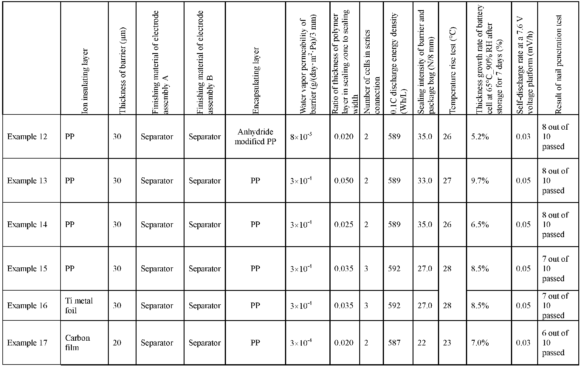


- It can be seen from the foregoing Examples that the output voltage of the battery was increased through series connection according to this application, high energy density and high nail penetration pass rate were maintained, and the self-discharge rate was low. With the barrier of this application, the stability in a humid environment was significantly improved, and the battery of this application maintained a low thickness growth rate, indicating that the battery of the embodiments of this application can prevent water vapor from penetrating into the battery and prolong the service life of the battery. When the water vapor permeability of the barrier is too high, for example, exceeds the range defined in this application, the thickness growth rate of the battery increases significantly, indicating that the water resistance of the battery is reduced, which may affect the service life. When the water vapor permeability of the barrier is required to be low, requirements for materials are significantly increased, which will lead to a significant increase in manufacturing costs. When the ratio of the sealing thickness to the sealing width is lower than the lower limit of the range defined in this application, for example, the sealing width of the battery is excessively large, although the sealing intensity is increased, the energy density of the battery will be significantly reduced, and when the sealing thickness of the battery is excessively small, the sealing intensity is significantly reduced. When the ratio of the sealing thickness to the sealing width is higher than the upper limit of the range defined in this application, for example, when the sealing thickness is excessively large, the growth rate of the battery increases significantly. Without being limited to any theory, the applicant believes that excessive sealing thickness may cause water vapor to penetrate into the battery from the sealing zone, thereby reducing the water resistance of the battery.
- The foregoing descriptions are merely preferred embodiments of the present invention, but are not intended to limit the present invention. Any modification, equivalent replacement, or improvement made without departing from the spirit and principle of the present invention shall fall within the protection scope of the present invention.
Claims (10)
- An electrochemical apparatus, comprising a barrier, wherein the barrier is hermetically connected to an outer package, standalone chambers are formed at two sides of the barrier respectively, each chamber encapsulates an electrode assembly and an electrolyte, electrode assemblies in adjacent chambers are connected in series by tabs, and the barrier comprises an ion insulating layer;water permeability of the barrier is less than or equal to 10-3 g/(day·m2·Pa)/3 mm; andsealing thickness T and sealing width W of a seal between the barrier and the outer package satisfy 0.01≤T/W≤0.05.
- The electrochemical apparatus according to claim 1, wherein the ion insulating layer is made of at least one of a polymer material, a metal material, and a carbon material.
- The electrochemical apparatus according to claim 2, wherein the polymer material comprises at least one of polyethylene terephthalate, polybutylene terephthalate, polyethylene naphthalate, polyether ether ketone, polyimide, polyamide, polyethylene glycol, polyamide imide amine, polycarbonate, cyclic polyolefin, polyphenylene sulfide, polyvinyl acetate, polytetrafluoroethylene, polymethylene naphthalene, polyvinylidene fluoride, polyethylene naphthalate, polypropylene carbonate ester, poly(vinylidene fluoride-hexafluoropropylene), poly(vinylidene fluoride-co-chlorotrifluoroethylene), silicone, vinylon, polypropylene, anhydride modified polypropylene, polyethylene, ethylene-acetic acid ethylene copolymer, ethylene-ethyl acrylate copolymer, ethylene-acrylic acid copolymer, ethylene-vinyl alcohol copolymer, polyvinyl chloride, polystyrene, polyether nitrile, polyurethane, polyphenylene ether, polyester, polysulfone, and non-crystalline α-olefin copolymer and its derivatives;the metal material comprises at least one of Ni, Ti, Cu, Ag, Au, Pt, Fe, Co, Cr, W, Mo, Al, Mg, K, Na, Ca, Sr, Ba, Si, Ge, Sb, Pb, In, Zn, stainless steel, and compositions or alloys thereof; andthe carbon material comprises at least one of carbon felt, carbon film, carbon black, acetylene black, fullerene, conductive graphite film, or graphene film.
- The electrochemical apparatus according to claim 1, wherein the barrier further comprises an encapsulating layer, the encapsulating layer is disposed at a circumferential edge around a surface of the ion insulating layer or on the entire surface of the ion insulating layer, and a material of the encapsulating layer has a melting point ranging from 120°C to 160°C.
- The electrochemical apparatus according to claim 4, wherein the encapsulating layer comprises at least one of polypropylene, acid anhydride modified polypropylene, polyethylene, ethylene-vinyl acetate copolymer, ethylene-ethyl acrylate copolymer, ethylene-acrylic acid copolymer, ethylene-vinyl alcohol copolymer, polyvinyl chloride, polystyrene, polyether nitrile, polyurethane, polyamide, polyester, and amorphous α-olefin copolymer and its derivatives.
- The electrochemical apparatus according to claim 1, wherein width of the barrier ranges from 6 µm to 100 µm.
- The electrochemical apparatus according to claim 1, wherein the ion insulating layer is a single-layer or multi-layer structure.
- The electrochemical apparatus according to claim 1, having at least one of the following characteristics:(a) the water permeability of the barrier is less than or equal to 10-4 g/(day·m2·Pa)/3 mm;(b) thickness of the barrier ranges from 10 µm to 40 µm; and(c) a material of the ion insulating layer has a melting point higher than or equal to 165°C.
- The electrochemical apparatus according to claim 1, wherein a structure of the electrode assembly comprises a winding structure or a laminated structure.
- An electronic apparatus, comprising the electrochemical apparatus according to any one of claims 1 to 9.
Applications Claiming Priority (1)
| Application Number | Priority Date | Filing Date | Title |
|---|---|---|---|
| PCT/CN2020/099509 WO2022000328A1 (en) | 2020-06-30 | 2020-06-30 | Electrochemical device and electronic device |
Publications (2)
| Publication Number | Publication Date |
|---|---|
| EP4020692A1 true EP4020692A1 (en) | 2022-06-29 |
| EP4020692A4 EP4020692A4 (en) | 2022-11-09 |
Family
ID=79317284
Family Applications (1)
| Application Number | Title | Priority Date | Filing Date |
|---|---|---|---|
| EP20943015.6A Pending EP4020692A4 (en) | 2020-06-30 | 2020-06-30 | Electrochemical device and electronic device |
Country Status (5)
| Country | Link |
|---|---|
| US (1) | US20220223948A1 (en) |
| EP (1) | EP4020692A4 (en) |
| JP (1) | JP7333474B2 (en) |
| CN (2) | CN114258610B (en) |
| WO (1) | WO2022000328A1 (en) |
Families Citing this family (8)
| Publication number | Priority date | Publication date | Assignee | Title |
|---|---|---|---|---|
| CN116982210A (en) * | 2022-02-24 | 2023-10-31 | 宁德新能源科技有限公司 | Electrochemical devices and electronic equipment |
| CN115956324B (en) * | 2022-02-28 | 2025-01-28 | 宁德新能源科技有限公司 | Separator for electrochemical device, electrochemical device and electrical equipment |
| CN114678636B (en) * | 2022-03-28 | 2024-07-02 | 宁德新能源科技有限公司 | Electrochemical device and electricity utilization device |
| WO2023184400A1 (en) * | 2022-03-31 | 2023-10-05 | 宁德新能源科技有限公司 | Electrochemical apparatus and electronic device |
| CN116802914B (en) * | 2022-04-12 | 2025-08-08 | 宁德新能源科技有限公司 | Electrochemical device and electronic equipment |
| WO2023197160A1 (en) * | 2022-04-12 | 2023-10-19 | 宁德新能源科技有限公司 | Electrochemical apparatus and electronic device |
| WO2023216187A1 (en) * | 2022-05-12 | 2023-11-16 | 宁德新能源科技有限公司 | Electrochemical device and electronic device |
| WO2026053860A1 (en) * | 2024-09-04 | 2026-03-12 | 大日本印刷株式会社 | Separation film for electric power storage device and method for manufacturing same, and electric power storage device and method for manufacturing same |
Family Cites Families (11)
| Publication number | Priority date | Publication date | Assignee | Title |
|---|---|---|---|---|
| US6632538B1 (en) * | 1998-02-05 | 2003-10-14 | Dai Nippon Printing Co., Ltd. | Sheet for cell and cell device |
| JP2005340144A (en) * | 2004-05-31 | 2005-12-08 | Nissan Motor Co Ltd | Secondary battery and manufacturing method thereof |
| JP2007080733A (en) * | 2005-09-15 | 2007-03-29 | Sharp Corp | Non-aqueous power storage device |
| JP5761742B2 (en) * | 2011-03-31 | 2015-08-12 | Necエナジーデバイス株式会社 | Battery pack |
| JP5956798B2 (en) * | 2012-03-23 | 2016-07-27 | 富士重工業株式会社 | Battery module |
| KR101732285B1 (en) * | 2012-11-09 | 2017-05-02 | 닛산 지도우샤 가부시키가이샤 | Assembled battery and method for manufacturing assembled battery |
| CN105009353B (en) * | 2013-03-05 | 2017-05-03 | 神华集团有限责任公司 | Bipolar battery, manufacturing method thereof and vehicle |
| CN104143652B (en) * | 2013-05-09 | 2016-05-04 | 神华集团有限责任公司 | Bipolar battery and method for packing thereof |
| CN203377299U (en) * | 2013-07-23 | 2014-01-01 | 东莞新能源科技有限公司 | Electrochemical device |
| WO2020017459A1 (en) * | 2018-07-20 | 2020-01-23 | マクセルホールディングス株式会社 | Battery roll and method for manufacturing same |
| WO2020153456A1 (en) * | 2019-01-23 | 2020-07-30 | 大日本印刷株式会社 | Exterior material for all-solid-state battery, method for manufacturing same, and all-solid-state battery |
-
2020
- 2020-06-30 EP EP20943015.6A patent/EP4020692A4/en active Pending
- 2020-06-30 CN CN202080053282.5A patent/CN114258610B/en active Active
- 2020-06-30 WO PCT/CN2020/099509 patent/WO2022000328A1/en not_active Ceased
- 2020-06-30 CN CN202411530435.7A patent/CN119340451A/en active Pending
- 2020-06-30 JP JP2022518848A patent/JP7333474B2/en active Active
-
2022
- 2022-03-31 US US17/709,545 patent/US20220223948A1/en active Pending
Also Published As
| Publication number | Publication date |
|---|---|
| CN119340451A (en) | 2025-01-21 |
| JP2022549657A (en) | 2022-11-28 |
| EP4020692A4 (en) | 2022-11-09 |
| WO2022000328A1 (en) | 2022-01-06 |
| US20220223948A1 (en) | 2022-07-14 |
| CN114258610A (en) | 2022-03-29 |
| CN114258610B (en) | 2024-11-19 |
| JP7333474B2 (en) | 2023-08-24 |
Similar Documents
| Publication | Publication Date | Title |
|---|---|---|
| JP7196364B2 (en) | Secondary batteries and battery modules, battery packs and devices containing such secondary batteries | |
| US20220223948A1 (en) | Electrochemical apparatus and electronic apparatus | |
| US20220158246A1 (en) | Lithium-ion battery and apparatus | |
| US20220223899A1 (en) | Partition for electrochemical apparatus, electrochemical apparatus, and electronic apparatus | |
| US12237542B2 (en) | Electrochemical device and electronic device containing the same | |
| US12438243B2 (en) | Electrochemical device and electronic device | |
| CN1285087A (en) | Preparation method of thin battery and thin battery | |
| US20230246272A1 (en) | Electrochemical apparatus and electronic apparatus | |
| US20220223968A1 (en) | Partition plate for use in electrochemical device, electrochemical device, and electronic device | |
| WO2023197946A1 (en) | Positive electrode plate, secondary battery, electronic device, and mobile equipment | |
| WO2025020844A1 (en) | Battery and electronic device | |
| CN120473474B (en) | Battery monomer, battery device and electric equipment | |
| EP4682997A1 (en) | Secondary battery and electronic apparatus | |
| EP3605667A1 (en) | Lithium ion secondary battery, and manufacturing method and inspection method for negative electrode for lithium ion secondary battery | |
| EP4156355A1 (en) | Separator, electrochemical device comprising same, and electronic device | |
| CN1412881A (en) | Method for mfg. lithium ion polymer cell | |
| US20240145791A1 (en) | Secondary battery and preparation method thereof, battery module, battery pack, and electric apparatus | |
| WO2023164914A1 (en) | Electrochemical device and electronic device | |
| CN119447207A (en) | Battery cell and preparation method thereof, soft-pack lithium-ion battery and application thereof | |
| JP2000228192A (en) | Non-aqueous electrolyte battery |
Legal Events
| Date | Code | Title | Description |
|---|---|---|---|
| STAA | Information on the status of an ep patent application or granted ep patent |
Free format text: STATUS: THE INTERNATIONAL PUBLICATION HAS BEEN MADE |
|
| PUAI | Public reference made under article 153(3) epc to a published international application that has entered the european phase |
Free format text: ORIGINAL CODE: 0009012 |
|
| STAA | Information on the status of an ep patent application or granted ep patent |
Free format text: STATUS: REQUEST FOR EXAMINATION WAS MADE |
|
| 17P | Request for examination filed |
Effective date: 20220325 |
|
| AK | Designated contracting states |
Kind code of ref document: A1 Designated state(s): AL AT BE BG CH CY CZ DE DK EE ES FI FR GB GR HR HU IE IS IT LI LT LU LV MC MK MT NL NO PL PT RO RS SE SI SK SM TR |
|
| A4 | Supplementary search report drawn up and despatched |
Effective date: 20221011 |
|
| RIC1 | Information provided on ipc code assigned before grant |
Ipc: H01M 50/471 20210101ALI20221005BHEP Ipc: H01M 50/112 20210101ALI20221005BHEP Ipc: H01M 50/293 20210101ALI20221005BHEP Ipc: H01M 50/289 20210101AFI20221005BHEP |
|
| DAV | Request for validation of the european patent (deleted) | ||
| DAX | Request for extension of the european patent (deleted) |