EP4020667A1 - Vehicle battery pack - Google Patents
Vehicle battery pack Download PDFInfo
- Publication number
- EP4020667A1 EP4020667A1 EP21207752.3A EP21207752A EP4020667A1 EP 4020667 A1 EP4020667 A1 EP 4020667A1 EP 21207752 A EP21207752 A EP 21207752A EP 4020667 A1 EP4020667 A1 EP 4020667A1
- Authority
- EP
- European Patent Office
- Prior art keywords
- duct
- battery modules
- vehicle
- blower
- battery
- Prior art date
- Legal status (The legal status is an assumption and is not a legal conclusion. Google has not performed a legal analysis and makes no representation as to the accuracy of the status listed.)
- Pending
Links
- 238000001816 cooling Methods 0.000 claims abstract description 52
- 238000011144 upstream manufacturing Methods 0.000 claims description 22
- 238000013459 approach Methods 0.000 claims description 6
- 230000007423 decrease Effects 0.000 claims description 3
- 239000011159 matrix material Substances 0.000 description 7
- 239000002184 metal Substances 0.000 description 5
- 230000006866 deterioration Effects 0.000 description 4
- 230000007246 mechanism Effects 0.000 description 3
- 230000001154 acute effect Effects 0.000 description 2
- 238000007599 discharging Methods 0.000 description 2
- 239000000463 material Substances 0.000 description 2
- 239000011347 resin Substances 0.000 description 2
- 229920005989 resin Polymers 0.000 description 2
- 230000002730 additional effect Effects 0.000 description 1
- 230000000694 effects Effects 0.000 description 1
- 238000000034 method Methods 0.000 description 1
- 238000003466 welding Methods 0.000 description 1
Images




Classifications
-
- H—ELECTRICITY
- H01—ELECTRIC ELEMENTS
- H01M—PROCESSES OR MEANS, e.g. BATTERIES, FOR THE DIRECT CONVERSION OF CHEMICAL ENERGY INTO ELECTRICAL ENERGY
- H01M10/00—Secondary cells; Manufacture thereof
- H01M10/60—Heating or cooling; Temperature control
- H01M10/62—Heating or cooling; Temperature control specially adapted for specific applications
- H01M10/625—Vehicles
-
- B—PERFORMING OPERATIONS; TRANSPORTING
- B60—VEHICLES IN GENERAL
- B60K—ARRANGEMENT OR MOUNTING OF PROPULSION UNITS OR OF TRANSMISSIONS IN VEHICLES; ARRANGEMENT OR MOUNTING OF PLURAL DIVERSE PRIME-MOVERS IN VEHICLES; AUXILIARY DRIVES FOR VEHICLES; INSTRUMENTATION OR DASHBOARDS FOR VEHICLES; ARRANGEMENTS IN CONNECTION WITH COOLING, AIR INTAKE, GAS EXHAUST OR FUEL SUPPLY OF PROPULSION UNITS IN VEHICLES
- B60K1/00—Arrangement or mounting of electrical propulsion units
- B60K1/04—Arrangement or mounting of electrical propulsion units of the electric storage means for propulsion
-
- B—PERFORMING OPERATIONS; TRANSPORTING
- B60—VEHICLES IN GENERAL
- B60L—PROPULSION OF ELECTRICALLY-PROPELLED VEHICLES; SUPPLYING ELECTRIC POWER FOR AUXILIARY EQUIPMENT OF ELECTRICALLY-PROPELLED VEHICLES; ELECTRODYNAMIC BRAKE SYSTEMS FOR VEHICLES IN GENERAL; MAGNETIC SUSPENSION OR LEVITATION FOR VEHICLES; MONITORING OPERATING VARIABLES OF ELECTRICALLY-PROPELLED VEHICLES; ELECTRIC SAFETY DEVICES FOR ELECTRICALLY-PROPELLED VEHICLES
- B60L50/00—Electric propulsion with power supplied within the vehicle
- B60L50/50—Electric propulsion with power supplied within the vehicle using propulsion power supplied by batteries or fuel cells
- B60L50/60—Electric propulsion with power supplied within the vehicle using propulsion power supplied by batteries or fuel cells using power supplied by batteries
- B60L50/64—Constructional details of batteries specially adapted for electric vehicles
-
- B—PERFORMING OPERATIONS; TRANSPORTING
- B60—VEHICLES IN GENERAL
- B60L—PROPULSION OF ELECTRICALLY-PROPELLED VEHICLES; SUPPLYING ELECTRIC POWER FOR AUXILIARY EQUIPMENT OF ELECTRICALLY-PROPELLED VEHICLES; ELECTRODYNAMIC BRAKE SYSTEMS FOR VEHICLES IN GENERAL; MAGNETIC SUSPENSION OR LEVITATION FOR VEHICLES; MONITORING OPERATING VARIABLES OF ELECTRICALLY-PROPELLED VEHICLES; ELECTRIC SAFETY DEVICES FOR ELECTRICALLY-PROPELLED VEHICLES
- B60L50/00—Electric propulsion with power supplied within the vehicle
- B60L50/50—Electric propulsion with power supplied within the vehicle using propulsion power supplied by batteries or fuel cells
- B60L50/60—Electric propulsion with power supplied within the vehicle using propulsion power supplied by batteries or fuel cells using power supplied by batteries
- B60L50/66—Arrangements of batteries
-
- B—PERFORMING OPERATIONS; TRANSPORTING
- B60—VEHICLES IN GENERAL
- B60L—PROPULSION OF ELECTRICALLY-PROPELLED VEHICLES; SUPPLYING ELECTRIC POWER FOR AUXILIARY EQUIPMENT OF ELECTRICALLY-PROPELLED VEHICLES; ELECTRODYNAMIC BRAKE SYSTEMS FOR VEHICLES IN GENERAL; MAGNETIC SUSPENSION OR LEVITATION FOR VEHICLES; MONITORING OPERATING VARIABLES OF ELECTRICALLY-PROPELLED VEHICLES; ELECTRIC SAFETY DEVICES FOR ELECTRICALLY-PROPELLED VEHICLES
- B60L58/00—Methods or circuit arrangements for monitoring or controlling batteries or fuel cells, specially adapted for electric vehicles
- B60L58/10—Methods or circuit arrangements for monitoring or controlling batteries or fuel cells, specially adapted for electric vehicles for monitoring or controlling batteries
- B60L58/24—Methods or circuit arrangements for monitoring or controlling batteries or fuel cells, specially adapted for electric vehicles for monitoring or controlling batteries for controlling the temperature of batteries
- B60L58/26—Methods or circuit arrangements for monitoring or controlling batteries or fuel cells, specially adapted for electric vehicles for monitoring or controlling batteries for controlling the temperature of batteries by cooling
-
- H—ELECTRICITY
- H01—ELECTRIC ELEMENTS
- H01M—PROCESSES OR MEANS, e.g. BATTERIES, FOR THE DIRECT CONVERSION OF CHEMICAL ENERGY INTO ELECTRICAL ENERGY
- H01M10/00—Secondary cells; Manufacture thereof
- H01M10/60—Heating or cooling; Temperature control
- H01M10/61—Types of temperature control
- H01M10/617—Types of temperature control for achieving uniformity or desired distribution of temperature
-
- H—ELECTRICITY
- H01—ELECTRIC ELEMENTS
- H01M—PROCESSES OR MEANS, e.g. BATTERIES, FOR THE DIRECT CONVERSION OF CHEMICAL ENERGY INTO ELECTRICAL ENERGY
- H01M10/00—Secondary cells; Manufacture thereof
- H01M10/60—Heating or cooling; Temperature control
- H01M10/65—Means for temperature control structurally associated with the cells
- H01M10/656—Means for temperature control structurally associated with the cells characterised by the type of heat-exchange fluid
- H01M10/6561—Gases
- H01M10/6563—Gases with forced flow, e.g. by blowers
-
- H—ELECTRICITY
- H01—ELECTRIC ELEMENTS
- H01M—PROCESSES OR MEANS, e.g. BATTERIES, FOR THE DIRECT CONVERSION OF CHEMICAL ENERGY INTO ELECTRICAL ENERGY
- H01M10/00—Secondary cells; Manufacture thereof
- H01M10/60—Heating or cooling; Temperature control
- H01M10/65—Means for temperature control structurally associated with the cells
- H01M10/656—Means for temperature control structurally associated with the cells characterised by the type of heat-exchange fluid
- H01M10/6567—Liquids
- H01M10/6568—Liquids characterised by flow circuits, e.g. loops, located externally to the cells or cell casings
-
- B—PERFORMING OPERATIONS; TRANSPORTING
- B60—VEHICLES IN GENERAL
- B60K—ARRANGEMENT OR MOUNTING OF PROPULSION UNITS OR OF TRANSMISSIONS IN VEHICLES; ARRANGEMENT OR MOUNTING OF PLURAL DIVERSE PRIME-MOVERS IN VEHICLES; AUXILIARY DRIVES FOR VEHICLES; INSTRUMENTATION OR DASHBOARDS FOR VEHICLES; ARRANGEMENTS IN CONNECTION WITH COOLING, AIR INTAKE, GAS EXHAUST OR FUEL SUPPLY OF PROPULSION UNITS IN VEHICLES
- B60K1/00—Arrangement or mounting of electrical propulsion units
- B60K1/04—Arrangement or mounting of electrical propulsion units of the electric storage means for propulsion
- B60K2001/0405—Arrangement or mounting of electrical propulsion units of the electric storage means for propulsion characterised by their position
- B60K2001/0438—Arrangement under the floor
-
- H—ELECTRICITY
- H01—ELECTRIC ELEMENTS
- H01M—PROCESSES OR MEANS, e.g. BATTERIES, FOR THE DIRECT CONVERSION OF CHEMICAL ENERGY INTO ELECTRICAL ENERGY
- H01M2220/00—Batteries for particular applications
- H01M2220/20—Batteries in motive systems, e.g. vehicle, ship, plane
-
- H—ELECTRICITY
- H01—ELECTRIC ELEMENTS
- H01M—PROCESSES OR MEANS, e.g. BATTERIES, FOR THE DIRECT CONVERSION OF CHEMICAL ENERGY INTO ELECTRICAL ENERGY
- H01M50/00—Constructional details or processes of manufacture of the non-active parts of electrochemical cells other than fuel cells, e.g. hybrid cells
- H01M50/20—Mountings; Secondary casings or frames; Racks, modules or packs; Suspension devices; Shock absorbers; Transport or carrying devices; Holders
- H01M50/204—Racks, modules or packs for multiple batteries or multiple cells
-
- H—ELECTRICITY
- H01—ELECTRIC ELEMENTS
- H01M—PROCESSES OR MEANS, e.g. BATTERIES, FOR THE DIRECT CONVERSION OF CHEMICAL ENERGY INTO ELECTRICAL ENERGY
- H01M50/00—Constructional details or processes of manufacture of the non-active parts of electrochemical cells other than fuel cells, e.g. hybrid cells
- H01M50/20—Mountings; Secondary casings or frames; Racks, modules or packs; Suspension devices; Shock absorbers; Transport or carrying devices; Holders
- H01M50/249—Mountings; Secondary casings or frames; Racks, modules or packs; Suspension devices; Shock absorbers; Transport or carrying devices; Holders specially adapted for aircraft or vehicles, e.g. cars or trains
-
- Y—GENERAL TAGGING OF NEW TECHNOLOGICAL DEVELOPMENTS; GENERAL TAGGING OF CROSS-SECTIONAL TECHNOLOGIES SPANNING OVER SEVERAL SECTIONS OF THE IPC; TECHNICAL SUBJECTS COVERED BY FORMER USPC CROSS-REFERENCE ART COLLECTIONS [XRACs] AND DIGESTS
- Y02—TECHNOLOGIES OR APPLICATIONS FOR MITIGATION OR ADAPTATION AGAINST CLIMATE CHANGE
- Y02E—REDUCTION OF GREENHOUSE GAS [GHG] EMISSIONS, RELATED TO ENERGY GENERATION, TRANSMISSION OR DISTRIBUTION
- Y02E60/00—Enabling technologies; Technologies with a potential or indirect contribution to GHG emissions mitigation
- Y02E60/10—Energy storage using batteries
Definitions
- the present invention relates to a vehicle battery pack that has multiple battery modules, a cooling device configured to cool the multiple battery modules, and a battery case for accommodating the multiple battery modules and the cooling device.
- a vehicle battery pack may be mounted to electrically drive the vehicle, for example.
- a vehicle battery pack has multiple battery modules disposed therein, a battery cooling device capable of cooling the multiple battery modules, and a battery case for accommodating the multiple battery modules and the cooling device.
- the cooling device may be configured to cool the multiple battery modules using air sent from a blower. The cooling device is required to send the air from the blower efficiently to cool the multiple battery modules efficiently.
- Examples of such a vehicle battery pack include a battery pack that has: a battery (battery module); a battery case for accommodating the battery; a cooling unit (cooling device) that is provided on one end side in the longitudinal direction of the battery case and supplies cooling air to the battery case; and an air duct formed so as to allow passage of the cooling air, in which: the air duct has a main air duct provided in a central portion in the transverse direction of the battery case along the longitudinal direction of the battery case, and multiple distribution ducts that are connected to the other end portion of the main air duct located on the other end side in the longitudinal direction of the battery case to distribute cooling air in a direction intersecting the main air duct; and cooling air supplied from the cooling unit vertically circulates inside of the battery case through the air duct and returns to the cooling unit (see Patent Literature 1, for example).
- the cooling air is sent from one end side to the other end side in the longitudinal direction of the battery case through the main air duct, and is then returned from the other end side to the one end side in the longitudinal direction of the battery case so as to cool the multiple battery modules located along the multiple distribution ducts.
- a vehicle battery pack mounted on a vehicle, the vehicle battery pack including: multiple battery modules; a cooling device configured to cool the multiple battery modules; and a battery case that accommodates the multiple battery modules and the cooling device, in which: the cooling device has a blower as a supply source of air sent to cool the multiple battery modules, and a duct assembly having an internal space formed so as to allow passage of air from the blower; the duct assembly includes a first duct connected to the blower, an intersecting connection duct connected to the first duct, and a second duct connected to the intersecting connection duct; the first duct and the intersecting connection duct are disposed in horizontal directions that are directions extending in a longitudinal direction and a width direction of the vehicle; the second duct has multiple second duct bodies extending from the intersecting connection duct so as to split air having passed the intersecting connection duct from the first duct; the multiple battery modules include multiple first battery modules disposed in an area located below the first duct so as to
- multiple battery modules can be cooled efficiently.
- a vehicle battery pack according to an embodiment will be described together with a vehicle in which the vehicle battery pack is mounted.
- the vehicle on which the vehicle battery pack according to the present embodiment (hereinafter simply referred to as "battery pack" as necessary) is mounted in an electric automobile.
- the vehicle may be an electrically powered vehicle other than an electric automobile in which a battery pack can be mounted.
- the left and right respectively refer to the left and right when facing the vehicle front.
- the horizontal direction refers to directions extending along the longitudinal direction and the width direction of the vehicle.
- the upper side of the vehicle and the lower side of the vehicle may simply be referred to as the upper side and the lower side, respectively.
- FIG. 1 An overview of a battery pack 10 and a vehicle according to the present embodiment will be provided with reference to Figures 1 to 7 . That is, the battery pack 10 and the vehicle according to the present embodiment are generally configured in the following manner. As illustrated in Figures 1 and 2 , the battery pack 10 is mounted on the vehicle.
- the battery pack 10 has a battery module group 11 including multiple battery modules 20, 21.
- the battery pack 10 has a cooling device 12 configured to cool the multiple battery modules 20, 21.
- the cooling device 12 has a blower 30 as a supply source of air sent to cool the multiple battery modules 20, 21.
- the cooling device 12 has a duct assembly 12a that has an internal space formed so as to allow passage of air from the blower 30.
- the battery pack 10 has a battery case 13 for accommodating the battery module group 11 and the cooling device 12.
- the duct assembly 12a has a first duct 40 connected to the blower 30.
- the duct assembly 12a has an intersecting connection duct 50 connected to the first duct 40.
- the duct assembly 12a has a second duct 60 connected to the intersecting connection duct 50.
- the first duct 40 and the intersecting connection duct 50 are disposed along the horizontal direction.
- the second duct 60 has multiple second duct bodies 61 extending from the intersecting connection duct 50 so as to split the air having passed through the intersecting connection duct 50 from the first duct 40.
- the battery module group 11 has multiple first battery modules 20 disposed in an area (hereinafter referred to as "first battery area" as needed) 10a located below the first duct 40 so as to vertically face the first duct 40.
- the battery module group 11 has multiple second battery modules 21 disposed so as to be shifted in at least one direction of the horizontal directions from the multiple first battery modules 20.
- the first duct 40 has a through hole 40b that penetrates a bottom wall 40a of the first duct 40 so as to connect gaps 20a, 20b between at least one set of adjacent first battery modules 20 with the first duct 40 to supply air to the gaps 20a, 20b from the first duct 40.
- the multiple second duct bodies 61 are configured to send air toward the multiple second battery modules 21 through the multiple second duct bodies 61.
- the battery pack 10 and the vehicle according to the present embodiment can be generally configured in the following manner.
- the cross section of the internal space of the second duct body 61 is smaller than the cross section of the internal space of the first duct 40.
- the cross section of the internal space of the first duct 40 decreases as the cross section approaches the intersecting connection duct 50 in a direction from the blower 30 toward the intersecting connection duct 50.
- the first duct 40 has a downstream end portion 41 in the flow direction of air passing therethrough.
- the downstream end portion 41 of the first duct 40 is connected to the intersecting connection duct 50.
- the downstream end portion 41 of the first duct 40 is formed such that, in plan view, the width of the downstream end portion 41 increases toward the intersecting connection duct 50 in the direction from the blower 30 toward the intersecting connection duct 50.
- the blower 30, the first duct 40, the intersecting connection duct 50, and the second duct 60 are located above the multiple first battery modules 20 so as to vertically face the multiple first battery modules 20.
- the blower 30 has a connection portion 31 connected to an upstream end portion 42 in the flow direction of the first duct 40.
- the connection portion 31 of the blower 30 has an air outlet 31a opened in one direction of the horizontal directions to send air into the internal space of the first duct 40.
- the multiple second duct bodies 61 include two second duct bodies 61 extending in one and the other specific horizontal directions from the intersecting connection duct 50.
- the second duct 60 is located closer to one side in a direction substantially orthogonal to the specific direction than the blower 30.
- the downstream end portion 41 of the first duct 40 extends in the direction substantially orthogonal to the specific direction.
- the specific direction is the width direction.
- the direction substantially orthogonal to the specific direction is the longitudinal direction.
- One side in the direction substantially orthogonal to the specific direction is the front.
- the specific direction may be a horizontal direction other than the width direction.
- the specific direction may be the longitudinal direction.
- the one side in the direction substantially orthogonal to the specific direction may be the back.
- connection portion 31 of the blower 30 is disposed so as to be shifted with respect to the downstream end portion 41 of the first duct 40 in the specific direction (width direction in particular).
- the first duct 40 has a tilted portion 43 located between the upstream and downstream end portions 42, 41 in the flow direction thereof.
- the tilted portion 43 is tilted in the specific direction so as to separate from the blower 30, from the other to one side in the direction substantially orthogonal to the specific direction, particularly from the back toward the front.
- a vehicle body 1 has a floor panel 2 that forms a floor (not illustrated) inside the vehicle.
- the battery pack 10 is disposed below the floor panel 2.
- the vehicle body 1 also has two side members 3 spaced apart from each other in the width direction. Each side member 3 has an elongated shape. Each side member 3 is disposed along the longitudinal direction.
- the battery pack 10 is located between the two side members 3 in plan view. The two side members 3 are located below the floor panel 2. An upper surface of each side member 3 is joined to a lower surface of the floor panel 2.
- the vehicle body 1 has a cross member 4 that extends in the width direction so as to connect the two side members 3.
- the cross member 4 is located above the battery pack 10.
- the cross member 4 also extends so as to cross the battery pack 10 in plan view.
- the vehicle body 1 has two cross members 4.
- the vehicle body may have one, three, or more cross members.
- the battery pack 10 can be configured in the following manner.
- the battery pack 10 has a support base 14 configured to support the cooling device 12 from below.
- the support base 14 has a placement portion 80 on which the cooling device 12 is placed.
- the blower 30 of the cooling device 12, the first duct 40, the intersecting connection duct 50, and the second duct 60 are placed on the placement portion 80.
- the first battery area 10a is an area 10a covered with the placement portion 80 from above. Specifically, an upper end surface of the first battery area 10a can be defined by the placement portion 80.
- the support base 14 also has a leg portion 81 that supports the placement portion 80. As illustrated in Figure 5 , a through hole 80a vertically penetrates the placement portion 80.
- the battery pack 10 further has an electric device 15 placed on the placement portion 80.
- the electric device 15 is located in the vicinity of the first duct 40. As illustrated in Figures 3 and 4 , the electric device 15 is spaced apart from the blower 30 in the specific direction (width direction in particular) on the placement portion 80.
- the electric device 15 may be a battery controller 15 that can control charging, discharging, and other operations of the multiple battery modules 20, 21.
- the electric device is not limited to a battery controller.
- the electric device may be an inverter or the like.
- the battery case 13 accommodates the support base 14 and the electric device 15 in addition to the battery module group 11 and the cooling device 12.
- the battery case 13 has an upper case 13a that forms an upper portion thereof.
- the battery case 13 also has a lower case 13b that forms a lower portion thereof.
- the battery case 13 may be configured of metal.
- the upper and lower cases 13a, 13b of the battery case 13 may be formed as a press-formed part including metal plate materials.
- the battery case may be configured of resin.
- at least one of the upper and lower cases of the battery case may be formed as a resin-formed part.
- the battery pack 10 is configured to be attached to the two side members 3.
- the battery pack 10 has multiple attachment mechanisms 16 configured to attach the battery pack 10 to each side member 3.
- the battery pack 10 has the multiple attachment mechanisms 16 configured to attach the battery case 13 to the vehicle body 1.
- the battery pack may have a single attachment mechanism configured to attach the battery pack to each side member.
- the battery module group 11 can be configured in the following manner.
- the battery modules 20, 21 of the battery module group 11 enable charging and discharging of electric power used as electric power for driving the vehicle.
- the multiple battery modules 20, 21 are spaced apart from one another in the horizontal direction.
- the multiple first battery modules 20 are arranged in a matrix including multiple rows and multiple columns in the first battery area 10a.
- the multiple rows extend along the specific direction (width direction in particular).
- the multiple columns extend along the direction (longitudinal direction in particular) substantially orthogonal to the specific direction.
- four first battery modules 20 may be arranged in a matrix of two rows and two columns.
- the arrangement of the multiple first battery modules is not limited to the above.
- the multiple first battery modules may be arranged in one line.
- the gap 20a is formed between at least two sets of first battery modules 20 adjacent to each other in the specific direction (width direction in particular), and the gap 20b is formed between at least two sets of first battery modules 20 adjacent to each other in the direction (longitudinal direction in particular) substantially orthogonal to the specific direction.
- the multiple first battery modules 20 are arranged so as to connect all of the gaps 20a, 20b in the first battery area 10a.
- a space is formed between the upper case 13a and the multiple second battery modules 21 in the vertical direction.
- the multiple second battery modules 21 are arranged in a matrix including multiple rows and multiple columns, in an area (hereinafter referred to as "second battery area" as necessary) 10b shifted in one horizontal direction from the first battery area 10a.
- the second battery area 10b is shifted in a direction (longitudinal direction in particular) substantially orthogonal to the specific direction from the first battery area 10a. Furthermore, the second battery area 10b may be shifted to one side (front in particular) in the direction substantially orthogonal to the specific direction from the first battery area 10a.
- the arrangement relationship between the first and second battery areas is not limited to this example.
- the second battery area may be shifted in the specific direction (width direction in particular) from the first battery area.
- the multiple second battery modules 21 are arranged in a matrix including multiple rows and multiple columns in the second battery area 10b.
- the multiple rows are arranged along the specific direction (width direction in particular).
- the multiple columns are arranged along the direction (longitudinal direction in particular) substantially orthogonal to the specific direction.
- eight second battery modules 21 may be arranged in a matrix of two rows and four columns.
- the arrangement of the multiple second battery modules is not limited to the above.
- the multiple second battery modules may be arranged in one line.
- a gap 21a is formed between at least two sets of second battery modules 21 adjacent to each other in the specific direction (width direction in particular), and a gap 21b is formed between at least two sets of second battery modules 21 adjacent to each other in the direction (longitudinal direction in particular) substantially orthogonal to the specific direction.
- the multiple second battery modules 21 are arranged so as to connect all of the gaps 21a, 21b in the second battery area 10b.
- the blower 30 of the cooling device 12 can be configured in the following manner. As illustrated particularly in Figure 5 , the blower 30 of the cooling device 12 is fixed to the placement portion 80 with its bottom surface 30a directly in contact with the placement portion 80. However, the blower may be fixed to a base on the placement portion with its bottom surface in contact with the base.
- connection portion 31 of the blower 30 is connected to the upstream end portion 42 of the first duct 40.
- the blower 30 also has a blower body 32.
- the blower body 32 has a drive source 33 of the blower 30.
- the drive source 33 may be a fan 33 capable of rotating so as to send air from the blower body 32 toward the connection portion 31.
- the center of rotation of the drive source 33 may be substantially the same as a horizontal center 32a of the blower body 32.
- the rotation of the drive source 33 can generate a swirling airflow about the center of rotation in the blower body 32. Such swirling air is discharged from the air outlet 31a of the connection portion 31 of the blower 30.
- the swirling direction of the drive source 33 is clockwise in plan view, and in this case, the swirling airflow is clockwise in plan view.
- the swirling direction of the drive source may be anticlockwise in plan view.
- the swirling airflow is anticlockwise in plan view, and the location of the electric device relative to the blower in the specific direction (width direction in particular) is opposite to that in the case of clockwise swirling.
- connection portion 31 of the blower 30 extends in a direction corresponding to the flow direction of the swirling airflow generated in the blower body 32.
- An extended axis 30b extending in the extension direction of the connection portion 31 is tilted clockwise by a predetermined tilt angle ⁇ from a reference axis 30c passing through the center 32a of the blower body 32 and extending in the specific direction (width direction in particular).
- the tilt angle ⁇ may be an acute angle. However, the tilt angle is not limited to an acute angle.
- connection portion 31 of the blower 30 is disposed on the electric device 15 side of the center 32a of the blower body 32. Furthermore, the connection portion 31 may be disposed in a space between the blower 30 and the electric device 15. The connection portion 31 extends while tilting so as to approach the electric device 15 from the blower body 32 toward the upstream end portion 42 of the first duct 40.
- the duct assembly 12a of the cooling device 12 can be configured in the following manner. As illustrated in Figures 3 and 4 , in the duct assembly 12a of the cooling device 12, the entire upstream end portion 42 of the first duct 40 is disposed so as to overlap the blower 30 and the electric device 15 in the direction (longitudinal direction in particular) substantially orthogonal to the specific direction in plan view. The upstream end portion 42 of the first duct 40 extends in substantially the same direction as the connection portion 31 of the blower 30.
- the upstream end portion 42 of the first duct 40 and top walls 42a, 43a and bottom walls 42b, 43b of the tilted portion 43 may be formed substantially parallel to a later-described imaginary plane P (indicated by imaginary line in Figure 5 ).
- Both a top wall 41a and a bottom wall 41b of the downstream end portion 41 of the first duct 40 are tilted with respect to the imaginary plane P.
- each of the top wall 41a and the bottom wall 41b is tilted so as to approach the tilted portion 43 from lower to upper parts thereof.
- the tilted portion 43 of the first duct 40 passes through a space between the blower 30 and the electric device 15.
- the aforementioned through hole 40b is formed in the bottom wall 43b of the tilted portion 43 of the first duct 40.
- the through hole 40b of the first duct 40 is formed so as to be aligned with the through hole 80a of the placement portion 80.
- the through holes 40b, 80a of the first duct 40 and the placement portion 80 are disposed so as to be aligned with an intersection of the gap 20a formed between the first battery modules 20 adjacent to each other in the specific direction (width direction in particular) and the gap 20b formed between the first battery modules 20 adjacent to each other in the direction (longitudinal direction in particular) substantially orthogonal to the specific direction in plan view.
- the duct assembly 12a has a guide duct 70 configured to guide air having entered the through hole 40b from the first duct 40 to the gaps 20a, 20b.
- the guide duct 70 is formed so as to extend along the vertical direction.
- the guide duct 70 has an inlet 70a located at the upper end thereof.
- the air having entered the through hole 40b from the first duct 40 flows into the internal space of the guide duct 70 from the inlet 70a.
- the inlet 70a of the guide duct 70 is disposed so as to be aligned with the through holes 40b, 80a of the first duct 40 and the placement portion 80 in plan view.
- the through hole 40b of the first duct 40, the through hole 80a of the placement portion 80, and the inlet 70a of the guide duct 70 are connected so as to be continuous in the vertical direction.
- the guide duct 70 has two outlets 70b for allowing the air having flowed into the internal space of the guide duct 70 from its inlet 70a to flow into the gaps 20a, 20b.
- the two outlets 70b open to both sides in the specific direction (width direction in particular) in the gap 20b formed between the first battery modules 20 adjacent to each other in the direction (longitudinal direction in particular) substantially orthogonal to the specific direction.
- the guide duct may have two inlets open to both sides in the direction (longitudinal direction in particular) substantially orthogonal to the specific direction in a gap formed between first battery modules adjacent to each other in the specific direction (width direction in particular).
- the intersecting connection duct 50 has an end wall 51 spaced apart from the downstream end portion 41 so as to receive air flowing in from the downstream end portion 41 of the first duct 40 and bend this airflow toward one horizontal direction.
- the intersecting connection duct 50 has an upper tilted wall 52 adjacent to and above the end wall 51.
- the upper tilted wall 52 is tilted so as to approach the downstream end portion 41 of the first duct 40 from lower to upper parts thereof.
- a bottom wall 53 of the intersecting connection duct 50 is in contact with the placement portion 80 in the vertical direction. However, the bottom wall of the intersecting connection duct may be spaced apart from the placement portion in the vertical direction. As illustrated in Figures 3 to 5 , the intersecting connection duct 50 has a joining portion 54 joined to the placement portion 80. The joining portion 54 is located opposite to the downstream end portion 41 with respect to the end wall 51, in the flow direction of air flowing into the intersecting connection duct 50 from the downstream end portion 41 of the first duct 40 in plan view.
- the end wall 51 and the upper tilted wall 52 extend in the specific direction described above (width direction in particular) in plan view.
- the end wall 51 of the intersecting connection duct 50 rises along the vertical direction.
- the bottom wall 53 of the intersecting connection duct 50 is formed along the placement portion 80.
- the bottom wall 53 is disposed so as to substantially coincide with the bottom surface 30a of the blower 30 in the vertical direction.
- the bottom wall of the intersecting connection duct may be disposed below the bottom surface of the blower.
- the bottom wall of the intersecting connection duct may be disposed above the bottom surface of the blower.
- a tilt angle ⁇ of the upper tilted wall 52 with respect to the imaginary plane P is greater than a tilt angle ⁇ , ⁇ of each of the top wall 41a and the bottom wall 41b of the downstream end portion 41 of the first duct 40 with respect to the imaginary plane P.
- the tilt angle of the upper tilted wall with respect to the imaginary plane may be formed to be greater than the tilt angle of only the top wall or the bottom wall of the downstream end portion of the first duct with respect to the imaginary plane.
- the tilt angle of the upper tilted wall with respect to the imaginary plane may be formed to be less than the tilt angle of each of the top wall and the bottom wall of the downstream end portion of the first duct with respect to the imaginary plane.
- the joining portion 54 is formed so as to protrude from the bottom wall 53 of the intersecting connection duct 50.
- the joining portion 54 protrudes in substantially the same direction as the extension direction of the downstream end portion 41 of the first duct 40 in plan view.
- the joining portion 54 is integrated with the intersecting connection duct 50.
- the joining portion 54 is formed along the placement portion 80.
- the joining portion 54 is joined to the placement portion 80 by being fastened with fastening means such as a bolt and a nut.
- fastening means such as a bolt and a nut.
- the joining portion does not necessarily have to be joined to the placement portion by fastening.
- the joining portion may be joined to the placement portion by welding or by other methods.
- the second duct body 61 has an upstream end portion 61a connected to the intersecting connection duct 50 so as to allow air having been deflected in the intersecting connection duct 50 to flow into the second duct body 61.
- the upstream end portion 61a of the second duct body 61 is spaced apart from the placement portion 80 in the vertical direction.
- one upstream end portion 61a of the two second duct bodies 61 is connected to one end of the intersecting connection duct 50 in the specific direction (width direction in particular).
- the other upstream end portion 61a of the two second duct bodies 61 is connected to the other end of the intersecting connection duct 50 in the specific direction (width direction in particular).
- the second duct may have one, three, or more second duct bodies.
- an upstream end portion of the second duct body may be connected to one end of the intersecting connection duct in the specific direction (width direction in particular), and the other end of the intersecting connection duct in the specific direction (width direction in particular) may be closed.
- the upstream end portions of one or more second duct bodies may be connected to one end of the intersecting connection duct in the specific direction (width direction in particular), and the upstream end portions of two or more second duct bodies may be connected to the other end of the intersecting connection duct in the specific direction (width direction in particular).
- each second duct body 61 extends in the specific direction (width direction in particular).
- Each second duct body 61 has an upper tilted wall 61b tilted in a substantially similar manner as the upper tilted wall 52 of the intersecting connection duct 50.
- the upper tilted wall 61b of each second duct body 61 extends in the specific direction (width direction in particular) in a substantially similar manner as the upper tilted wall 52 of the intersecting connection duct 50.
- a bottom wall 61c of each second duct body 61 is disposed at the upper end of the end wall 51 of the intersecting connection duct 50 in the vertical direction.
- the distance between the tilted portion 43 of the first duct 40 and the electric device 15 in the specific direction is less than the distance between the second duct body 61 and the electric device 15 in the direction (longitudinal direction in particular) substantially orthogonal to the specific direction.
- the upper end of the first duct 40 and the upper end of the second duct body 61 are located above the upper end of the electric device 15.
- the duct assembly 12a of the cooling device 12 has two distribution ducts 71 that can send air passing through the two second duct bodies 61 to the gaps 21a, 21b of the multiple second battery modules 21.
- the two distribution ducts 71 are connected to the two second duct bodies 61, respectively.
- the two distribution ducts 71 are disposed along the direction (longitudinal direction in particular) substantially orthogonal to the specific direction.
- the two distribution ducts 71 are disposed on both sides of the second battery area 10b in the specific direction (width direction in particular). Upstream end portions 71a in the flow direction of the two distribution ducts 71 are respectively connected to downstream end portions 61d in the flow direction of the two second duct bodies 61.
- a downstream end portion 71b in the flow direction of each distribution duct 71 is disposed at an intersection of the gap 21a formed between the second battery modules 21 adjacent to each other in the specific direction (width direction in particular) and the gap 21b formed between the second battery modules 21 adjacent to each other in the direction (longitudinal direction in particular) substantially orthogonal to the specific direction in plan view.
- Outlets 71c open to both sides in the direction (longitudinal direction in particular) substantially orthogonal to the specific direction are formed in the downstream end portion 71b of each distribution duct 71.
- At least one outlet 71d open to at least one side in the specific direction (width direction in particular) may be formed in the downstream end portion 71b of each distribution duct 71.
- the air sent to the first duct 40 from the blower 30 is distributed into a portion sent to the gaps 20a, 20b of the first battery modules 20 through the through hole 40b of the first duct 40 and the through hole 80a of the placement portion 80 and then the guide duct 70, and a portion sent to the gaps 21a, 21b of the second battery modules 21 through the intersecting connection duct 50 and the second duct 60 and then the distribution duct 71.
- each such first duct 40, intersecting connection duct 50, second duct body 61 of second duct 60, guide duct 70, and distribution duct 71 (hereinafter collectively referred to as "the ducts" as necessary) is formed using resin.
- each of the ducts may be a resin-molded part.
- at least one of the ducts may be formed by using metal.
- at least one of the ducts may be a press-formed part including metal plate materials.
- the air heated by heat exchange with the battery modules 20, 21 is cooled by exchanging heat with the battery case 13 when flowing along the battery case 13.
- the heated air is cooled by dissipating air to the outside of the battery pack 10 through the battery case 13.
- the air cooled in this manner can cool the battery modules 20, 21 again.
- the battery case 13 be formed to have high thermal conductivity.
- the battery case 13 is preferably formed by using metal, as described above.
- air can be circulated in the following manner. Air is sent to the first duct 40 from the blower 30 and then flows so as to be split into the first and second battery areas 10a, 10b in the first duct 40. The air having flowed to the first and second battery areas 10a, 10b cools the first and second battery modules 20, 21 of the first and second battery areas 10a, 10b, respectively.
- the air heated by cooling the first and second battery modules 20, 21 flows along the battery case 13 around the first and second battery areas 10a, 10b. At this time, the air is cooled by exchanging heat with the battery case 13, and then the air returns to the blower 30 again.
- the vehicle battery pack 10 is the vehicle battery pack 10 mounted on a vehicle including: multiple battery modules 20, 21; the cooling device 12 configured to cool the multiple battery modules 20, 21; and the battery case 13 that accommodates the multiple battery modules 20, 21 and the cooling device 12, in which: the cooling device 12 has the blower 30 as a supply source of air sent to cool the multiple battery modules 20, 21, and the duct assembly 12a having an internal space formed so as to allow passage of air from the blower 30; the duct assembly 12a includes the first duct 40 connected to the blower 30, the intersecting connection duct 50 connected to the first duct 40, and the second duct 60 connected to the intersecting connection duct 50; the first duct 40 and the intersecting connection duct 50 are disposed in horizontal directions that are directions extending in the longitudinal direction and width direction of the vehicle; the second duct 60 has multiple second duct bodies 61 extending from the intersecting connection duct 50 so as to split air having passed the intersecting connection duct 50 from the first duct 40; the multiple battery modules 20, 21 include the
- air can be supplied to the multiple first battery modules 20 through the through hole 40b of the first duct 40 from the blower 30, and air can be supplied to the multiple second battery modules 21 through the first and second ducts 40, 60 from the blower 30.
- cool air can be sent efficiently to the multiple first battery modules 20 located below the first duct 40 and the multiple second battery modules 21 disposed so as to be shifted in at least one of the horizontal directions from the multiple first battery modules 20.
- the multiple battery modules 20, 21 can be cooled efficiently.
- the cross section of the internal space of the second duct body 61 is smaller than the cross section of the internal space of the first duct 40.
- the cross section of the internal space of the first duct 40 decreases as the cross section approaches the intersecting connection duct 50 in a direction from the blower 30 toward the intersecting connection duct 50.
- the air sent to the multiple second battery modules 21 from the first duct 40 through the second duct body 61 can take heat from the multiple second battery modules 21 efficiently.
- the multiple second battery modules 21 can be cooled efficiently.
- the first duct 40 has the downstream end portion 41 in the flow direction of air passing therethrough, and the downstream end portion 41 of the first duct 40 is connected to the intersecting connection duct 50 and is formed such that the width of the downstream end portion 41 increases toward the intersecting connection duct 50 in a direction from the blower 30 toward the intersecting connection duct 50 in plan view.
- the blower 30, the first duct 40, the intersecting connection duct 50, and the second duct 60 are located above the multiple first battery modules 20 so as to face the multiple first battery modules 20 in the vertical direction;
- the blower 30 has the connection portion 31 connected to the upstream end portion 42 of the first duct 40;
- the connection portion 31 of the blower 30 has the air outlet 31a open to one of the horizontal directions so as to send air to the internal space of the first duct 40;
- the second duct 60 is located closer to the front of the vehicle than the blower 30;
- the downstream end portion 41 of the first duct 40 extends in the longitudinal direction of the vehicle;
- the multiple second duct bodies 61 include two second duct bodies 61 extending in one and the other width directions of the vehicle from the intersecting connection duct 50.
- connection portion 31 of the blower 30 having the air outlet 31a is disposed in the vicinity of the through hole 40b of the first duct 40. It is possible to maintain the flow speed of air supplied to the first battery module 20 through the through hole 40b of the first duct 40 to enable efficient cooling of the first battery module 20.
- connection portion 31 of the blower 30 is disposed so as to be shifted with respect to the downstream end portion 41 of the first duct 40 in the width direction of the vehicle; and the first duct 40 has the tilted portion 43 located between the upstream and downstream end portions 42, 41 in the flow direction thereof, and tilted so as to separate from the blower 30 in the width direction of the vehicle from the back of the vehicle toward the front of the vehicle.
- the direction of air sent from the blower 30 to the first duct 40 can be changed smoothly by the tilted portion 43 of the first duct 40, and frictional loss generated when changing the direction of air in the first duct 40 can be reduced. Additionally, the tilted portion 43 can reduce space occupied by the first duct 40. Hence, it is possible to prevent deterioration of flow speed of air passing through the first duct 40. An additional effect is downsizing of the cooling device 12 and therefore downsizing of the battery pack 10.
Landscapes
- Engineering & Computer Science (AREA)
- Chemical & Material Sciences (AREA)
- General Chemical & Material Sciences (AREA)
- Transportation (AREA)
- Mechanical Engineering (AREA)
- Manufacturing & Machinery (AREA)
- Chemical Kinetics & Catalysis (AREA)
- Electrochemistry (AREA)
- Life Sciences & Earth Sciences (AREA)
- Sustainable Development (AREA)
- Sustainable Energy (AREA)
- Power Engineering (AREA)
- Combustion & Propulsion (AREA)
- Secondary Cells (AREA)
- Cooling, Air Intake And Gas Exhaust, And Fuel Tank Arrangements In Propulsion Units (AREA)
- Body Structure For Vehicles (AREA)
- Arrangement Or Mounting Of Propulsion Units For Vehicles (AREA)
- Battery Mounting, Suspending (AREA)
Abstract
[Problem to be Solved] An object of the present invention is to cool multiple battery modules of a vehicle battery pack efficiently.[Solution] A vehicle battery pack of the present invention includes multiple battery modules, a cooling device that cools the multiple battery modules, and a battery case that accommodates the multiple battery modules and the cooling device. The cooling device has a duct assembly that allows passage of air from a blower, a second duct of the duct assembly has multiple second duct bodies that split air having passed through an intersecting connection duct from the first duct, the multiple battery modules include multiple first battery modules disposed in an area below the first duct, and multiple second battery modules disposed so as to be shifted in at least one of the horizontal directions from the multiple first battery modules, the first duct has a through hole that penetrates its bottom wall so as to supply air to a gap between adjacent first battery modules, and the second duct body sends air toward the second battery module.
Description
- The present invention relates to a vehicle battery pack that has multiple battery modules, a cooling device configured to cool the multiple battery modules, and a battery case for accommodating the multiple battery modules and the cooling device.
- In a vehicle such as an electric automobile, a vehicle battery pack may be mounted to electrically drive the vehicle, for example. Typically, a vehicle battery pack has multiple battery modules disposed therein, a battery cooling device capable of cooling the multiple battery modules, and a battery case for accommodating the multiple battery modules and the cooling device. Furthermore, the cooling device may be configured to cool the multiple battery modules using air sent from a blower. The cooling device is required to send the air from the blower efficiently to cool the multiple battery modules efficiently.
- Examples of such a vehicle battery pack include a battery pack that has: a battery (battery module); a battery case for accommodating the battery; a cooling unit (cooling device) that is provided on one end side in the longitudinal direction of the battery case and supplies cooling air to the battery case; and an air duct formed so as to allow passage of the cooling air, in which: the air duct has a main air duct provided in a central portion in the transverse direction of the battery case along the longitudinal direction of the battery case, and multiple distribution ducts that are connected to the other end portion of the main air duct located on the other end side in the longitudinal direction of the battery case to distribute cooling air in a direction intersecting the main air duct; and cooling air supplied from the cooling unit vertically circulates inside of the battery case through the air duct and returns to the cooling unit (see
Patent Literature 1, for example). - [Patent Literature 1]
JP 2011-116321 A - However, in the example of the vehicle battery pack as described above, the cooling air is sent from one end side to the other end side in the longitudinal direction of the battery case through the main air duct, and is then returned from the other end side to the one end side in the longitudinal direction of the battery case so as to cool the multiple battery modules located along the multiple distribution ducts.
- In such a vehicle battery pack, air is warmed by multiple battery modules while passing through multiple distribution ducts and returns to the one end side from the other end side in the longitudinal direction of the battery case. For this reason, the battery modules located on the one end side in the longitudinal direction of the battery case are less likely to be cooled than the battery modules located on the other end side in the longitudinal direction of the battery case. That is, multiple battery modules cannot be cooled efficiently.
- With this being the case, a vehicle battery pack is required to cool multiple battery modules efficiently.
- To solve the problem, a vehicle battery pack according to one aspect is a vehicle battery pack mounted on a vehicle, the vehicle battery pack including: multiple battery modules; a cooling device configured to cool the multiple battery modules; and a battery case that accommodates the multiple battery modules and the cooling device, in which: the cooling device has a blower as a supply source of air sent to cool the multiple battery modules, and a duct assembly having an internal space formed so as to allow passage of air from the blower; the duct assembly includes a first duct connected to the blower, an intersecting connection duct connected to the first duct, and a second duct connected to the intersecting connection duct; the first duct and the intersecting connection duct are disposed in horizontal directions that are directions extending in a longitudinal direction and a width direction of the vehicle; the second duct has multiple second duct bodies extending from the intersecting connection duct so as to split air having passed the intersecting connection duct from the first duct; the multiple battery modules include multiple first battery modules disposed in an area located below the first duct so as to face the first duct in the vertical direction, and multiple second battery modules disposed so as to be shifted in at least one of the horizontal directions from the multiple first battery modules; the first duct has a through hole that penetrates a bottom wall of the first duct so as to connect a gap between at least one set of adjacent first battery modules with the first duct to supply air to the gap from the first duct; and the multiple second duct bodies are configured to send air toward the multiple second battery modules through the multiple second duct bodies.
- With the vehicle battery pack according to one aspect, multiple battery modules can be cooled efficiently.
-
- [
Figure 1] Figure 1 is a plan view schematically illustrating a bottom portion of a vehicle body including a battery pack having a cooling device according to an embodiment. - [
Figure 2] Figure 2 is a plan view schematically illustrating the bottom portion of the vehicle body according to the embodiment with a transparent floor panel. - [
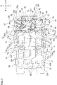
Figure 3] Figure 3 is a plan view schematically illustrating the battery pack according to the embodiment with its upper case removed. - [
Figure 4] Figure 4 is an enlarged view of part W ofFigure 3 . - [
Figure 5] Figure 5 is a cross-sectional view taken along line X-X ofFigure 4 . - [
Figure 6] Figure 6 is a cross-sectional view taken along line Y-Y ofFigure 2 . - [
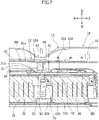
Figure 7] Figure 7 is a cross-sectional view taken along line Z-Z ofFigure 2 . - A vehicle battery pack according to an embodiment will be described together with a vehicle in which the vehicle battery pack is mounted. The vehicle on which the vehicle battery pack according to the present embodiment (hereinafter simply referred to as "battery pack" as necessary) is mounted in an electric automobile. However, the vehicle may be an electrically powered vehicle other than an electric automobile in which a battery pack can be mounted.
- In the drawings used in the description of the present specification, directions based on the vehicle are indicated in the following manner. In
Figures 1 to 6 , the vehicle front and the vehicle back are indicated by one-headed arrow F and one-headed arrow B, respectively. InFigures 1 to 4 and7 , the left and right when facing the vehicle front are indicated by one-headed arrow L and one-headed arrow R, respectively. The vehicle width directions are indicated by one-headed arrow L and one-headed arrow R. Furthermore, inFigures 5 to 7 , the upper side of the vehicle and the lower side of the vehicle are indicated by one-headed arrow U and one-headed arrow D, respectively. - Note that the left and right respectively refer to the left and right when facing the vehicle front. The horizontal direction refers to directions extending along the longitudinal direction and the width direction of the vehicle. In some cases, the upper side of the vehicle and the lower side of the vehicle may simply be referred to as the upper side and the lower side, respectively.
- An overview of a
battery pack 10 and a vehicle according to the present embodiment will be provided with reference toFigures 1 to 7 . That is, thebattery pack 10 and the vehicle according to the present embodiment are generally configured in the following manner. As illustrated inFigures 1 and2 , thebattery pack 10 is mounted on the vehicle. - As illustrated in
Figures 3 to 7 , thebattery pack 10 has abattery module group 11 includingmultiple battery modules battery pack 10 has acooling device 12 configured to cool themultiple battery modules - Referring to
Figures 3 to 7 , thecooling device 12 has ablower 30 as a supply source of air sent to cool themultiple battery modules cooling device 12 has aduct assembly 12a that has an internal space formed so as to allow passage of air from theblower 30. Referring toFigures 1 to 7 , thebattery pack 10 has abattery case 13 for accommodating thebattery module group 11 and thecooling device 12. - The
duct assembly 12a has afirst duct 40 connected to theblower 30. Theduct assembly 12a has an intersectingconnection duct 50 connected to thefirst duct 40. Theduct assembly 12a has asecond duct 60 connected to the intersectingconnection duct 50. Thefirst duct 40 and the intersectingconnection duct 50 are disposed along the horizontal direction. Thesecond duct 60 has multiplesecond duct bodies 61 extending from the intersectingconnection duct 50 so as to split the air having passed through the intersectingconnection duct 50 from thefirst duct 40. - As illustrated in
Figures 5 to 7 , thebattery module group 11 has multiplefirst battery modules 20 disposed in an area (hereinafter referred to as "first battery area" as needed) 10a located below thefirst duct 40 so as to vertically face thefirst duct 40. As illustrated inFigures 3 and4 , thebattery module group 11 has multiplesecond battery modules 21 disposed so as to be shifted in at least one direction of the horizontal directions from the multiplefirst battery modules 20. - As illustrated in
Figure 5 , thefirst duct 40 has a throughhole 40b that penetrates abottom wall 40a of thefirst duct 40 so as to connectgaps first battery modules 20 with thefirst duct 40 to supply air to thegaps first duct 40. As illustrated inFigure 3 , the multiplesecond duct bodies 61 are configured to send air toward the multiplesecond battery modules 21 through the multiplesecond duct bodies 61. - Furthermore, the
battery pack 10 and the vehicle according to the present embodiment can be generally configured in the following manner. Referring toFigures 5 to 7 , the cross section of the internal space of thesecond duct body 61 is smaller than the cross section of the internal space of thefirst duct 40. Referring toFigures 4 and5 , the cross section of the internal space of thefirst duct 40 decreases as the cross section approaches the intersectingconnection duct 50 in a direction from theblower 30 toward the intersectingconnection duct 50. - As illustrated in
Figures 3 and4 , thefirst duct 40 has adownstream end portion 41 in the flow direction of air passing therethrough. Thedownstream end portion 41 of thefirst duct 40 is connected to the intersectingconnection duct 50. Thedownstream end portion 41 of thefirst duct 40 is formed such that, in plan view, the width of thedownstream end portion 41 increases toward the intersectingconnection duct 50 in the direction from theblower 30 toward the intersectingconnection duct 50. - Referring to
Figures 3 to 7 , theblower 30, thefirst duct 40, the intersectingconnection duct 50, and thesecond duct 60 are located above the multiplefirst battery modules 20 so as to vertically face the multiplefirst battery modules 20. As illustrated inFigures 3 to 5 , theblower 30 has aconnection portion 31 connected to anupstream end portion 42 in the flow direction of thefirst duct 40. Theconnection portion 31 of theblower 30 has anair outlet 31a opened in one direction of the horizontal directions to send air into the internal space of thefirst duct 40. - Referring to
Figures 3 to 7 , the multiplesecond duct bodies 61 include twosecond duct bodies 61 extending in one and the other specific horizontal directions from theintersecting connection duct 50. Thesecond duct 60 is located closer to one side in a direction substantially orthogonal to the specific direction than theblower 30. Thedownstream end portion 41 of thefirst duct 40 extends in the direction substantially orthogonal to the specific direction. - Here, the specific direction is the width direction. The direction substantially orthogonal to the specific direction is the longitudinal direction. One side in the direction substantially orthogonal to the specific direction is the front. However, the specific direction may be a horizontal direction other than the width direction. For example, the specific direction may be the longitudinal direction. The one side in the direction substantially orthogonal to the specific direction may be the back.
- As illustrated in
Figures 3 and4 , theconnection portion 31 of theblower 30 is disposed so as to be shifted with respect to thedownstream end portion 41 of thefirst duct 40 in the specific direction (width direction in particular). Thefirst duct 40 has a tiltedportion 43 located between the upstream anddownstream end portions portion 43 is tilted in the specific direction so as to separate from theblower 30, from the other to one side in the direction substantially orthogonal to the specific direction, particularly from the back toward the front. - Referring to
Figures 1 and2 , specifically, the vehicle can be configured in the following manner. Avehicle body 1 has afloor panel 2 that forms a floor (not illustrated) inside the vehicle. Thebattery pack 10 is disposed below thefloor panel 2. - The
vehicle body 1 also has twoside members 3 spaced apart from each other in the width direction. Eachside member 3 has an elongated shape. Eachside member 3 is disposed along the longitudinal direction. Thebattery pack 10 is located between the twoside members 3 in plan view. The twoside members 3 are located below thefloor panel 2. An upper surface of eachside member 3 is joined to a lower surface of thefloor panel 2. - As illustrated in
Figure 2 , thevehicle body 1 has across member 4 that extends in the width direction so as to connect the twoside members 3. Thecross member 4 is located above thebattery pack 10. Thecross member 4 also extends so as to cross thebattery pack 10 in plan view. InFigure 2 , thevehicle body 1 has twocross members 4. However, the vehicle body may have one, three, or more cross members. - Referring to
Figures 1 to 7 , specifically, thebattery pack 10 can be configured in the following manner. Referring toFigures 3 to 7 , thebattery pack 10 has asupport base 14 configured to support thecooling device 12 from below. - The
support base 14 has aplacement portion 80 on which thecooling device 12 is placed. In particular, theblower 30 of thecooling device 12, thefirst duct 40, theintersecting connection duct 50, and thesecond duct 60 are placed on theplacement portion 80. Thefirst battery area 10a is anarea 10a covered with theplacement portion 80 from above. Specifically, an upper end surface of thefirst battery area 10a can be defined by theplacement portion 80. Thesupport base 14 also has aleg portion 81 that supports theplacement portion 80. As illustrated inFigure 5 , a throughhole 80a vertically penetrates theplacement portion 80. - Referring to
Figures 3 to 6 , thebattery pack 10 further has anelectric device 15 placed on theplacement portion 80. Theelectric device 15 is located in the vicinity of thefirst duct 40. As illustrated inFigures 3 and4 , theelectric device 15 is spaced apart from theblower 30 in the specific direction (width direction in particular) on theplacement portion 80. Theelectric device 15 may be abattery controller 15 that can control charging, discharging, and other operations of themultiple battery modules - Referring to
Figures 3 to 7 , thebattery case 13 accommodates thesupport base 14 and theelectric device 15 in addition to thebattery module group 11 and thecooling device 12. Referring toFigures 1 to 7 , thebattery case 13 has anupper case 13a that forms an upper portion thereof. Thebattery case 13 also has alower case 13b that forms a lower portion thereof. - The
battery case 13 may be configured of metal. In this case, the upper andlower cases battery case 13 may be formed as a press-formed part including metal plate materials. However, the battery case may be configured of resin. In this case, at least one of the upper and lower cases of the battery case may be formed as a resin-formed part. - As illustrated in
Figures 1 and2 , thebattery pack 10 is configured to be attached to the twoside members 3. Thebattery pack 10 hasmultiple attachment mechanisms 16 configured to attach thebattery pack 10 to eachside member 3. In other words, thebattery pack 10 has themultiple attachment mechanisms 16 configured to attach thebattery case 13 to thevehicle body 1. However, the battery pack may have a single attachment mechanism configured to attach the battery pack to each side member. - Referring to
Figures 3 to 7 , specifically, thebattery module group 11 can be configured in the following manner. Thebattery modules battery module group 11 enable charging and discharging of electric power used as electric power for driving the vehicle. Themultiple battery modules - Referring to
Figures 5 to 7 , the multiplefirst battery modules 20 are arranged in a matrix including multiple rows and multiple columns in thefirst battery area 10a. The multiple rows extend along the specific direction (width direction in particular). The multiple columns extend along the direction (longitudinal direction in particular) substantially orthogonal to the specific direction. For example, as illustrated inFigures 5 to 7 , fourfirst battery modules 20 may be arranged in a matrix of two rows and two columns. However, the arrangement of the multiple first battery modules is not limited to the above. For example, the multiple first battery modules may be arranged in one line. - In a case in which the multiple
first battery modules 20 are arranged in a matrix, in thefirst battery area 10a, thegap 20a is formed between at least two sets offirst battery modules 20 adjacent to each other in the specific direction (width direction in particular), and thegap 20b is formed between at least two sets offirst battery modules 20 adjacent to each other in the direction (longitudinal direction in particular) substantially orthogonal to the specific direction. The multiplefirst battery modules 20 are arranged so as to connect all of thegaps first battery area 10a. - As illustrated in
Figure 3 , a space is formed between theupper case 13a and the multiplesecond battery modules 21 in the vertical direction. The multiplesecond battery modules 21 are arranged in a matrix including multiple rows and multiple columns, in an area (hereinafter referred to as "second battery area" as necessary) 10b shifted in one horizontal direction from thefirst battery area 10a. - In particular, the
second battery area 10b is shifted in a direction (longitudinal direction in particular) substantially orthogonal to the specific direction from thefirst battery area 10a. Furthermore, thesecond battery area 10b may be shifted to one side (front in particular) in the direction substantially orthogonal to the specific direction from thefirst battery area 10a. However, the arrangement relationship between the first and second battery areas is not limited to this example. For example, the second battery area may be shifted in the specific direction (width direction in particular) from the first battery area. - The multiple
second battery modules 21 are arranged in a matrix including multiple rows and multiple columns in thesecond battery area 10b. The multiple rows are arranged along the specific direction (width direction in particular). The multiple columns are arranged along the direction (longitudinal direction in particular) substantially orthogonal to the specific direction. For example, as illustrated inFigure 3 , eightsecond battery modules 21 may be arranged in a matrix of two rows and four columns. However, the arrangement of the multiple second battery modules is not limited to the above. For example, the multiple second battery modules may be arranged in one line. - In a case in which the multiple
second battery modules 21 are arranged in a matrix, in thesecond battery area 10b, agap 21a is formed between at least two sets ofsecond battery modules 21 adjacent to each other in the specific direction (width direction in particular), and agap 21b is formed between at least two sets ofsecond battery modules 21 adjacent to each other in the direction (longitudinal direction in particular) substantially orthogonal to the specific direction. The multiplesecond battery modules 21 are arranged so as to connect all of thegaps second battery area 10b. - Referring to
Figures 3 to 6 , specifically, theblower 30 of thecooling device 12 can be configured in the following manner. As illustrated particularly inFigure 5 , theblower 30 of thecooling device 12 is fixed to theplacement portion 80 with itsbottom surface 30a directly in contact with theplacement portion 80. However, the blower may be fixed to a base on the placement portion with its bottom surface in contact with the base. - As illustrated in
Figures 3 to 6 , theconnection portion 31 of theblower 30 is connected to theupstream end portion 42 of thefirst duct 40. Theblower 30 also has ablower body 32. Theblower body 32 has adrive source 33 of theblower 30. Thedrive source 33 may be afan 33 capable of rotating so as to send air from theblower body 32 toward theconnection portion 31. - As illustrated particularly in
Figure 3 , the center of rotation of thedrive source 33 may be substantially the same as ahorizontal center 32a of theblower body 32. The rotation of thedrive source 33 can generate a swirling airflow about the center of rotation in theblower body 32. Such swirling air is discharged from theair outlet 31a of theconnection portion 31 of theblower 30. - The swirling direction of the
drive source 33 is clockwise in plan view, and in this case, the swirling airflow is clockwise in plan view. However, the swirling direction of the drive source may be anticlockwise in plan view. In this case, the swirling airflow is anticlockwise in plan view, and the location of the electric device relative to the blower in the specific direction (width direction in particular) is opposite to that in the case of clockwise swirling. - The
connection portion 31 of theblower 30 extends in a direction corresponding to the flow direction of the swirling airflow generated in theblower body 32. Anextended axis 30b extending in the extension direction of theconnection portion 31 is tilted clockwise by a predetermined tilt angle θ from areference axis 30c passing through thecenter 32a of theblower body 32 and extending in the specific direction (width direction in particular). The tilt angle θ may be an acute angle. However, the tilt angle is not limited to an acute angle. - The
connection portion 31 of theblower 30 is disposed on theelectric device 15 side of thecenter 32a of theblower body 32. Furthermore, theconnection portion 31 may be disposed in a space between theblower 30 and theelectric device 15. Theconnection portion 31 extends while tilting so as to approach theelectric device 15 from theblower body 32 toward theupstream end portion 42 of thefirst duct 40. - Referring to
Figures 3 to 7 , specifically, theduct assembly 12a of thecooling device 12 can be configured in the following manner. As illustrated inFigures 3 and4 , in theduct assembly 12a of thecooling device 12, the entireupstream end portion 42 of thefirst duct 40 is disposed so as to overlap theblower 30 and theelectric device 15 in the direction (longitudinal direction in particular) substantially orthogonal to the specific direction in plan view. Theupstream end portion 42 of thefirst duct 40 extends in substantially the same direction as theconnection portion 31 of theblower 30. - As illustrated particularly in
Figure 5 , theupstream end portion 42 of thefirst duct 40 andtop walls bottom walls portion 43 may be formed substantially parallel to a later-described imaginary plane P (indicated by imaginary line inFigure 5 ). Both atop wall 41a and abottom wall 41b of thedownstream end portion 41 of thefirst duct 40 are tilted with respect to the imaginary plane P. Specifically, each of thetop wall 41a and thebottom wall 41b is tilted so as to approach the tiltedportion 43 from lower to upper parts thereof. However, it is also conceivable to make only one of the top wall and bottom wall of the downstream end portion tilt with respect to the imaginary plane. Furthermore, it is also conceivable to form both the top wall and bottom wall of the downstream end portion substantially parallel to the imaginary plane. - The tilted
portion 43 of thefirst duct 40 passes through a space between theblower 30 and theelectric device 15. The aforementioned throughhole 40b is formed in thebottom wall 43b of the tiltedportion 43 of thefirst duct 40. The throughhole 40b of thefirst duct 40 is formed so as to be aligned with the throughhole 80a of theplacement portion 80. The throughholes first duct 40 and theplacement portion 80 are disposed so as to be aligned with an intersection of thegap 20a formed between thefirst battery modules 20 adjacent to each other in the specific direction (width direction in particular) and thegap 20b formed between thefirst battery modules 20 adjacent to each other in the direction (longitudinal direction in particular) substantially orthogonal to the specific direction in plan view. - As illustrated in
Figures 5 to 7 , theduct assembly 12a has aguide duct 70 configured to guide air having entered the throughhole 40b from thefirst duct 40 to thegaps guide duct 70 is formed so as to extend along the vertical direction. - As illustrated particularly in
Figure 5 , theguide duct 70 has aninlet 70a located at the upper end thereof. The air having entered the throughhole 40b from thefirst duct 40 flows into the internal space of theguide duct 70 from theinlet 70a. Theinlet 70a of theguide duct 70 is disposed so as to be aligned with the throughholes first duct 40 and theplacement portion 80 in plan view. The throughhole 40b of thefirst duct 40, the throughhole 80a of theplacement portion 80, and theinlet 70a of theguide duct 70 are connected so as to be continuous in the vertical direction. - The
guide duct 70 has twooutlets 70b for allowing the air having flowed into the internal space of theguide duct 70 from itsinlet 70a to flow into thegaps outlets 70b open to both sides in the specific direction (width direction in particular) in thegap 20b formed between thefirst battery modules 20 adjacent to each other in the direction (longitudinal direction in particular) substantially orthogonal to the specific direction. However, instead of this gap, or in addition to this gap, the guide duct may have two inlets open to both sides in the direction (longitudinal direction in particular) substantially orthogonal to the specific direction in a gap formed between first battery modules adjacent to each other in the specific direction (width direction in particular). - The
intersecting connection duct 50 has anend wall 51 spaced apart from thedownstream end portion 41 so as to receive air flowing in from thedownstream end portion 41 of thefirst duct 40 and bend this airflow toward one horizontal direction. Theintersecting connection duct 50 has an upper tiltedwall 52 adjacent to and above theend wall 51. The upper tiltedwall 52 is tilted so as to approach thedownstream end portion 41 of thefirst duct 40 from lower to upper parts thereof. - A
bottom wall 53 of theintersecting connection duct 50 is in contact with theplacement portion 80 in the vertical direction. However, the bottom wall of the intersecting connection duct may be spaced apart from the placement portion in the vertical direction. As illustrated inFigures 3 to 5 , theintersecting connection duct 50 has a joiningportion 54 joined to theplacement portion 80. The joiningportion 54 is located opposite to thedownstream end portion 41 with respect to theend wall 51, in the flow direction of air flowing into theintersecting connection duct 50 from thedownstream end portion 41 of thefirst duct 40 in plan view. - As illustrated particularly in
Figure 4 , theend wall 51 and the upper tiltedwall 52 extend in the specific direction described above (width direction in particular) in plan view. As illustrated particularly inFigure 5 , theend wall 51 of theintersecting connection duct 50 rises along the vertical direction. Thebottom wall 53 of theintersecting connection duct 50 is formed along theplacement portion 80. Thebottom wall 53 is disposed so as to substantially coincide with thebottom surface 30a of theblower 30 in the vertical direction. However, the bottom wall of the intersecting connection duct may be disposed below the bottom surface of the blower. The bottom wall of the intersecting connection duct may be disposed above the bottom surface of the blower. - A tilt angle α of the upper tilted
wall 52 with respect to the imaginary plane P is greater than a tilt angle β, γ of each of thetop wall 41a and thebottom wall 41b of thedownstream end portion 41 of thefirst duct 40 with respect to the imaginary plane P. However, the tilt angle of the upper tilted wall with respect to the imaginary plane may be formed to be greater than the tilt angle of only the top wall or the bottom wall of the downstream end portion of the first duct with respect to the imaginary plane. The tilt angle of the upper tilted wall with respect to the imaginary plane may be formed to be less than the tilt angle of each of the top wall and the bottom wall of the downstream end portion of the first duct with respect to the imaginary plane. - As illustrated in
Figures 3 to 5 , the joiningportion 54 is formed so as to protrude from thebottom wall 53 of theintersecting connection duct 50. The joiningportion 54 protrudes in substantially the same direction as the extension direction of thedownstream end portion 41 of thefirst duct 40 in plan view. The joiningportion 54 is integrated with theintersecting connection duct 50. The joiningportion 54 is formed along theplacement portion 80. - The joining
portion 54 is joined to theplacement portion 80 by being fastened with fastening means such as a bolt and a nut. However, the joining portion does not necessarily have to be joined to the placement portion by fastening. For example, the joining portion may be joined to the placement portion by welding or by other methods. - Referring to
Figures 3 to 7 , thesecond duct body 61 has anupstream end portion 61a connected to theintersecting connection duct 50 so as to allow air having been deflected in theintersecting connection duct 50 to flow into thesecond duct body 61. Theupstream end portion 61a of thesecond duct body 61 is spaced apart from theplacement portion 80 in the vertical direction. - In a case in which the
second duct 60 has twosecond duct bodies 61, oneupstream end portion 61a of the twosecond duct bodies 61 is connected to one end of theintersecting connection duct 50 in the specific direction (width direction in particular). The otherupstream end portion 61a of the twosecond duct bodies 61 is connected to the other end of theintersecting connection duct 50 in the specific direction (width direction in particular). - However, the second duct may have one, three, or more second duct bodies. In a case in which the second duct has one second duct body, an upstream end portion of the second duct body may be connected to one end of the intersecting connection duct in the specific direction (width direction in particular), and the other end of the intersecting connection duct in the specific direction (width direction in particular) may be closed. In a case in which the second duct has three or more second duct bodies, the upstream end portions of one or more second duct bodies may be connected to one end of the intersecting connection duct in the specific direction (width direction in particular), and the upstream end portions of two or more second duct bodies may be connected to the other end of the intersecting connection duct in the specific direction (width direction in particular).
- As illustrated in
Figure 5 , eachsecond duct body 61 extends in the specific direction (width direction in particular). Eachsecond duct body 61 has an upper tiltedwall 61b tilted in a substantially similar manner as the upper tiltedwall 52 of theintersecting connection duct 50. The upper tiltedwall 61b of eachsecond duct body 61 extends in the specific direction (width direction in particular) in a substantially similar manner as the upper tiltedwall 52 of theintersecting connection duct 50. Abottom wall 61c of eachsecond duct body 61 is disposed at the upper end of theend wall 51 of theintersecting connection duct 50 in the vertical direction. - As illustrated particularly in
Figures 3 and4 , the distance between the tiltedportion 43 of thefirst duct 40 and theelectric device 15 in the specific direction (width direction in particular) is less than the distance between thesecond duct body 61 and theelectric device 15 in the direction (longitudinal direction in particular) substantially orthogonal to the specific direction. As illustrated inFigure 6 , the upper end of thefirst duct 40 and the upper end of thesecond duct body 61 are located above the upper end of theelectric device 15. - The
duct assembly 12a of thecooling device 12 has twodistribution ducts 71 that can send air passing through the twosecond duct bodies 61 to thegaps second battery modules 21. The twodistribution ducts 71 are connected to the twosecond duct bodies 61, respectively. - The two
distribution ducts 71 are disposed along the direction (longitudinal direction in particular) substantially orthogonal to the specific direction. The twodistribution ducts 71 are disposed on both sides of thesecond battery area 10b in the specific direction (width direction in particular).Upstream end portions 71a in the flow direction of the twodistribution ducts 71 are respectively connected todownstream end portions 61d in the flow direction of the twosecond duct bodies 61. - A
downstream end portion 71b in the flow direction of eachdistribution duct 71 is disposed at an intersection of thegap 21a formed between thesecond battery modules 21 adjacent to each other in the specific direction (width direction in particular) and thegap 21b formed between thesecond battery modules 21 adjacent to each other in the direction (longitudinal direction in particular) substantially orthogonal to the specific direction in plan view.Outlets 71c open to both sides in the direction (longitudinal direction in particular) substantially orthogonal to the specific direction are formed in thedownstream end portion 71b of eachdistribution duct 71. At least oneoutlet 71d open to at least one side in the specific direction (width direction in particular) may be formed in thedownstream end portion 71b of eachdistribution duct 71. - In such a
cooling device 12, the air sent to thefirst duct 40 from theblower 30 is distributed into a portion sent to thegaps first battery modules 20 through the throughhole 40b of thefirst duct 40 and the throughhole 80a of theplacement portion 80 and then theguide duct 70, and a portion sent to thegaps second battery modules 21 through theintersecting connection duct 50 and thesecond duct 60 and then thedistribution duct 71. - Each such
first duct 40, intersectingconnection duct 50,second duct body 61 ofsecond duct 60, guideduct 70, and distribution duct 71 (hereinafter collectively referred to as "the ducts" as necessary) is formed using resin. In this case, each of the ducts may be a resin-molded part. However, at least one of the ducts may be formed by using metal. In this case, at least one of the ducts may be a press-formed part including metal plate materials. - Here, an example of a cooling method of a
vehicle battery pack 10 according to the present embodiment will be described. In thebattery pack 10, air is circulated in thebattery case 13 by theblower 30 and theduct assembly 12a of thecooling device 12, and the circulating air can exchange heat with thebattery modules battery modules - The air heated by heat exchange with the
battery modules battery case 13 when flowing along thebattery case 13. In other words, the heated air is cooled by dissipating air to the outside of thebattery pack 10 through thebattery case 13. The air cooled in this manner can cool thebattery modules battery case 13 be formed to have high thermal conductivity. For example, thebattery case 13 is preferably formed by using metal, as described above. - More specifically, in the
battery pack 10, air can be circulated in the following manner. Air is sent to thefirst duct 40 from theblower 30 and then flows so as to be split into the first andsecond battery areas first duct 40. The air having flowed to the first andsecond battery areas second battery modules second battery areas - The air heated by cooling the first and
second battery modules battery case 13 around the first andsecond battery areas battery case 13, and then the air returns to theblower 30 again. - As described above, the vehicle battery pack 10 according to the present embodiment is the vehicle battery pack 10 mounted on a vehicle including: multiple battery modules 20, 21; the cooling device 12 configured to cool the multiple battery modules 20, 21; and the battery case 13 that accommodates the multiple battery modules 20, 21 and the cooling device 12, in which: the cooling device 12 has the blower 30 as a supply source of air sent to cool the multiple battery modules 20, 21, and the duct assembly 12a having an internal space formed so as to allow passage of air from the blower 30; the duct assembly 12a includes the first duct 40 connected to the blower 30, the intersecting connection duct 50 connected to the first duct 40, and the second duct 60 connected to the intersecting connection duct 50; the first duct 40 and the intersecting connection duct 50 are disposed in horizontal directions that are directions extending in the longitudinal direction and width direction of the vehicle; the second duct 60 has multiple second duct bodies 61 extending from the intersecting connection duct 50 so as to split air having passed the intersecting connection duct 50 from the first duct 40; the multiple battery modules 20, 21 include the multiple first battery modules 20 disposed in the area 10a located below the first duct 40 so as to face the first duct 40 in the vertical direction, and the multiple second battery modules 21 disposed so as to be shifted in at least one of the horizontal directions from the multiple first battery modules 20; the first duct 40 has the through hole 40b that penetrates the bottom wall 40a of the first duct 40 so as to connect the gaps 20a, 20b between at least one set of adjacent first battery modules 20 with the first duct 40 to supply air to the gaps 20a, 20b from the first duct 40; and the multiple second duct bodies 61 are configured to send air toward the multiple second battery modules 21 through the multiple second duct bodies 61.
- With the
battery pack 10 described above, air can be supplied to the multiplefirst battery modules 20 through the throughhole 40b of thefirst duct 40 from theblower 30, and air can be supplied to the multiplesecond battery modules 21 through the first andsecond ducts blower 30. Hence, cool air can be sent efficiently to the multiplefirst battery modules 20 located below thefirst duct 40 and the multiplesecond battery modules 21 disposed so as to be shifted in at least one of the horizontal directions from the multiplefirst battery modules 20. As a result, themultiple battery modules - In the
vehicle battery pack 10 according to the present embodiment, the cross section of the internal space of thesecond duct body 61 is smaller than the cross section of the internal space of thefirst duct 40. In thevehicle battery pack 10 according to the present embodiment, the cross section of the internal space of thefirst duct 40 decreases as the cross section approaches theintersecting connection duct 50 in a direction from theblower 30 toward theintersecting connection duct 50. - With the
battery pack 10 described above, it is possible to prevent deterioration in the flow speed of air from thefirst duct 40 on the upstream side, through theintersecting connection duct 50 in the middle, and toward thesecond duct body 61 on the downstream side. Furthermore, in thefirst duct 40, too, it is possible to prevent deterioration in the flow speed of air from the upstream side of thefirst duct 40 toward the downstream side of thefirst duct 40. - Here, taking into account that a higher flow speed of air increases the heat transfer coefficient of air, with the
battery pack 10 according to the present embodiment, the air sent to the multiplesecond battery modules 21 from thefirst duct 40 through thesecond duct body 61 can take heat from the multiplesecond battery modules 21 efficiently. Hence, the multiplesecond battery modules 21 can be cooled efficiently. - In the
vehicle battery pack 10 according to the present embodiment, thefirst duct 40 has thedownstream end portion 41 in the flow direction of air passing therethrough, and thedownstream end portion 41 of thefirst duct 40 is connected to theintersecting connection duct 50 and is formed such that the width of thedownstream end portion 41 increases toward theintersecting connection duct 50 in a direction from theblower 30 toward theintersecting connection duct 50 in plan view. - With the
battery pack 10 described above, when air is distributed to the multiplesecond duct bodies 61 from thefirst duct 40 through theintersecting connection duct 50, the air can flow smoothly, and frictional loss can be reduced. Hence, it is possible to prevent deterioration in the flow speed of air distributed to the multiplesecond duct bodies 61 from thefirst duct 40 through theintersecting connection duct 50. - In the
vehicle battery pack 10 according to the present embodiment, theblower 30, thefirst duct 40, theintersecting connection duct 50, and thesecond duct 60 are located above the multiplefirst battery modules 20 so as to face the multiplefirst battery modules 20 in the vertical direction; theblower 30 has theconnection portion 31 connected to theupstream end portion 42 of thefirst duct 40; theconnection portion 31 of theblower 30 has theair outlet 31a open to one of the horizontal directions so as to send air to the internal space of thefirst duct 40; thesecond duct 60 is located closer to the front of the vehicle than theblower 30; thedownstream end portion 41 of thefirst duct 40 extends in the longitudinal direction of the vehicle; and the multiplesecond duct bodies 61 include twosecond duct bodies 61 extending in one and the other width directions of the vehicle from theintersecting connection duct 50. - With the
battery pack 10 described above, theconnection portion 31 of theblower 30 having theair outlet 31a is disposed in the vicinity of the throughhole 40b of thefirst duct 40. It is possible to maintain the flow speed of air supplied to thefirst battery module 20 through the throughhole 40b of thefirst duct 40 to enable efficient cooling of thefirst battery module 20. - In the
vehicle battery pack 10 according to the present embodiment, theconnection portion 31 of theblower 30 is disposed so as to be shifted with respect to thedownstream end portion 41 of thefirst duct 40 in the width direction of the vehicle; and thefirst duct 40 has the tiltedportion 43 located between the upstream anddownstream end portions blower 30 in the width direction of the vehicle from the back of the vehicle toward the front of the vehicle. - With the
battery pack 10 described above, the direction of air sent from theblower 30 to thefirst duct 40 can be changed smoothly by the tiltedportion 43 of thefirst duct 40, and frictional loss generated when changing the direction of air in thefirst duct 40 can be reduced. Additionally, the tiltedportion 43 can reduce space occupied by thefirst duct 40. Hence, it is possible to prevent deterioration of flow speed of air passing through thefirst duct 40. An additional effect is downsizing of thecooling device 12 and therefore downsizing of thebattery pack 10. - While the embodiment of the present invention has been described above, the present invention is not limited to the above embodiment, and can be deformed and changed on the basis of the technical idea of the invention.
-
- 10
- battery pack,
- 10a
- area, first battery area,
- 12
- cooling device,
- 12a
- duct assembly,
- 13
- battery case
- 20
- battery module, first battery module,
- 20a, 20b
- gap
- 21
- battery module, second battery module
- 30
- blower,
- 31
- connection portion,
- 31a
- air outlet
- 40
- first duct,
- 40a
- bottom wall,
- 40b
- through hole,
- 41
- downstream end portion,
- 42
- upstream end portion,
- 43
- tilted portion
- 50
- intersecting connection duct
- 60
- second duct,
- 61
- second duct body
Claims (6)
- A vehicle battery pack mounted in a vehicle, the vehicle battery pack comprising:a plurality of battery modules;a cooling device configured to cool the plurality of battery modules; anda battery case that accommodates the plurality of battery modules and the cooling device, wherein:the cooling device has a blower as a supply source of air sent to cool the plurality of battery modules, and a duct assembly having an internal space formed so as to allow passage of air from the blower;the duct assembly includes a first duct connected to the blower, an intersecting connection duct connected to the first duct, and a second duct connected to the intersecting connection duct;the first duct and the intersecting connection duct are disposed in horizontal directions that are directions extending in a longitudinal direction and a width direction of the vehicle;the second duct has a plurality of second duct bodies extending from the intersecting connection duct so as to split air having passed the intersecting connection duct from the first duct;the plurality of battery modules include a plurality of first battery modules disposed in an area located below the first duct so as to face the first duct in the vertical direction, and a plurality of second battery modules disposed so as to be shifted in at least one of the horizontal directions from the plurality of first battery modules;the first duct has a through hole that penetrates a bottom wall of the first duct so as to connect a gap between at least one set of adjacent first battery modules with the first duct to supply air to the gap from the first duct; andthe plurality of second duct bodies are configured to send air toward the plurality of second battery modules through the plurality of second duct bodies.
- The vehicle battery pack according to claim 1, wherein
a cross section of an internal space of the second duct body is smaller than a cross section of an internal space of the first duct. - The vehicle battery pack according to claim 2, wherein
the cross section of the internal space of the first duct decreases as the cross section approaches the intersecting connection duct in a direction from the blower toward the intersecting connection duct. - The vehicle battery pack according to claim 3, whereinthe first duct has a downstream end portion in a flow direction of air passing therethrough, andthe downstream end portion of the first duct is formed such that a width of the downstream end portion increases toward the intersecting connection duct in a direction from the blower toward the intersecting connection duct in plan view.
- The vehicle battery pack according to any one of claims 1 to 4, wherein:the blower, the first duct, the intersecting connection duct, and the second duct are located above the plurality of first battery modules so as to face the plurality of first battery modules in the vertical direction;the blower has a connection portion connected to an upstream end portion of the first duct;the connection portion of the blower has an air outlet open to one of the horizontal directions so as to send air to the internal space of the first duct;the second duct is located closer to the front of the vehicle than the blower;a downstream end portion of the first duct extends in the longitudinal direction of the vehicle; andthe plurality of second duct bodies include the two second duct bodies extending in one and the other width directions of the vehicle from the intersecting connection duct.
- The vehicle battery pack according to claim 5, whereinthe connection portion of the blower is disposed so as to be shifted with respect to the downstream end portion of the first duct in the width direction of the vehicle; andthe first duct has a tilted portion located between the upstream and downstream end portions in the flow direction thereof, and tilted so as to separate from the blower in the width direction of the vehicle from the back of the vehicle toward the front of the vehicle.
Applications Claiming Priority (1)
| Application Number | Priority Date | Filing Date | Title |
|---|---|---|---|
| JP2020218221A JP7557699B2 (en) | 2020-12-28 | 2020-12-28 | Vehicle Battery Pack |
Publications (1)
| Publication Number | Publication Date |
|---|---|
| EP4020667A1 true EP4020667A1 (en) | 2022-06-29 |
Family
ID=78598934
Family Applications (1)
| Application Number | Title | Priority Date | Filing Date |
|---|---|---|---|
| EP21207752.3A Pending EP4020667A1 (en) | 2020-12-28 | 2021-11-11 | Vehicle battery pack |
Country Status (2)
| Country | Link |
|---|---|
| EP (1) | EP4020667A1 (en) |
| JP (1) | JP7557699B2 (en) |
Families Citing this family (1)
| Publication number | Priority date | Publication date | Assignee | Title |
|---|---|---|---|---|
| WO2025220167A1 (en) * | 2024-04-17 | 2025-10-23 | 日産自動車株式会社 | Vehicle lower structure |
Citations (6)
| Publication number | Priority date | Publication date | Assignee | Title |
|---|---|---|---|---|
| WO2009128214A1 (en) * | 2008-04-14 | 2009-10-22 | Nissan Motor Co., Ltd. | Battery pack and vehicle with the battery pack |
| JP2010198971A (en) * | 2009-02-26 | 2010-09-09 | Toyota Motor Corp | Battery pack |
| JP2011116321A (en) | 2009-12-07 | 2011-06-16 | Mitsubishi Motors Corp | Cooling structure of battery pack |
| US20140023905A1 (en) * | 2011-05-23 | 2014-01-23 | Mitsubishi Jidosha Kogyo Kabushiki Kaisha | Air-conditioning controlling apparatus for a battery pack |
| WO2015063560A1 (en) * | 2013-10-31 | 2015-05-07 | Toyota Jidosha Kabushiki Kaisha | Battery cooling structure |
| EP3343670A1 (en) * | 2016-12-28 | 2018-07-04 | Mitsubishi Jidosha Kogyo Kabushiki Kaisha | Battery-pack-cooling device |
Family Cites Families (7)
| Publication number | Priority date | Publication date | Assignee | Title |
|---|---|---|---|---|
| JP2011060733A (en) * | 2009-09-14 | 2011-03-24 | Mitsubishi Motors Corp | Battery device |
| JP5477571B2 (en) * | 2009-12-24 | 2014-04-23 | 三菱自動車工業株式会社 | Battery pack cooling structure |
| WO2011111949A2 (en) * | 2010-03-08 | 2011-09-15 | (주)브이이엔에스 | Vehicle and method for controlling same |
| JP2013103599A (en) * | 2011-11-14 | 2013-05-30 | Honda Motor Co Ltd | Electric vehicle battery pack |
| JP6020959B2 (en) * | 2012-07-13 | 2016-11-02 | 三菱自動車工業株式会社 | Vehicle battery pack |
| DE102012018907A1 (en) * | 2012-09-24 | 2014-03-27 | Audi Ag | Energy store arrangement for motor car, has cooling device adapted for cooling electric power stored energy storage unit, and refrigerant circuit arranged in heat exchanger, where cooling device comprises gaseous cooling medium |
| JP6186699B2 (en) * | 2012-11-05 | 2017-08-30 | 日産自動車株式会社 | Battery temperature control device |
-
2020
- 2020-12-28 JP JP2020218221A patent/JP7557699B2/en active Active
-
2021
- 2021-11-11 EP EP21207752.3A patent/EP4020667A1/en active Pending
Patent Citations (6)
| Publication number | Priority date | Publication date | Assignee | Title |
|---|---|---|---|---|
| WO2009128214A1 (en) * | 2008-04-14 | 2009-10-22 | Nissan Motor Co., Ltd. | Battery pack and vehicle with the battery pack |
| JP2010198971A (en) * | 2009-02-26 | 2010-09-09 | Toyota Motor Corp | Battery pack |
| JP2011116321A (en) | 2009-12-07 | 2011-06-16 | Mitsubishi Motors Corp | Cooling structure of battery pack |
| US20140023905A1 (en) * | 2011-05-23 | 2014-01-23 | Mitsubishi Jidosha Kogyo Kabushiki Kaisha | Air-conditioning controlling apparatus for a battery pack |
| WO2015063560A1 (en) * | 2013-10-31 | 2015-05-07 | Toyota Jidosha Kabushiki Kaisha | Battery cooling structure |
| EP3343670A1 (en) * | 2016-12-28 | 2018-07-04 | Mitsubishi Jidosha Kogyo Kabushiki Kaisha | Battery-pack-cooling device |
Also Published As
| Publication number | Publication date |
|---|---|
| JP7557699B2 (en) | 2024-09-30 |
| JP2022103528A (en) | 2022-07-08 |
Similar Documents
| Publication | Publication Date | Title |
|---|---|---|
| US9859593B2 (en) | Vehicle component | |
| US11155150B2 (en) | Cooling system integrated with vehicle battery tray | |
| CN102448753B (en) | vehicle battery cooling structure | |
| US7746033B2 (en) | Secondary battery module | |
| JP6337603B2 (en) | Battery pack | |
| KR20120136923A (en) | Cooling structure for electric vehicle | |
| EP3361552B1 (en) | Power source apparatus and work machine having the same | |
| JP2018107087A (en) | Battery pack cooling system | |
| JP7624156B2 (en) | Battery pack cooling structure | |
| CN100585933C (en) | secondary battery module | |
| JP2024172114A (en) | Vehicle Drive Unit | |
| JP2024172115A (en) | Vehicle Drive Unit | |
| CN118434583A (en) | Cooling device for fuel cell vehicle | |
| KR100684830B1 (en) | Battery module and chiller for battery module | |
| JP7423232B2 (en) | Cooler for vehicle battery case | |
| JP7557699B2 (en) | Vehicle Battery Pack | |
| JP7314705B2 (en) | vehicle battery pack | |
| KR20120002322A (en) | Heat generating part chiller for hybrid electric vehicle | |
| JP2018129179A (en) | Power supply device and working machine | |
| KR20240041627A (en) | Battery package cooling apparatus for electic vehicle | |
| JP4696352B2 (en) | Vehicle power supply | |
| JP6765981B2 (en) | Power supply and work equipment | |
| JP6765982B2 (en) | Power supply and work equipment | |
| EP4576519A1 (en) | Cooling system | |
| KR102822542B1 (en) | Energy saving apparatus |
Legal Events
| Date | Code | Title | Description |
|---|---|---|---|
| PUAI | Public reference made under article 153(3) epc to a published international application that has entered the european phase |
Free format text: ORIGINAL CODE: 0009012 |
|
| STAA | Information on the status of an ep patent application or granted ep patent |
Free format text: STATUS: REQUEST FOR EXAMINATION WAS MADE |
|
| 17P | Request for examination filed |
Effective date: 20211111 |
|
| AK | Designated contracting states |
Kind code of ref document: A1 Designated state(s): AL AT BE BG CH CY CZ DE DK EE ES FI FR GB GR HR HU IE IS IT LI LT LU LV MC MK MT NL NO PL PT RO RS SE SI SK SM TR |