EP4020664A1 - Cooling structure for battery pack - Google Patents
Cooling structure for battery pack Download PDFInfo
- Publication number
- EP4020664A1 EP4020664A1 EP21207558.4A EP21207558A EP4020664A1 EP 4020664 A1 EP4020664 A1 EP 4020664A1 EP 21207558 A EP21207558 A EP 21207558A EP 4020664 A1 EP4020664 A1 EP 4020664A1
- Authority
- EP
- European Patent Office
- Prior art keywords
- battery
- blower fan
- battery pack
- battery modules
- cooling structure
- Prior art date
- Legal status (The legal status is an assumption and is not a legal conclusion. Google has not performed a legal analysis and makes no representation as to the accuracy of the status listed.)
- Pending
Links
Images



Classifications
-
- H—ELECTRICITY
- H01—ELECTRIC ELEMENTS
- H01M—PROCESSES OR MEANS, e.g. BATTERIES, FOR THE DIRECT CONVERSION OF CHEMICAL ENERGY INTO ELECTRICAL ENERGY
- H01M10/00—Secondary cells; Manufacture thereof
- H01M10/60—Heating or cooling; Temperature control
- H01M10/61—Types of temperature control
- H01M10/613—Cooling or keeping cold
-
- B—PERFORMING OPERATIONS; TRANSPORTING
- B60—VEHICLES IN GENERAL
- B60K—ARRANGEMENT OR MOUNTING OF PROPULSION UNITS OR OF TRANSMISSIONS IN VEHICLES; ARRANGEMENT OR MOUNTING OF PLURAL DIVERSE PRIME-MOVERS IN VEHICLES; AUXILIARY DRIVES FOR VEHICLES; INSTRUMENTATION OR DASHBOARDS FOR VEHICLES; ARRANGEMENTS IN CONNECTION WITH COOLING, AIR INTAKE, GAS EXHAUST OR FUEL SUPPLY OF PROPULSION UNITS IN VEHICLES
- B60K1/00—Arrangement or mounting of electrical propulsion units
- B60K1/04—Arrangement or mounting of electrical propulsion units of the electric storage means for propulsion
-
- H—ELECTRICITY
- H01—ELECTRIC ELEMENTS
- H01M—PROCESSES OR MEANS, e.g. BATTERIES, FOR THE DIRECT CONVERSION OF CHEMICAL ENERGY INTO ELECTRICAL ENERGY
- H01M10/00—Secondary cells; Manufacture thereof
- H01M10/60—Heating or cooling; Temperature control
- H01M10/62—Heating or cooling; Temperature control specially adapted for specific applications
- H01M10/625—Vehicles
-
- H—ELECTRICITY
- H01—ELECTRIC ELEMENTS
- H01M—PROCESSES OR MEANS, e.g. BATTERIES, FOR THE DIRECT CONVERSION OF CHEMICAL ENERGY INTO ELECTRICAL ENERGY
- H01M10/00—Secondary cells; Manufacture thereof
- H01M10/60—Heating or cooling; Temperature control
- H01M10/65—Means for temperature control structurally associated with the cells
- H01M10/656—Means for temperature control structurally associated with the cells characterised by the type of heat-exchange fluid
- H01M10/6561—Gases
- H01M10/6563—Gases with forced flow, e.g. by blowers
-
- H—ELECTRICITY
- H01—ELECTRIC ELEMENTS
- H01M—PROCESSES OR MEANS, e.g. BATTERIES, FOR THE DIRECT CONVERSION OF CHEMICAL ENERGY INTO ELECTRICAL ENERGY
- H01M10/00—Secondary cells; Manufacture thereof
- H01M10/60—Heating or cooling; Temperature control
- H01M10/65—Means for temperature control structurally associated with the cells
- H01M10/656—Means for temperature control structurally associated with the cells characterised by the type of heat-exchange fluid
- H01M10/6561—Gases
- H01M10/6563—Gases with forced flow, e.g. by blowers
- H01M10/6565—Gases with forced flow, e.g. by blowers with recirculation or U-turn in the flow path, i.e. back and forth
-
- H—ELECTRICITY
- H01—ELECTRIC ELEMENTS
- H01M—PROCESSES OR MEANS, e.g. BATTERIES, FOR THE DIRECT CONVERSION OF CHEMICAL ENERGY INTO ELECTRICAL ENERGY
- H01M50/00—Constructional details or processes of manufacture of the non-active parts of electrochemical cells other than fuel cells, e.g. hybrid cells
- H01M50/20—Mountings; Secondary casings or frames; Racks, modules or packs; Suspension devices; Shock absorbers; Transport or carrying devices; Holders
- H01M50/249—Mountings; Secondary casings or frames; Racks, modules or packs; Suspension devices; Shock absorbers; Transport or carrying devices; Holders specially adapted for aircraft or vehicles, e.g. cars or trains
-
- B—PERFORMING OPERATIONS; TRANSPORTING
- B60—VEHICLES IN GENERAL
- B60K—ARRANGEMENT OR MOUNTING OF PROPULSION UNITS OR OF TRANSMISSIONS IN VEHICLES; ARRANGEMENT OR MOUNTING OF PLURAL DIVERSE PRIME-MOVERS IN VEHICLES; AUXILIARY DRIVES FOR VEHICLES; INSTRUMENTATION OR DASHBOARDS FOR VEHICLES; ARRANGEMENTS IN CONNECTION WITH COOLING, AIR INTAKE, GAS EXHAUST OR FUEL SUPPLY OF PROPULSION UNITS IN VEHICLES
- B60K11/00—Arrangement in connection with cooling of propulsion units
- B60K11/06—Arrangement in connection with cooling of propulsion units with air cooling
-
- B—PERFORMING OPERATIONS; TRANSPORTING
- B60—VEHICLES IN GENERAL
- B60K—ARRANGEMENT OR MOUNTING OF PROPULSION UNITS OR OF TRANSMISSIONS IN VEHICLES; ARRANGEMENT OR MOUNTING OF PLURAL DIVERSE PRIME-MOVERS IN VEHICLES; AUXILIARY DRIVES FOR VEHICLES; INSTRUMENTATION OR DASHBOARDS FOR VEHICLES; ARRANGEMENTS IN CONNECTION WITH COOLING, AIR INTAKE, GAS EXHAUST OR FUEL SUPPLY OF PROPULSION UNITS IN VEHICLES
- B60K1/00—Arrangement or mounting of electrical propulsion units
- B60K2001/003—Arrangement or mounting of electrical propulsion units with means for cooling the electrical propulsion units
- B60K2001/005—Arrangement or mounting of electrical propulsion units with means for cooling the electrical propulsion units the electric storage means
-
- B—PERFORMING OPERATIONS; TRANSPORTING
- B60—VEHICLES IN GENERAL
- B60K—ARRANGEMENT OR MOUNTING OF PROPULSION UNITS OR OF TRANSMISSIONS IN VEHICLES; ARRANGEMENT OR MOUNTING OF PLURAL DIVERSE PRIME-MOVERS IN VEHICLES; AUXILIARY DRIVES FOR VEHICLES; INSTRUMENTATION OR DASHBOARDS FOR VEHICLES; ARRANGEMENTS IN CONNECTION WITH COOLING, AIR INTAKE, GAS EXHAUST OR FUEL SUPPLY OF PROPULSION UNITS IN VEHICLES
- B60K1/00—Arrangement or mounting of electrical propulsion units
- B60K1/04—Arrangement or mounting of electrical propulsion units of the electric storage means for propulsion
- B60K2001/0405—Arrangement or mounting of electrical propulsion units of the electric storage means for propulsion characterised by their position
- B60K2001/0438—Arrangement under the floor
-
- H—ELECTRICITY
- H01—ELECTRIC ELEMENTS
- H01M—PROCESSES OR MEANS, e.g. BATTERIES, FOR THE DIRECT CONVERSION OF CHEMICAL ENERGY INTO ELECTRICAL ENERGY
- H01M2220/00—Batteries for particular applications
- H01M2220/20—Batteries in motive systems, e.g. vehicle, ship, plane
-
- Y—GENERAL TAGGING OF NEW TECHNOLOGICAL DEVELOPMENTS; GENERAL TAGGING OF CROSS-SECTIONAL TECHNOLOGIES SPANNING OVER SEVERAL SECTIONS OF THE IPC; TECHNICAL SUBJECTS COVERED BY FORMER USPC CROSS-REFERENCE ART COLLECTIONS [XRACs] AND DIGESTS
- Y02—TECHNOLOGIES OR APPLICATIONS FOR MITIGATION OR ADAPTATION AGAINST CLIMATE CHANGE
- Y02E—REDUCTION OF GREENHOUSE GAS [GHG] EMISSIONS, RELATED TO ENERGY GENERATION, TRANSMISSION OR DISTRIBUTION
- Y02E60/00—Enabling technologies; Technologies with a potential or indirect contribution to GHG emissions mitigation
- Y02E60/10—Energy storage using batteries
Definitions
- the present invention relates to a cooling structure for a battery pack to be mounted in a vehicle.
- a battery pack to be mounted in a vehicle for example a battery pack for an electric vehicle, is configured by arranging a plurality of modules constituted of a plurality of secondary batteries inside a flat case, and is arranged in a floor portion of a vehicle body or under a floor, for the purpose of providing a larger capacity while securing a vehicle interior space and a luggage compartment space. Since the secondary battery generates heat during charging and discharging, the battery pack is provided with a cooling structure.
- the present invention has been made in view of the aforementioned circumstances, and an objective of the present invention is to improve air-blowing circulation efficiency inside the battery back, and to achieve simplification of the structure, homogenization of the temperature distribution inside the battery pack, and a desired cooling effect.
- the present invention provides a cooling structure for a battery pack comprising a plurality of battery modules inside a substantially sealed battery case, wherein:
- the battery module is cooled through heat exchange between air blown to an intermediate portion of the battery module and the battery module, while the air raised in temperature moves to an upper side and is circulated along an upper face (inner face) of the battery case to the blower fan, whereby heat dissipation to the outside through heat exchange with the upper face of the battery case is promoted, air circulation efficiency inside the battery pack is improved, and homogenization of the temperature distribution of the battery module and cooling effect are achieved while preventing the structure from being complex.
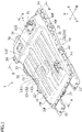
- a battery pack 1 has a flat shape overall, except for an elevated portion 12 in a rear portion as shown in Figure 1 , based on the assumption of being mounted under the floor of a vehicle.
- front and rear mean a front side and a rear side in a vehicle longitudinal direction FR respectively
- left and right mean a left side and a right side in a vehicle width direction W when oriented to a front side F in the vehicle longitudinal direction respectively
- up” and “down” correspond to an upper side and a lower side in a vehicle height direction H, respectively, unless otherwise stated.
- the battery pack 1 is provided with a plurality of battery modules 31, 32 inside a battery case composed of an upper case 10 and a lower case 20.
- Each of the battery modules 31, 32 is obtained through modularization by retaining a plurality of secondary battery cells (e.g., lithium-ion secondary battery) connected to one another in series, in a laminated state in a box-shaped or frame-shaped inner case.
- secondary battery cells e.g., lithium-ion secondary battery
- the upper case 10 and the lower case 20 are each formed of a press-molded product of a metal having favorable thermal conductive characteristics such as steel, stainless steel or aluminum alloy, in a shell-like shape or a tray-like shape, and function as members for heat dissipation to the outside in their own right.
- a metal having favorable thermal conductive characteristics such as steel, stainless steel or aluminum alloy
- a ridge portion 13 extending in the vehicle longitudinal direction FR is formed at the center in the vehicle width direction W, and on each of left and right sides thereof, three subridge portions 15 (bead portions 151, 152, 153) extending in parallel with the vehicle longitudinal direction FR are formed, as shown in Figure 1 .
- a joining portion 14 with the ridge portion 13 in an inclined face 122 on a front side of the elevated portion 12 is formed in a funnel shape rising and expanding toward the elevated portion 12.
- the ridge portion 13 and the subridge portions 15 described above are a reinforcing structure (reinforcing bead portion) for increasing a surface rigidity of the upper face 11 of the upper case 10 and, at the same time, constitutive elements of the cooling structure forming a channel for circulating air (returning channel) inside the upper case 10, as described later.
- the ridge portion 13 is formed such that a protrusion height of a rear side portion is greater than that of a front side portion in the vehicle longitudinal direction FR, or is formed such that the protrusion height of the ridge portion 13 increases toward the elevated portion 12.
- the upper face 11 of the upper case 10 is formed to be substantially flat as a whole, although it has the ridge portion 13 and the subridge portions 15 described above, whereas the elevated portion 12 elevated above is formed on the rear portion of the upper case 10 so as to be accommodated in a lower space of a kick-up portion under a rear seat of the vehicle.
- An inner space expanded to an upper side by the elevated portion 12 is an installation space for a blower duct 4 and a blower fan 5 constituting the cooling system, and at the same time, also a heat dissipation space spaced apart from the battery modules 31, 32, as described later.
- the battery pack 1 is configured such that a water proofing property and a hermetic property are ensured, by integrating a flange portion 20f around the lower case 20 and a flange portion 10f of the upper case 10 through joining with a bolt or the like via a sealing material 20c, in a state in which: the battery modules 31, 32 and control devices thereof are accommodated in the lower case 20; constitutive members such as the blower duct 4 and the blower fan 5 constituting the cooling system are installed; and necessary wiring is done.
- a support frame 25 functioning as a supporting frame for the battery pack 1 is fixed onto a lower face of the lower case 20.
- the support frame 25 is configured in a ladder-like shape with a pair of left and right side frames 250 and a plurality of cross frames 251, 252, 253, 254, 255 extending in the vehicle width direction W therebetween and being rigidly joined, as shown in Figure 4 .
- the battery pack 1 is provided with four attachment brackets 21, 22, 23, 24 on each of left and right sides, as attachment portions with respect to the vehicle body.
- the attachment brackets 22, 23, 24, except for the frontmost portion are constituted of an upper bracket joined to the flange portion 10f of the upper case 10 of the battery pack 1 and a lower bracket joined to the flange portion 20f of the lower case 20.
- the battery pack 1 is fixed to the vehicle body through tightening of a bolt, which is inserted from below into a bolt hole of each of the attachment brackets 21, 22, 23, 24, to a weld nut in an attachment portion on the vehicle body side.
- a high voltage connector 33 for input and output of electric power with respect to a driving motor of the vehicle is provided on a front end face of the lower case 20, and a high voltage connector 36 for charging is provided on a rear face of the upper case 10 (elevated portion 12).
- a service plug 34 for interrupting electric power of the battery modules 31, 32 upon inspection or in case of emergency is provided on the upper face 11 of the upper case 10, and a control connector 35 is provided on an upper face 121 of the elevated portion 12 of the upper case 10.
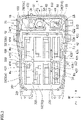
- four battery modules 32 (32a, 32j) are arranged in lateral alignment in the frontmost portion with gaps 320, 322 between one another, while respective longitudinal directions thereof correspond to the vehicle longitudinal direction FR, and on a rear side thereof, which is an intermediate portion of the battery pack 1, four battery modules 32 (32b) are arranged in lateral alignment in a similar arrangement while respective longitudinal directions thereof correspond to the vehicle longitudinal direction FR, as shown in Figure 2 and Figure 3 .
- the module 32j which is second from the right in the frontmost portion, is configured as a junction box provided with a relay circuit that supplies and interrupts electric power to the high voltage connector 33 and the like; however, the module 32j may be configured as a battery module by, for example, consolidating this function into a junction box 38 in the elevated portion 12, and is explained as the battery module 32 for convenience.
- four battery modules 31 are provided in parallel with gaps 310, 312 between one another while respective longitudinal directions thereof correspond to the vehicle width direction W, with a gap 330 with respect to the battery module 32b in the intermediate portion.
- two battery modules 31d on the left side have a smaller number of sets of secondary battery cells than other battery modules, and are configured as half-sized modules having shorter module lengths in the longitudinal direction.
- Each of the battery modules 31, 32 is fixed to reinforcing frames 26, 27, 28 provided on an inner bottom portion of the lower case 20, as shown in Figure 4 and Figure 5 .
- the battery module 32 in the frontmost portion and the intermediate portion is fixed, at both front and rear end portions thereof in the longitudinal direction, with a bolt onto the reinforcing frame 26 extending in the vehicle width direction W provided at three positions to be spaced apart frontward and rearward from the frontmost portion to the intermediate portion of the inner bottom portion of the lower case 20 as shown in Figure 4
- the four battery modules 31 in the rear portion are fixed, at both left and right end portions thereof in the longitudinal direction, with a bolt onto the reinforcing frames 27, 28 extending in the vehicle longitudinal direction FR provided to be spaced apart in both side portions and the intermediate portion in the rear portion of the inner bottom portion of the lower case 20 as shown in Figure 5 .
- the four battery modules 31 (31c, 31d) in the rear portion of the battery pack 1 may be collectively referred to as a first battery module group 31, and the eight battery modules 32 (32a, 32b) in the frontmost portion and the intermediate portion of the battery pack 1 described above may be collectively referred to as a second battery module group 32.
- a support plate 17 for installing the blower duct 4 and the blower fan 5 constituting the cooling system is provided on an upper side of the four battery modules 31 arranged in the rear portion of the battery pack 1.
- the support plate 17 is fixed onto the reinforcing frame 27 via a leg portion 18, on both sides thereof in the vehicle width direction.
- the leg portion 18 is formed of an inverted-U shaped member obtained by bending downward both ends of a frame material extending in the vehicle width direction W along the lower face of the support plate 17, and is fixed to the reinforcing frame 27 in respective lower end portions (flange portions) with a bolt.
- the support plate 17 is provided to extend at substantially the same height as the upper face 11 of the upper case 10 with an interval from the upper face of the battery module 31, to partially partition the inner space of the elevated portion 12 of the upper case 10 except for a peripheral portion thereof, with respect to the battery module 31 side in the lower portion, and has intervals from a side face and a rear face of the elevated portion 12.
- the blower fan 5 is installed in a substantially central portion in the vehicle width direction W of the support plate 17.
- a control device 37 for carrying out charging-and-discharging management, cell balance control and the like of the battery is installed on the right side of the blower fan 5
- the junction box 38 for the high voltage connector 36 is installed on the left side of the blower fan 5
- the blower duct 4 (second branch duct portion 42) is installed.
- a centrifugal fan (sirocco fan or turbofan) can be suitably used as the blower fan 5, which is fixed with a bolt onto the support plate 17 such that a rotational axis direction corresponds to the vehicle height direction H and an inlet 50 is positioned in an upper portion of a fan case.
- a sirocco fan in which a motor is arranged inside a fan hub, a motor housing is prevented from protruding to a lower side and a sufficient air channel is secured on an upper side of the inlet 50.
- the blower duct 4 includes: a proximal portion 40 extending frontward from a discharge port 54 of the blower fan 5; a first branch duct portion 41 extending to the lower side from a communication portion 410 on a bottom portion of a substantially intermediate portion of the proximal portion 40 through an opening 70 on the support plate 17 as shown in Figure 5 and Figure 6 ; and the second branch duct portion 42 connected to a front end portion of the proximal portion 40 as shown in Figure 2 and Figure 3 .
- the first branch duct portion 41 is communicatively connected from the intermediate portions (310, 312) in the vehicle longitudinal direction FR and the vehicle width direction W of the four battery modules 31c, 31d of the first battery module group 31, to a pair of first outlets 417, 418 opened in both left and right direction toward the respective gaps 310, 310 of the battery modules 31c, 31d, as shown in Figure 3 and Figure 5 .
- the first branch duct portion 41 is constituted of a member different from the proximal portion 40, and is not directly connected to the proximal portion 40, as shown in Figure 6 .
- the first branch duct portion 41 is provided with a thick-walled portion 41e in a lower end portion 41b thereof, and in a state in which the lower end portion 41b (thick-walled portion 41e) is fitted into the gap 310 of the battery modules 31, 31, an upper end portion 41a, oriented toward the communication portion 410, comes into contact with a lower face of a periphery of the opening 70 on the support plate 17 through an elastic sealing member, to be held between the support plate 17 and the reinforcing frame 28.
- the thick-walled portion 41e may be either a rib provided to protrude from a lower end portion 41b of the first branch duct portion 41, or a spacer constituted of a member different from the lower end portion 41b.
- Such attachment of the first branch duct portion 41 is done by, after completion of attachment and wiring of the four battery modules 31c, 31d on the lower side of the support plate 17: inserting the first branch duct portion 41 from an upper side into the gap of the battery modules 31c, 31d; holding the lower end portion 41b (thick-walled portion 41e) by the side faces of the battery modules 31, 31 and the upper face of the reinforcing frame 28 for temporary fixation; and, in such a temporarily fixed state, attaching the support plate 17 on an upper side thereof, whereby the first branch duct portion 41 is bound from both upper and lower sides by the support plate 17 and the reinforcing frame 28 via the elastic sealing member.
- the proximal portion 40 of the blower duct 4 is fixed, together with the blower fan 5, onto the upper face of the support plate 17, and a lower face of a periphery of the communication portion 410 comes into contact with an upper face of the periphery of the opening 70 of the support plate 17 via the elastic sealing member, whereby an air-blow channel of the first branching duct 41 is formed from the proximal portion 40 to the first outlets 417, 418 via the communication portion 410.
- the second branch duct portion 42 includes, as shown in Figure 2 and Figure 3 : an upper stream portion (first section) 421 extending from the front end portion of the proximal portion 40 to both sides in the vehicle width direction W along the front edge portion of the support plate 17; an upper stream portion (second section) 422 leading to a first bent portion 423 adjacent to the side portion of the battery case 1; a lower stream portion (first section) 424 extending from the first bent portion 423 to a lower front side in the vehicle longitudinal direction; and a lower stream portion (second section) 426 being bent at a second bent portion 425 on a front side thereof and extending to a central side in the vehicle width direction W.
- the lower stream portion (second section) 426 is communicatively connected from the intermediate portions (320, 322) in the vehicle longitudinal direction FR and the vehicle width direction W of the four battery modules 32a, 32b on the left and right sides of the second battery module group 32, to a pair of second outlets 427, 428 opened respectively on a front side and a rear side toward the respective gaps 320 of the battery modules 32a, 32b.
- the upper stream portions 421, 422 of the second branch duct portion 42 are fixed onto the support plate 17 in a plurality of attachment portions in respective lower front portions of the second sections 422 on the left and right sides and the like, by means of a fastening member or the like.
- the lower stream portions 424, 426 of the second branch duct portion 42 are fixed onto the inner bottom portion of the lower case 20 in a plurality of attachment portions in a side portion of the first section 424 and the like, by means of a fastening member or the like.
- air in the elevated portion 12 is drawn from the inlet 50 through activation of the blower fan 5 to generate:
- the first cooling air Fc, Fd flow from the intermediate portion of the four battery modules 31c, 31d of the first battery module group 31, to each of left and right sides along the respective gaps 310, 310 in the vehicle width direction W of the battery modules 31c, 31d, during which each of the battery modules 31c, 31d is cooled through heat exchange with each of the battery modules 31c, 31d.
- the air heated by the heat exchange with each of the battery modules 31c, 31d rises from a gap portion on both left and right sides in the battery pack 1 as shown by arrows Fc1, Fd1 in Figure 5 ; is collected in the elevated portion 12, which is slightly negative in pressure due to the drawing of the blower fan 5, on the upper side of the support plate 17; dissipates heat through heat exchange with the lower case 20 and the upper case 10 during a process of flowing from side wall portions of the lower case 20 and the elevated portion 12 along a ceiling portion of the elevated portion 12; and is drawn by the inlet 50 of the blower fan 5 as shown by arrows Fc2, Fd2.
- the second cooling air Fa, Fb flow from the intermediate portion of the four battery modules 32a, 32b on the left and right sides of the second battery module group 32, to each of front and rear sides along the respective gaps 320, 320 in the vehicle longitudinal direction FR of the battery modules 32a, 32b, during which each of the battery modules 32a, 32b is cooled through heat exchange with each of the battery modules 32a, 32b.
- the air heated by the heat exchange with each battery module 32a in the frontmost portion rises in a front portion in the battery pack 1 as shown by an arrow Fa1 in Figure 4 ; dissipates heat through heat exchange with the upper case 10 along ceiling portions (11, 13) of the upper case 10, and flows to a rear side toward the elevated portion 12, which is slightly negative in pressure due to the drawing of the blower fan 5.
- the air heated by the heat exchange with each battery module 32b in the intermediate portion also flows to the rear side as shown by arrows Fb1, Fb2 while dissipating heat through heat exchange with the upper case 10, is collected in the elevated portion 12, and is drawn by the inlet 50 of the blower fan 5.
- an inside (negative pressure zone) of the elevated portion 12 of the battery pack 1 is separated by the support plate 17 from a lower side except for a peripheral portion, and is slightly negative in pressure due to the blower fan 5 (inlet 50) being installed, to generate air flows Fb2, Fc2, Fd2 directed to the drawing opening 50 along the ceiling portion.
- the rear portion (first positive pressure zone) of the battery pack 1 in which the first battery module group 31 is installed and the cooling air Fc, Fd are blown from the first outlets 417, 418 of the blower duct 4 to each of left and right sides
- the front portion and the intermediate portion (second positive pressure zone) of the battery pack 1 in which the second battery module group 32 is installed and the second cooling air Fa, Fb are blown from the second outlets 427, 428 to each of front and rear sides are slightly positive in pressure.
- a cross sectional area of an air channel oriented in the vehicle longitudinal direction FR is secured between the upper face of the second battery module group 32 and the inner ceiling face of the upper case 10, whereby formation of the air flow Fb1 flowing to the rear side along an inner ceiling portion of the upper case 10 is promoted.
- the blower fan 5 being arranged at a substantial center in the vehicle width direction W of the elevated portion 12, there is an advantage of promoting the air circulation from the ridge portion 13, which is a main air channel having the greatest cross section of air channel, to the inlet 50 of the blower fan 5.
- the configuration in which the ridge portion 13 is formed such that the protrusion height increases toward the elevated portion 12 and the configuration in which the joining portion 14 between the ridge portion 13 and the inclined face 122 on the front side of the elevated portion 12 is formed in a funnel shape rising and expanding toward the elevated portion 12 further promote the aforementioned air circulation.
- the ridge portion 13 and the subridge portion 15 in the vehicle longitudinal direction FR formed on the upper face 11 of the upper case 10 increase a heat exchange area on the upper face 11 of the upper case 10, whereby increase in heat exchange efficiency and heat dissipation efficiency can also be expected.
- the present invention may also be carried out in a mode in which the elevated portion 12 is provided in the front portion or the intermediate portion in the vehicle longitudinal direction.
Landscapes
- Engineering & Computer Science (AREA)
- Chemical & Material Sciences (AREA)
- Chemical Kinetics & Catalysis (AREA)
- Electrochemistry (AREA)
- General Chemical & Material Sciences (AREA)
- Manufacturing & Machinery (AREA)
- Aviation & Aerospace Engineering (AREA)
- Combustion & Propulsion (AREA)
- Transportation (AREA)
- Mechanical Engineering (AREA)
- Secondary Cells (AREA)
- Battery Mounting, Suspending (AREA)
Abstract
[Problem to be Solved] To improve blowing circulation efficiency inside the sealed type battery back, to thereby achieve a simplification of the structure, homogenization of the temperature distribution inside the battery pack, and a desired cooling effect.
[Solution] A cooling structure for a battery pack (1) comprising a plurality of battery modules (31, 32) inside a battery case (10, 20), in which: the battery case is formed of a thermally conductive material as a heat dissipation member; the plurality of battery modules are fixedly arranged inside the battery case with a gap (310, 312, 320, 322, 330) between one another; the battery case comprises thereinside a blower fan (5) arranged on an upper side in a vehicle height direction with respect to the plurality of battery modules, and a blower duct (4; 41, 42) for pressure-feeding air sent out from the blower fan to at least one outlet (417, 418, 427, 428) positioned in the middle of the plurality of battery modules in a vehicle longitudinal direction and a vehicle width direction; and the cooling structure is configured such that the air (Fa, Fb, Fc, Fd) blown from the outlet passes through the gap in the plurality of battery modules and a gap between the plurality of battery modules and an inner face of the battery case, to be circulated to the blower fan.
Description
- The present invention relates to a cooling structure for a battery pack to be mounted in a vehicle.
- A battery pack to be mounted in a vehicle, for example a battery pack for an electric vehicle, is configured by arranging a plurality of modules constituted of a plurality of secondary batteries inside a flat case, and is arranged in a floor portion of a vehicle body or under a floor, for the purpose of providing a larger capacity while securing a vehicle interior space and a luggage compartment space. Since the secondary battery generates heat during charging and discharging, the battery pack is provided with a cooling structure.
- For a cooling structure for a battery pack, an open type that introduces outside air, a sealed type that employs a heat pump, and the like are known; however, the former has a problem regarding penetration of rainwater and dust, while the latter requires a compressor and a heat dissipator provided outside the battery pack (see Patent Literature 1), thus preventing the battery pack from constituting a cooling system by itself, leading to complication of the system and to a problem of condensed water generated in an evaporator provided inside.
- [Patent Literature 1]
JP 2011-011632 A - In view of this, a method of providing a blower fan inside the sealed type battery pack to make the temperature distribution uniform inside the battery pack and to improve efficiency of heat dissipation from a battery case as a heat dissipation member to the outside is being reviewed.
- The present invention has been made in view of the aforementioned circumstances, and an objective of the present invention is to improve air-blowing circulation efficiency inside the battery back, and to achieve simplification of the structure, homogenization of the temperature distribution inside the battery pack, and a desired cooling effect.
- In order to solve the aforementioned problem, the present invention provides a cooling structure for a battery pack comprising a plurality of battery modules inside a substantially sealed battery case, wherein:
- the battery case is formed of a thermally conductive material as a heat dissipation member;
- the plurality of battery modules are fixedly arranged inside the battery case with a gap between one another;
- the battery case comprises thereinside a blower fan arranged on an upper side in a vehicle height direction with respect to the plurality of battery modules, and a blower duct for pressure-feeding air sent out from the blower fan to at least one outlet positioned in the middle of the plurality of battery modules in a vehicle longitudinal direction and a vehicle width direction; and
- the cooling structure is configured such that the air blown from the outlet passes through the gap in the plurality of battery modules and a gap between the plurality of battery modules and an inner face of the battery case, to be circulated to the blower fan.
- Due to configuring as described above, in the cooling structure for a battery pack according to the present invention, the battery module is cooled through heat exchange between air blown to an intermediate portion of the battery module and the battery module, while the air raised in temperature moves to an upper side and is circulated along an upper face (inner face) of the battery case to the blower fan, whereby heat dissipation to the outside through heat exchange with the upper face of the battery case is promoted, air circulation efficiency inside the battery pack is improved, and homogenization of the temperature distribution of the battery module and cooling effect are achieved while preventing the structure from being complex.
-
- [
Figure 1] Figure 1 is a perspective view showing appearance of a battery pack. - [
Figure 2] Figure 2 is a perspective view showing an inside of the battery pack. - [
Figure 3] Figure 3 is a plan view showing the inside of the battery pack. - [
Figure 4] Figure 4 is an A-A cross-sectional view ofFigure 1 . - [
Figure 5] Figure 5 is a B-B cross-sectional view ofFigure 1 . - [
Figure 6] Figure 6 is an enlarged cross-sectional view of a major part ofFigure 4 . - Hereinafter, an embodiment of the present invention is described in detail with reference to the drawings.
- A
battery pack 1 according to an embodiment of the present invention has a flat shape overall, except for an elevatedportion 12 in a rear portion as shown inFigure 1 , based on the assumption of being mounted under the floor of a vehicle. Note that, in the following description, "front" and "rear" mean a front side and a rear side in a vehicle longitudinal direction FR respectively, "left" and "right" mean a left side and a right side in a vehicle width direction W when oriented to a front side F in the vehicle longitudinal direction respectively, and "up" and "down" correspond to an upper side and a lower side in a vehicle height direction H, respectively, unless otherwise stated. - As shown in
Figure 1 to Figure 5 , thebattery pack 1 is provided with a plurality ofbattery modules upper case 10 and alower case 20. Each of thebattery modules - The
upper case 10 and thelower case 20 are each formed of a press-molded product of a metal having favorable thermal conductive characteristics such as steel, stainless steel or aluminum alloy, in a shell-like shape or a tray-like shape, and function as members for heat dissipation to the outside in their own right. - In the
upper case 10 constituting an upper part of thebattery pack 1, on anupper face 11 from a front portion to a rear portion in the vehicle longitudinal direction thereof, aridge portion 13 extending in the vehicle longitudinal direction FR is formed at the center in the vehicle width direction W, and on each of left and right sides thereof, three subridge portions 15 (bead portions 151, 152, 153) extending in parallel with the vehicle longitudinal direction FR are formed, as shown inFigure 1 . In addition, a joiningportion 14 with theridge portion 13 in aninclined face 122 on a front side of the elevatedportion 12 is formed in a funnel shape rising and expanding toward the elevatedportion 12. - The
ridge portion 13 and the subridge portions 15 described above are a reinforcing structure (reinforcing bead portion) for increasing a surface rigidity of theupper face 11 of theupper case 10 and, at the same time, constitutive elements of the cooling structure forming a channel for circulating air (returning channel) inside theupper case 10, as described later. - Note that it is preferable that the
ridge portion 13 is formed such that a protrusion height of a rear side portion is greater than that of a front side portion in the vehicle longitudinal direction FR, or is formed such that the protrusion height of theridge portion 13 increases toward theelevated portion 12. - The
upper face 11 of theupper case 10 is formed to be substantially flat as a whole, although it has theridge portion 13 and the subridge portions 15 described above, whereas theelevated portion 12 elevated above is formed on the rear portion of theupper case 10 so as to be accommodated in a lower space of a kick-up portion under a rear seat of the vehicle. An inner space expanded to an upper side by the elevatedportion 12 is an installation space for ablower duct 4 and ablower fan 5 constituting the cooling system, and at the same time, also a heat dissipation space spaced apart from thebattery modules - The
battery pack 1 is configured such that a water proofing property and a hermetic property are ensured, by integrating aflange portion 20f around thelower case 20 and aflange portion 10f of theupper case 10 through joining with a bolt or the like via a sealingmaterial 20c, in a state in which: thebattery modules lower case 20; constitutive members such as theblower duct 4 and theblower fan 5 constituting the cooling system are installed; and necessary wiring is done. - A
support frame 25 functioning as a supporting frame for thebattery pack 1 is fixed onto a lower face of thelower case 20. Thesupport frame 25 is configured in a ladder-like shape with a pair of left andright side frames 250 and a plurality ofcross frames Figure 4 . - The
battery pack 1 is provided with fourattachment brackets attachment brackets flange portion 10f of theupper case 10 of thebattery pack 1 and a lower bracket joined to theflange portion 20f of thelower case 20. Thebattery pack 1 is fixed to the vehicle body through tightening of a bolt, which is inserted from below into a bolt hole of each of theattachment brackets - Note that, in the
battery pack 1, ahigh voltage connector 33 for input and output of electric power with respect to a driving motor of the vehicle is provided on a front end face of thelower case 20, and ahigh voltage connector 36 for charging is provided on a rear face of the upper case 10 (elevated portion 12). In addition, aservice plug 34 for interrupting electric power of thebattery modules upper face 11 of theupper case 10, and acontrol connector 35 is provided on anupper face 121 of the elevatedportion 12 of theupper case 10. - Inside the
battery pack 1, four battery modules 32 (32a, 32j) are arranged in lateral alignment in the frontmost portion withgaps battery pack 1, four battery modules 32 (32b) are arranged in lateral alignment in a similar arrangement while respective longitudinal directions thereof correspond to the vehicle longitudinal direction FR, as shown inFigure 2 andFigure 3 . - In the illustrated example, the
module 32j, which is second from the right in the frontmost portion, is configured as a junction box provided with a relay circuit that supplies and interrupts electric power to thehigh voltage connector 33 and the like; however, themodule 32j may be configured as a battery module by, for example, consolidating this function into ajunction box 38 in theelevated portion 12, and is explained as thebattery module 32 for convenience. - In a rear portion of an inside of the
battery pack 1, as shown by a dashed line inFigure 3 , four battery modules 31 (31c, 31d) are provided in parallel withgaps gap 330 with respect to thebattery module 32b in the intermediate portion. Among these, twobattery modules 31d on the left side have a smaller number of sets of secondary battery cells than other battery modules, and are configured as half-sized modules having shorter module lengths in the longitudinal direction. - Each of the
battery modules frames lower case 20, as shown inFigure 4 andFigure 5 . - In other words, the
battery module 32 in the frontmost portion and the intermediate portion is fixed, at both front and rear end portions thereof in the longitudinal direction, with a bolt onto the reinforcingframe 26 extending in the vehicle width direction W provided at three positions to be spaced apart frontward and rearward from the frontmost portion to the intermediate portion of the inner bottom portion of thelower case 20 as shown inFigure 4 , and the fourbattery modules 31 in the rear portion are fixed, at both left and right end portions thereof in the longitudinal direction, with a bolt onto thereinforcing frames lower case 20 as shown inFigure 5 . - Note that, in the following description, the four battery modules 31 (31c, 31d) in the rear portion of the
battery pack 1 may be collectively referred to as a firstbattery module group 31, and the eight battery modules 32 (32a, 32b) in the frontmost portion and the intermediate portion of thebattery pack 1 described above may be collectively referred to as a secondbattery module group 32. - As shown in
Figure 2 to Figure 5 , asupport plate 17 for installing theblower duct 4 and theblower fan 5 constituting the cooling system is provided on an upper side of the fourbattery modules 31 arranged in the rear portion of thebattery pack 1. - The
support plate 17 is fixed onto the reinforcingframe 27 via aleg portion 18, on both sides thereof in the vehicle width direction. Theleg portion 18 is formed of an inverted-U shaped member obtained by bending downward both ends of a frame material extending in the vehicle width direction W along the lower face of thesupport plate 17, and is fixed to the reinforcingframe 27 in respective lower end portions (flange portions) with a bolt. - The
support plate 17 is provided to extend at substantially the same height as theupper face 11 of theupper case 10 with an interval from the upper face of thebattery module 31, to partially partition the inner space of theelevated portion 12 of theupper case 10 except for a peripheral portion thereof, with respect to thebattery module 31 side in the lower portion, and has intervals from a side face and a rear face of theelevated portion 12. - The
blower fan 5 is installed in a substantially central portion in the vehicle width direction W of thesupport plate 17. In addition, acontrol device 37 for carrying out charging-and-discharging management, cell balance control and the like of the battery is installed on the right side of theblower fan 5, thejunction box 38 for thehigh voltage connector 36 is installed on the left side of theblower fan 5, and, along a front edge portion of thesupport plate 17 on a front side thereof, the blower duct 4 (second branch duct portion 42) is installed. - A centrifugal fan (sirocco fan or turbofan) can be suitably used as the
blower fan 5, which is fixed with a bolt onto thesupport plate 17 such that a rotational axis direction corresponds to the vehicle height direction H and aninlet 50 is positioned in an upper portion of a fan case. In the illustrated example, by employing a sirocco fan in which a motor is arranged inside a fan hub, a motor housing is prevented from protruding to a lower side and a sufficient air channel is secured on an upper side of theinlet 50. - The
blower duct 4 includes: aproximal portion 40 extending frontward from adischarge port 54 of theblower fan 5; a firstbranch duct portion 41 extending to the lower side from acommunication portion 410 on a bottom portion of a substantially intermediate portion of theproximal portion 40 through anopening 70 on thesupport plate 17 as shown inFigure 5 andFigure 6 ; and the secondbranch duct portion 42 connected to a front end portion of theproximal portion 40 as shown inFigure 2 andFigure 3 . - The first
branch duct portion 41 is communicatively connected from the intermediate portions (310, 312) in the vehicle longitudinal direction FR and the vehicle width direction W of the fourbattery modules battery module group 31, to a pair offirst outlets respective gaps battery modules Figure 3 andFigure 5 . - The first
branch duct portion 41 is constituted of a member different from theproximal portion 40, and is not directly connected to theproximal portion 40, as shown inFigure 6 . In other words, the firstbranch duct portion 41 is provided with a thick-walled portion 41e in alower end portion 41b thereof, and in a state in which thelower end portion 41b (thick-walled portion 41e) is fitted into thegap 310 of thebattery modules communication portion 410, comes into contact with a lower face of a periphery of theopening 70 on thesupport plate 17 through an elastic sealing member, to be held between thesupport plate 17 and the reinforcingframe 28. The thick-walled portion 41e may be either a rib provided to protrude from alower end portion 41b of the firstbranch duct portion 41, or a spacer constituted of a member different from thelower end portion 41b. - Such attachment of the first
branch duct portion 41 is done by, after completion of attachment and wiring of the fourbattery modules branch duct portion 41 from an upper side into the gap of thebattery modules lower end portion 41b (thick-walled portion 41e) by the side faces of thebattery modules frame 28 for temporary fixation; and, in such a temporarily fixed state, attaching thesupport plate 17 on an upper side thereof, whereby the firstbranch duct portion 41 is bound from both upper and lower sides by thesupport plate 17 and the reinforcingframe 28 via the elastic sealing member. - Thereafter, the
proximal portion 40 of theblower duct 4 is fixed, together with theblower fan 5, onto the upper face of thesupport plate 17, and a lower face of a periphery of thecommunication portion 410 comes into contact with an upper face of the periphery of theopening 70 of thesupport plate 17 via the elastic sealing member, whereby an air-blow channel of the first branchingduct 41 is formed from theproximal portion 40 to thefirst outlets communication portion 410. - The second
branch duct portion 42 includes, as shown inFigure 2 andFigure 3 : an upper stream portion (first section) 421 extending from the front end portion of theproximal portion 40 to both sides in the vehicle width direction W along the front edge portion of thesupport plate 17; an upper stream portion (second section) 422 leading to a firstbent portion 423 adjacent to the side portion of thebattery case 1; a lower stream portion (first section) 424 extending from the firstbent portion 423 to a lower front side in the vehicle longitudinal direction; and a lower stream portion (second section) 426 being bent at a secondbent portion 425 on a front side thereof and extending to a central side in the vehicle width direction W. - The lower stream portion (second section) 426 is communicatively connected from the intermediate portions (320, 322) in the vehicle longitudinal direction FR and the vehicle width direction W of the four
battery modules battery module group 32, to a pair ofsecond outlets respective gaps 320 of thebattery modules - The
upper stream portions branch duct portion 42 are fixed onto thesupport plate 17 in a plurality of attachment portions in respective lower front portions of thesecond sections 422 on the left and right sides and the like, by means of a fastening member or the like. Thelower stream portions branch duct portion 42 are fixed onto the inner bottom portion of thelower case 20 in a plurality of attachment portions in a side portion of thefirst section 424 and the like, by means of a fastening member or the like. - In the cooling system configured as described in the foregoing, air in the
elevated portion 12 is drawn from theinlet 50 through activation of theblower fan 5 to generate: - (i) first cooling air Fc, Fd (
Figure 3 ,Figure 5 ,Figure 6 ) being pressure-fed from theproximal portion 40 of theblower duct 4 through the firstbranch duct portion 41 extending to the lower side, and blown from thefirst outlets - (ii) second cooling air Fa, Fb (
Figure 2 to Figure 4 ) being pressure-fed from theproximal portion 40 of theblower duct 4 through theupper stream portions lower stream portions branch duct portion 42, and blown from thesecond outlets - As shown in
Figure 3 andFigure 5 , the first cooling air Fc, Fd flow from the intermediate portion of the fourbattery modules battery module group 31, to each of left and right sides along therespective gaps battery modules battery modules battery modules - The air heated by the heat exchange with each of the
battery modules battery pack 1 as shown by arrows Fc1, Fd1 inFigure 5 ; is collected in theelevated portion 12, which is slightly negative in pressure due to the drawing of theblower fan 5, on the upper side of thesupport plate 17; dissipates heat through heat exchange with thelower case 20 and theupper case 10 during a process of flowing from side wall portions of thelower case 20 and theelevated portion 12 along a ceiling portion of theelevated portion 12; and is drawn by theinlet 50 of theblower fan 5 as shown by arrows Fc2, Fd2. - As shown in
Figure 2 to Figure 4 , the second cooling air Fa, Fb flow from the intermediate portion of the fourbattery modules battery module group 32, to each of front and rear sides along therespective gaps battery modules battery modules battery modules - The air heated by the heat exchange with each
battery module 32a in the frontmost portion rises in a front portion in thebattery pack 1 as shown by an arrow Fa1 inFigure 4 ; dissipates heat through heat exchange with theupper case 10 along ceiling portions (11, 13) of theupper case 10, and flows to a rear side toward theelevated portion 12, which is slightly negative in pressure due to the drawing of theblower fan 5. On the other hand, the air heated by the heat exchange with eachbattery module 32b in the intermediate portion also flows to the rear side as shown by arrows Fb1, Fb2 while dissipating heat through heat exchange with theupper case 10, is collected in theelevated portion 12, and is drawn by theinlet 50 of theblower fan 5. - As described in the foregoing, an inside (negative pressure zone) of the
elevated portion 12 of thebattery pack 1 is separated by thesupport plate 17 from a lower side except for a peripheral portion, and is slightly negative in pressure due to the blower fan 5 (inlet 50) being installed, to generate air flows Fb2, Fc2, Fd2 directed to thedrawing opening 50 along the ceiling portion. - On the other hand, the rear portion (first positive pressure zone) of the
battery pack 1 in which the firstbattery module group 31 is installed and the cooling air Fc, Fd are blown from thefirst outlets blower duct 4 to each of left and right sides, and the front portion and the intermediate portion (second positive pressure zone) of thebattery pack 1 in which the secondbattery module group 32 is installed and the second cooling air Fa, Fb are blown from thesecond outlets - Due to a pressure difference between the negative pressure zone (12) and the first and second positive pressure zones (31, 32) described above, and a rise in temperature of the cooling air through the heat exchange with the first and second
battery module groups upper case 10 and leading to theelevated portion 12 at the relatively highest position is promoted, and consequently, the heat exchange on theupper face 11 of theupper case 10 and theupper face 121 of theelevated portion 12 is promoted, whereby a cooling effect for the first and secondbattery module groups battery module groups - In addition, due to the
ridge portion 13 and the subridge portion 15 in the vehicle longitudinal direction FR formed on theupper face 11 of theupper case 10, a cross sectional area of an air channel oriented in the vehicle longitudinal direction FR is secured between the upper face of the secondbattery module group 32 and the inner ceiling face of theupper case 10, whereby formation of the air flow Fb1 flowing to the rear side along an inner ceiling portion of theupper case 10 is promoted. - Furthermore, due to the
ridge portion 13 being formed in the substantially central portion in the vehicle width direction W, and, in a corresponding manner thereto, theblower fan 5 being arranged at a substantial center in the vehicle width direction W of theelevated portion 12, there is an advantage of promoting the air circulation from theridge portion 13, which is a main air channel having the greatest cross section of air channel, to theinlet 50 of theblower fan 5. - In addition, the configuration in which the
ridge portion 13 is formed such that the protrusion height increases toward theelevated portion 12, and the configuration in which the joiningportion 14 between theridge portion 13 and theinclined face 122 on the front side of theelevated portion 12 is formed in a funnel shape rising and expanding toward theelevated portion 12 further promote the aforementioned air circulation. - Furthermore, the
ridge portion 13 and the subridge portion 15 in the vehicle longitudinal direction FR formed on theupper face 11 of theupper case 10 increase a heat exchange area on theupper face 11 of theupper case 10, whereby increase in heat exchange efficiency and heat dissipation efficiency can also be expected. - Note that, although the case in which the
elevated portion 12 is formed in the rear portion in the vehicle longitudinal direction of thebattery case 1 has been explained in the above embodiment, the present invention may also be carried out in a mode in which theelevated portion 12 is provided in the front portion or the intermediate portion in the vehicle longitudinal direction. - It should be added that, although the embodiment of the present invention has been described above, the present invention is not limited to the above embodiment, and various modifications and changes can be further made within the scope of the present invention.
-
- 1
- Battery pack
- 4
- Blower duct
- 5
- Blower fan
- 10
- Upper case
- 11
- Upper face
- 12
- Elevated portion
- 13
- Ridge portion
- 14
- Joining portion (funnel shape portion)
- 15
- Subridge portion
- 17
- Support plate
- 18
- Leg portion
- 20
- Lower case
- 26, 27, 28
- Reinforcing frame
- 31, 31c, 31d
- Battery module (first battery module group)
- 32, 32a, 32b
- Battery module (second battery module group)
- 40
- Proximal portion
- 41
- First branch duct portion
- 42
- Second branch duct portion
- 50
- Inlet
- 54
- Discharge port
- 70
- Opening
- 310, 312, 320, 322, 330
- Gap
- 410
- Communication portion
- 417, 418
- First outlet
- 421, 422
- Upper stream portion
- 424, 426
- Lower stream portion
- 427, 428
- Second outlet
Claims (7)
- A cooling structure for a battery pack comprising a plurality of battery modules inside a substantially sealed battery case, wherein:the battery case is formed of a thermally conductive material as a heat dissipation member;the plurality of battery modules are fixedly arranged inside the battery case with a gap between one another;the battery case comprises thereinside a blower fan arranged on an upper side in a vehicle height direction with respect to the plurality of battery modules, and a blower duct for pressure-feeding air sent out from the blower fan to at least one outlet positioned in the middle of the plurality of battery modules in a vehicle longitudinal direction and a vehicle width direction, andthe cooling structure is configured such that the air blown from the outlet passes through the gap in the plurality of battery modules and a gap between the plurality of battery modules and an inner face of the battery case, to be circulated to the blower fan.
- The cooling structure for a battery pack according to claim 1, wherein the blower fan is a centrifugal fan of which a rotational axis direction is oriented in the vehicle height direction and having an inlet on an upper portion of a fan case.
- The cooling structure for a battery pack according to claim 1 or 2, wherein:an elevated portion elevated with respect to an upper face of the battery module is formed in a rear portion in the vehicle longitudinal direction of the battery case; andthe blower fan is arranged at a substantial center in the vehicle width direction in an inside of the elevated portion.
- The cooling structure for a battery pack according to claim 3, wherein:the inside of the elevated portion is provided with a support plate extending along an upper face of the battery module, and is partitioned from the battery module side by the support plate at a central portion except for a peripheral portion thereof; andthe blower fan is fixedly arranged on the support plate.
- The cooling structure for a battery pack according to any one of claims 1 to 4, wherein:the plurality of battery modules comprise a first battery module group fixedly arranged in a rear portion in the vehicle longitudinal direction of the battery case with a gap between one another, and a second battery module group fixedly arranged further on a front side in the vehicle longitudinal direction than the first battery module group with a gap between one another; andthe blower duct comprises a first branch duct portion for pressure-feeding the air sent out from the blower fan to a first outlet positioned in the middle of the first battery module group in the vehicle longitudinal direction and the vehicle width direction, and a second branch duct portion for pressure-feeding the air to at least one second outlet positioned in the middle of the second battery module group in the vehicle longitudinal direction and the vehicle width direction.
- The cooling structure for a battery pack according to claim 5, wherein the first branch duct portion extends from a proximal portion of the blower duct extending from a discharge port of the blower fan to the second branch duct portion, downward through the support plate, and is communicatively connected to the first outlet.
- The cooling structure for a battery pack according to claim 5, wherein:the second branch duct portion comprises: an upper stream portion extending, inside the elevated portion, from a proximal portion of the blower duct to both sides in the vehicle width direction, and leading to a first bent portion adjacent to a side portion of the battery case; anda lower stream portion extending from the first bent portion to a lower front side in the vehicle longitudinal direction, being bent toward a central side in the vehicle width direction at a second bent portion, and extending along the gap in the second battery module group to lead to the second outlet.
Applications Claiming Priority (1)
| Application Number | Priority Date | Filing Date | Title |
|---|---|---|---|
| JP2020218227A JP7665982B2 (en) | 2020-12-28 | 2020-12-28 | Battery pack cooling structure |
Publications (1)
| Publication Number | Publication Date |
|---|---|
| EP4020664A1 true EP4020664A1 (en) | 2022-06-29 |
Family
ID=78598833
Family Applications (1)
| Application Number | Title | Priority Date | Filing Date |
|---|---|---|---|
| EP21207558.4A Pending EP4020664A1 (en) | 2020-12-28 | 2021-11-10 | Cooling structure for battery pack |
Country Status (2)
| Country | Link |
|---|---|
| EP (1) | EP4020664A1 (en) |
| JP (1) | JP7665982B2 (en) |
Cited By (5)
| Publication number | Priority date | Publication date | Assignee | Title |
|---|---|---|---|---|
| CN116053657A (en) * | 2023-03-31 | 2023-05-02 | 河南锂动电源有限公司 | New energy automobile low temperature resistant group battery |
| FR3131774A1 (en) * | 2022-01-11 | 2023-07-14 | Valeo Systemes Thermiques | Thermal control device, and charging device comprising a thermal control device |
| CN118173941A (en) * | 2024-03-26 | 2024-06-11 | 东莞市百强电源科技有限公司 | Lithium battery low-temperature protection device and use method thereof |
| CN118610653A (en) * | 2024-07-01 | 2024-09-06 | 晶硕光电科技(山东)有限公司 | A fast heat dissipation type lithium battery |
| CN118819260A (en) * | 2024-09-18 | 2024-10-22 | 陕西亿安通信息技术有限公司 | Computer host heat dissipation system and method |
Families Citing this family (1)
| Publication number | Priority date | Publication date | Assignee | Title |
|---|---|---|---|---|
| JP7576111B2 (en) * | 2023-01-06 | 2024-10-30 | 本田技研工業株式会社 | Duct structure |
Citations (7)
| Publication number | Priority date | Publication date | Assignee | Title |
|---|---|---|---|---|
| JP2011011632A (en) | 2009-07-02 | 2011-01-20 | Nissin Kogyo Co Ltd | Vehicle brake hydraulic pressure controller |
| EP2712005A1 (en) * | 2011-05-17 | 2014-03-26 | Nissan Motor Co., Ltd | Battery pack structure for electric vehicles |
| US20150037632A1 (en) * | 2013-08-01 | 2015-02-05 | Denso Corporation | Battery cooling system |
| EP3076457A1 (en) * | 2015-04-02 | 2016-10-05 | Kubota Corporation | Battery pack and electric work vehicle |
| EP3096390A1 (en) * | 2015-05-21 | 2016-11-23 | Automotive Energy Supply Corporation | Battery pack for vehicle |
| EP3361552A1 (en) * | 2017-02-08 | 2018-08-15 | Denso Corporation | Power source apparatus and work machine having the same |
| US20180241104A1 (en) * | 2015-08-07 | 2018-08-23 | Denso Corporation | Battery pack |
Family Cites Families (6)
| Publication number | Priority date | Publication date | Assignee | Title |
|---|---|---|---|---|
| JP2011060733A (en) | 2009-09-14 | 2011-03-24 | Mitsubishi Motors Corp | Battery device |
| JP5477571B2 (en) | 2009-12-24 | 2014-04-23 | 三菱自動車工業株式会社 | Battery pack cooling structure |
| WO2011111949A2 (en) | 2010-03-08 | 2011-09-15 | (주)브이이엔에스 | Vehicle and method for controlling same |
| JP5892119B2 (en) | 2013-08-01 | 2016-03-23 | 株式会社デンソー | Battery cooling device |
| JP2016081846A (en) | 2014-10-21 | 2016-05-16 | ダイキョーニシカワ株式会社 | Vehicle battery pack |
| JP7020370B2 (en) | 2018-10-30 | 2022-02-16 | トヨタ自動車株式会社 | Battery pack |
-
2020
- 2020-12-28 JP JP2020218227A patent/JP7665982B2/en active Active
-
2021
- 2021-11-10 EP EP21207558.4A patent/EP4020664A1/en active Pending
Patent Citations (7)
| Publication number | Priority date | Publication date | Assignee | Title |
|---|---|---|---|---|
| JP2011011632A (en) | 2009-07-02 | 2011-01-20 | Nissin Kogyo Co Ltd | Vehicle brake hydraulic pressure controller |
| EP2712005A1 (en) * | 2011-05-17 | 2014-03-26 | Nissan Motor Co., Ltd | Battery pack structure for electric vehicles |
| US20150037632A1 (en) * | 2013-08-01 | 2015-02-05 | Denso Corporation | Battery cooling system |
| EP3076457A1 (en) * | 2015-04-02 | 2016-10-05 | Kubota Corporation | Battery pack and electric work vehicle |
| EP3096390A1 (en) * | 2015-05-21 | 2016-11-23 | Automotive Energy Supply Corporation | Battery pack for vehicle |
| US20180241104A1 (en) * | 2015-08-07 | 2018-08-23 | Denso Corporation | Battery pack |
| EP3361552A1 (en) * | 2017-02-08 | 2018-08-15 | Denso Corporation | Power source apparatus and work machine having the same |
Cited By (5)
| Publication number | Priority date | Publication date | Assignee | Title |
|---|---|---|---|---|
| FR3131774A1 (en) * | 2022-01-11 | 2023-07-14 | Valeo Systemes Thermiques | Thermal control device, and charging device comprising a thermal control device |
| CN116053657A (en) * | 2023-03-31 | 2023-05-02 | 河南锂动电源有限公司 | New energy automobile low temperature resistant group battery |
| CN118173941A (en) * | 2024-03-26 | 2024-06-11 | 东莞市百强电源科技有限公司 | Lithium battery low-temperature protection device and use method thereof |
| CN118610653A (en) * | 2024-07-01 | 2024-09-06 | 晶硕光电科技(山东)有限公司 | A fast heat dissipation type lithium battery |
| CN118819260A (en) * | 2024-09-18 | 2024-10-22 | 陕西亿安通信息技术有限公司 | Computer host heat dissipation system and method |
Also Published As
| Publication number | Publication date |
|---|---|
| JP7665982B2 (en) | 2025-04-22 |
| JP2022103534A (en) | 2022-07-08 |
Similar Documents
| Publication | Publication Date | Title |
|---|---|---|
| KR102264771B1 (en) | Battery pack | |
| JP7665982B2 (en) | Battery pack cooling structure | |
| EP4020665A1 (en) | Cooling structure for battery pack | |
| EP4064419A1 (en) | Cooling structure for battery pack | |
| CA2924471C (en) | Battery pack | |
| US8464817B2 (en) | Battery mounting structure of electromotive vehicle | |
| EP4410639A1 (en) | Vehicle body floor assembly for vehicle and vehicle | |
| EP2819236A1 (en) | Battery pack temperature control structure for electric vehicles | |
| EP2819235A1 (en) | Battery pack temperature control structure for electric vehicles | |
| US10297803B2 (en) | Battery assembly | |
| US20120121962A1 (en) | Battery cooling structure | |
| EP3361552B1 (en) | Power source apparatus and work machine having the same | |
| US20240336149A1 (en) | Body-in-white (biw) integrated battery frame | |
| EP4087021A1 (en) | Air-cooled battery pack for electric vehicle | |
| WO2021110246A1 (en) | Supporting structure for receiving battery cells | |
| EP3361551B1 (en) | Power source apparatus and working machine having the same | |
| JP7615672B2 (en) | Battery pack cooling structure | |
| US10807483B2 (en) | Fuel cell vehicle | |
| JP7514447B2 (en) | Battery pack cooling structure | |
| JP5822281B2 (en) | Battery pack for electric vehicles | |
| JP2012106558A (en) | Support structure for battery unit for vehicle | |
| JP2000301954A (en) | Vehicle batteries | |
| JP7627422B2 (en) | Battery pack cooling structure | |
| CN117219912A (en) | An air-cooled battery pack and air-cooled energy storage system | |
| CN220796858U (en) | Air cooling circulation system of battery energy storage cabin |
Legal Events
| Date | Code | Title | Description |
|---|---|---|---|
| PUAI | Public reference made under article 153(3) epc to a published international application that has entered the european phase |
Free format text: ORIGINAL CODE: 0009012 |
|
| STAA | Information on the status of an ep patent application or granted ep patent |
Free format text: STATUS: REQUEST FOR EXAMINATION WAS MADE |
|
| 17P | Request for examination filed |
Effective date: 20211110 |
|
| AK | Designated contracting states |
Kind code of ref document: A1 Designated state(s): AL AT BE BG CH CY CZ DE DK EE ES FI FR GB GR HR HU IE IS IT LI LT LU LV MC MK MT NL NO PL PT RO RS SE SI SK SM TR |
|
| STAA | Information on the status of an ep patent application or granted ep patent |
Free format text: STATUS: EXAMINATION IS IN PROGRESS |
|
| 17Q | First examination report despatched |
Effective date: 20240903 |