EP4020307B1 - Inductive aiming trigger - Google Patents
Inductive aiming trigger Download PDFInfo
- Publication number
- EP4020307B1 EP4020307B1 EP21215412.4A EP21215412A EP4020307B1 EP 4020307 B1 EP4020307 B1 EP 4020307B1 EP 21215412 A EP21215412 A EP 21215412A EP 4020307 B1 EP4020307 B1 EP 4020307B1
- Authority
- EP
- European Patent Office
- Prior art keywords
- trigger
- inductive
- code reader
- aiming
- antenna
- Prior art date
- Legal status (The legal status is an assumption and is not a legal conclusion. Google has not performed a legal analysis and makes no representation as to the accuracy of the status listed.)
- Active
Links
Images




Classifications
-
- G—PHYSICS
- G06—COMPUTING OR CALCULATING; COUNTING
- G06K—GRAPHICAL DATA READING; PRESENTATION OF DATA; RECORD CARRIERS; HANDLING RECORD CARRIERS
- G06K7/00—Methods or arrangements for sensing record carriers, e.g. for reading patterns
- G06K7/10—Methods or arrangements for sensing record carriers, e.g. for reading patterns by electromagnetic radiation, e.g. optical sensing; by corpuscular radiation
- G06K7/10544—Methods or arrangements for sensing record carriers, e.g. for reading patterns by electromagnetic radiation, e.g. optical sensing; by corpuscular radiation by scanning of the records by radiation in the optical part of the electromagnetic spectrum
- G06K7/10821—Methods or arrangements for sensing record carriers, e.g. for reading patterns by electromagnetic radiation, e.g. optical sensing; by corpuscular radiation by scanning of the records by radiation in the optical part of the electromagnetic spectrum further details of bar or optical code scanning devices
- G06K7/10881—Methods or arrangements for sensing record carriers, e.g. for reading patterns by electromagnetic radiation, e.g. optical sensing; by corpuscular radiation by scanning of the records by radiation in the optical part of the electromagnetic spectrum further details of bar or optical code scanning devices constructional details of hand-held scanners
-
- G—PHYSICS
- G06—COMPUTING OR CALCULATING; COUNTING
- G06K—GRAPHICAL DATA READING; PRESENTATION OF DATA; RECORD CARRIERS; HANDLING RECORD CARRIERS
- G06K7/00—Methods or arrangements for sensing record carriers, e.g. for reading patterns
- G06K7/10—Methods or arrangements for sensing record carriers, e.g. for reading patterns by electromagnetic radiation, e.g. optical sensing; by corpuscular radiation
- G06K7/10544—Methods or arrangements for sensing record carriers, e.g. for reading patterns by electromagnetic radiation, e.g. optical sensing; by corpuscular radiation by scanning of the records by radiation in the optical part of the electromagnetic spectrum
- G06K7/10821—Methods or arrangements for sensing record carriers, e.g. for reading patterns by electromagnetic radiation, e.g. optical sensing; by corpuscular radiation by scanning of the records by radiation in the optical part of the electromagnetic spectrum further details of bar or optical code scanning devices
-
- G—PHYSICS
- G06—COMPUTING OR CALCULATING; COUNTING
- G06K—GRAPHICAL DATA READING; PRESENTATION OF DATA; RECORD CARRIERS; HANDLING RECORD CARRIERS
- G06K7/00—Methods or arrangements for sensing record carriers, e.g. for reading patterns
- G06K7/08—Methods or arrangements for sensing record carriers, e.g. for reading patterns by means detecting the change of an electrostatic or magnetic field, e.g. by detecting change of capacitance between electrodes
- G06K7/082—Methods or arrangements for sensing record carriers, e.g. for reading patterns by means detecting the change of an electrostatic or magnetic field, e.g. by detecting change of capacitance between electrodes using inductive or magnetic sensors
- G06K7/083—Methods or arrangements for sensing record carriers, e.g. for reading patterns by means detecting the change of an electrostatic or magnetic field, e.g. by detecting change of capacitance between electrodes using inductive or magnetic sensors inductive
-
- G—PHYSICS
- G06—COMPUTING OR CALCULATING; COUNTING
- G06K—GRAPHICAL DATA READING; PRESENTATION OF DATA; RECORD CARRIERS; HANDLING RECORD CARRIERS
- G06K7/00—Methods or arrangements for sensing record carriers, e.g. for reading patterns
- G06K7/08—Methods or arrangements for sensing record carriers, e.g. for reading patterns by means detecting the change of an electrostatic or magnetic field, e.g. by detecting change of capacitance between electrodes
- G06K7/089—Methods or arrangements for sensing record carriers, e.g. for reading patterns by means detecting the change of an electrostatic or magnetic field, e.g. by detecting change of capacitance between electrodes hand-held scanners
-
- G—PHYSICS
- G06—COMPUTING OR CALCULATING; COUNTING
- G06K—GRAPHICAL DATA READING; PRESENTATION OF DATA; RECORD CARRIERS; HANDLING RECORD CARRIERS
- G06K7/00—Methods or arrangements for sensing record carriers, e.g. for reading patterns
- G06K7/10—Methods or arrangements for sensing record carriers, e.g. for reading patterns by electromagnetic radiation, e.g. optical sensing; by corpuscular radiation
- G06K7/10544—Methods or arrangements for sensing record carriers, e.g. for reading patterns by electromagnetic radiation, e.g. optical sensing; by corpuscular radiation by scanning of the records by radiation in the optical part of the electromagnetic spectrum
- G06K7/10792—Special measures in relation to the object to be scanned
- G06K7/10801—Multidistance reading
- G06K7/10811—Focalisation
-
- G—PHYSICS
- G06—COMPUTING OR CALCULATING; COUNTING
- G06K—GRAPHICAL DATA READING; PRESENTATION OF DATA; RECORD CARRIERS; HANDLING RECORD CARRIERS
- G06K7/00—Methods or arrangements for sensing record carriers, e.g. for reading patterns
- G06K7/10—Methods or arrangements for sensing record carriers, e.g. for reading patterns by electromagnetic radiation, e.g. optical sensing; by corpuscular radiation
- G06K7/14—Methods or arrangements for sensing record carriers, e.g. for reading patterns by electromagnetic radiation, e.g. optical sensing; by corpuscular radiation using light without selection of wavelength, e.g. sensing reflected white light
- G06K7/1404—Methods for optical code recognition
- G06K7/1408—Methods for optical code recognition the method being specifically adapted for the type of code
- G06K7/1417—2D bar codes
-
- G—PHYSICS
- G06—COMPUTING OR CALCULATING; COUNTING
- G06K—GRAPHICAL DATA READING; PRESENTATION OF DATA; RECORD CARRIERS; HANDLING RECORD CARRIERS
- G06K2207/00—Other aspects
- G06K2207/1011—Aiming
-
- G—PHYSICS
- G06—COMPUTING OR CALCULATING; COUNTING
- G06K—GRAPHICAL DATA READING; PRESENTATION OF DATA; RECORD CARRIERS; HANDLING RECORD CARRIERS
- G06K2207/00—Other aspects
- G06K2207/1013—Multi-focal
Definitions
- Handheld barcode readers or code readers are often in the form of a "gun” in which electro-optics are used to perform scanning or imaging machine-readable indicia (e.g., barcodes, QR codes, or other code formats).
- Other mobile barcode readers or portable data terminals are gun shaped by having a mount positioned on a handle with a trigger that causes the mobile barcode reader to perform barcode reading functions in the same or similar manner as an integrated barcode reader.
- the code reader may be configured to perform a pre-trigger aiming function, such as outputting an aiming pattern, such as an illumination in the shape of a frame or corners defining a frame with a central feature, so that the user of the code reader may more easily see where he or she is aiming the reader, thereby reducing time for performing code reading.
- a pre-trigger aiming function such as outputting an aiming pattern, such as an illumination in the shape of a frame or corners defining a frame with a central feature, so that the user of the code reader may more easily see where he or she is aiming the reader, thereby reducing time for performing code reading.
- electro-mechanical switch physically aligned with the trigger plunger and the photocell sensor has some drawbacks, including (i) increased internal dimensions for a housing of the photocell, (ii) need for an additional PCB slot, and (iii) increased complexity of molds to produce a housing and pre-trigger aiming sensing components to incorporate the pre-trigger aiming function.
- drawbacks including (i) increased internal dimensions for a housing of the photocell, (ii) need for an additional PCB slot, and (iii) increased complexity of molds to produce a housing and pre-trigger aiming sensing components to incorporate the pre-trigger aiming function.
- a contactless inductive pre-trigger configuration may be utilized.
- the inductive pre-aiming trigger may be configured within electro- magnetic sensor and conductive element that, when moved by a user moving a trigger of the handheld code reader, is sensed by the electro-magnetic sensor.
- the sensor may sense an inductive change that causes the electronics to initiate a pre-trigger aiming function, such as generating a pre-trigger aiming pattern, to assist a user in imaging a machine-readable indicia.
- a handheld code reader may include a main structure and electro-optics positioned at the main structure.
- the electro-optics may be configured to image or scan machine-readable codes.
- a handle may extend from the main structure, and may be configured to enable a user to grip the handle to operate the code reader.
- Electronics may be configured to cause the electro-optics to perform (i) a pre-trigger aiming function and (ii) a code reading function.
- a trigger may be configured to be pulled toward the handle by the user.
- An antenna may be in electrical communication with the electronics, and be configured to sense an inductive change caused by the user pulling the trigger from a resting position toward a pre-trigger aiming function position.
- a switch may be in electrical communication with the electronics, and be positioned to be activated by the trigger being pulled to a scan position.
- the switch may include a metallic dome portion.
- the antenna may be configured to sense an inductive change when the metallic dome or metallic dome portion is deformed by the trigger.
- the electronics may be further configured to enable a user to set a pre-trigger aiming threshold level, which when crossed by the inductive change, causes the electronics to initiate the pre-trigger aiming function.
- the code reader may further comprise a conductive element positioned on the trigger, and the antenna may be configured to sense a change in location of the conductive element.
- the electronics may be configured to determine a resting-state inductive value when the trigger is in a resting position, and to store the resting-state inductive value as a reference value.
- the electronics may be further configured to:
- One method of operating a code reader may include sensing an inductive change during operation of a trigger of the code reader, and, in response to determining that the inductive change crosses a pre-trigger inductive threshold level, performing a pre-trigger aiming function.
- Sensing an inductive change may include sensing an inductive change in response to an inductive device moving through an electromagnetic field.
- sensing an inductive change may include sensing an inductive change in response to a metallic dome of a dome switch being deformed by a trigger of the code reader.
- the method may further include self-calibrating the code reader by:
- sensing the inductive change may include:
- the method may further include enabling a user to set the pre-trigger aiming threshold level.
- a handheld code reader may include a main structure, a handle extending from the main structure, and a trigger configured to be pulled by a finger of a user holding the handle.
- the code reader may further include a conductive element, an antenna configured to sense an inductive change caused by the trigger moving the conductive element, and electronics in electrical communication with the antenna, the electronics configured to determine when the inductive change is indicative of a user selecting to activate a pre-trigger aiming function.
- the electronics being configured to determine when the inductive change is indicative of the user selecting to activate a pre-trigger aiming function may include sensing when a difference between a resting-state inductive value and an instant inductive value crosses a pre-trigger inductive threshold level.
- the antenna may be a circular antenna positioned at the handle.
- the electronics may be further configured to enable a user to set a pre-trigger aiming threshold level, which when crossed by the inductive change, causes the electronics to initiate the pre-trigger aiming function.
- the conductive element may be positioned on the trigger.
- the code reader may further include a switch positioned to be pressed by the trigger, and the conductive element may be a metal dome on the switch, and the antenna may encircle the switch and be configured to sense the inductive change in response to the metal dome being deformed by the trigger.
- the electronics in response to determining when the inductive change crosses a pre-trigger inductive threshold level, may cause a pre-trigger aiming illumination pattern to be projected from the code reader.
- the code reader 100 includes a main structure 102 with a window 104 via which optics (not shown) are able to scan or image machine-readable indicia (e.g., barcode, QR code, or other machine-readable code).
- the main structure 102 is shown as a housing, but the main structure may alternatively be a holder configured to enable a mobile device, such as a mobile barcode scanner in the shape of a smartphone, for example, to be secured thereby.
- the main structure 102 may alternatively include a flat surface on which a mobile device is placed and secured by sides extending upwards from the flat surface that are shaped to secure the mobile device to the flat surface.
- the handle 106 may be connected to the main housing 102, and be configured to house electronics for performing code reading and pre-trigger aiming functionality, as described further herein.
- a trigger 108 may be positioned near a top portion of the handle 106 just beneath the main body 102, and be configured to enable a user to transition the trigger 108 between a resting position and a read position, where the read position causes the code reader to capture an image of a machine-readable indicia, as further described herein.
- a pre-trigger aiming function may be initiated in response to the trigger causing an inductive change to occur, as further described herein.
- FIG. 2 an illustration of an illustrative pre-trigger aiming illumination pattern 200 that aids a user in imaging a machine-readable indicia is shown.
- the pre-trigger aiming illumination pattern 200 is shown to include first illumination features 202a-202d (collectively 202 ) that define a rectangle shape 204 along with second illumination features 206a-206d (collectively 206 ) defining a square shape 208 located in a center region of the rectangular shape 204.
- pre-trigger aiming illumination patterns may be utilized, such as a plus-sign (+) disposed in a center region of the rectangle shape 204, lines to define outside regions of the rectangle shape 204, or any other shapes that defined corners, edges, or inner portions of a region that the code reader will image during operation of the code reader.
- the pre-trigger illumination pattern 200 may include the rectangle shape 204 or other shape only, inside square shape 208, or other shape only.
- FIGS. 3A and 3B illustrations of scenes 300a and 300b in which a pre-trigger aiming pattern 302 is displayed on a linear code or one-dimensional code 304a, such as a conventional barcode, and a two-dimensional code 304b, such as a QR code, is shown.
- Aiming light source(s) may any illumination source, including LED or laser.
- the pre-trigger aiming pattern 302 may include only center features (e.g., a simple spot, for example) or only perimeter-defining features, or both, as further described herein.
- the pre-trigger aiming pattern 302 may include perimeter-defining illumination features 306 and center feature 308, as provided in FIG. 2 .
- the perimeter-defining illumination features 306 may be used to aid a user imaging the code 304a being read, and the center illumination feature 308 may show that the code reader is aiming centrally at the code 304a.
- the two dimensional code 304b is fully encompassed within the rectangle defined by the perimeter-defining illumination features 306, and the center illumination feature 308 is centrally located on the 2D code.
- a trigger 402 is shown in a resting position or state, and may include a conductive element 404 attached thereto.
- the conductive element 404 may be formed of any material that may be sensed by sensing magnetic field distortion by an inductive sensor. Although the conductive element 404 may be disposed on the trigger 402, alternative positions of the conductive element 404 may be utilized. Moreover, the conductive element 404 may be integrated into another component relative to the inductive sensor.
- a switch 406 may be mounted to a printed circuit board (PCB) 408, configured to be depressed by the trigger 402.
- the switch 406 may be an electromechanical switch or other type of switch that is mechanically activated by the trigger 402.
- the PCB 408 may be positioned within a cavity defined by a handle of the code reader, and define a rigid support for the switch 406 such that the switch 406 has minimal or no compliance relative to the trigger 402 when being operated by a user.
- the code reader may be more robust over time as the amount of force needed to cause the code reader to perform reading functions may remain constant over time a warping or other elastic deformation of the support for the switch 406 is less likely to occur.
- the antenna 410 may be a circular antenna that encircles the switch 406.
- the antenna 410 may include multiple, concentric circular antennas, as shown.
- the antenna 410 may be printed on the PCB 408, and be in electrical communication with processing electronics (see, for example, FIG. 7 ) that are capable of processing signals, in this case magnetic field distortion signals or inductive change signals sensed by the antenna 410.
- processing electronics see, for example, FIG. 7
- the antenna 410 may be formed by circular antennas, it should be understood that alternative antenna shapes may be utilized.
- the antenna 410 may be positioned elsewhere and be capable of sensing an inductive change resulting from a user moving the trigger 402 that causes a conductive element to move.
- an antenna may be positioned on or in the trigger 402 and a conductive element may be positioned in relative position to the trigger 402.
- the antenna 410 may be positioned on or in the main housing of the code reader.
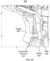
- FIG. 4C an illustration of the trigger portion 400 with the trigger 402 in a read position in which the trigger 402 causes a switch to be activated is shown.
- a trigger plunger or the conductive element 404 may depress the switch 406 mounted to the PCB 408.
- the conductive element 404 moves through a variation of inductance, thereby enabling the antenna 410 to sense an inductive change.
- the inductive sensing may be performed using a high-resolution, high-speed inductive-to-digital converter (see FIG. 7 ).
- the inductive sensing may be designed for a number of different functions and/or applications to be performed by the code reader based on the inductivity measurements. It is possible to detect position, rotation, or motion of an object, such as the trigger 402.
- the converter allows both inductance and impedance to be measured. Featuring a wide inductor-capacitor (LC) sensor frequency range, a broad range of conductive materials of the conductive element 404 may be sensed.
- LC inductor-capacitor
- the dome switch 500 may include a housing 502 and dome 504.
- the dome 504 may be a flexible material, such as a flexible metal, so as to be able to be repetitively deformed without permanently damaging the dome shape.
- the dome 504 may be conductive, and be utilized to be sensed by an inductive sensor, as further described in FIGS. 6A and 6B .
- the switch assembly 600a may include a keycap 602 that includes a dome activator feature or key 604 that protrudes from a bottom surface of the keycap 602 so as to engage a dome switch 605 and depress a metallic dome 606 of the dome switch 605 mounted to a PCB 607.
- the dome activator feature 604 in the non-pressed state, may contact or be slightly above the dome 606, but not deform the dome 606, and in the pressed state, the dome activator feature 604 may deform the dome and cause the dome to be pressed into a contact 608b of contacts 608a-608c so as to activate the switch 605.
- the switch assembly 600a may include the keycap 602 and switch 605 in a common package.
- the keycap 602 may be positioned on a trigger of a code reader and aligned with the dome 606 of the switch 605 so that when the trigger is pulled to an image trigger position, the dome activator feature 604 of the keycap 602 deforms the dome 606, thereby causing a pre-trigger aiming function to be initiated, as described below.
- the dome 606 contacts the contact 608b, to cause a circuit to be completed and an electrical signal to be communicated to a processor to initiate an image capture, for example, by the code reader.
- an inductive change sensor or antenna 610 may be printed on, mounted to, or positioned at a PCB 612 on which the switch 605 is mounted.
- the antenna 610 may be a circular antenna, such as the antenna 410 of FIG. 4B .
- the metal dome 606 of the dome switch 605 may be utilized as the conductive element. That is, as the metal dome 606 is deformed, an inductive change may be sensed by the antenna 610.
- the shape, size, and spacing of the antenna 610 relative to the dome switch 605 may vary depending on the desired sensitivity, which may be a function of an antenna pattern produced by the antenna 610. As understood in the art, different antenna designs may produce different antenna patterns.
- the antenna 610 capable of high-resolution and high-precision measurement of a magnetic field distortion within an antenna pattern (i.e., sensing region)
- the electrical system 700 may include electronics, including a processor 702, which may include a microprocessor, application specific integrated circuit (ASIC), and/or other electronics, configured to sense inductive changes and perform code reading functionality in accordance with the principles described herein.
- An antenna 704 which may be a circular antenna with one or more circular antenna elements, may be configured to sense inductive changes caused by a trigger of the code reader moving a conductive element 706.
- the conductive element 706 may be formed of any conductive material that may be sensed by the antenna 704.
- the antenna 704 may be in electrical communication with an inductance-to-digital (I/D) converter 708, which may be in electrical communication with the processor 702.
- the processor may further be in communication with a switch 710, aiming illuminator 712, imaging illuminator 713, and imager 714.
- the processor 702 may be configured to manage the functional operations of the code reader, including a pre-trigger aiming function and code imaging and decoding function.
- an inductive sense signal 716 may be produced in response to the antenna 704 sensing an inductive level and/or inductive change.
- the inductive sense signal 716 may be an analog signal that is dynamic to represent an inductive change or relative position of a conductive element, a sinusoidal signal in response to sensing the inductive change, or any other analog signal.
- the inductive sense signal 716 may be received and processed by the I/D converter 708.
- the I/D converter 708 may generate an inductive sense digital signal 708 that digitally represents the inductive sense signal 716.
- the processor 702 may receive the inductive sense digital signal 718 and determine an inductive level of the corresponding inductive sense signal 716 to determine whether the inductive level is at a level to initiate a pre-trigger aiming function. In determining whether the inductive level is indicative to initiate the pre-trigger aiming function, a comparison may be made by the processor 702 between the instant inductive level and a baseline inductive level when the trigger, and consequently the conductive element 706, is in a resting state or position.
- the inductive sensing may be passive or active.
- the processor 702 may generate a pre-trigger aiming signal 720 to cause the aiming illuminator 712 to generate a pre-trigger aiming pattern signal 722 within a projection zone 724 to generate a pre-trigger aiming pattern 726.
- the instant inductive level may start at 0.0 Henry (self-calibrated) at a resting state and end at 0.5 Henry at the point when a switch is activated.
- a pre-trigger aiming function threshold level is set at 0.25 Henry (e.g., corresponding to 2mm trigger pull)
- the pre-trigger aiming function may be triggered when the trigger is pulled 2mm, and the inductive level may be 0.25 Henry, which is a difference of 0.25 Henry from the resting state.
- the projection zone 724 may be the same or similar angle as an angle defining a field-of-view 726 of the imager 714 used to capture an image or scan a scene in which a machine-readable indicia or code 730 is positioned. That is, the projection zone 724 is to overlap the scene within the field-of-view 726 of the imager 714.
- the processor 702 may generate an image capture signal 708 to cause the imager 714 to capture an image within the field-of-view 728.
- the processor 702 may generate an imaging illumination signal 736 to cause an imaging illuminator 738 to generate an illumination signal (not shown) that illuminates the code 730 being imaged.
- the illumination signal may have the same or similar field-of-view as the imager 714 such that the code 730 is illuminated.
- the imaging illuminator 738 may be turned to an ON state prior to the imager 714 capturing an image so that the code 730 is illuminated prior to the imager 714 capturing an image of the code 730.
- the imager 714 may generate image data 734 for the processor 702 to process and decode the machine-readable indicia 730, as understood in the art.
- the code reader 700 may further include a user interface 740 in electrical communication with the processor 702.
- the user interface 740 may include an electronic display that is touch sensitive such that a graphical user interface may be displayed for a user to set up ad operate the code reader 700.
- the user interface 740 may include electromechanical components, such as knobs, switches, or otherwise, that enable a user to set parameters, such as a pre-trigger aiming threshold level.
- the user interface 740 may be positioned on the code reader 700, but may also be positioned on an external device.
- Such external positioning of a user interface may be the case in which the code reader 700 is connected wirelessly or with cables to a personal computer or other electronic device to be configured, where the configuration options may be a pre-trigger setting option for setting responsiveness and behavior of the pre-trigger aiming function. Because some code readers do not have a user interface, enabling an external user interface to establish pre-trigger aiming or other settings may be more efficient and less costly than alternative techniques for establishing the pre-trigger aiming or other settings.
- the user interface 740 may enable a user to select a factory setting for the pre-trigger aiming threshold level, which may have multiple selection options (e.g., low, medium, high) or allow for a user to select a level within a range.
- a user may interact with the user interface 740 to select a pre-trigger aiming inductance level 742, which may be communicated from the user interface 740 to the processor 702.
- the code reader 700 may have a factory setting for the pre-trigger aiming threshold level as a default and be selectable or resettable to the factory setting.
- the pre-trigger aiming threshold level may be stored in a non-transitory memory, and accessed during operation of the code reader 700.
- the code reader may be configured with the ability to let the user set the inductive threshold level while pulling the trigger to a desired threshold location (e.g., pull the trigger a desired amount and press a button).
- the processor may store the inductive value measured at the desired trigger location, and thereafter, the reader may use that stored inductive threshold level for determining an inductive change.
- a flow diagram of a process 800 for self-calibrating a code reader to perform a pre-trigger aiming function by using inductive sensing is shown.
- the process 800 may start at step 802, where a determination may be made as to whether a trigger of the code reader in a resting position. If not, then the process may repeat step 802.
- a user may notify the code reader (i.e., a processor of the code reader) via a user interface (e.g., touch screen, mechanical button, or otherwise) that a trigger of the code reader is in a resting position (i.e., not being pulled toward a switch).
- a resting position inductive value may be measured by an inductive sensor.
- the resting position inductive value may be stored in a non-transitory memory for use as a reference value for inductive changes during operation of the code reader.
- the code reader may be configured to self-calibrate in a resting position to set a base inductive value.
- a manufacturer may set the pre-trigger inductive threshold level.
- the self-calibration process may be independent of establishing a pre-trigger threshold level and independent of the pre-trigger threshold level.
- a user may set the pre-trigger inductive threshold level by allowing the user to pull the trigger to a desired position and pressing a button that causes the code reader to store a pre-trigger inductive threshold level.
- Alternative techniques may be utilized to enable the user to configure the pre-trigger threshold.
- the pre-trigger aiming function is to be initiated when the inductive change is greater than the pre-trigger inductive threshold level as offset by the resting inductive value or crosses a pre-trigger inductive value set by the user moving the trigger to a desired location.
- a flow diagram of a process 900 for a user of a code reader to set a pre-trigger threshold level is shown.
- the pre-trigger threshold is configurable by the user.
- the process 900 may start at step 902, where a user moves a trigger to a desired pre-trigger threshold level position.
- a pre-trigger inductive threshold level may be measured by an inductive sensor.
- a user may press a button or hold the trigger at a certain location for a certain time period, such as 3 seconds, if the code reader in a user calibration mode, for example.
- the pre-trigger inductive threshold level may be stored at a threshold level for determining when to initiate a pre-trigger aiming function during normal operation of the code reader.
- a flow diagram of a process 1000 for a code reader to perform a pre-trigger aiming function by using inductive sensing by a code reader is shown.
- the process 1000 may start at step 1002 by sensing an instant inductive value during operation of a trigger of the code reader.
- an inductive change from a resting position of the code reader may be determined. The determination may be performed by previously performing a self-calibration operation as provided in FIG. 8 or a user setting operation as provided in FIG. 9 .
- a determination may be made as to whether an inductive change crosses a pre-trigger inductive threshold level.
- the pre-trigger inductive threshold level may be set to a minimum level that is indicative of a user intentionally moving the trigger by a certain distance (e.g., 3mm move of the trigger).
- the pre-trigger inductive threshold level may be set to a corresponding inductive value that corresponds to a certain distance of movement. It should be understood that the minimum level may be set based on the type of conductive element is being sensed, type of inductive sensor, sensitivity of the inductive sensor, signal-to-noise level of the inductive sensor, resolution of an inductance-to-digital converter, or otherwise.
- step 1006 a determination is made that the inductive change does not cross the pre-trigger inductive threshold level, then the process returns to step 1002. Otherwise, if the inductive change does cross the pre-trigger inductive threshold level, then the process may continue to step 1008, where a pre-trigger aiming function may be performed.
- a pre-trigger aiming function may include generating a pre-trigger aiming signal to display a pre-trigger aiming pattern to assist the user image a machine-readable indicia with the code reader, as previously described herein.
- One embodiment of a process of operating a code reader may include sensing an inductive change during operation of a trigger of the code reader, and in response to determining that the inductive change crosses a pre-trigger inductive threshold level, performing a pre-trigger aiming function.
- the code reader may be self-calibrated by sensing a resting-state inductive value, and storing the resting-state inductive value. Sensing the inductive change may include sensing an instant inductive value, determining a difference inductive value between the instant inductive value and the resting-state inductive value, and in response to the difference inductive value crossing the pre-trigger inductive threshold level, performing the pre-trigger aiming function. Sensing an inductive change may further include sensing and inductive change until a button is pressed to cause the code reader to perform a scan function.
- process flow diagrams are provided merely as illustrative examples and are not intended to require or imply that the steps of the various embodiments must be performed in the order presented. As will be appreciated by one of skill in the art, the steps in the foregoing embodiments may be performed in any order. Words such as “then,” “next,” etc. are not intended to limit the order of the steps; these words are simply used to guide the reader through the description of the methods.
- process flow diagrams may describe the operations as a sequential process, many of the operations may be performed in parallel or concurrently. In addition, the order of the operations may be rearranged.
- a process may correspond to a method, a function, a procedure, a subroutine, a subprogram, etc. When a process corresponds to a function, its termination may correspond to a return of the function to the calling function or the main function.
- Embodiments implemented in computer software may be implemented in software, firmware, middleware, microcode, hardware description languages, or any combination thereof.
- a code segment or machine-executable instructions may represent a procedure, a function, a subprogram, a program, a routine, a subroutine, a module, a software package, a class, or any combination of instructions, data structures, or program statements.
- a code segment may be coupled to and/or in communication with another code segment or a hardware circuit by passing and/or receiving information, data, arguments, parameters, or memory contents.
- Information, arguments, parameters, data, etc. may be passed, forwarded, or transmitted via any suitable means including memory sharing, message passing, token passing, network transmission, etc.
- the functions When implemented in software, the functions may be stored as one or more instructions or code on a non-transitory computer-readable or processor-readable storage medium.
- the steps of a method or algorithm disclosed here may be embodied in a processor-executable software module which may reside on a computer-readable or processor-readable storage medium.
- a non-transitory computer-readable or processor-readable media includes both computer storage media and tangible storage media that facilitate transfer of a computer program from one place to another.
- a non-transitory processor-readable storage media may be any available media that may be accessed by a computer.
- non-transitory processor-readable media may comprise RAM, ROM, EEPROM, CD-ROM or other optical disk storage, magnetic disk storage or other magnetic storage devices, or any other tangible storage medium that may be used to store desired program code in the form of instructions or data structures and that may be accessed by a computer or processor.
- Disk and disc include compact disc (CD), laser disc, optical disc, digital versatile disc (DVD), floppy disk, and Blu-ray disc where disks usually reproduce data magnetically, while discs reproduce data optically with lasers. Combinations of the above should also be included within the scope of computer-readable media.
- the operations of a method or algorithm may reside as one or any combination or set of codes and/or instructions on a non-transitory processor-readable medium and/or computer-readable medium, which may be incorporated into a computer program product.
Landscapes
- Physics & Mathematics (AREA)
- Engineering & Computer Science (AREA)
- Electromagnetism (AREA)
- Computer Vision & Pattern Recognition (AREA)
- General Physics & Mathematics (AREA)
- Theoretical Computer Science (AREA)
- Artificial Intelligence (AREA)
- Health & Medical Sciences (AREA)
- General Health & Medical Sciences (AREA)
- Toxicology (AREA)
- User Interface Of Digital Computer (AREA)
- Arrangements For Transmission Of Measured Signals (AREA)
- Switches That Are Operated By Magnetic Or Electric Fields (AREA)
- Near-Field Transmission Systems (AREA)
Description
- Handheld barcode readers or code readers are often in the form of a "gun" in which electro-optics are used to perform scanning or imaging machine-readable indicia (e.g., barcodes, QR codes, or other code formats). Other mobile barcode readers or portable data terminals are gun shaped by having a mount positioned on a handle with a trigger that causes the mobile barcode reader to perform barcode reading functions in the same or similar manner as an integrated barcode reader. To assist a user of the code reader in imaging the machine-readable indicia, the code reader may be configured to perform a pre-trigger aiming function, such as outputting an aiming pattern, such as an illumination in the shape of a frame or corners defining a frame with a central feature, so that the user of the code reader may more easily see where he or she is aiming the reader, thereby reducing time for performing code reading.
- Conventional code readers use a number of different mechanisms to sense when the user attempts to activate the pre-trigger aiming function. One such mechanism includes the use of a photocell contained in a plastic seat with an electromechanical switch that is rotated 90 degrees relative to the axis of a plunger of a trigger of the code reader. One problem with such a configuration is that precision of the alignment with the photocell is difficult given that the parts used to position the photocell include (i) plastic parts, (ii) rubber parts, (iii) an electro-mechanical switch, and (iv) printed circuit board (PCB) dimensions. In other words, mechanical tolerances and assembly of the components, and due to the aging, often limit reliability in activation of the pre-trigger aiming function. Moreover, and electro-mechanical switch physically aligned with the trigger plunger and the photocell sensor has some drawbacks, including (i) increased internal dimensions for a housing of the photocell, (ii) need for an additional PCB slot, and (iii) increased complexity of molds to produce a housing and pre-trigger aiming sensing components to incorporate the pre-trigger aiming function. As such, there is a need for a more reliable mechanism for initiating a pre-trigger aiming function that has fewer components and increased reliability.
- To provide for an improved pre-trigger aiming function, a contactless inductive pre-trigger configuration may be utilized. The inductive pre-aiming trigger may be configured within electro- magnetic sensor and conductive element that, when moved by a user moving a trigger of the handheld code reader, is sensed by the electro-magnetic sensor. The sensor may sense an inductive change that causes the electronics to initiate a pre-trigger aiming function, such as generating a pre-trigger aiming pattern, to assist a user in imaging a machine-readable indicia.
- One embodiment of a handheld code reader may include a main structure and electro-optics positioned at the main structure. The electro-optics may be configured to image or scan machine-readable codes. A handle may extend from the main structure, and may be configured to enable a user to grip the handle to operate the code reader. Electronics may be configured to cause the electro-optics to perform (i) a pre-trigger aiming function and (ii) a code reading function. A trigger may be configured to be pulled toward the handle by the user. An antenna may be in electrical communication with the electronics, and be configured to sense an inductive change caused by the user pulling the trigger from a resting position toward a pre-trigger aiming function position. A switch may be in electrical communication with the electronics, and be positioned to be activated by the trigger being pulled to a scan position.
- The switch may include a metallic dome portion.
- The antenna may be configured to sense an inductive change when the metallic dome or metallic dome portion is deformed by the trigger.
- Alternatively or additionally, the electronics may be further configured to enable a user to set a pre-trigger aiming threshold level, which when crossed by the inductive change, causes the electronics to initiate the pre-trigger aiming function.
- Alternatively or additionally, the code reader may further comprise a conductive element positioned on the trigger, and the antenna may be configured to sense a change in location of the conductive element.
- Alternatively or additionally, the electronics may be configured to determine a resting-state inductive value when the trigger is in a resting position, and to store the resting-state inductive value as a reference value.
- In this case, the electronics may be further configured to:
- sense an instant inductive value;
- determine a difference inductive value between the instant inductive value and the resting-state inductive value; and
- in response to determining that the difference inductive value is above a pre-trigger threshold level, initiate the pre-trigger aiming function.
- One method of operating a code reader may include sensing an inductive change during operation of a trigger of the code reader, and, in response to determining that the inductive change crosses a pre-trigger inductive threshold level, performing a pre-trigger aiming function.
- Sensing an inductive change may include sensing an inductive change in response to an inductive device moving through an electromagnetic field.
- Alternatively or additionally, sensing an inductive change may include sensing an inductive change in response to a metallic dome of a dome switch being deformed by a trigger of the code reader.
- In all the above cases, the method may further include self-calibrating the code reader by:
- sensing a resting-state inductive value; and
- storing the resting-state inductive value.
- In this case, sensing the inductive change may include:
- sensing an instant inductive value;
- determining a difference inductive value between the instant inductive value and the resting-state inductive value; and
- in response to the difference inductive value crossing the pre-trigger inductive threshold level, performing the pre-trigger aiming function.
- In all the above cases, the method may further include enabling a user to set the pre-trigger aiming threshold level.
- Another embodiment of a handheld code reader may include a main structure, a handle extending from the main structure, and a trigger configured to be pulled by a finger of a user holding the handle. The code reader may further include a conductive element, an antenna configured to sense an inductive change caused by the trigger moving the conductive element, and electronics in electrical communication with the antenna, the electronics configured to determine when the inductive change is indicative of a user selecting to activate a pre-trigger aiming function.
- The electronics being configured to determine when the inductive change is indicative of the user selecting to activate a pre-trigger aiming function may include sensing when a difference between a resting-state inductive value and an instant inductive value crosses a pre-trigger inductive threshold level.
- In any case, the antenna may be a circular antenna positioned at the handle.
- Alternatively or additionally, the electronics may be further configured to enable a user to set a pre-trigger aiming threshold level, which when crossed by the inductive change, causes the electronics to initiate the pre-trigger aiming function.
- The conductive element may be positioned on the trigger.
- Alternatively or additionally, the code reader may further include a switch positioned to be pressed by the trigger, and the conductive element may be a metal dome on the switch, and the antenna may encircle the switch and be configured to sense the inductive change in response to the metal dome being deformed by the trigger.
- Alternatively or additionally, the electronics, in response to determining when the inductive change crosses a pre-trigger inductive threshold level, may cause a pre-trigger aiming illumination pattern to be projected from the code reader.
- Aspects of the invention are defined in the independent claims. Further features are defined in the dependent claims.
- Illustrative embodiments of the present invention are described in detail below with reference to the attached drawing figures, which are incorporated by reference herein and wherein:
-
FIG. 1 is an illustration of an illustrative handheld code reader inclusive of a pre-trigger aiming function initiated by inductive sensing; -
FIG. 2 is an illustration of an illustrative pre-trigger aiming pattern that aids a user in imaging a machine-readable indicia; -
FIG. 3A is an illustration of the pre-trigger aiming pattern ofFIG. 2 displayed on a linear code or one-dimensional code, such as a conventional barcode; -
FIG. 3B is an illustration of the pre-trigger aiming pattern ofFIG. 2 displayed on a two-dimensional code, such as a QR code; -
FIG. 4A is an illustration of an illustrative trigger portion of a code reader; -
FIG. 4B is an illustration of a printed circuit board on which a switch is disposed in proximate relation to an antenna disposed on the PCB; -
FIG. 4C is an illustration of the trigger portion in a read position in which the trigger causes a switch to be activated; -
FIG. 5 is an illustration of an illustrative dome switch that may be utilized to initiate an imaging or scanning function and, optionally, pre-trigger aiming function in accordance with the principles described herein; -
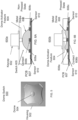
FIGS. 6A and 6B are illustrations of a switch including a metal dome, where a key cap may be in a first position inFIG. 6A and in a second position inFIG. 6B , and wherein a pre-trigger aiming function may be initiated by a conductive feature moving between the first and second positions; -
FIG. 7 is an illustration of a set of electronic and electro-optic components for use in performing and inductive pre-trigger aiming function; -
FIG. 8 is a flow diagram of a process for performing a pre-trigger aiming function by using inductive sensing by a code reader; -
FIG. 9 is a flow diagram of a process for a user of a code reader to set a pre-trigger threshold level; and -
FIG. 10 is a flow diagram of a process for a code reader to perform a pre-trigger aiming function by using inductive sensing by a code reader. - With regard to
FIG. 1 , an illustration of an illustrativehandheld code reader 100 inclusive of a pre-trigger aiming function initiated by inductive sensing is shown. Thecode reader 100 includes amain structure 102 with awindow 104 via which optics (not shown) are able to scan or image machine-readable indicia (e.g., barcode, QR code, or other machine-readable code). Themain structure 102 is shown as a housing, but the main structure may alternatively be a holder configured to enable a mobile device, such as a mobile barcode scanner in the shape of a smartphone, for example, to be secured thereby. For example, themain structure 102 may alternatively include a flat surface on which a mobile device is placed and secured by sides extending upwards from the flat surface that are shaped to secure the mobile device to the flat surface. Thehandle 106 may be connected to themain housing 102, and be configured to house electronics for performing code reading and pre-trigger aiming functionality, as described further herein. Atrigger 108 may be positioned near a top portion of thehandle 106 just beneath themain body 102, and be configured to enable a user to transition thetrigger 108 between a resting position and a read position, where the read position causes the code reader to capture an image of a machine-readable indicia, as further described herein. In addition, in accordance with the principles provided herein, a pre-trigger aiming function may be initiated in response to the trigger causing an inductive change to occur, as further described herein. - With regard to
FIG. 2 , an illustration of an illustrative pre-trigger aimingillumination pattern 200 that aids a user in imaging a machine-readable indicia is shown. The pre-trigger aimingillumination pattern 200 is shown to includefirst illumination features 202a-202d (collectively 202) that define arectangle shape 204 along withsecond illumination features 206a-206d (collectively 206) defining asquare shape 208 located in a center region of therectangular shape 204. It should be understood that alternative pre-trigger aiming illumination patterns may be utilized, such as a plus-sign (+) disposed in a center region of therectangle shape 204, lines to define outside regions of therectangle shape 204, or any other shapes that defined corners, edges, or inner portions of a region that the code reader will image during operation of the code reader. In an embodiment, thepre-trigger illumination pattern 200 may include therectangle shape 204 or other shape only, insidesquare shape 208, or other shape only. - With regard to
FIGS. 3A and 3B , illustrations ofscenes pre-trigger aiming pattern 302 is displayed on a linear code or one-dimensional code 304a, such as a conventional barcode, and a two-dimensional code 304b, such as a QR code, is shown. Aiming light source(s) may any illumination source, including LED or laser. Thepre-trigger aiming pattern 302 may include only center features (e.g., a simple spot, for example) or only perimeter-defining features, or both, as further described herein. Thepre-trigger aiming pattern 302 may include perimeter-defining illumination features 306 andcenter feature 308, as provided inFIG. 2 . The perimeter-defining illumination features 306 may be used to aid a user imaging thecode 304a being read, and thecenter illumination feature 308 may show that the code reader is aiming centrally at thecode 304a. Similarly, the twodimensional code 304b is fully encompassed within the rectangle defined by the perimeter-defining illumination features 306, and thecenter illumination feature 308 is centrally located on the 2D code. - With regard to
FIG. 4A , an illustration of anillustrative trigger portion 400 of a code reader is shown. Atrigger 402 is shown in a resting position or state, and may include aconductive element 404 attached thereto. Theconductive element 404 may be formed of any material that may be sensed by sensing magnetic field distortion by an inductive sensor. Although theconductive element 404 may be disposed on thetrigger 402, alternative positions of theconductive element 404 may be utilized. Moreover, theconductive element 404 may be integrated into another component relative to the inductive sensor. - A
switch 406 may be mounted to a printed circuit board (PCB) 408, configured to be depressed by thetrigger 402. Theswitch 406 may be an electromechanical switch or other type of switch that is mechanically activated by thetrigger 402. ThePCB 408 may be positioned within a cavity defined by a handle of the code reader, and define a rigid support for theswitch 406 such that theswitch 406 has minimal or no compliance relative to thetrigger 402 when being operated by a user. By having minimal or no compliance, the code reader may be more robust over time as the amount of force needed to cause the code reader to perform reading functions may remain constant over time a warping or other elastic deformation of the support for theswitch 406 is less likely to occur. - With regard to
FIG. 4B , an illustration of thePCB 408 on which theswitch 406 is coupled in proximate relation to anantenna 410 disposed on thePCB 408 is shown. Theantenna 410 may be a circular antenna that encircles theswitch 406. In an embodiment, theantenna 410 may include multiple, concentric circular antennas, as shown. Theantenna 410 may be printed on thePCB 408, and be in electrical communication with processing electronics (see, for example,FIG. 7 ) that are capable of processing signals, in this case magnetic field distortion signals or inductive change signals sensed by theantenna 410. Although theantenna 410 may be formed by circular antennas, it should be understood that alternative antenna shapes may be utilized. It should further be understood that rather than theantenna 410 being positioned on thePCB 408, theantenna 410 may be positioned elsewhere and be capable of sensing an inductive change resulting from a user moving thetrigger 402 that causes a conductive element to move. For example, an antenna may be positioned on or in thetrigger 402 and a conductive element may be positioned in relative position to thetrigger 402. Alternatively, theantenna 410 may be positioned on or in the main housing of the code reader. By applying theantenna 410 on thePCB 408, space and cost is saved by not having an extra PCB as when an optical sensor for sensing position of thetrigger 402 as has been previously utilized. - With regard to
FIG. 4C , an illustration of thetrigger portion 400 with thetrigger 402 in a read position in which thetrigger 402 causes a switch to be activated is shown. As configured, a trigger plunger or theconductive element 404 may depress theswitch 406 mounted to thePCB 408. In operation, as thetrigger 402 is pulled from the resting state (FIG. 4A ) to the image state (FIG. 4C ), theconductive element 404 moves through a variation of inductance, thereby enabling theantenna 410 to sense an inductive change. - More particularly, the inductive sensing may be performed using a high-resolution, high-speed inductive-to-digital converter (see
FIG. 7 ). The inductive sensing may be designed for a number of different functions and/or applications to be performed by the code reader based on the inductivity measurements. It is possible to detect position, rotation, or motion of an object, such as thetrigger 402. The converter allows both inductance and impedance to be measured. Featuring a wide inductor-capacitor (LC) sensor frequency range, a broad range of conductive materials of theconductive element 404 may be sensed. By using inductive sensing, inherently accurate and robust sensing, even in harsh industrial environments, may be utilized. - With regard to
FIG. 5 , an illustration of anillustrative dome switch 500 that may be utilized to initiate an imaging function and, optionally, pre-trigger aiming function in accordance with the principles described herein is shown. Thedome switch 500 may include a housing 502 anddome 504. Thedome 504 may be a flexible material, such as a flexible metal, so as to be able to be repetitively deformed without permanently damaging the dome shape. In an embodiment, thedome 504 may be conductive, and be utilized to be sensed by an inductive sensor, as further described inFIGS. 6A and 6B . - With regard to
FIGS. 6A and 6B , illustrations ofswitch assembly 600a in a non-pressed state and switch assembly in a pressed state are shown. Theswitch assembly 600a may include akeycap 602 that includes a dome activator feature or key 604 that protrudes from a bottom surface of thekeycap 602 so as to engage adome switch 605 and depress ametallic dome 606 of thedome switch 605 mounted to aPCB 607. In an embodiment, in the non-pressed state, thedome activator feature 604 may contact or be slightly above thedome 606, but not deform thedome 606, and in the pressed state, thedome activator feature 604 may deform the dome and cause the dome to be pressed into acontact 608b ofcontacts 608a-608c so as to activate theswitch 605. In an embodiment, theswitch assembly 600a may include thekeycap 602 and switch 605 in a common package. Alternatively, thekeycap 602 may be positioned on a trigger of a code reader and aligned with thedome 606 of theswitch 605 so that when the trigger is pulled to an image trigger position, thedome activator feature 604 of thekeycap 602 deforms thedome 606, thereby causing a pre-trigger aiming function to be initiated, as described below. When thedome 606 is deformed to be in an image activation state, thedome 606 contacts thecontact 608b, to cause a circuit to be completed and an electrical signal to be communicated to a processor to initiate an image capture, for example, by the code reader. - As further shown, an inductive change sensor or
antenna 610 may be printed on, mounted to, or positioned at a PCB 612 on which theswitch 605 is mounted. Theantenna 610 may be a circular antenna, such as theantenna 410 ofFIG. 4B . In this embodiment, rather than having a separate conductive element positioned on the trigger, such as shown inFIG. 4A , themetal dome 606 of thedome switch 605 may be utilized as the conductive element. That is, as themetal dome 606 is deformed, an inductive change may be sensed by theantenna 610. The shape, size, and spacing of theantenna 610 relative to thedome switch 605 may vary depending on the desired sensitivity, which may be a function of an antenna pattern produced by theantenna 610. As understood in the art, different antenna designs may produce different antenna patterns. - As previously described, by using the
antenna 610 capable of high-resolution and high-precision measurement of a magnetic field distortion within an antenna pattern (i.e., sensing region), it is possible to avoid using a conductive element on the trigger, such as theconductive element 404 ofFIG. 4A , and directly detect deformation of the conductivemetallic dome 606 inside theswitch 605 mounted on thePCB 607. That is, even a micrometric deformation of themetallic dome 606 inside theswitch 605 mounted on the PCB is enough to be detected by sensor electronics with sufficient gain and signal-to-noise ratio. - With a regard of
FIG. 7 , a block diagram of anelectrical system 700 including a set of electronic, electro-optic, and electromagnetic components for use in performing an inductive pre-trigger aiming function by a code reader is shown. Theelectrical system 700 may include electronics, including aprocessor 702, which may include a microprocessor, application specific integrated circuit (ASIC), and/or other electronics, configured to sense inductive changes and perform code reading functionality in accordance with the principles described herein. Anantenna 704, which may be a circular antenna with one or more circular antenna elements, may be configured to sense inductive changes caused by a trigger of the code reader moving aconductive element 706. Theconductive element 706 may be formed of any conductive material that may be sensed by theantenna 704. - The
antenna 704 may be in electrical communication with an inductance-to-digital (I/D)converter 708, which may be in electrical communication with theprocessor 702. The processor may further be in communication with aswitch 710, aimingilluminator 712, imaging illuminator 713, andimager 714. Theprocessor 702 may be configured to manage the functional operations of the code reader, including a pre-trigger aiming function and code imaging and decoding function. - In operation, in response to the
antenna 704 sensing an inductive level and/or inductive change, aninductive sense signal 716 may be produced. Theinductive sense signal 716 may be an analog signal that is dynamic to represent an inductive change or relative position of a conductive element, a sinusoidal signal in response to sensing the inductive change, or any other analog signal. Theinductive sense signal 716 may be received and processed by the I/D converter 708. The I/D converter 708 may generate an inductive sensedigital signal 708 that digitally represents theinductive sense signal 716. - The
processor 702 may receive the inductive sensedigital signal 718 and determine an inductive level of the correspondinginductive sense signal 716 to determine whether the inductive level is at a level to initiate a pre-trigger aiming function. In determining whether the inductive level is indicative to initiate the pre-trigger aiming function, a comparison may be made by theprocessor 702 between the instant inductive level and a baseline inductive level when the trigger, and consequently theconductive element 706, is in a resting state or position. The inductive sensing may be passive or active. In response to theprocessor 702 determining that the instant inductive level crosses a pre-trigger aiming function threshold level, theprocessor 702 may generate apre-trigger aiming signal 720 to cause the aimingilluminator 712 to generate a pre-trigger aiming pattern signal 722 within aprojection zone 724 to generate apre-trigger aiming pattern 726. For example, the instant inductive level may start at 0.0 Henry (self-calibrated) at a resting state and end at 0.5 Henry at the point when a switch is activated. If a pre-trigger aiming function threshold level is set at 0.25 Henry (e.g., corresponding to 2mm trigger pull), then the pre-trigger aiming function may be triggered when the trigger is pulled 2mm, and the inductive level may be 0.25 Henry, which is a difference of 0.25 Henry from the resting state. Theprojection zone 724 may be the same or similar angle as an angle defining a field-of-view 726 of theimager 714 used to capture an image or scan a scene in which a machine-readable indicia orcode 730 is positioned. That is, theprojection zone 724 is to overlap the scene within the field-of-view 726 of theimager 714. - In response to the
switch 710 generating aswitch signal 732 by the trigger activating theswitch 710 by pressing on theswitch 710, theprocessor 702 may generate animage capture signal 708 to cause theimager 714 to capture an image within the field-of-view 728. Similarly, in addition to theprocessor 702 generating theimage capture signal 708, theprocessor 702 may generate animaging illumination signal 736 to cause animaging illuminator 738 to generate an illumination signal (not shown) that illuminates thecode 730 being imaged. As with the pre-trigger aiming pattern signal 722, the illumination signal may have the same or similar field-of-view as theimager 714 such that thecode 730 is illuminated. In an embodiment, theimaging illuminator 738 may be turned to an ON state prior to theimager 714 capturing an image so that thecode 730 is illuminated prior to theimager 714 capturing an image of thecode 730. Theimager 714 may generateimage data 734 for theprocessor 702 to process and decode the machine-readable indicia 730, as understood in the art. - The
code reader 700 may further include auser interface 740 in electrical communication with theprocessor 702. Theuser interface 740 may include an electronic display that is touch sensitive such that a graphical user interface may be displayed for a user to set up ad operate thecode reader 700. In an alternative embodiment, theuser interface 740 may include electromechanical components, such as knobs, switches, or otherwise, that enable a user to set parameters, such as a pre-trigger aiming threshold level. Theuser interface 740 may be positioned on thecode reader 700, but may also be positioned on an external device. Such external positioning of a user interface may be the case in which thecode reader 700 is connected wirelessly or with cables to a personal computer or other electronic device to be configured, where the configuration options may be a pre-trigger setting option for setting responsiveness and behavior of the pre-trigger aiming function. Because some code readers do not have a user interface, enabling an external user interface to establish pre-trigger aiming or other settings may be more efficient and less costly than alternative techniques for establishing the pre-trigger aiming or other settings. In an embodiment, theuser interface 740 may enable a user to select a factory setting for the pre-trigger aiming threshold level, which may have multiple selection options (e.g., low, medium, high) or allow for a user to select a level within a range. - As shown, a user may interact with the
user interface 740 to select a pre-trigger aiminginductance level 742, which may be communicated from theuser interface 740 to theprocessor 702. Thecode reader 700 may have a factory setting for the pre-trigger aiming threshold level as a default and be selectable or resettable to the factory setting. The pre-trigger aiming threshold level may be stored in a non-transitory memory, and accessed during operation of thecode reader 700. In an alternative embodiment, rather than performing a resting-state inductance level comparison with an instant inductance, the code reader may be configured with the ability to let the user set the inductive threshold level while pulling the trigger to a desired threshold location (e.g., pull the trigger a desired amount and press a button). The processor may store the inductive value measured at the desired trigger location, and thereafter, the reader may use that stored inductive threshold level for determining an inductive change. - With regard to
FIG. 8 , a flow diagram of aprocess 800 for self-calibrating a code reader to perform a pre-trigger aiming function by using inductive sensing is shown. Theprocess 800 may start atstep 802, where a determination may be made as to whether a trigger of the code reader in a resting position. If not, then the process may repeatstep 802. In being in a resting position, a user may notify the code reader (i.e., a processor of the code reader) via a user interface (e.g., touch screen, mechanical button, or otherwise) that a trigger of the code reader is in a resting position (i.e., not being pulled toward a switch). Atstep 804, a resting position inductive value may be measured by an inductive sensor. Atstep 806, the resting position inductive value may be stored in a non-transitory memory for use as a reference value for inductive changes during operation of the code reader. - As previously described, the code reader may be configured to self-calibrate in a resting position to set a base inductive value. In one embodiment, a manufacturer may set the pre-trigger inductive threshold level. The self-calibration process may be independent of establishing a pre-trigger threshold level and independent of the pre-trigger threshold level. In another embodiment, a user may set the pre-trigger inductive threshold level by allowing the user to pull the trigger to a desired position and pressing a button that causes the code reader to store a pre-trigger inductive threshold level. Alternative techniques may be utilized to enable the user to configure the pre-trigger threshold. During operation, the pre-trigger aiming function is to be initiated when the inductive change is greater than the pre-trigger inductive threshold level as offset by the resting inductive value or crosses a pre-trigger inductive value set by the user moving the trigger to a desired location.
- With regard to
FIG. 9 , a flow diagram of aprocess 900 for a user of a code reader to set a pre-trigger threshold level is shown. In thisprocess 900, the pre-trigger threshold is configurable by the user. Theprocess 900 may start atstep 902, where a user moves a trigger to a desired pre-trigger threshold level position. Atstep 904, a pre-trigger inductive threshold level may be measured by an inductive sensor. To initiatestep 904, a user may press a button or hold the trigger at a certain location for a certain time period, such as 3 seconds, if the code reader in a user calibration mode, for example. Atstep 906, the pre-trigger inductive threshold level may be stored at a threshold level for determining when to initiate a pre-trigger aiming function during normal operation of the code reader. - With regard to
FIG. 10 , a flow diagram of aprocess 1000 for a code reader to perform a pre-trigger aiming function by using inductive sensing by a code reader is shown. Theprocess 1000 may start atstep 1002 by sensing an instant inductive value during operation of a trigger of the code reader. Atstep 1004, an inductive change from a resting position of the code reader may be determined. The determination may be performed by previously performing a self-calibration operation as provided inFIG. 8 or a user setting operation as provided inFIG. 9 . Atstep 1006, a determination may be made as to whether an inductive change crosses a pre-trigger inductive threshold level. The pre-trigger inductive threshold level may be set to a minimum level that is indicative of a user intentionally moving the trigger by a certain distance (e.g., 3mm move of the trigger). The pre-trigger inductive threshold level, for example, may be set to a corresponding inductive value that corresponds to a certain distance of movement. It should be understood that the minimum level may be set based on the type of conductive element is being sensed, type of inductive sensor, sensitivity of the inductive sensor, signal-to-noise level of the inductive sensor, resolution of an inductance-to-digital converter, or otherwise. - If at step 1006 a determination is made that the inductive change does not cross the pre-trigger inductive threshold level, then the process returns to step 1002. Otherwise, if the inductive change does cross the pre-trigger inductive threshold level, then the process may continue to step 1008, where a pre-trigger aiming function may be performed. Once such pre-trigger aiming function may include generating a pre-trigger aiming signal to display a pre-trigger aiming pattern to assist the user image a machine-readable indicia with the code reader, as previously described herein.
- One embodiment of a process of operating a code reader may include sensing an inductive change during operation of a trigger of the code reader, and in response to determining that the inductive change crosses a pre-trigger inductive threshold level, performing a pre-trigger aiming function.
- The process may further include sensing an inductive change by sensing an inductive change in response to an inductive device moving through an electromagnetic field. Sensing an inductive change may further include sensing an inductive change in response to a metallic dome of a dome switch being deformed by a trigger of the code reader.
- The code reader may be self-calibrated by sensing a resting-state inductive value, and storing the resting-state inductive value. Sensing the inductive change may include sensing an instant inductive value, determining a difference inductive value between the instant inductive value and the resting-state inductive value, and in response to the difference inductive value crossing the pre-trigger inductive threshold level, performing the pre-trigger aiming function. Sensing an inductive change may further include sensing and inductive change until a button is pressed to cause the code reader to perform a scan function.
- The foregoing method descriptions and the process flow diagrams are provided merely as illustrative examples and are not intended to require or imply that the steps of the various embodiments must be performed in the order presented. As will be appreciated by one of skill in the art, the steps in the foregoing embodiments may be performed in any order. Words such as "then," "next," etc. are not intended to limit the order of the steps; these words are simply used to guide the reader through the description of the methods. Although process flow diagrams may describe the operations as a sequential process, many of the operations may be performed in parallel or concurrently. In addition, the order of the operations may be rearranged. A process may correspond to a method, a function, a procedure, a subroutine, a subprogram, etc. When a process corresponds to a function, its termination may correspond to a return of the function to the calling function or the main function.
- The various illustrative logical blocks, modules, circuits, and algorithm steps described in connection with the embodiments disclosed here may be implemented as electronic hardware, computer software, or combinations of both. To clearly illustrate this interchangeability of hardware and software, various illustrative components, blocks, modules, circuits, and steps have been described above generally in terms of their functionality. Whether such functionality is implemented as hardware or software depends upon the particular application and design constraints imposed on the overall system. Skilled artisans may implement the described functionality in varying ways for each particular application, but such implementation decisions should not be interpreted as causing a departure from the scope of the present invention.
- Embodiments implemented in computer software may be implemented in software, firmware, middleware, microcode, hardware description languages, or any combination thereof. A code segment or machine-executable instructions may represent a procedure, a function, a subprogram, a program, a routine, a subroutine, a module, a software package, a class, or any combination of instructions, data structures, or program statements. A code segment may be coupled to and/or in communication with another code segment or a hardware circuit by passing and/or receiving information, data, arguments, parameters, or memory contents. Information, arguments, parameters, data, etc. may be passed, forwarded, or transmitted via any suitable means including memory sharing, message passing, token passing, network transmission, etc.
- The actual software code or specialized control hardware used to implement these systems and methods is not limiting of the invention. Thus, the operation and behavior of the systems and methods were described without reference to the specific software code being understood that software and control hardware can be designed to implement the systems and methods based on the description here.
- When implemented in software, the functions may be stored as one or more instructions or code on a non-transitory computer-readable or processor-readable storage medium. The steps of a method or algorithm disclosed here may be embodied in a processor-executable software module which may reside on a computer-readable or processor-readable storage medium. A non-transitory computer-readable or processor-readable media includes both computer storage media and tangible storage media that facilitate transfer of a computer program from one place to another. A non-transitory processor-readable storage media may be any available media that may be accessed by a computer. By way of example, and not limitation, such non-transitory processor-readable media may comprise RAM, ROM, EEPROM, CD-ROM or other optical disk storage, magnetic disk storage or other magnetic storage devices, or any other tangible storage medium that may be used to store desired program code in the form of instructions or data structures and that may be accessed by a computer or processor. Disk and disc, as used here, include compact disc (CD), laser disc, optical disc, digital versatile disc (DVD), floppy disk, and Blu-ray disc where disks usually reproduce data magnetically, while discs reproduce data optically with lasers. Combinations of the above should also be included within the scope of computer-readable media. Additionally, the operations of a method or algorithm may reside as one or any combination or set of codes and/or instructions on a non-transitory processor-readable medium and/or computer-readable medium, which may be incorporated into a computer program product.
- The previous description is of a preferred embodiment for implementing the invention, and the scope of the invention should not necessarily be limited by this description. The scope of the present invention is instead defined by the following claims.
Claims (15)
- A handheld code reader (100, 700), comprising:a main structure (102);a handle (106) extending from the main structure (102);a trigger (108, 402) configured to be pulled by a finger of a user holding the handle (106);characterised bya conductive element (404, 504, 606, 706);an antenna (410, 610, 704) configured to sense an inductive change caused by the trigger (108, 402) moving the conductive element (404, 504, 606, 706); andelectronics in electrical communication with the antenna (410, 610, 704), and configured to determine when the inductive change is indicative of a user selecting to activate a pre-trigger aiming function.
- The code reader (100, 700) according to claim 1, wherein the electronics are configured to determine when the inductive change is indicative of the user selecting to activate a pre-trigger aiming function includes sensing when a difference between a resting-state inductive value and an instant inductive value crosses a pre-trigger inductive threshold level.
- The code reader (100, 700) according to any of claims 1-2, wherein the antenna (410, 610, 704) is a circular antenna (410, 610, 704), preferably positioned at the handle (106).
- The code reader (100, 700) according to any of claims 1-3, wherein the electronics are further configured to enable a user to set a or the pre-trigger aiming threshold level, which when crossed by the inductive change, causes the electronics to initiate the pre-trigger aiming function.
- The code reader (100, 700) according to any of claims 1-4, wherein the conductive element (404) is positioned on the trigger (108, 402).
- The code reader (100, 700) according to any of claims 1-4, further comprising a switch (605, 710) positioned to be pressed by the trigger (108, 402), and wherein the conductive element (504, 606, 706) is a metal dome (504, 606) on the switch (605, 710).
- The code reader (100, 700) according to claim 6, wherein the antenna (610, 704) is configured to sense the inductive change in response to the metal dome (504, 606) being deformed by the trigger (108, 402), wherein preferably the antenna (410, 610, 704) encircles the switch (406, 605, 710).
- The code reader (100, 700) according to any of claims 1-7, wherein the electronics, in response to determining when the inductive change crosses a or the pre-trigger inductive threshold level, causes a pre-trigger aiming illumination pattern (726) to be projected from the code reader (100, 700).
- The code reader (100, 700) according to any of claims 1-8, further comprising:electro-optics positioned at the main structure (102), and configured to image or scan machine-readable codes (304a, 304b, 730);a or said switch (406, 605, 710) in electrical communication with the electronics, and positioned to be activated by the trigger (108, 402) being pulled to a scan position,wherein the electronics is further configured to cause the electro-optics to perform (i) a pre-trigger aiming function and (ii) a code reading function.
- The code reader according to any of the previous claims, wherein the electronics are configured to determine a resting-state inductive value when the trigger is in a resting position, and to store the resting-state inductive value as a reference value.
- A method of operating a code reader (100, 700), comprising:sensing an inductive change during operation of a trigger (108, 402) of the code reader (100, 700); andin response to determining that the inductive change crosses a pre-trigger inductive threshold level, performing a pre-trigger aiming function.
- The method according to claim 11, wherein sensing an inductive change includes sensing an inductive change in response to an inductive device moving through an electromagnetic field, preferably in response to a metallic dome (504, 606) of a dome switch (500, 605) being deformed by a trigger (108, 402) of the code reader (100, 700).
- The method according to any of claims 11-12, further comprising self-calibrating the code reader by:sensing a resting-state inductive value; andstoring the resting-state inductive value.
- The method according to claim 13, wherein sensing the inductive change includes:sensing an instant inductive value;determining a difference inductive value between the instant inductive value and the resting-state inductive value; andin response to the difference inductive value crossing the pre-trigger inductive threshold level, performing the pre-trigger aiming function.
- The method according to any of claims 11-14, further comprising enabling a user to set the pre-trigger aiming threshold level.
Applications Claiming Priority (1)
| Application Number | Priority Date | Filing Date | Title |
|---|---|---|---|
| US17/133,214 US11416697B2 (en) | 2020-12-23 | 2020-12-23 | Inductive aiming trigger |
Publications (2)
| Publication Number | Publication Date |
|---|---|
| EP4020307A1 EP4020307A1 (en) | 2022-06-29 |
| EP4020307B1 true EP4020307B1 (en) | 2023-07-05 |
Family
ID=78957261
Family Applications (1)
| Application Number | Title | Priority Date | Filing Date |
|---|---|---|---|
| EP21215412.4A Active EP4020307B1 (en) | 2020-12-23 | 2021-12-17 | Inductive aiming trigger |
Country Status (3)
| Country | Link |
|---|---|
| US (1) | US11416697B2 (en) |
| EP (1) | EP4020307B1 (en) |
| CN (1) | CN114662506B (en) |
Family Cites Families (12)
| Publication number | Priority date | Publication date | Assignee | Title |
|---|---|---|---|---|
| US5059778A (en) * | 1986-09-29 | 1991-10-22 | Mars Incorporated | Portable data scanner apparatus |
| EP0999515A3 (en) * | 1998-11-02 | 2001-08-29 | PSC Scanning, Inc. | Multi-stage trigger for a data reading device |
| US7559473B2 (en) * | 2005-09-15 | 2009-07-14 | Symbol Technologies Inc. | Sensor for activating an aiming pattern of a handheld scanner |
| US20080129532A1 (en) | 2006-11-30 | 2008-06-05 | David Bellows | System and Method for Activating a Mobile Device |
| US8479993B2 (en) * | 2011-07-29 | 2013-07-09 | Symbol Technologies, Inc. | Method for aiming imaging scanner with single trigger |
| CN103473525B (en) * | 2012-06-07 | 2016-04-06 | 环旭电子股份有限公司 | Handheld barcode scanner |
| US20150178539A1 (en) | 2013-12-20 | 2015-06-25 | Cognex Corporation | Image module including mounting and decoder for mobile devices |
| US9117129B1 (en) | 2015-02-05 | 2015-08-25 | Symbol Technologies, Llc | Predictive triggering in an electronic device |
| US10325436B2 (en) | 2015-12-31 | 2019-06-18 | Hand Held Products, Inc. | Devices, systems, and methods for optical validation |
| US10803265B2 (en) * | 2018-03-22 | 2020-10-13 | Symbol Technologies, Llc | Aiming light patterns for use with barcode readers and devices systems and methods associated therewith |
| CN109274364B (en) * | 2018-09-06 | 2022-08-30 | 佛山市顺德区美的洗涤电器制造有限公司 | Pressing detection method and device for magnetic control knob and storage medium |
| JP7366577B2 (en) * | 2019-04-15 | 2023-10-23 | 株式会社キーエンス | Optical information reading device and optical information reading method |
-
2020
- 2020-12-23 US US17/133,214 patent/US11416697B2/en active Active
-
2021
- 2021-12-17 EP EP21215412.4A patent/EP4020307B1/en active Active
- 2021-12-21 CN CN202111568270.9A patent/CN114662506B/en active Active
Also Published As
| Publication number | Publication date |
|---|---|
| CN114662506B (en) | 2025-08-01 |
| US20220198165A1 (en) | 2022-06-23 |
| CN114662506A (en) | 2022-06-24 |
| US11416697B2 (en) | 2022-08-16 |
| EP4020307A1 (en) | 2022-06-29 |
Similar Documents
| Publication | Publication Date | Title |
|---|---|---|
| US10741347B2 (en) | Tactile switch for a mobile electronic device | |
| US9639726B2 (en) | Code symbol reading system having adjustable object detection | |
| US9805237B2 (en) | Cancelling noise caused by the flicker of ambient lights | |
| US10311274B2 (en) | Reader for optical indicia presented under two or more imaging conditions within a single frame time | |
| US20140374485A1 (en) | System and Method for Reading Code Symbols Using a Variable Field of View | |
| KR100827621B1 (en) | Input device | |
| EP3151553A1 (en) | A self-calibrating projection apparatus and process | |
| CN114662517B (en) | Indicia reading apparatus and method for decoding decodable indicia using stereoscopic imaging | |
| WO2012103608A1 (en) | Indicia reading terminal operable for data input on two sides | |
| US20180068145A1 (en) | Smart scan peripheral | |
| US11416697B2 (en) | Inductive aiming trigger | |
| US20070084926A1 (en) | Functional aiming system for an automatic data collection device, such as an image acquisition device | |
| US20030021284A1 (en) | Coordinate input apparatus including an optical movement detection device used for optically inputting coordinates and pressed for switching a switch device | |
| US20090266897A1 (en) | Floating trigger assembly in electro-optical reader | |
| JP7024620B2 (en) | Portable information reader | |
| US9940497B2 (en) | Minimizing laser persistence on two-dimensional image sensors | |
| JPH07146102A (en) | Position detector | |
| JP2003196019A (en) | Magnetic sensor array and pointing device | |
| EP1708220A1 (en) | Multi-operational input device | |
| JP2006049015A (en) | Input device and electronic equipment using it | |
| JP7163702B2 (en) | Electronics | |
| JP5626064B2 (en) | Mobile device | |
| US9892356B1 (en) | Backlit display detection and radio signature recognition | |
| JP2010231437A (en) | Code symbol reader | |
| KR20100035968A (en) | Optical pointing device and portable terminal having the same |
Legal Events
| Date | Code | Title | Description |
|---|---|---|---|
| PUAI | Public reference made under article 153(3) epc to a published international application that has entered the european phase |
Free format text: ORIGINAL CODE: 0009012 |
|
| STAA | Information on the status of an ep patent application or granted ep patent |
Free format text: STATUS: THE APPLICATION HAS BEEN PUBLISHED |
|
| AK | Designated contracting states |
Kind code of ref document: A1 Designated state(s): AL AT BE BG CH CY CZ DE DK EE ES FI FR GB GR HR HU IE IS IT LI LT LU LV MC MK MT NL NO PL PT RO RS SE SI SK SM TR |
|
| STAA | Information on the status of an ep patent application or granted ep patent |
Free format text: STATUS: REQUEST FOR EXAMINATION WAS MADE |
|
| 17P | Request for examination filed |
Effective date: 20221220 |
|
| RBV | Designated contracting states (corrected) |
Designated state(s): AL AT BE BG CH CY CZ DE DK EE ES FI FR GB GR HR HU IE IS IT LI LT LU LV MC MK MT NL NO PL PT RO RS SE SI SK SM TR |
|
| GRAP | Despatch of communication of intention to grant a patent |
Free format text: ORIGINAL CODE: EPIDOSNIGR1 |
|
| STAA | Information on the status of an ep patent application or granted ep patent |
Free format text: STATUS: GRANT OF PATENT IS INTENDED |
|
| INTG | Intention to grant announced |
Effective date: 20230405 |
|
| GRAS | Grant fee paid |
Free format text: ORIGINAL CODE: EPIDOSNIGR3 |
|
| GRAA | (expected) grant |
Free format text: ORIGINAL CODE: 0009210 |
|
| STAA | Information on the status of an ep patent application or granted ep patent |
Free format text: STATUS: THE PATENT HAS BEEN GRANTED |
|
| AK | Designated contracting states |
Kind code of ref document: B1 Designated state(s): AL AT BE BG CH CY CZ DE DK EE ES FI FR GB GR HR HU IE IS IT LI LT LU LV MC MK MT NL NO PL PT RO RS SE SI SK SM TR |
|
| P01 | Opt-out of the competence of the unified patent court (upc) registered |
Effective date: 20230525 |
|
| REG | Reference to a national code |
Ref country code: CH Ref legal event code: EP |
|
| REG | Reference to a national code |
Ref country code: AT Ref legal event code: REF Ref document number: 1585503 Country of ref document: AT Kind code of ref document: T Effective date: 20230715 |
|
| REG | Reference to a national code |
Ref country code: DE Ref legal event code: R096 Ref document number: 602021003287 Country of ref document: DE |
|
| REG | Reference to a national code |
Ref country code: IE Ref legal event code: FG4D |
|
| REG | Reference to a national code |
Ref country code: LT Ref legal event code: MG9D |
|
| REG | Reference to a national code |
Ref country code: NL Ref legal event code: MP Effective date: 20230705 |
|
| REG | Reference to a national code |
Ref country code: AT Ref legal event code: MK05 Ref document number: 1585503 Country of ref document: AT Kind code of ref document: T Effective date: 20230705 |
|
| PG25 | Lapsed in a contracting state [announced via postgrant information from national office to epo] |
Ref country code: NL Free format text: LAPSE BECAUSE OF FAILURE TO SUBMIT A TRANSLATION OF THE DESCRIPTION OR TO PAY THE FEE WITHIN THE PRESCRIBED TIME-LIMIT Effective date: 20230705 |
|
| PG25 | Lapsed in a contracting state [announced via postgrant information from national office to epo] |
Ref country code: GR Free format text: LAPSE BECAUSE OF FAILURE TO SUBMIT A TRANSLATION OF THE DESCRIPTION OR TO PAY THE FEE WITHIN THE PRESCRIBED TIME-LIMIT Effective date: 20231006 |
|
| PG25 | Lapsed in a contracting state [announced via postgrant information from national office to epo] |
Ref country code: ES Free format text: LAPSE BECAUSE OF FAILURE TO SUBMIT A TRANSLATION OF THE DESCRIPTION OR TO PAY THE FEE WITHIN THE PRESCRIBED TIME-LIMIT Effective date: 20230705 |
|
| PG25 | Lapsed in a contracting state [announced via postgrant information from national office to epo] |
Ref country code: IS Free format text: LAPSE BECAUSE OF FAILURE TO SUBMIT A TRANSLATION OF THE DESCRIPTION OR TO PAY THE FEE WITHIN THE PRESCRIBED TIME-LIMIT Effective date: 20231105 |
|
| PG25 | Lapsed in a contracting state [announced via postgrant information from national office to epo] |
Ref country code: SE Free format text: LAPSE BECAUSE OF FAILURE TO SUBMIT A TRANSLATION OF THE DESCRIPTION OR TO PAY THE FEE WITHIN THE PRESCRIBED TIME-LIMIT Effective date: 20230705 Ref country code: RS Free format text: LAPSE BECAUSE OF FAILURE TO SUBMIT A TRANSLATION OF THE DESCRIPTION OR TO PAY THE FEE WITHIN THE PRESCRIBED TIME-LIMIT Effective date: 20230705 Ref country code: PT Free format text: LAPSE BECAUSE OF FAILURE TO SUBMIT A TRANSLATION OF THE DESCRIPTION OR TO PAY THE FEE WITHIN THE PRESCRIBED TIME-LIMIT Effective date: 20231106 Ref country code: NO Free format text: LAPSE BECAUSE OF FAILURE TO SUBMIT A TRANSLATION OF THE DESCRIPTION OR TO PAY THE FEE WITHIN THE PRESCRIBED TIME-LIMIT Effective date: 20231005 Ref country code: LV Free format text: LAPSE BECAUSE OF FAILURE TO SUBMIT A TRANSLATION OF THE DESCRIPTION OR TO PAY THE FEE WITHIN THE PRESCRIBED TIME-LIMIT Effective date: 20230705 Ref country code: LT Free format text: LAPSE BECAUSE OF FAILURE TO SUBMIT A TRANSLATION OF THE DESCRIPTION OR TO PAY THE FEE WITHIN THE PRESCRIBED TIME-LIMIT Effective date: 20230705 Ref country code: IS Free format text: LAPSE BECAUSE OF FAILURE TO SUBMIT A TRANSLATION OF THE DESCRIPTION OR TO PAY THE FEE WITHIN THE PRESCRIBED TIME-LIMIT Effective date: 20231105 Ref country code: HR Free format text: LAPSE BECAUSE OF FAILURE TO SUBMIT A TRANSLATION OF THE DESCRIPTION OR TO PAY THE FEE WITHIN THE PRESCRIBED TIME-LIMIT Effective date: 20230705 Ref country code: GR Free format text: LAPSE BECAUSE OF FAILURE TO SUBMIT A TRANSLATION OF THE DESCRIPTION OR TO PAY THE FEE WITHIN THE PRESCRIBED TIME-LIMIT Effective date: 20231006 Ref country code: FI Free format text: LAPSE BECAUSE OF FAILURE TO SUBMIT A TRANSLATION OF THE DESCRIPTION OR TO PAY THE FEE WITHIN THE PRESCRIBED TIME-LIMIT Effective date: 20230705 Ref country code: ES Free format text: LAPSE BECAUSE OF FAILURE TO SUBMIT A TRANSLATION OF THE DESCRIPTION OR TO PAY THE FEE WITHIN THE PRESCRIBED TIME-LIMIT Effective date: 20230705 Ref country code: AT Free format text: LAPSE BECAUSE OF FAILURE TO SUBMIT A TRANSLATION OF THE DESCRIPTION OR TO PAY THE FEE WITHIN THE PRESCRIBED TIME-LIMIT Effective date: 20230705 |
|
| PG25 | Lapsed in a contracting state [announced via postgrant information from national office to epo] |
Ref country code: PL Free format text: LAPSE BECAUSE OF FAILURE TO SUBMIT A TRANSLATION OF THE DESCRIPTION OR TO PAY THE FEE WITHIN THE PRESCRIBED TIME-LIMIT Effective date: 20230705 |
|
| REG | Reference to a national code |
Ref country code: DE Ref legal event code: R097 Ref document number: 602021003287 Country of ref document: DE |
|
| PG25 | Lapsed in a contracting state [announced via postgrant information from national office to epo] |
Ref country code: SM Free format text: LAPSE BECAUSE OF FAILURE TO SUBMIT A TRANSLATION OF THE DESCRIPTION OR TO PAY THE FEE WITHIN THE PRESCRIBED TIME-LIMIT Effective date: 20230705 Ref country code: RO Free format text: LAPSE BECAUSE OF FAILURE TO SUBMIT A TRANSLATION OF THE DESCRIPTION OR TO PAY THE FEE WITHIN THE PRESCRIBED TIME-LIMIT Effective date: 20230705 Ref country code: EE Free format text: LAPSE BECAUSE OF FAILURE TO SUBMIT A TRANSLATION OF THE DESCRIPTION OR TO PAY THE FEE WITHIN THE PRESCRIBED TIME-LIMIT Effective date: 20230705 Ref country code: DK Free format text: LAPSE BECAUSE OF FAILURE TO SUBMIT A TRANSLATION OF THE DESCRIPTION OR TO PAY THE FEE WITHIN THE PRESCRIBED TIME-LIMIT Effective date: 20230705 Ref country code: CZ Free format text: LAPSE BECAUSE OF FAILURE TO SUBMIT A TRANSLATION OF THE DESCRIPTION OR TO PAY THE FEE WITHIN THE PRESCRIBED TIME-LIMIT Effective date: 20230705 Ref country code: SK Free format text: LAPSE BECAUSE OF FAILURE TO SUBMIT A TRANSLATION OF THE DESCRIPTION OR TO PAY THE FEE WITHIN THE PRESCRIBED TIME-LIMIT Effective date: 20230705 |
|
| PLBE | No opposition filed within time limit |
Free format text: ORIGINAL CODE: 0009261 |
|
| STAA | Information on the status of an ep patent application or granted ep patent |
Free format text: STATUS: NO OPPOSITION FILED WITHIN TIME LIMIT |
|
| 26N | No opposition filed |
Effective date: 20240408 |
|
| PG25 | Lapsed in a contracting state [announced via postgrant information from national office to epo] |
Ref country code: SI Free format text: LAPSE BECAUSE OF FAILURE TO SUBMIT A TRANSLATION OF THE DESCRIPTION OR TO PAY THE FEE WITHIN THE PRESCRIBED TIME-LIMIT Effective date: 20230705 |
|
| PG25 | Lapsed in a contracting state [announced via postgrant information from national office to epo] |
Ref country code: LU Free format text: LAPSE BECAUSE OF NON-PAYMENT OF DUE FEES Effective date: 20231217 |
|
| PG25 | Lapsed in a contracting state [announced via postgrant information from national office to epo] |
Ref country code: MC Free format text: LAPSE BECAUSE OF FAILURE TO SUBMIT A TRANSLATION OF THE DESCRIPTION OR TO PAY THE FEE WITHIN THE PRESCRIBED TIME-LIMIT Effective date: 20230705 |
|
| REG | Reference to a national code |
Ref country code: BE Ref legal event code: MM Effective date: 20231231 |
|
| PG25 | Lapsed in a contracting state [announced via postgrant information from national office to epo] |
Ref country code: MC Free format text: LAPSE BECAUSE OF FAILURE TO SUBMIT A TRANSLATION OF THE DESCRIPTION OR TO PAY THE FEE WITHIN THE PRESCRIBED TIME-LIMIT Effective date: 20230705 Ref country code: LU Free format text: LAPSE BECAUSE OF NON-PAYMENT OF DUE FEES Effective date: 20231217 |
|
| REG | Reference to a national code |
Ref country code: IE Ref legal event code: MM4A |
|
| PG25 | Lapsed in a contracting state [announced via postgrant information from national office to epo] |
Ref country code: IE Free format text: LAPSE BECAUSE OF NON-PAYMENT OF DUE FEES Effective date: 20231217 |
|
| PG25 | Lapsed in a contracting state [announced via postgrant information from national office to epo] |
Ref country code: BE Free format text: LAPSE BECAUSE OF NON-PAYMENT OF DUE FEES Effective date: 20231231 |
|
| PG25 | Lapsed in a contracting state [announced via postgrant information from national office to epo] |
Ref country code: IE Free format text: LAPSE BECAUSE OF NON-PAYMENT OF DUE FEES Effective date: 20231217 Ref country code: BE Free format text: LAPSE BECAUSE OF NON-PAYMENT OF DUE FEES Effective date: 20231231 |
|
| PG25 | Lapsed in a contracting state [announced via postgrant information from national office to epo] |
Ref country code: BG Free format text: LAPSE BECAUSE OF FAILURE TO SUBMIT A TRANSLATION OF THE DESCRIPTION OR TO PAY THE FEE WITHIN THE PRESCRIBED TIME-LIMIT Effective date: 20230705 |
|
| PG25 | Lapsed in a contracting state [announced via postgrant information from national office to epo] |
Ref country code: BG Free format text: LAPSE BECAUSE OF FAILURE TO SUBMIT A TRANSLATION OF THE DESCRIPTION OR TO PAY THE FEE WITHIN THE PRESCRIBED TIME-LIMIT Effective date: 20230705 |
|
| PG25 | Lapsed in a contracting state [announced via postgrant information from national office to epo] |
Ref country code: CY Free format text: LAPSE BECAUSE OF FAILURE TO SUBMIT A TRANSLATION OF THE DESCRIPTION OR TO PAY THE FEE WITHIN THE PRESCRIBED TIME-LIMIT; INVALID AB INITIO Effective date: 20211217 |
|
| REG | Reference to a national code |
Ref country code: CH Ref legal event code: PL |
|
| PG25 | Lapsed in a contracting state [announced via postgrant information from national office to epo] |
Ref country code: CH Free format text: LAPSE BECAUSE OF NON-PAYMENT OF DUE FEES Effective date: 20241231 |
|
| PG25 | Lapsed in a contracting state [announced via postgrant information from national office to epo] |
Ref country code: TR Free format text: LAPSE BECAUSE OF FAILURE TO SUBMIT A TRANSLATION OF THE DESCRIPTION OR TO PAY THE FEE WITHIN THE PRESCRIBED TIME-LIMIT Effective date: 20230705 |
|
| PGFP | Annual fee paid to national office [announced via postgrant information from national office to epo] |
Ref country code: DE Payment date: 20251211 Year of fee payment: 5 |
|
| PGFP | Annual fee paid to national office [announced via postgrant information from national office to epo] |
Ref country code: IT Payment date: 20251223 Year of fee payment: 5 |
|
| PGFP | Annual fee paid to national office [announced via postgrant information from national office to epo] |
Ref country code: FR Payment date: 20251229 Year of fee payment: 5 |
|
| PG25 | Lapsed in a contracting state [announced via postgrant information from national office to epo] |
Ref country code: HU Free format text: LAPSE BECAUSE OF FAILURE TO SUBMIT A TRANSLATION OF THE DESCRIPTION OR TO PAY THE FEE WITHIN THE PRESCRIBED TIME-LIMIT; INVALID AB INITIO Effective date: 20211217 |