EP4020079A1 - Adjustable mounting system for a telepresence device - Google Patents
Adjustable mounting system for a telepresence device Download PDFInfo
- Publication number
- EP4020079A1 EP4020079A1 EP21205010.8A EP21205010A EP4020079A1 EP 4020079 A1 EP4020079 A1 EP 4020079A1 EP 21205010 A EP21205010 A EP 21205010A EP 4020079 A1 EP4020079 A1 EP 4020079A1
- Authority
- EP
- European Patent Office
- Prior art keywords
- salient
- section
- mounting system
- adjustable mounting
- scaffold unit
- Prior art date
- Legal status (The legal status is an assumption and is not a legal conclusion. Google has not performed a legal analysis and makes no representation as to the accuracy of the status listed.)
- Withdrawn
Links
Images





Classifications
-
- H—ELECTRICITY
- H04—ELECTRIC COMMUNICATION TECHNIQUE
- H04N—PICTORIAL COMMUNICATION, e.g. TELEVISION
- H04N7/00—Television systems
- H04N7/14—Systems for two-way working
- H04N7/141—Systems for two-way working between two video terminals, e.g. videophone
- H04N7/142—Constructional details of the terminal equipment, e.g. arrangements of the camera and the display
-
- G—PHYSICS
- G03—PHOTOGRAPHY; CINEMATOGRAPHY; ANALOGOUS TECHNIQUES USING WAVES OTHER THAN OPTICAL WAVES; ELECTROGRAPHY; HOLOGRAPHY
- G03B—APPARATUS OR ARRANGEMENTS FOR TAKING PHOTOGRAPHS OR FOR PROJECTING OR VIEWING THEM; APPARATUS OR ARRANGEMENTS EMPLOYING ANALOGOUS TECHNIQUES USING WAVES OTHER THAN OPTICAL WAVES; ACCESSORIES THEREFOR
- G03B17/00—Details of cameras or camera bodies; Accessories therefor
- G03B17/56—Accessories
- G03B17/561—Support related camera accessories
-
- H—ELECTRICITY
- H04—ELECTRIC COMMUNICATION TECHNIQUE
- H04N—PICTORIAL COMMUNICATION, e.g. TELEVISION
- H04N7/00—Television systems
- H04N7/14—Systems for two-way working
- H04N7/15—Conference systems
-
- F—MECHANICAL ENGINEERING; LIGHTING; HEATING; WEAPONS; BLASTING
- F16—ENGINEERING ELEMENTS AND UNITS; GENERAL MEASURES FOR PRODUCING AND MAINTAINING EFFECTIVE FUNCTIONING OF MACHINES OR INSTALLATIONS; THERMAL INSULATION IN GENERAL
- F16M—FRAMES, CASINGS OR BEDS OF ENGINES, MACHINES OR APPARATUS, NOT SPECIFIC TO ENGINES, MACHINES OR APPARATUS PROVIDED FOR ELSEWHERE; STANDS; SUPPORTS
- F16M11/00—Stands or trestles as supports for apparatus or articles placed thereon ; Stands for scientific apparatus such as gravitational force meters
- F16M11/02—Heads
- F16M11/04—Means for attachment of apparatus; Means allowing adjustment of the apparatus relatively to the stand
- F16M11/043—Allowing translations
- F16M11/048—Allowing translations adapted to forward-backward translation movement
-
- F—MECHANICAL ENGINEERING; LIGHTING; HEATING; WEAPONS; BLASTING
- F16—ENGINEERING ELEMENTS AND UNITS; GENERAL MEASURES FOR PRODUCING AND MAINTAINING EFFECTIVE FUNCTIONING OF MACHINES OR INSTALLATIONS; THERMAL INSULATION IN GENERAL
- F16M—FRAMES, CASINGS OR BEDS OF ENGINES, MACHINES OR APPARATUS, NOT SPECIFIC TO ENGINES, MACHINES OR APPARATUS PROVIDED FOR ELSEWHERE; STANDS; SUPPORTS
- F16M11/00—Stands or trestles as supports for apparatus or articles placed thereon ; Stands for scientific apparatus such as gravitational force meters
- F16M11/02—Heads
- F16M11/04—Means for attachment of apparatus; Means allowing adjustment of the apparatus relatively to the stand
- F16M11/06—Means for attachment of apparatus; Means allowing adjustment of the apparatus relatively to the stand allowing pivoting
- F16M11/10—Means for attachment of apparatus; Means allowing adjustment of the apparatus relatively to the stand allowing pivoting around a horizontal axis
- F16M11/105—Means for attachment of apparatus; Means allowing adjustment of the apparatus relatively to the stand allowing pivoting around a horizontal axis the horizontal axis being the roll axis, e.g. for creating a landscape-portrait rotation
-
- F—MECHANICAL ENGINEERING; LIGHTING; HEATING; WEAPONS; BLASTING
- F16—ENGINEERING ELEMENTS AND UNITS; GENERAL MEASURES FOR PRODUCING AND MAINTAINING EFFECTIVE FUNCTIONING OF MACHINES OR INSTALLATIONS; THERMAL INSULATION IN GENERAL
- F16M—FRAMES, CASINGS OR BEDS OF ENGINES, MACHINES OR APPARATUS, NOT SPECIFIC TO ENGINES, MACHINES OR APPARATUS PROVIDED FOR ELSEWHERE; STANDS; SUPPORTS
- F16M13/00—Other supports for positioning apparatus or articles; Means for steadying hand-held apparatus or articles
-
- F—MECHANICAL ENGINEERING; LIGHTING; HEATING; WEAPONS; BLASTING
- F16—ENGINEERING ELEMENTS AND UNITS; GENERAL MEASURES FOR PRODUCING AND MAINTAINING EFFECTIVE FUNCTIONING OF MACHINES OR INSTALLATIONS; THERMAL INSULATION IN GENERAL
- F16M—FRAMES, CASINGS OR BEDS OF ENGINES, MACHINES OR APPARATUS, NOT SPECIFIC TO ENGINES, MACHINES OR APPARATUS PROVIDED FOR ELSEWHERE; STANDS; SUPPORTS
- F16M13/00—Other supports for positioning apparatus or articles; Means for steadying hand-held apparatus or articles
- F16M13/02—Other supports for positioning apparatus or articles; Means for steadying hand-held apparatus or articles for supporting on, or attaching to, an object, e.g. tree, gate, window-frame, cycle
-
- F—MECHANICAL ENGINEERING; LIGHTING; HEATING; WEAPONS; BLASTING
- F16—ENGINEERING ELEMENTS AND UNITS; GENERAL MEASURES FOR PRODUCING AND MAINTAINING EFFECTIVE FUNCTIONING OF MACHINES OR INSTALLATIONS; THERMAL INSULATION IN GENERAL
- F16M—FRAMES, CASINGS OR BEDS OF ENGINES, MACHINES OR APPARATUS, NOT SPECIFIC TO ENGINES, MACHINES OR APPARATUS PROVIDED FOR ELSEWHERE; STANDS; SUPPORTS
- F16M13/00—Other supports for positioning apparatus or articles; Means for steadying hand-held apparatus or articles
- F16M13/02—Other supports for positioning apparatus or articles; Means for steadying hand-held apparatus or articles for supporting on, or attaching to, an object, e.g. tree, gate, window-frame, cycle
- F16M13/022—Other supports for positioning apparatus or articles; Means for steadying hand-held apparatus or articles for supporting on, or attaching to, an object, e.g. tree, gate, window-frame, cycle repositionable
-
- H—ELECTRICITY
- H04—ELECTRIC COMMUNICATION TECHNIQUE
- H04N—PICTORIAL COMMUNICATION, e.g. TELEVISION
- H04N23/00—Cameras or camera modules comprising electronic image sensors; Control thereof
- H04N23/50—Constructional details
- H04N23/51—Housings
-
- G—PHYSICS
- G08—SIGNALLING
- G08B—SIGNALLING SYSTEMS, e.g. PERSONAL CALLING SYSTEMS; ORDER TELEGRAPHS; ALARM SYSTEMS
- G08B13/00—Burglar, theft or intruder alarms
- G08B13/18—Actuation by interference with heat, light, or radiation of shorter wavelength; Actuation by intruding sources of heat, light, or radiation of shorter wavelength
- G08B13/189—Actuation by interference with heat, light, or radiation of shorter wavelength; Actuation by intruding sources of heat, light, or radiation of shorter wavelength using passive radiation detection systems
- G08B13/194—Actuation by interference with heat, light, or radiation of shorter wavelength; Actuation by intruding sources of heat, light, or radiation of shorter wavelength using passive radiation detection systems using image scanning and comparing systems
- G08B13/196—Actuation by interference with heat, light, or radiation of shorter wavelength; Actuation by intruding sources of heat, light, or radiation of shorter wavelength using passive radiation detection systems using image scanning and comparing systems using television cameras
- G08B13/19617—Surveillance camera constructional details
- G08B13/19632—Camera support structures, e.g. attachment means, poles
Definitions
- This application relates generally to videoconferencing device mounting systems and relates particularly to systems for adjustably mounting a videoconferencing device to a wall or other similar surface.
- An adjustable mounting system enables a telepresence device to be easily mounted to a wall. Once the mounting system is emplaced, the area of the mounting system to which the telepresence device will be connected can be adjusted for distance with respect to the wall as well as to ensure the scaffold unit is level - without the need for cumbersome tools.
- FIG. 1 illustrates an adjustable mounting system 100 for a telepresence device, in accordance with an example of this disclosure.
- the system 100 has two primary components: a wall mount 102 and a support component 104.
- the support component 104 has a scaffold unit 106 connected to a salient-connector portion 108.
- the scaffold unit 106 can receive a telepresence device such as a camera or the poly studio X30 video bar TM .
- the salient-connector portion 108 slides onto the salient section 110 of the wall mount 102.
- the wall mount 102 can be fastened to a wall by fasteners through holes (apertures 112) in the planar face portion 114 of the wall mount 102.
- the planar face portion 114 is at least partially bounded by walls 218 of the salient section 110.
- the salient-connector portion 108 can slide along the salient section 110 and around the outer circumference 116 of the salient section 110 before the salient-connector portion 108 is tightened about the salient section 110.
- An adjustment fastener 118 e.g., a screw
- FIG. 2 illustrates the adjustable mounting system 100 of FIG. 1 attached to a planar surface, (wall) 200.
- the salient section 110 of the system 100 is hollow in its interior (see FIG. 1 ).
- Fasteners 202 are used to fasten the planar face portion 114 of the system 100 to the wall 200.
- An adjustment fastener 118 can be used to shorten the gap 120 in the salient-connector portion 108 to keep the salient-connector portion 108 from moving once the scaffold unit 106 of support component 104 is positioned (by a user) as desired.
- a telepresence device can be attached to the top 122 or the bottom 124 of the tongue 204 that forms the scaffold unit 106.
- the support component 104 can be moved along the length 128 of the salient section 110 when the adjustment fastener 118 is loosened.
- the adjustment fastener 118 is loosened, as shown in FIG. 1 and FIG. 2 , the salient-connector portion 108 can be said to be in an adjustment configuration.
- the support component 104 is releasably connected to the end 126 of the salient portion 110 of wall mount 102 which is distal from the mounting surface (wall) 200.
- the salient-connector portion 108 is in a fixed configuration 103 insofar as the scaffold unit 106 is releasably fastened to the salient section 110 because the gap (120) has been closed by the adjustment fastener (118)
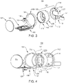
- FIG. 3 illustrates an exploded view of an alternate example of an adjustable mounting system 100, in accordance with an example of this disclosure.
- the wall mount 102 includes a primary (main wall-contacting) element 207 and an extending element 208.
- the extending element 208 can be attached to the primary element to enable the scaffold unit 106 to be located further away from the mounting surface (e.g., 200).
- Passing through scaffold unit 106 is a fastening element 125 which can be used to attach a teleconferencing device to the scaffold unit 106.
- the salient-connector portion 108 of the support component 104 comprises a flange 109.
- the wall mount 102 includes a cable-receiving element 111 that can be used to support one or more wires connected to a telepresence device.
- the cable-receiving element 111 can generally be made of some resiliently flexible material such as plastic.
- a cover 107 fits into the end of the salient section 110 to prevent the fasteners (202) from being visible during normal use of the system 100.
- the salient section 110 comprises a first section 110' joined to the planar face portion 114 and an extensor section 110" with a second planar face portion 210 having one or more second apertures formed therein.
- the first section 110' and the extensor section 110" are cylindrical and have matching circumferences 116.
- FIG. 4 illustrates another exploded view of an example of an adjustable mounting system 100, in accordance with an example of this disclosure.
- the system 100 includes a wall mount 102 having a salient section 110, and a planar face portion 114 having one or more apertures 112 formed therein. Each of the one or more apertures 112 are configured to receive a fastener to removably attach the wall mount 102 to a substantially flat surface, such as a wall 200 (see FIG. 2 ).
- the wall mount 102 includes a primary (main wall-contacting) element 207 and an extending element 208.
- the extending element 208 can be attached to the primary element to enable the scaffold unit 106 to be located further away from the mounting surface (e.g., 200).
- the salient-connector portion 108 of the support component 104 comprises a flange 109.
- Cover 107 fits into the end of the salient section 110 to prevent the fasteners (202) from being visible during normal use of the system 100.
- the salient section 110 comprises a first section 110' joined to the planar face portion 114 and an extensor section 110" with a second planar face portion 210 having one or more second apertures 212 formed therein. At least some of the apertures 212 of extending element 208 are aligned and/or congruent with the apertures 112.
- the system 100 also includes a support component 104 which is releasably connectable to the salient section 110.
- the support component 104 includes a scaffold unit 106 which is connected to a salient-connector portion 108.
- the salient-connector portion 108 is alternately operable in a fixed configuration (see FIG. 2 ) whereby the scaffold unit 106 is fastened to the salient section 110 of the wall mount 102, and an adjustment configuration (see FIG. 8 ) whereby the scaffold unit 106 is translatable with respect to a length 128 of the salient section 110 and rotatable about a circumference 116 of the salient section 110.
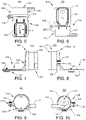
- FIG. 5 is a top plan view of an adjustable mounting system 100, in accordance with an example of this disclosure.
- the scaffold unit 106 includes an oblong aperture through which one or more fasteners (e.g., 125) can pass to attach a telepresence device to the scaffold unit 106.
- the salient-connector portion 108 is releasably connected to the extending element 208.
- the (underside) bottom 124 of the scaffold unit 106 is visible.
- FIG. 6 is a bottom plan view of an adjustable mounting system 100, in accordance with an example of this disclosure.
- the salient-connector portion 108 is releasably connected to the extending element 208.
- the (outer side) top 122 of the scaffold unit 106 is visible.
- FIG. 7 is a left-side view of an adjustable mounting system 100, in accordance with an example of this disclosure.
- the salient-connector portion 108 releasably connects the scaffold unit 106 to the salient section 110 of the wall mount 102.
- Passing through scaffold unit 106 is a fastening element 125 which can be used to attach a teleconferencing device to the scaffold unit 106.
- FIG. 8 is a right-side view of an adjustable mounting system 100, in accordance with an example of this disclosure.
- the salient-connector portion 108 is in an adjustment configuration 113 insofar as adjustment fastener 118 has not been used to close gap 120.
- the scaffold unit 106 is translatable along the length (128) of the salient section 110 and rotatable about a circumference (116) of the salient section 110.
- FIG. 9 is a front view of an adjustable mounting system 100, in accordance with an example of this disclosure.
- Cover 107 fits into the end of the wall mount to prevent fasteners (202) from being visible during normal use of the system 100.
- FIG. 10 is a rear view of an adjustable mounting system 100, in accordance with an example of this disclosure.
- apertures 112 in the planar face portion 114 of the wall mount 102 are clearly visible. Also visible is an additional opening 117 in the planar face portion 114.
- FIG. 11 is a perspective view of an adjustable mounting system 100, in accordance with an example of this disclosure.
- the (underside) bottom 124 of the scaffold unit 106 is oriented to receive a telepresence device or other equipment.
- FIG. 12 is a perspective view of an adjustable mounting system, in accordance with an example of this disclosure.
- the (outer side) top 122 of the scaffold unit 106 is oriented to receive a telepresence device or other equipment.
- FIG. 13 is a perspective view of an adjustable mounting system, in accordance with an example of this disclosure.
- the (underside) bottom 124 of the scaffold unit 106 is oriented to receive a telepresence device or other equipment.
- FIG. 14 is a perspective view of an adjustable mounting system, in accordance with an example of this disclosure.
- the (outer side) top 122 of the scaffold unit 106 is oriented to receive a telepresence device or other equipment.
- FIG. 15 is an exploded view of an adjustable mounting system 100, in accordance with an example of this disclosure.
- the wall mount 102 includes a platen portion 214 connected to the salient section 110 and the planar face portion 114.
- the salient section 110 is orthogonal to the planar face portion 114 and the platen portion 214.
- the platen portion 214 has a cable port 216 formed therein.
- the cable port 216 is configured to receive a removable cable port cover 219.
- the adjustable mounting system 100 also includes a wall plate 220 which can be attached to a wall. Fasteners (202) can then be used to fasten the wall mount 102 to the wall plate 220.
- FIG. 16 is a top plan view of the assembled adjustable mounting system 100 of FIG. 15 , in accordance with an example of this disclosure.
- the scaffold unit 106 is oriented to receive a teleconferencing device or other electronic device.
- FIG. 17 is a bottom plan view of the assembled adjustable mounting system 100 of FIG. 15 , in accordance with an example of this disclosure.
- FIG. 18 is a left-side view of the assembled adjustable mounting system 100 of FIG. 15 , in accordance with an example of this disclosure.
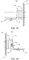
- FIG. 19 is a right-side view of the assembled adjustable mounting system 100 of FIG. 15 , in accordance with an example of this disclosure.
- FIG. 20 is a front view of the assembled adjustable mounting system 100 of FIG. 15 , in accordance with an example of this disclosure.
- FIG. 21 is a rear view of the assembled adjustable mounting system 100 of FIG. 15 , in accordance with an example of this disclosure. Cable port cover 219 is emplaced.
- FIG. 22 is a perspective view of an adjustable mounting system 100 of the assembled adjustable mounting system 100 of FIG. 15 , in accordance with an example of this disclosure.
- the scaffold unit 106 is oriented to receive a device on (inner side) bottom 124.
- FIG. 23 is a perspective view of an adjustable mounting system 100 of the assembled adjustable mounting system 100 of FIG. 15 , in accordance with an example of this disclosure.
- the support unit 104 has been rotated 180 degrees relative to the support unit's position in FIG. 22 .
- the scaffold unit 106 is therefore oriented to receive a device on (outer side) top 122.
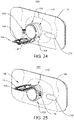
- FIG. 24 is a perspective view of an adjustable mounting system 100 of the assembled adjustable mounting system 100 of FIG. 15 , in accordance with an example of this disclosure.
- the system 100 in FIG. 24 differs from that in FIG. 22 in that in FIG. 24 the extending element 208 is present.
- the scaffold unit 106 is oriented to receive a device on (inner side) bottom 124.
- FIG. 25 is a perspective view of an adjustable mounting system 100, in accordance with an example of this disclosure.
- the system 100 in FIG. 25 differs from that in FIG. 23 in that in FIG. 25 the extending element 208 is present.
- the support unit 104 has been rotated 180 degrees relative to the support unit's position in FIG. 24 .
- the scaffold unit 106 is therefore oriented to receive a device on (outer side) top 122.
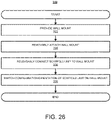
- FIG. 26 illustrates a method 300 for deploying an adjustable mounting system 100, in accordance with an example of this disclosure.
- the method 300 includes providing 302 a wall mount 102 comprising a salient section 110 connected to a first planar face portion having one or more first apertures 112 formed therein, each of the one or more first apertures 112 configured to receive a fastener 202.
- the method 300 includes removably attaching 304 the wall mount 102 to a planar surface 200 by driving a faster through each of the one or more first apertures 112 into a load-bearing material posterior to the planar surface 200, and then releasably connecting 306 a salient-connector portion 108 of a support device 104 to the salient section 110, the support device 104 having a scaffold unit 106 joined to the salient-connector portion 108.
- the method 300 includes switching 308 the salient-connector portion 108 from a fixed configuration (103) in which the scaffold unit 106 is fastened to the salient section 110 of the wall mount 102 to an adjustment configuration (113) in which the scaffold unit 106 is rotatable about a circumference 116 of the salient section 110 and translatable along a length 128 of the salient section 110.
- Examples of this disclosure include:
Landscapes
- Engineering & Computer Science (AREA)
- General Engineering & Computer Science (AREA)
- Mechanical Engineering (AREA)
- Multimedia (AREA)
- Signal Processing (AREA)
- Physics & Mathematics (AREA)
- General Physics & Mathematics (AREA)
- Connection Of Plates (AREA)
- Casings For Electric Apparatus (AREA)
Abstract
Description
- This application claims priority to
US Provisional Application No. 63/130,285, filed December 23, 2020 US Application No. 17/304,977, filed June 29, 2021 - This application relates generally to videoconferencing device mounting systems and relates particularly to systems for adjustably mounting a videoconferencing device to a wall or other similar surface.
- Systems and apparatuses exist for mounting cameras and similar devices to walls and similar surfaces. Such systems and apparatuses tend to be difficult to install, requiring multiple tools and a high degree of precision. Moreover, once they are installed, it is usually extremely challenging for a user to make precise adjustments based on the telepresence device being mounted. Thus, there is room for improvement in the art.
- An adjustable mounting system enables a telepresence device to be easily mounted to a wall. Once the mounting system is emplaced, the area of the mounting system to which the telepresence device will be connected can be adjusted for distance with respect to the wall as well as to ensure the scaffold unit is level - without the need for cumbersome tools.
-
FIG. 1 illustrates an adjustable mounting system for a telepresence device, in accordance with an example of this disclosure. -
FIG. 2 illustrates the adjustable mounting system ofFIG. 1 attached to a wall, in accordance with an example of this disclosure. -
FIG. 3 illustrates an exploded view of an alternate example of an adjustable mounting system, in accordance with an example of this disclosure. -
FIG. 4 illustrates another exploded view of an example of an adjustable mounting system, in accordance with an example of this disclosure. -
FIG. 5 is a top plan view of an adjustable mounting system, in accordance with an example of this disclosure. -
FIG. 6 is a bottom plan view of an adjustable mounting system, in accordance with an example of this disclosure. -
FIG. 7 is a left-side view of an adjustable mounting system, in accordance with an example of this disclosure. -
FIG. 8 is a right-side view of an adjustable mounting system, in accordance with an example of this disclosure. -
FIG. 9 is a front view of an adjustable mounting system, in accordance with an example of this disclosure. -
FIG. 10 is a rear view of an adjustable mounting system, in accordance with an example of this disclosure. -
FIG. 11 is a perspective view of an adjustable mounting system, in accordance with an example of this disclosure. -
FIG. 12 is a perspective view of an adjustable mounting system, in accordance with an example of this disclosure. -
FIG. 13 is a perspective view of an adjustable mounting system, in accordance with an example of this disclosure. -
FIG. 14 is a perspective view of an adjustable mounting system, in accordance with an example of this disclosure. -
FIG. 15 is an exploded view of an adjustable mounting system, in accordance with an example of this disclosure. -
FIG. 16 is a top plan view of an adjustable mounting system, in accordance with an example of this disclosure. -
FIG. 17 is a bottom plan view of an adjustable mounting system, in accordance with an example of this disclosure. -
FIG. 18 is a left-side view of an adjustable mounting system, in accordance with an example of this disclosure. -
FIG. 19 is a right-side view of an adjustable mounting system, in accordance with an example of this disclosure. -
FIG. 20 is a front view of an adjustable mounting system, in accordance with an example of this disclosure. -
FIG. 21 is a rear view of an adjustable mounting system, in accordance with an example of this disclosure. -
FIG. 22 is a perspective view of an adjustable mounting system, in accordance with an example of this disclosure. -
FIG. 23 is a perspective view of an adjustable mounting system, in accordance with an example of this disclosure. -
FIG. 24 is a perspective view of an adjustable mounting system, in accordance with an example of this disclosure. -
FIG. 25 is a perspective view of an adjustable mounting system, in accordance with an example of this disclosure. -
FIG. 26 illustrates a method for deploying an adjustable mounting system, in accordance with an example of this disclosure. - In the drawings and the description of the drawings herein, certain terminology is used for convenience only and is not to be taken as limiting the examples of the present disclosure. In the drawings and the description below, like numerals indicate like elements throughout.
-
FIG. 1 illustrates anadjustable mounting system 100 for a telepresence device, in accordance with an example of this disclosure. In the example shown inFIG. 1 , thesystem 100 has two primary components: awall mount 102 and asupport component 104. Thesupport component 104 has ascaffold unit 106 connected to a salient-connector portion 108. Thescaffold unit 106 can receive a telepresence device such as a camera or the poly studio X30 video bar™. The salient-connector portion 108 slides onto thesalient section 110 of thewall mount 102. Thewall mount 102 can be fastened to a wall by fasteners through holes (apertures 112) in theplanar face portion 114 of thewall mount 102. Theplanar face portion 114 is at least partially bounded bywalls 218 of thesalient section 110. The salient-connector portion 108 can slide along thesalient section 110 and around theouter circumference 116 of thesalient section 110 before the salient-connector portion 108 is tightened about thesalient section 110. An adjustment fastener 118 (e.g., a screw) can be used to shorten and/or close thegap 120 in the salient-connector portion 108 to keep thesupport component 104 from moving once emplaced. -
FIG. 2 illustrates theadjustable mounting system 100 ofFIG. 1 attached to a planar surface, (wall) 200. Thesalient section 110 of thesystem 100 is hollow in its interior (seeFIG. 1 ).Fasteners 202 are used to fasten theplanar face portion 114 of thesystem 100 to thewall 200. Anadjustment fastener 118 can be used to shorten thegap 120 in the salient-connector portion 108 to keep the salient-connector portion 108 from moving once thescaffold unit 106 ofsupport component 104 is positioned (by a user) as desired. Depending on the needs of the user, in some examples, a telepresence device can be attached to thetop 122 or thebottom 124 of thetongue 204 that forms thescaffold unit 106. It will be noted that although thesupport component 104 is positioned near a distal end of thesalient section 110 inFIG. 2 , thesupport component 104 can be moved along thelength 128 of thesalient section 110 when theadjustment fastener 118 is loosened. When theadjustment fastener 118 is loosened, as shown inFIG. 1 and FIG. 2 , the salient-connector portion 108 can be said to be in an adjustment configuration. Thesupport component 104 is releasably connected to theend 126 of thesalient portion 110 ofwall mount 102 which is distal from the mounting surface (wall) 200. The salient-connector portion 108 is in a fixed configuration 103 insofar as thescaffold unit 106 is releasably fastened to thesalient section 110 because the gap (120) has been closed by the adjustment fastener (118) -
FIG. 3 illustrates an exploded view of an alternate example of anadjustable mounting system 100, in accordance with an example of this disclosure. Thewall mount 102 includes a primary (main wall-contacting)element 207 and an extendingelement 208. The extendingelement 208 can be attached to the primary element to enable thescaffold unit 106 to be located further away from the mounting surface (e.g., 200). Passing throughscaffold unit 106 is afastening element 125 which can be used to attach a teleconferencing device to thescaffold unit 106. The salient-connector portion 108 of thesupport component 104 comprises aflange 109. InFIG. 3 , thewall mount 102 includes a cable-receivingelement 111 that can be used to support one or more wires connected to a telepresence device. The cable-receivingelement 111 can generally be made of some resiliently flexible material such as plastic. Acover 107 fits into the end of thesalient section 110 to prevent the fasteners (202) from being visible during normal use of thesystem 100. Thesalient section 110 comprises a first section 110' joined to theplanar face portion 114 and anextensor section 110" with a secondplanar face portion 210 having one or more second apertures formed therein. The first section 110' and theextensor section 110" are cylindrical and have matchingcircumferences 116. -
FIG. 4 illustrates another exploded view of an example of anadjustable mounting system 100, in accordance with an example of this disclosure. Thesystem 100 includes awall mount 102 having asalient section 110, and aplanar face portion 114 having one ormore apertures 112 formed therein. Each of the one ormore apertures 112 are configured to receive a fastener to removably attach thewall mount 102 to a substantially flat surface, such as a wall 200 (seeFIG. 2 ). Thewall mount 102 includes a primary (main wall-contacting)element 207 and an extendingelement 208. The extendingelement 208 can be attached to the primary element to enable thescaffold unit 106 to be located further away from the mounting surface (e.g., 200). Passing through ascaffold unit 106 is afastening element 125 which can be used to attach a teleconferencing device to thescaffold unit 106. The salient-connector portion 108 of thesupport component 104 comprises aflange 109. Cover 107 fits into the end of thesalient section 110 to prevent the fasteners (202) from being visible during normal use of thesystem 100. Thesalient section 110 comprises a first section 110' joined to theplanar face portion 114 and anextensor section 110" with a secondplanar face portion 210 having one or moresecond apertures 212 formed therein. At least some of theapertures 212 of extendingelement 208 are aligned and/or congruent with theapertures 112. - As discussed, the
system 100 also includes asupport component 104 which is releasably connectable to thesalient section 110. Again, thesupport component 104 includes ascaffold unit 106 which is connected to a salient-connector portion 108. The salient-connector portion 108 is alternately operable in a fixed configuration (seeFIG. 2 ) whereby thescaffold unit 106 is fastened to thesalient section 110 of thewall mount 102, and an adjustment configuration (seeFIG. 8 ) whereby thescaffold unit 106 is translatable with respect to alength 128 of thesalient section 110 and rotatable about acircumference 116 of thesalient section 110. -
FIG. 5 is a top plan view of anadjustable mounting system 100, in accordance with an example of this disclosure. Thescaffold unit 106 includes an oblong aperture through which one or more fasteners (e.g., 125) can pass to attach a telepresence device to thescaffold unit 106. The salient-connector portion 108 is releasably connected to the extendingelement 208. The (underside)bottom 124 of thescaffold unit 106 is visible. -
FIG. 6 is a bottom plan view of anadjustable mounting system 100, in accordance with an example of this disclosure. As inFIG. 5 , the salient-connector portion 108 is releasably connected to the extendingelement 208. The (outer side)top 122 of thescaffold unit 106 is visible. -
FIG. 7 is a left-side view of anadjustable mounting system 100, in accordance with an example of this disclosure. The salient-connector portion 108 releasably connects thescaffold unit 106 to thesalient section 110 of thewall mount 102. Passing throughscaffold unit 106 is afastening element 125 which can be used to attach a teleconferencing device to thescaffold unit 106. -
FIG. 8 is a right-side view of anadjustable mounting system 100, in accordance with an example of this disclosure. InFIG. 8 , the salient-connector portion 108 is in anadjustment configuration 113 insofar asadjustment fastener 118 has not been used to closegap 120. In the adjustment configuration, thescaffold unit 106 is translatable along the length (128) of thesalient section 110 and rotatable about a circumference (116) of thesalient section 110. -
FIG. 9 is a front view of anadjustable mounting system 100, in accordance with an example of this disclosure. Cover 107 fits into the end of the wall mount to prevent fasteners (202) from being visible during normal use of thesystem 100. -
FIG. 10 is a rear view of anadjustable mounting system 100, in accordance with an example of this disclosure. InFIG. 10 ,apertures 112 in theplanar face portion 114 of thewall mount 102 are clearly visible. Also visible is anadditional opening 117 in theplanar face portion 114. -
FIG. 11 is a perspective view of anadjustable mounting system 100, in accordance with an example of this disclosure. The (underside)bottom 124 of thescaffold unit 106 is oriented to receive a telepresence device or other equipment. -
FIG. 12 is a perspective view of an adjustable mounting system, in accordance with an example of this disclosure. The (outer side)top 122 of thescaffold unit 106 is oriented to receive a telepresence device or other equipment. -
FIG. 13 is a perspective view of an adjustable mounting system, in accordance with an example of this disclosure. As inFIG. 11 , the (underside)bottom 124 of thescaffold unit 106 is oriented to receive a telepresence device or other equipment. -
FIG. 14 is a perspective view of an adjustable mounting system, in accordance with an example of this disclosure. As inFIG. 12 , the (outer side)top 122 of thescaffold unit 106 is oriented to receive a telepresence device or other equipment. -
FIG. 15 is an exploded view of anadjustable mounting system 100, in accordance with an example of this disclosure. InFIG. 15 , thewall mount 102 includes aplaten portion 214 connected to thesalient section 110 and theplanar face portion 114. Thesalient section 110 is orthogonal to theplanar face portion 114 and theplaten portion 214. Theplaten portion 214 has acable port 216 formed therein. Thecable port 216 is configured to receive a removablecable port cover 219. Theadjustable mounting system 100 also includes awall plate 220 which can be attached to a wall. Fasteners (202) can then be used to fasten thewall mount 102 to thewall plate 220. -
FIG. 16 is a top plan view of the assembledadjustable mounting system 100 ofFIG. 15 , in accordance with an example of this disclosure. Thescaffold unit 106 is oriented to receive a teleconferencing device or other electronic device. -
FIG. 17 is a bottom plan view of the assembledadjustable mounting system 100 ofFIG. 15 , in accordance with an example of this disclosure. -
FIG. 18 is a left-side view of the assembledadjustable mounting system 100 ofFIG. 15 , in accordance with an example of this disclosure. -
FIG. 19 is a right-side view of the assembledadjustable mounting system 100 ofFIG. 15 , in accordance with an example of this disclosure. -
FIG. 20 is a front view of the assembledadjustable mounting system 100 ofFIG. 15 , in accordance with an example of this disclosure. -
FIG. 21 is a rear view of the assembledadjustable mounting system 100 ofFIG. 15 , in accordance with an example of this disclosure.Cable port cover 219 is emplaced. -
FIG. 22 is a perspective view of anadjustable mounting system 100 of the assembledadjustable mounting system 100 ofFIG. 15 , in accordance with an example of this disclosure. Thescaffold unit 106 is oriented to receive a device on (inner side)bottom 124. -
FIG. 23 is a perspective view of anadjustable mounting system 100 of the assembledadjustable mounting system 100 ofFIG. 15 , in accordance with an example of this disclosure. Thesupport unit 104 has been rotated 180 degrees relative to the support unit's position inFIG. 22 . Thescaffold unit 106 is therefore oriented to receive a device on (outer side)top 122. -
FIG. 24 is a perspective view of anadjustable mounting system 100 of the assembledadjustable mounting system 100 ofFIG. 15 , in accordance with an example of this disclosure. Thesystem 100 inFIG. 24 differs from that inFIG. 22 in that inFIG. 24 the extendingelement 208 is present. As inFIG. 22 , thescaffold unit 106 is oriented to receive a device on (inner side)bottom 124. -
FIG. 25 is a perspective view of anadjustable mounting system 100, in accordance with an example of this disclosure. Thesystem 100 inFIG. 25 differs from that inFIG. 23 in that inFIG. 25 the extendingelement 208 is present. As inFIG. 23 , thesupport unit 104 has been rotated 180 degrees relative to the support unit's position inFIG. 24 . Thescaffold unit 106 is therefore oriented to receive a device on (outer side)top 122. -
FIG. 26 illustrates amethod 300 for deploying anadjustable mounting system 100, in accordance with an example of this disclosure. Themethod 300 includes providing 302 awall mount 102 comprising asalient section 110 connected to a first planar face portion having one or morefirst apertures 112 formed therein, each of the one or morefirst apertures 112 configured to receive afastener 202. After providing 302 the wall mount, themethod 300 includes removably attaching 304 thewall mount 102 to aplanar surface 200 by driving a faster through each of the one or morefirst apertures 112 into a load-bearing material posterior to theplanar surface 200, and then releasably connecting 306 a salient-connector portion 108 of asupport device 104 to thesalient section 110, thesupport device 104 having ascaffold unit 106 joined to the salient-connector portion 108. Thereafter, themethod 300 includes switching 308 the salient-connector portion 108 from a fixed configuration (103) in which thescaffold unit 106 is fastened to thesalient section 110 of thewall mount 102 to an adjustment configuration (113) in which thescaffold unit 106 is rotatable about acircumference 116 of thesalient section 110 and translatable along alength 128 of thesalient section 110. - Examples of this disclosure include:
- 1. An
adjustable mounting system 100, comprising: awall mount 102 comprising asalient section 110 connected to aplanar face portion 114 having one or morefirst apertures 112 formed therein, each of the one or morefirst apertures 112 configured to receive afastener 202 to removably attach thewall mount 102 to aplanar surface 200; and asupport component 104 including ascaffold unit 106 and a salient-connector portion 108 joined thereto, the salient-connector portion 108 releasably connecting thesupport component 104 to thesalient section 110, wherein the salient-connector portion 108 is alternately operable in a fixed configuration (103) in which thescaffold unit 106 is releasably fastened to thesalient section 110 and an adjustment configuration (113) in which thescaffold unit 106 is translatable along alength 128 of thesalient section 110. - 2. The
adjustable mounting system 100 of example 1, wherein the salient-connector portion 108 is further alternately operable in the fixed configuration (103) in which thescaffold unit 106 is fastened to thesalient section 110 of thewall mount 102 and the adjustment configuration (113) in which thescaffold unit 106 is translatable along thelength 128 of thesalient section 110 and rotatable about acircumference 116 of thesalient section 110. - 3. The
adjustable mounting system 100 of example 1, wherein the salient-connector portion 108 comprises aflange 109. - 4. The
adjustable mounting system 100 of example 3, wherein theflange 109 includes a tightness-adjusting element operable to adjust a tightness of theflange 109 around thesalient section 110. - 5. The
adjustable mounting system 100 of example 1, wherein thesalient section 110 comprises a first section 110' joined to theplanar face portion 114 and anextensor section 110" with a secondplanar face portion 210 having one or moresecond apertures 212 formed therein, wherein at least one of the one or moresecond apertures 212 are congruent with at least one of the one or morefirst apertures 112. - 6. The
adjustable mounting system 100 of example 5, wherein the first section 110' and theextensor section 110" are cylindrical and have matchingcircumferences 116. - 7. The
adjustable mounting system 100 of example 1, thewall mount 102 further comprising a platen portion (214) connected to thesalient section 110 and theplanar face portion 114, wherein thesalient section 110 is orthogonal to theplanar face portion 114 and the platen portion (214). - 8. The
adjustable mounting system 100 of example 7, wherein the platen portion (214) has at least one cable port formed therein. - 9. The
adjustable mounting system 100 of example 8, wherein the cable port is configured to receive a removable cable port cover. - 10. The
adjustable mounting system 100 of example 1, wherein theplanar face portion 114 is at least partially bounded bywalls 218 of thesalient section 110. - 11. The
adjustable mounting system 100 of example 1, wherein theplanar surface 200 is formed by a metallic wall plate. - 12. The
adjustable mounting system 100 of example 1, wherein thescaffold unit 106 comprises afirst receiving area 122 operable to receive a supported device in a first configuration and asecond receiving area 124 operable to receive the supported device in a second configuration in which the salient-connector portion 108 is rotated from first configuration one hundred and eighty degrees about the salient portion. - 13. The
adjustable mounting system 100 of example 1, wherein thefastener 202 comprises a bolt, screw, or nail. - 14. A
method 300 for deploying anadjustable mounting system 100, comprising: providing 302 awall mount 102 comprising asalient section 110 connected to a first planar face portion having one or morefirst apertures 112 formed therein, each of the one or morefirst apertures 112 configured to receive afastener 202; removably attaching 304 thewall mount 102 to aplanar surface 200 by driving a faster through each of the one or morefirst apertures 112 into a load-bearing material posterior to theplanar surface 200; releasably connecting 306 a salient-connector portion 108 of asupport device 110 to thesalient section 110, thesupport device 110 having ascaffold unit 106 joined to the salient-connector portion 108; and switching 308 the salient-connector portion 108 from a fixed configuration (103) in which thescaffold unit 106 is fastened to thesalient section 110 of thewall mount 102 to an adjustment configuration (113) in which thescaffold unit 106 is rotatable about acircumference 116 of thesalient section 110 and translatable along alength 128 of thesalient section 110. - 15. The method for deploying the
adjustable mounting system 100 of example 14, wherein the salient-connector portion 108 comprises aflange 109. - 16. The method for deploying the
adjustable mounting system 100 of example 15, further comprising adjusting a tightness of theflange 109 around thesalient section 110. - 17. The method for deploying the
adjustable mounting system 100 of example 14, wherein removably attaching thewall mount 102 to theplanar surface 200 by driving thefastener 202 through each of the one or morefirst apertures 112 into the load-bearing material posterior to theplanar surface 200 comprises releasably attaching an extensor section to the load-bearing material by driving thefastener 202 through each of one or more second apertures of a second planar face portion of the extensor section congruent with the one or morefirst apertures 112 of the firstplanar face portion 114. - 18. The method for deploying the
adjustable mounting system 100 of example 14, wherein providing thewall mount 102 further comprises providing thewall mount 102 with a platen portion (214) connected to thesalient section 110 and the firstplanar face portion 114, thesalient section 110 orthogonal to the firstplanar face portion 114 and the platen portion (214). - 19. The method for deploying the
adjustable mounting system 100 example 18, wherein providing thewall mount 102 with the platen portion (214) comprises forming at least one cable port in the platen portion (214). - 20. The method for deploying the
adjustable mounting system 100 of example 14, further comprising rotating the salient-connector portion 108 from a first position in which a first receiving area of thescaffold unit 106 is operable to receive a supported device in a first configuration one hundred and eighty degrees about the salient portion to a second position in which a second receiving area of thescaffold unit 106 is operable to receive the supported device in a second configuration. - The various examples within this disclosure are provided by way of illustration and should not be construed to limit the scope of the disclosure. Various modifications and changes can be made to the principles and examples described herein without departing from the scope of the disclosure and without departing from the claims which follow.
-
- 1. An adjustable mounting system, comprising:
- a wall mount comprising a salient section connected to a planar face portion having one or more first apertures formed therein, each of the one or more first apertures configured to receive a fastener to removably attach the wall mount to a planar surface; and
- a support component including a scaffold unit and a salient-connector portion joined thereto, the salient-connector portion releasably connecting the support component to the salient section,
- wherein the salient-connector portion is alternately operable in a fixed configuration in which the scaffold unit is releasably fastened to the salient section and an adjustment configuration in which the scaffold unit is translatable along a length of the salient section.
- 2. The adjustable mounting system of clause 1, wherein the salient-connector portion is further alternately operable in the fixed configuration in which the scaffold unit is fastened to the salient section of the wall mount and the adjustment configuration in which the scaffold unit is translatable along the length of the salient section and rotatable about a circumference of the salient section.
- 3. The adjustable mounting system of clause 1 or clause 2, wherein the salient-connector portion comprises a flange.
- 4. The adjustable mounting system of clause 3, wherein the flange includes a tightness-adjusting element operable to adjust a tightness of the flange around the salient section.
- 5. The adjustable mounting system of any of the preceding clauses, wherein the salient section comprises a first section joined to the planar face portion and an extensor section with a second planar face portion having one or more second apertures formed therein, wherein at least one of the one or more second apertures are congruent with at least one of the one or more first apertures.
- 6. The adjustable mounting system of clause 5, wherein the salient section and the extensor section are cylindrical and have matching circumferences.
- 7. The adjustable mounting system of any of the preceding clauses, the wall mount further comprising a platen portion connected to the salient section and the planar face portion, wherein the salient section is orthogonal to the planar face portion and the platen portion.
- 8. The adjustable mounting system of clause 7, wherein the platen portion has at least one cable port formed therein.
- 9. The adjustable mounting system of clause 8, wherein the cable port is configured to receive a removable cable port cover.
- 10. The adjustable mounting system of any of the preceding clauses, wherein the planar face portion is at least partially bounded by walls of the salient section.
- 11. The adjustable mounting system of any of the preceding clauses, wherein the planar surface is formed by a metallic wall plate.
- 12. The adjustable mounting system of any of the preceding clauses, wherein the scaffold unit comprises a first receiving area operable to receive a supported device in a first configuration and a second receiving area operable to receive the supported device in a second configuration in which the salient-connector portion is rotated from the first configuration one hundred and eighty degrees about the salient portion.
- 13. The adjustable mounting system of any of the preceding clauses, wherein the fastener comprises a bolt, screw, or nail.
- 14. A method for deploying an adjustable mounting system, comprising:
- providing a wall mount comprising a salient section connected to a first planar face portion having one or more first apertures formed therein, each of the one or more first apertures configured to receive a fastener;
- removably attaching the wall mount to a planar surface by driving a fastener through each of the one or more first apertures into a load-bearing material posterior to the planar surface;
- releasably connecting a salient-connector portion of a support device to the salient section, the support device having a scaffold unit joined to the salient-connector portion; and
- switching the salient-connector portion from a fixed configuration in which the scaffold unit is fastened to the salient section of the wall mount to an adjustment configuration in which the scaffold unit is rotatable about a circumference of the salient section and translatable along a length of the salient section.
- 15. The method for deploying the adjustable mounting system of clause 14, wherein the salient-connector portion comprises a flange.
- 16. The method for deploying the adjustable mounting system of clause 15, further comprising adjusting a tightness of the flange around the salient section.
- 17. The method for deploying the adjustable mounting system of any of clauses 14 to 16, wherein removably attaching the wall mount to the planar surface by driving the fastener through each of the one or more first apertures into the load-bearing material posterior to the planar surface comprises releasably attaching an extensor section to the load-bearing material by driving the fastener through each of one or more second apertures of a second planar face portion of the extensor section congruent with the one or more first apertures of the first planar face portion.
- 18. The method for deploying the adjustable mounting system of any of clauses 14 to 17, wherein providing the wall mount further comprises providing the wall mount with a platen portion connected to the salient section and the first planar face portion, the salient section orthogonal to the first planar face portion and the platen portion.
- 19. The method for deploying the adjustable mounting system clause 18, wherein providing the wall mount with the platen portion comprises forming at least one cable port in the platen portion.
- 20. The method for deploying the adjustable mounting system of any of clauses 14 to 19, further comprising rotating the salient-connector portion from a first position in which a first receiving area of the scaffold unit is operable to receive a supported device in a first configuration one hundred and eighty degrees about the salient portion to a second position in which a second receiving area of the scaffold unit is operable to receive the supported device in a second configuration.
Claims (15)
- An adjustable mounting system, comprising:a wall mount comprising a salient section connected to a planar face portion having one or more first apertures formed therein, each of the one or more first apertures configured to receive a fastener to removably attach the wall mount to a planar surface; anda support component including a scaffold unit and a salient-connector portion joined thereto, the salient-connector portion releasably connecting the support component to the salient section,wherein the salient-connector portion is alternately operable in a fixed configuration in which the scaffold unit is releasably fastened to the salient section and an adjustment configuration in which the scaffold unit is translatable along a length of the salient section.
- The adjustable mounting system of claim 1, wherein the salient-connector portion is further alternately operable in the fixed configuration in which the scaffold unit is fastened to the salient section of the wall mount and the adjustment configuration in which the scaffold unit is translatable along the length of the salient section and rotatable about a circumference of the salient section.
- The adjustable mounting system of claim 1 or 2, wherein the salient-connector portion comprises a flange.
- The adjustable mounting system of any of the preceding claims, wherein the salient section comprises a first section joined to the planar face portion and an extensor section with a second planar face portion having one or more second apertures formed therein, wherein at least one of the one or more second apertures are congruent with at least one of the one or more first apertures.
- The adjustable mounting system of claim 4, wherein the salient section and the extensor section are cylindrical and have matching circumferences.
- The adjustable mounting system of any of the preceding claims, the wall mount further comprising a platen portion connected to the salient section and the planar face portion, wherein the salient section is orthogonal to the planar face portion and the platen portion.
- The adjustable mounting system of claim 6, wherein the planar face portion is at least partially bounded by walls of the salient section.
- The adjustable mounting system of any of the preceding claims, wherein the planar surface is formed by a metallic wall plate.
- The adjustable mounting system of any of the preceding claims, wherein the scaffold unit comprises a first receiving area operable to receive a supported device in a first configuration and a second receiving area operable to receive the supported device in a second configuration in which the salient-connector portion is rotated from first configuration one hundred and eighty degrees about the salient portion.
- The adjustable mounting system of any of the preceding claims, wherein the fastener comprises a bolt, screw, or nail.
- A method for deploying an adjustable mounting system, comprising:providing a wall mount comprising a salient section connected to a first planar face portion having one or more first apertures formed therein, each of the one or more first apertures configured to receive a fastener;removably attaching the wall mount to a planar surface by driving a fastener through each of the one or more first apertures into a load-bearing material posterior to the planar surface;releasably connecting a salient-connector portion of a support device to the salient section, the support device having a scaffold unit joined to the salient-connector portion; andswitching the salient-connector portion from a fixed configuration in which the scaffold unit is fastened to the salient section of the wall mount to an adjustment configuration in which the scaffold unit is rotatable about a circumference of the salient section and translatable along a length of the salient section.
- The method for deploying the adjustable mounting system of claim 11, wherein the salient-connector portion comprises a flange and wherein the method further comprises adjusting a tightness of the flange around the salient section.
- The method for deploying the adjustable mounting system of claim 11 or 12, wherein removably attaching the wall mount to the planar surface by driving the fastener through each of the one or more first apertures into the load-bearing material posterior to the planar surface comprises releasably attaching an extensor section to the load-bearing material by driving the fastener through each of one or more second apertures of a second planar face portion of the extensor section congruent with the one or more first apertures of the first planar face portion.
- The method for deploying the adjustable mounting system of claim 11, 12 or 13, wherein providing the wall mount further comprises providing the wall mount with a platen portion connected to the salient section and the first planar face portion, the salient section orthogonal to the first planar face portion and the platen portion.
- The method for deploying the adjustable mounting system of any of claims 11 through 14, further comprising rotating the salient-connector portion from a first position in which a first receiving area of the scaffold unit is operable to receive a supported device in a first configuration one hundred and eighty degrees about the salient portion to a second position in which a second receiving area of the scaffold unit is operable to receive the supported device in a second configuration.
Applications Claiming Priority (2)
| Application Number | Priority Date | Filing Date | Title |
|---|---|---|---|
| US202063130285P | 2020-12-23 | 2020-12-23 | |
| US17/304,977 US11800055B2 (en) | 2020-12-23 | 2021-06-29 | Adjustable mounting system for a telepresence device |
Publications (1)
| Publication Number | Publication Date |
|---|---|
| EP4020079A1 true EP4020079A1 (en) | 2022-06-29 |
Family
ID=78413812
Family Applications (1)
| Application Number | Title | Priority Date | Filing Date |
|---|---|---|---|
| EP21205010.8A Withdrawn EP4020079A1 (en) | 2020-12-23 | 2021-10-27 | Adjustable mounting system for a telepresence device |
Country Status (3)
| Country | Link |
|---|---|
| US (1) | US11800055B2 (en) |
| EP (1) | EP4020079A1 (en) |
| CN (1) | CN114666529A (en) |
Families Citing this family (1)
| Publication number | Priority date | Publication date | Assignee | Title |
|---|---|---|---|---|
| US20230332734A1 (en) * | 2022-02-09 | 2023-10-19 | Steven Wai-Tong Cheng | Device compatible mounting stand |
Citations (4)
| Publication number | Priority date | Publication date | Assignee | Title |
|---|---|---|---|---|
| US812660A (en) * | 1905-06-01 | 1906-02-13 | Marshall A Wood | Adjustable mirror-support. |
| US4074883A (en) * | 1976-03-31 | 1978-02-21 | Mastermount Corporation | Speaker mounting system |
| GB2476970A (en) * | 2010-01-18 | 2011-07-20 | Altron Comm Equipment Ltd | Camera support |
| US10827574B1 (en) * | 2015-07-27 | 2020-11-03 | Kuna Systems Corporation | Universal plate adapter |
Family Cites Families (17)
| Publication number | Priority date | Publication date | Assignee | Title |
|---|---|---|---|---|
| JP2808249B2 (en) * | 1994-11-10 | 1998-10-08 | 日本コントロール工業株式会社 | Camera stand |
| US20040223078A1 (en) * | 2003-05-09 | 2004-11-11 | Adam Zadok | Support for hand held video camera |
| US6991384B1 (en) * | 2004-05-27 | 2006-01-31 | Davis Robert C | Camera tripod rotating head |
| GB2459468A (en) * | 2008-04-23 | 2009-10-28 | Easi Rad Ltd | Wall mounting for central heating radiators |
| US20110205425A1 (en) * | 2009-02-26 | 2011-08-25 | Keith Brent Duncan | System, components, and methods for viewing documents and objects using a webcam |
| US8616789B1 (en) * | 2012-08-07 | 2013-12-31 | Steve Hutchison | Multi-adjustable camera mount |
| CN105208260B (en) * | 2014-06-17 | 2019-03-01 | 科友国际有限公司 | Multifunctional panoramic holder, camera system and camera positioning method |
| US20170160624A1 (en) * | 2015-12-04 | 2017-06-08 | Thomas Craig Boushell | Fully Articulated Camera Mount |
| US10012890B2 (en) * | 2016-04-29 | 2018-07-03 | Really Right Stuff, Llc | Panoramic camera support |
| US10588305B2 (en) * | 2016-07-20 | 2020-03-17 | Harold F. Larkin | Marine hub with interchangeable arms |
| US10386891B2 (en) * | 2017-01-02 | 2019-08-20 | iDevices, LLC | Systems and methods associated with smart devices |
| US10844997B1 (en) * | 2018-01-08 | 2020-11-24 | Amazon Technologies, Inc. | Device mounting assembly |
| US10725362B2 (en) * | 2018-05-05 | 2020-07-28 | Chapman/Leonard Studio Equipment, Inc. | Light weight two or three axis remote camera head |
| CN111721347A (en) * | 2019-03-20 | 2020-09-29 | 深圳市道通科技股份有限公司 | A calibration bracket |
| US10775683B1 (en) * | 2019-07-19 | 2020-09-15 | Richard C. Hallett | Multi-camera multi-position adapter |
| US11048151B2 (en) * | 2019-10-14 | 2021-06-29 | Arlo Technologies, Inc. | Mount for electronic device |
| US11531253B1 (en) * | 2021-10-20 | 2022-12-20 | Corner Design Co., Ltd. | Camera mount |
-
2021
- 2021-06-29 US US17/304,977 patent/US11800055B2/en active Active
- 2021-09-10 CN CN202111060938.9A patent/CN114666529A/en active Pending
- 2021-10-27 EP EP21205010.8A patent/EP4020079A1/en not_active Withdrawn
Patent Citations (4)
| Publication number | Priority date | Publication date | Assignee | Title |
|---|---|---|---|---|
| US812660A (en) * | 1905-06-01 | 1906-02-13 | Marshall A Wood | Adjustable mirror-support. |
| US4074883A (en) * | 1976-03-31 | 1978-02-21 | Mastermount Corporation | Speaker mounting system |
| GB2476970A (en) * | 2010-01-18 | 2011-07-20 | Altron Comm Equipment Ltd | Camera support |
| US10827574B1 (en) * | 2015-07-27 | 2020-11-03 | Kuna Systems Corporation | Universal plate adapter |
Also Published As
| Publication number | Publication date |
|---|---|
| US11800055B2 (en) | 2023-10-24 |
| CN114666529A (en) | 2022-06-24 |
| US20220201243A1 (en) | 2022-06-23 |
Similar Documents
| Publication | Publication Date | Title |
|---|---|---|
| US20050161575A1 (en) | Universal projector mount | |
| US4570887A (en) | Quick-connect mount for a camera and tripod | |
| US8201785B2 (en) | Camera positioning systems | |
| US7211798B2 (en) | Occupancy wall sensor | |
| US5124901A (en) | Sloping ceiling adapter for recessed lighting | |
| US9942639B2 (en) | Articulating, self retained on-wall bracket mounting system | |
| US10844997B1 (en) | Device mounting assembly | |
| EP3081840B1 (en) | Locking apparatus | |
| US10393310B2 (en) | Support assembly mountable on vertically disposed objects, such as televisions and video monitors | |
| US9075290B1 (en) | Mounting bracket for surveillance cameras | |
| US3365156A (en) | Electrical box assembly and mounting bracket | |
| US11048151B2 (en) | Mount for electronic device | |
| US8662763B2 (en) | L-shaped holder for optical devices | |
| US20100012799A1 (en) | Flat Panel Mounting System | |
| US20120199374A1 (en) | Universal stud or no stud mounted electrical boxes | |
| US20140064534A1 (en) | Loudspeaker system | |
| US11800055B2 (en) | Adjustable mounting system for a telepresence device | |
| US20180109050A1 (en) | Single-fastener mounting plate for electrical outlets | |
| US10408565B2 (en) | Accessory mount for rifle | |
| WO2019000201A1 (en) | Tripod head structure, tripod head having same and photographing assembly | |
| US2755053A (en) | Universal mounting devices for photographic apparatus | |
| US20190368655A1 (en) | Device mount | |
| US10914403B2 (en) | Adjustable mounting apparatus | |
| US11997452B2 (en) | Dual-axis swivel speaker mount assembly and mounting kit | |
| CN205278695U (en) | Supporting mechanism and use adjusting device and cloud platform of this supporting mechanism |
Legal Events
| Date | Code | Title | Description |
|---|---|---|---|
| PUAI | Public reference made under article 153(3) epc to a published international application that has entered the european phase |
Free format text: ORIGINAL CODE: 0009012 |
|
| STAA | Information on the status of an ep patent application or granted ep patent |
Free format text: STATUS: THE APPLICATION HAS BEEN PUBLISHED |
|
| AK | Designated contracting states |
Kind code of ref document: A1 Designated state(s): AL AT BE BG CH CY CZ DE DK EE ES FI FR GB GR HR HU IE IS IT LI LT LU LV MC MK MT NL NO PL PT RO RS SE SI SK SM TR |
|
| STAA | Information on the status of an ep patent application or granted ep patent |
Free format text: STATUS: REQUEST FOR EXAMINATION WAS MADE |
|
| 17P | Request for examination filed |
Effective date: 20221018 |
|
| RBV | Designated contracting states (corrected) |
Designated state(s): AL AT BE BG CH CY CZ DE DK EE ES FI FR GB GR HR HU IE IS IT LI LT LU LV MC MK MT NL NO PL PT RO RS SE SI SK SM TR |
|
| RAP1 | Party data changed (applicant data changed or rights of an application transferred) |
Owner name: HEWLETT-PACKARD DEVELOPMENT COMPANY L.P. |
|
| RAP1 | Party data changed (applicant data changed or rights of an application transferred) |
Owner name: HEWLETT-PACKARD DEVELOPMENT COMPANY, L.P. |
|
| STAA | Information on the status of an ep patent application or granted ep patent |
Free format text: STATUS: EXAMINATION IS IN PROGRESS |
|
| 17Q | First examination report despatched |
Effective date: 20240807 |
|
| STAA | Information on the status of an ep patent application or granted ep patent |
Free format text: STATUS: THE APPLICATION IS DEEMED TO BE WITHDRAWN |
|
| 18D | Application deemed to be withdrawn |
Effective date: 20241210 |