EP4020053A1 - Cultivation container and observation system - Google Patents
Cultivation container and observation system Download PDFInfo
- Publication number
- EP4020053A1 EP4020053A1 EP21216679.7A EP21216679A EP4020053A1 EP 4020053 A1 EP4020053 A1 EP 4020053A1 EP 21216679 A EP21216679 A EP 21216679A EP 4020053 A1 EP4020053 A1 EP 4020053A1
- Authority
- EP
- European Patent Office
- Prior art keywords
- waveguide substrate
- measurement light
- cultivation container
- surrounding wall
- cultivation
- Prior art date
- Legal status (The legal status is an assumption and is not a legal conclusion. Google has not performed a legal analysis and makes no representation as to the accuracy of the status listed.)
- Withdrawn
Links
Images





Classifications
-
- G—PHYSICS
- G02—OPTICS
- G02B—OPTICAL ELEMENTS, SYSTEMS OR APPARATUS
- G02B21/00—Microscopes
- G02B21/06—Means for illuminating specimens
- G02B21/08—Condensers
- G02B21/10—Condensers affording dark-field illumination
-
- G—PHYSICS
- G02—OPTICS
- G02B—OPTICAL ELEMENTS, SYSTEMS OR APPARATUS
- G02B21/00—Microscopes
- G02B21/06—Means for illuminating specimens
- G02B21/08—Condensers
- G02B21/082—Condensers for incident illumination only
- G02B21/084—Condensers for incident illumination only having annular illumination around the objective
-
- C—CHEMISTRY; METALLURGY
- C12—BIOCHEMISTRY; BEER; SPIRITS; WINE; VINEGAR; MICROBIOLOGY; ENZYMOLOGY; MUTATION OR GENETIC ENGINEERING
- C12M—APPARATUS FOR ENZYMOLOGY OR MICROBIOLOGY; APPARATUS FOR CULTURING MICROORGANISMS FOR PRODUCING BIOMASS, FOR GROWING CELLS OR FOR OBTAINING FERMENTATION OR METABOLIC PRODUCTS, i.e. BIOREACTORS OR FERMENTERS
- C12M31/00—Means for providing, directing, scattering or concentrating light
- C12M31/08—Means for providing, directing, scattering or concentrating light by conducting or reflecting elements located inside the reactor or in its structure
-
- C—CHEMISTRY; METALLURGY
- C12—BIOCHEMISTRY; BEER; SPIRITS; WINE; VINEGAR; MICROBIOLOGY; ENZYMOLOGY; MUTATION OR GENETIC ENGINEERING
- C12M—APPARATUS FOR ENZYMOLOGY OR MICROBIOLOGY; APPARATUS FOR CULTURING MICROORGANISMS FOR PRODUCING BIOMASS, FOR GROWING CELLS OR FOR OBTAINING FERMENTATION OR METABOLIC PRODUCTS, i.e. BIOREACTORS OR FERMENTERS
- C12M41/00—Means for regulation, monitoring, measurement or control, e.g. flow regulation
- C12M41/06—Means for regulation, monitoring, measurement or control, e.g. flow regulation of illumination
-
- G—PHYSICS
- G01—MEASURING; TESTING
- G01J—MEASUREMENT OF INTENSITY, VELOCITY, SPECTRAL CONTENT, POLARISATION, PHASE OR PULSE CHARACTERISTICS OF INFRARED, VISIBLE OR ULTRAVIOLET LIGHT; COLORIMETRY; RADIATION PYROMETRY
- G01J1/00—Photometry, e.g. photographic exposure meter
- G01J1/58—Photometry, e.g. photographic exposure meter using luminescence generated by light
-
- G—PHYSICS
- G02—OPTICS
- G02B—OPTICAL ELEMENTS, SYSTEMS OR APPARATUS
- G02B6/00—Light guides; Structural details of arrangements comprising light guides and other optical elements, e.g. couplings
- G02B6/0001—Light guides; Structural details of arrangements comprising light guides and other optical elements, e.g. couplings specially adapted for lighting devices or systems
- G02B6/0011—Light guides; Structural details of arrangements comprising light guides and other optical elements, e.g. couplings specially adapted for lighting devices or systems the light guides being planar or of plate-like form
-
- G—PHYSICS
- G02—OPTICS
- G02B—OPTICAL ELEMENTS, SYSTEMS OR APPARATUS
- G02B21/00—Microscopes
- G02B21/34—Microscope slides, e.g. mounting specimens on microscope slides
Definitions
- the present invention relates to a cultivation container and an observation system.
- the bright field observation is a method of irradiating a specimen with uniform illumination light (measurement light) and observing the light passing through the specimen.
- the dark field observation is a method of irradiating a specimen with measurement light in an oblique direction and observing scattered light or reflected light generated by the specimen.
- the present disclosure relates to a cultivation container comprising a waveguide substrate configured to totally reflect and guide measurement light incident from a side end surface of the waveguide substrate, and a surrounding wall standing upright on a top surface of the waveguide substrate and forming a cell cultivation space.
- the present disclosure relates toan observation system comprising the cultivation container as defined in any of the embodiments disclosed herein, and a light source configured to emit the measurement light incident on the waveguide substrate of the cultivation container.
- One or more embodiments provide a cultivation container and an observation system capable of observing a high contrast cell using an optical system.
- One or more embodiments relate to a cultivation container and an observation system capable of observing a high contrast cell using an optical system by making adherent cells glow locally. That is, one or more embodiments include a waveguide substrate configured toguide the measurement light while totally reflecting the light, and are carried out by making the adherent cell glow locally such that some of the measurement light locally enters the adherent cells in a cell cultivation space.
- the adherent cells cultivated in the cell cultivation space have a refractive index that is closer to that of a waveguide substrate in comparison with the case of air that is a gas and a cultivation liquid that is a liquid.
- the adherent cells when the adherent cells are present in the cell cultivation space, some of the measurement light guided into the waveguide substrate enters the adherent cells, and the measurement light is scattered in an interface between the adherent cell and the waveguide substrate, and in the adherent cell. Accordingly, the adherent cells glow locally.
- a phase contrast microscope is one method of observing such adherent cells with good contrast, and includes a phase contrast optical system having a phase film and a dimmer filter.
- a phase contrast microscope since an effect of a phase contrast is weakened or cannot be obtained in an edge portion of the solution of the cultivation container, a region where a phase contrast image with good contrast can be obtained is limited to the central portion of the container.
- Japanese Unexamined Patent Application Publication No. 2011-248216 and Japanese Unexamined Patent Application Publication No. 2018-081134 disclose a dark field optical system as a method of obtaining a high contrast image of an object.
- the dark field optical system is a technique of obtaining an image by causing measurement light to be incident on an observation object in an oblique direction with respect to an observation direction of a light receiving system and observing scattered light in the observation object. According to such a dark field optical system, it is possible to observe the adherent cell that is an object with good contrast regardless of the phase contrast image.
- the dark field optical system is applied to observation of a cell image in the cultivation container
- the measurement light entering the cultivation container in the oblique direction is transferred into the cultivation container and spreads over the entire cultivation container, the measurement light leaks from various areas of the cultivation container. Such leakage light may interfere with observation.
- a waveguide substrate configured to totally reflect and guide the measurement light that enters it from side end surfaces, and a surrounding wall standing upright on a top surface of the waveguide substrate and forming a cell cultivation space therein are provided. Accordingly, the measurement light is refracted and enters the cell cultivation space from the waveguide substrate to be scattered in the cell locally at a place where the adherent cells adhere to the waveguide substrate.
- an optical device such as a microscope, a camera with an equal magnification, or the like.
- FIG. 1 is a perspective view of a cultivation container 1 of a first embodiment.
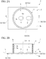
- FIG. 2A is a plan view of the cultivation container 1 of the first embodiment
- FIG. 2B is a cross-sectional view along line A-A of FIG. 2A .
- a direction in which a surrounding wall 3 protrudes from a waveguide substrate 2 is an upward direction.
- the upward direction set for the convenience of description does not necessarily coincide with an upward direction with respect to gravity.
- the cultivation container 1 is a container configured to perform cultivation of adherent cells X (cells that proliferate while adhering to the cultivation container 1), and it is possible to perform observation of the high contrast adherent cells X by introducing measurement light into the waveguide substrate 2 and using a light receiving system such as a camera or the like.
- the cultivation container 1 includes the waveguide substrate 2 and the surrounding wall 3.
- the waveguide substrate 2 is a plate-shaped member in which an upper surface 2a (a top surface) and a bottom surface 2b are disposed to face each other in parallel.
- the waveguide substrate 2 in one or more embodiments has a rectangular shape in a plan view. Further, a direction along a long side of the waveguide substrate 2 in a plan view is referred to as a leftward/rightward direction for the convenience of description, and a direction along a short side of the waveguide substrate 2 in a plan view is referred to as a forward/rearward direction for the convenience of description.
- the waveguide substrate 2 since a shape of the waveguide substrate 2 in a plan view is a rectangular shape, the waveguide substrate 2 has a left side end surface 2c1, a right side end surface 2c2, a front side end surface 2c3, and a rear side end surface 2c4, which are side end surfaces 2c.
- Each of the side end surfaces 2c is a plane.
- the left side end surface 2c1 is an incident end surface on which measurement light L is incident from the outside.
- the left side end surface 2c1 may be flattened (a surface roughness reduced) to be the same as one or more of the other side end surfaces 2c (the right side end surface 2c2, the front side end surface 2c3, and the rear side end surface 2c4) in order to minimize scattering when the measurement light L is incident.
- the upper surface 2a and the bottom surface 2b of the waveguide substrate 2 are planes. However, any one or both of the upper surface 2a and the bottom surface 2b may also be a curved surface or a concavo-convex surface.
- the upper surface 2a of the waveguide substrate 2 is a surface to which the adherent cells X are adhered. Further, a space surrounded by the surrounding wall 3 is a cell cultivation space K, and the adherent cells X are adhered to a partial region of the upper surface 2a facing the cell cultivation space K.
- the upper surface 2a of the waveguide substrate 2 is a connecting surface of the surrounding wall 3. In one or more embodiments, the surrounding wall 3 is connected to the waveguide substrate 2 through adhesion or fusion.
- the waveguide substrate 2 functions as a waveguide that guides the measurement light L incident from the left side end surface 2c1 that is an incident end surface toward the right side end surface 2c2 while being totally reflected therein.
- a laser beam is used as the measurement light L.
- a dimension from the upper surface 2a to the bottom surface 2b of the waveguide substrate 2 i.e., a thickness dimension
- the dimension can be set arbitrarily on the precondition that operability of the cultivation container 1 or strength required to support the surrounding wall 3 can be secured.
- the measurement light L may be a line laser beam that spreads in a plane in order to widen a measurable range. For this reason, for example, a widthwise dimension of the cultivation container 1 in the forward/rearward direction may be greater than a line length of the measurement light L in the forward/rearward direction.
- the waveguide substrate 2 that functions as a waveguide of the measurement light L in this way is formed of a transparent material with respect to the measurement light L, and for example, may be formed of glass or polystyrene.
- a laser beam with a peak wavelength of 520 nm is used as the measurement light L.
- the waveguide substrate 2 is formed of a material that can guide the measurement light L of the laser beam.
- a refractive index of the cell membrane of the adherent cell cultivated in the cultivation container 1 is about 1.46 to 1.6.
- a refractive index of the waveguide substrate 2 is closer to that of a cell membrane of the adherent cell than the cultivation liquid or air.
- a refractive index when the waveguide substrate 2 is formed of glass is 1.52
- a refractive index when the waveguide substrate 2 is formed of polystyrene is 1.59.
- the surrounding wall 3 is a cylindrical member centered on an axial center La, and stands upright on the upper surface 2a of the waveguide substrate 2.
- the surrounding wall 3 is oriented with respect to the waveguide substrate 2 such that the axial center La is parallel to a normal direction of the upper surface 2a of the waveguide substrate 2, a lower end is connected to the upper surface of the waveguide substrate 2, and an upper end is an open end.
- the surrounding wall 3 according to one or more embodiments is formed separately from the waveguide substrate 2, and then connected to the waveguide substrate 2.
- the surrounding wall 3 is connected to the waveguide substrate 2 via an adhesive agent, or connected to the waveguide substrate 2 through welding.
- the surrounding wall 3 can also be separated from the waveguide substrate 2. That is, in one or more embodiments, the surrounding wall 3 is detachably attached to the waveguide substrate 2.
- the surrounding wall 3 is detachably attached to the waveguide substrate 2 in this way, for example, it is also possible to use the waveguide substrate 2 without providing the surrounding wall 3.
- the surrounding wall 3 has a base part 3a and a shielding coating 3b (a shielding part).
- the base part 3a is formed of, for example, a resin, and may be formed of a different material from the waveguide substrate 2.
- the base part 3a is a main member that functions as a strength member of the surrounding wall 3, and connected to the waveguide substrate 2.
- the shielding coating 3b is a membrane member capable of shielding the measurement light L, and provided by covering the top surface of the base part 3a.
- the shielding coating 3b prevents the measurement light L entering the base part 3a of the surrounding wall 3 from the waveguide substrate 2 from leaking to the cell cultivation space K from the surrounding wall 3 by shielding the measurement light L.
- the shielding coating 3b is provided to cover the entire base part 3a except a connecting surface to the waveguide substrate 2.
- the shielding coating 3b can be provided only on the inner wall surface of the surrounding wall 3.
- a shielding part configured to prevent the measurement light L from entering the base part 3a may be provided between the base part 3a and the waveguide substrate 2.
- the shielding part prevents the measurement light L from entering the base part 3a from the waveguide substrate 2, and thus prevents the measurement light L from leaking from the surrounding wall 3 to the cell cultivation space K.
- a configuration in which the shielding coating 3b is not provided may be possible by providing a shielding part between the base part 3a and the waveguide substrate 2.
- the entire surrounding wall 3 may be formed of a colored resin or metal through which the measurement light L cannot pass, and may prevent the measurement light L from entering the base part 3a from the waveguide substrate 2.
- the surrounding wall 3 is not divided into the base part 3a and the shielding coating 3b as described above, and the surrounding wall 3 itself functions as a shielding part.
- the waveguide substrate 2 and the surrounding wall 3 are formed of different materials, for example, the waveguide substrate 2 and the surrounding wall 3 are separately formed and then joined to each other.
- the shielding coating 3b is coated on the base part 3a that was previously formed, and then the surrounding wall 3 is connected to the waveguide substrate 2 by an adhesive agent, welding, or the like.
- the base part 3a may be previously connected to the waveguide substrate 2, and then the shielding coating 3b may be formed on the top surface of the base part 3a.
- the base part 3a may be integrally formed of the same material as the waveguide substrate 2, and then the shielding coating 3b may be formed on the top surface of the base part 3a.
- an upper end surface 3c of the surrounding wall 3 is parallel to the upper surface 2a and the bottom surface 2b of the waveguide substrate 2. For this reason, the upper end surface 3c of the surrounding wall 3 also becomes horizontal when a posture of the waveguide substrate 2 is set such that the upper surface 2a and the bottom surface 2b of the waveguide substrate 2 become horizontal. As a result, a lid configured to close the cell cultivation space K from above can be easily placed on the upper end surface 3c of the surrounding wall 3.
- FIG. 3 is a schematic view when the measurement light L enters the cultivation container 1 of the above-mentioned embodiment.
- a difference between refractive indices of the waveguide substrate 2 and the air and cultivation liquid is great.
- the measurement light L entering the waveguide substrate 2 from the left side end surface 2c1 that is an incident end surface of the waveguide substrate 2 is guided toward the right side end surface 2c2 of the waveguide substrate 2 while being totally reflected by the upper surface 2a and the bottom surface 2b of the waveguide substrate 2.
- the measurement light L advances while totally being reflected in the waveguide substrate 2.
- the adherent cells X are present in the cell cultivation space K surrounded by the surrounding wall 3, since the refractive index of the adherent cells X is closer to the waveguide substrate 2 than the air or cultivation liquid, some of the measurement light L enters the adherent cells X.
- the measurement light L entering the adherent cells X in this way is scattered in the adherent cells X and the interface between the adherent cells X and the waveguide substrate 2.
- the measurement light L that advances through the waveguide substrate 2 is not visible, and the adherent cells X are locally visible.
- the adherent cells X can be visually recognized with good contrast by observing the adherent cells X from above using the cultivation container 1 according to one or more embodiments.
- the adherent cells X can be observed with good contrast with a microscope using an optical system.
- the measurement light L may be incident on the waveguide substrate 2 in a state in which an optical axis L1 is inclined with respect to the upper surface 2a and the bottom surface 2b of the waveguide substrate 2.
- an angle ⁇ between the upper surface 2a and the bottom surface 2b and the optical axis L1 of the measurement light L may be about 4°.
- the cultivation container 1 of the embodiment as described above includes the waveguide substrate 2 configured to totally reflect and guide the measurement light L incident from the left side end surface 2c1 thereinto, and the surrounding wall 3 standing on the upper surface 2a of the waveguide substrate 2 and forming the cell cultivation space K therein.
- the measurement light L is guided while being totally reflected in the waveguide substrate 2.
- the refractive index of the adherent cells X cultivated in the cell cultivation space K is close to that of the waveguide substrate 2 when compared with air, which is a gas, or cultivation liquid, which is liquid.
- air which is a gas, or cultivation liquid, which is liquid.
- the adherent cells X are present in the cell cultivation space K, some of the measurement light L guided into the waveguide substrate 2 enters the adherent cells X, and the measurement light L is scattered in the interface between the adherent cells X and the waveguide substrate 2 or in the adherent cells X. Accordingly, it is possible to make the adherent cells X glow locally.
- the cultivation container 1 according to one or more embodiments, it is possible to observe the high contrast adherent cells X using the optical system.
- the surrounding wall 3 includes the shielding coating 3b that shields the measurement light L. According to the cultivation container 1 of the above-mentioned embodiment, it is possible to prevent some of the measurement light L from leaking from the surrounding wall 3 to the cell cultivation space K. Accordingly, it is possible to observe the adherent cells X of the cell cultivation space K with better contrast.
- the surrounding wall 3 is formed of a material different from the waveguide substrate 2, and has the base part 3a detachably connected to the waveguide substrate 2 and the shielding coating 3b provided on the top surface of the base part 3a. According to the cultivation container 1 of the above-mentioned embodiment, since the surrounding wall 3 is separated from the waveguide substrate 2, selection of the material or the shape of the surrounding wall 3 can be designed separately from the waveguide substrate 2.
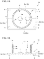
- FIG. 4A is a plan view of a cultivation container 1A according to one or more embodiments
- FIG. 4B is a cross-sectional view along line B-B of FIG. 4A
- the cultivation container 1A according to one or more embodiments includes a plurality of support legs 4 distributed on the bottom surface 2b of the waveguide substrate 2.
- a shape of the waveguide substrate 2 when seen in a plan view is a rectangular shape.
- the support legs 4 are provided at four corners of the waveguide substrate 2 having the rectangular shape when seen in a plan view.
- Each of the support legs 4 protrudes downward from the bottom surface 2b of the waveguide substrate 2, and has a columnar shape in one or more embodiments. Further, the support leg 4 may be a prismatic, cylindrical, or rectangular tubular shape.
- the cultivation container 1A according to one or more embodiments is installed on a floor surface, the support legs 4 directly abut the floor surface at lower surfaces thereof, and support the waveguide substrate 2 and the surrounding wall 3 from below.
- the support legs 4 abut the floor surface, it is possible to prevent the bottom surface 2b of the waveguide substrate 2 and the floor surface from coming in contact with each other.
- the cultivation container 1A since the bottom surface 2b of the waveguide substrate 2 can be prevented from coming into contact with other members, it is possible to minimize leakage of the measurement light L from the bottom surface 2b of the waveguide substrate 2.
- the support legs 4 may be formed of a colored resin into which the measurement light L does not enter.
- the support legs 4 may also be formed of a transparent material into which the measurement light L enters. In this case, since the measurement light L leaked from the support legs 4 is prevented from becoming stray light that obstructs observation of the adherent cells X, the top surface of the support legs 4 may be covered with the coating that shields the measurement light L.
- the cultivation container 1A includes the plurality of support legs 4 distributed on the bottom surface 2b of the waveguide substrate 2 and configured to support the waveguide substrate 2 from below. For this reason, it is possible to prevent leakage of the measurement light L to the other member as the bottom surface 2b of the waveguide substrate 2 comes into contact with the other member. For this reason, in the cultivation container 1A according to one or more embodiments, it is possible to prevent the observation of the adherent cells X from being hindered by the leakage of the measurement light L, and to prevent the efficiency of utilization of the measurement light L from being decreased by the leakage of the measurement light L.
- FIG. 5A is a plan view of a cultivation container 1B according to one or more embodiments
- FIG. 5B is a cross-sectional view along line C-C of FIG. 5A
- a reflecting plate 5 that abuts a right side end surface 2c2 of the waveguide substrate 2 from the outside is provided.
- the reflecting plate 5 may be referred to as a reflector or a reflecting part.
- the reflecting plate 5 is a member having a mirror surface capable of reflecting the measurement light L, which reflects the measurement light L guided in the waveguide substrate 2 and exit the waveguide substrate 2 from the right side end surface 2c2 of the waveguide substrate 2 to return the measurement light L into the waveguide substrate 2.
- the reflecting plate 5 is provided to cover the entire right side end surface 2c2 facing a left side end surface 2c1 that is an incident end surface of the waveguide substrate 2.
- the reflecting plate 5 may be provided to cover a front side end surface 2c3 or a rear side end surface 2c4.
- the measurement light L reflected by the reflecting plate 5 is guided through the waveguide substrate 2, and some of the measurement light L is incident on the adherent cells X and scattered.
- the right side end surface 2c2 and the reflecting surface of the reflecting plate 5 may be as smooth as the left side end surface 2c1, which is the incident end surface.
- a length dimension of the waveguide substrate 2 in the leftward/rightward direction may be set by the measurement light L reflected by the reflecting plate 5 and the measurement light L incident from the left side end surface 2c1 that is the incident end surface such that an interference fringe does not occur in the waveguide substrate 2.
- the cultivation container 1B includes the reflecting plate 5 provided at a position different from a position on which the measurement light L is incident (in one or more embodiments, the left side end surface 2c1) and configured to reflect the measurement light L. For this reason, when the reflecting plate 5 is provided, the measurement light L that has passed through the waveguide substrate 2 can be returned to the waveguide substrate 2 and used for observation of the adherent cells X. As a result, according to the cultivation container 1B according to one or more embodiments, efficiency of utilization of the measurement light L can be increased.
- the configuration including the plate-shaped reflecting plate 5 has been described.
- a reflecting part (reflector) having another shape may be installed instead of the reflecting plate 5.
- a reflecting part formed of a block body may also be provided to abut the right side end surface 2c2 and cover the right side end surface 2c2.
- FIG. 6A is a plan view of a cultivation container 1C according to one or more embodiments
- FIG. 6B is a cross-sectional view along line D-D of FIG. 6A .
- a surrounding wall 6 having a rectangular shape when seen in a plan view is provided.
- the surrounding wall 6 is a rectangular tubular member centered on the axial center La, and stands upright on the upper surface 2a of the waveguide substrate 2.
- the posture of the surrounding wall 6 is set with respect to the waveguide substrate 2 such that an axial center Lb is parallel to a normal direction of the upper surface 2a of the waveguide substrate 2, and the surrounding wall 6 has a lower end that is connected to the upper surface of the waveguide substrate 2, and an upper end that is an open end.
- the surrounding wall 6 has a rectangular shape when seen in a plan view.
- One side in the rectangular shape is parallel to the side end surface 2c of the waveguide substrate 2.
- one side of the surrounding wall 6 on the left side is parallel to the left side end surface 2c1 of the waveguide substrate 2.
- one side of the surrounding wall 6 on the right side is parallel to the right side end surface 2c2 of the waveguide substrate 2.
- one side of the surrounding wall 6 on the front side is parallel to the front side end surface 2c3 of the waveguide substrate 2.
- one side of the surrounding wall 6 on the rear side is parallel to the rear side end surface 2c4 of the waveguide substrate 2.
- the above-mentioned sides of the surrounding wall 6 may be inclined with respect to the side end surfaces 2c of the waveguide substrate 2.
- the above-mentioned surrounding wall 6 is formed separately from the waveguide substrate 2, and then, connected to the waveguide substrate 2.
- the above-mentioned surrounding wall 6 is connected to the waveguide substrate 2 via an adhesive agent or connected to the waveguide substrate 2 through welding.
- the surrounding wall 6 may be exfoliated from the waveguide substrate 2. That is, in one or more embodiments, the surrounding wall 6 is detachably attached to the waveguide substrate 2.
- the waveguide substrate 2 can also be used without providing the surrounding wall 6.
- the surrounding wall 6 has a base part 6a and a shielding coating 6b (a shielding part).
- the base part 6a is formed of, for example, a resin, and may be formed of a material different from the waveguide substrate 2.
- the above-mentioned base part 6a is a main member that functions as a strength member of the surrounding wall 6, and connected to the waveguide substrate 2.
- the shielding coating 6b is a membrane member capable of shielding the measurement light L, and provided by covering the top surface of the base part 6a.
- the shielding coating 6b prevents the measurement light L entering the base part 6a of the surrounding wall 6 from the waveguide substrate 2 from leaking from the surrounding wall 6 to the cell cultivation space K by shielding the measurement light L.
- the shielding coating 6b is provided to cover the entire base part 6a except a connecting surface to the waveguide substrate 2. However, since it is only necessary to prevent the measurement light L that has entered the surrounding wall 6 from leaking from the surrounding wall 6 to the cell cultivation space K, the shielding coating 6b may be provided only on the inner wall surface of the surrounding wall 6.
- the shielding part configured to prevent the measurement light L from entering the base part 6a may be provided between the base part 6a and the waveguide substrate 2.
- the shielding part prevents the measurement light L from entering the base part 6a from the waveguide substrate 2, and thus, prevents the measurement light L from leaking from the surrounding wall 6 to the cell cultivation space K.
- a configuration in which the above-mentioned shielding coating 6b is not provided may be possible by providing the shielding part between the base part 6a and the waveguide substrate 2.
- the entire surrounding wall 6 may be formed of a colored resin or metal through which the measurement light L does not pass to prevent the measurement light L from entering the base part 6a from the waveguide substrate 2.
- the surrounding wall 6 is not divided into the base part 6a and the shielding coating 6b as described above, and the surrounding wall 6 itself functions as a shielding part.
- the waveguide substrate 2 and the surrounding wall 6 are formed of different materials, for example, the waveguide substrate 2 and the surrounding wall 6 may be formed separately and then joined to each other.
- the shielding coating 6b is formed on the base part 6a that was previously formed, and then, the surrounding wall 6 is connected to the waveguide substrate 2 by an adhesive agent, welding, or the like.
- the base part 6a may be previously connected to the waveguide substrate 2, and then, the shielding coating 6b may be formed on the top surface of the base part 6a.
- the base part 6a may be formed integrally with the waveguide substrate 2 by the same material, and then, the shielding coating 6b may be formed on the top surface of the base part 6a.
- an upper end surface 6c of the surrounding wall 6 is parallel to the upper surface 2a and the bottom surface 2b of the waveguide substrate 2.
- the upper end surface 6c of the surrounding wall 6 is also horizontal by setting a posture of the waveguide substrate 2 such that the upper surface 2a and the bottom surface 2b of the waveguide substrate 2 are horizontal.
- a lid configured to close the cell cultivation space K from above can be easily placed on the upper end surface 6c of the surrounding wall 6.
- a shape of the surrounding wall 6 when seen in a plan view is a rectangular shape. For this reason, when a maximum dimension in the leftward/rightward direction is the same as a maximum dimension in the forward/rearward direction, it is possible to secure a wide range of the cell cultivation space K in comparison with the surrounding wall having a circular shape when seen in a plan view.
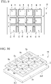
- FIG. 7 is a plan view of a cultivation container 1D according to one or more embodiments.
- the number of surrounding walls 3 are provided on the upper surface 2a of the waveguide substrate 2.
- the surrounding walls 3 are arranged in a lattice shape at equal intervals in the leftward/rightward direction and the forward/rearward direction.
- the cultivation container 1D has 12 cell cultivation spaces K.
- the number of the surrounding walls 3 is not limited to 12.
- a configuration including 24 surrounding walls 3 may be employed.
- all the surrounding walls 3 have the same protrusion amount (i.e., height dimension) from the upper surface 2a of the waveguide substrate 2. For this reason, it is possible to close upper end openings of all the surrounding walls 3 with a single plate-shaped lid.
- a size of the surrounding wall 3 is equal to that in the first embodiment, and a size of the waveguide substrate 2 is greater than that in the first embodiment.
- the plurality of surrounding walls 3 are provided on the single waveguide substrate 2. For this reason, the plurality of cell cultivation spaces K can be provided, and the adherent cells X can be divided and cultivated.
- FIG. 8 is an exploded perspective view of a cultivation container 1E according to one or more embodiments.
- the cultivation container 1E according to one or more embodimentsincludes a waveguide substrate 2 and a surrounding wall 7.
- the surrounding wall 7 has a plurality of accommodating parts 7a having a circular shape when seen in a plan view.
- the accommodating parts 7a are arranged in a lattice shape at equal intervals in the leftward/rightward direction and the forward/rearward direction.
- four accommodating parts 7a are arranged in the leftward/rightward direction, three accommodating parts 7a are arranged in the forward/rearward direction, and thus, the total 12 accommodating parts 7a are provided with respect to the surrounding wall 7.
- the number of the accommodating parts 7a is not limited to 12.
- a configuration including 24 accommodating parts 7a may be employed.
- the accommodating parts 7a form the cell cultivation space K in a state in which the surrounding wall 7 is connected to the upper surface of the waveguide substrate 2. That is, the inside of the accommodating parts 7a is the cell cultivation space K.
- the cell cultivation space K is formed in a part of the upper surface 2a of the waveguide substrate 2 by being surrounded by the surrounding wall 7.
- the surrounding wall 7 is formed of a material into which the measurement light L cannot enter. In this way, when the surrounding wall 7 is formed of the material into which the measurement light L cannot enter, it is possible to prevent the measurement light L from entering the surrounding wall 7 from the waveguide substrate 2 and prevent the light that interferes with observation of the adherent cells X from leaking from the surrounding wall 7.
- the surrounding wall 7 may be configured to include a base part that is a strength member, and a shielding coating configured to cover a top surface of the base part and shield the measurement light L. According to the above-mentioned configuration, even when some of the measurement light L enters the base part from the waveguide substrate 2, it is possible to prevent the measurement light that has entered the base part from leaking to the cell cultivation space K by being blocked by the shielding coating.
- the surrounding wall 7 includes the plurality of accommodating parts 7a that each forms the cell cultivation space K. For this reason, when the single surrounding wall 7 is adhered to the waveguide substrate 2, the number of cell cultivation spaces K can be formed at once.
- FIG. 9 is a plan view of a cultivation container IF according to one or more embodiments.
- the number of surrounding walls 6 are provided on the upper surface 2a of the waveguide substrate 2.
- the surrounding walls 6 are arranged in a lattice shape at equal intervals in the leftward/rightward direction and the forward/rearward direction.
- the cultivation container IF has 12 cell cultivation spaces K.
- the number of the surrounding walls 6 is not limited to 12. For example, a configuration including 24 surrounding walls 6 may be employed.
- all the surrounding walls 6 have the same protrusion amount (i.e., height dimension) from the upper surface 2a of the waveguide substrate 2. For this reason, it is possible to close upper end openings of all the surrounding walls 6 with a single plate-shaped lid.
- a size of the surrounding wall 6 is the same as in the first embodiment, and a size of the waveguide substrate 2 is greater than that in the first embodiment.
- the plurality of surrounding walls 6 are provided on the single waveguide substrate 2. For this reason, the plurality of cell cultivation spaces K can be provided, and the adherent cells X can be divided and cultivated.
- a shape of the surrounding wall 6 when seen in a plan view is a rectangular shape. For this reason, when a maximum dimension in the leftward/rightward direction and a maximum dimension in the forward/rearward direction are the same, the cell cultivation space K can be widely secured in comparison with the surrounding wall having a circular shape when seen in a plan view. Accordingly, the cell cultivation spaces K can be widely secured on the upper surface 2a of the single waveguide substrate 2.
- FIG. 10 is an exploded perspective view of a cultivation container 1G according to one or more embodiments.
- the cultivation container 1G according to one or more embodiments includes a waveguide substrate 2 and a surrounding wall 8.
- the surrounding wall 8 in one or more embodiments has a plurality of accommodating parts 8a having a rectangular shape when seen in a plan view.
- the accommodating parts 8a are arranged in a lattice shape at equal intervals in the leftward/rightward direction and the forward/rearward direction.
- four accommodating parts 8a are arranged in the leftward/rightward direction, three accommodating parts 8a are arranged in the forward/rearward direction, and thus, the total 12 accommodating parts 8a are provided with respect to the surrounding wall 8.
- the number of the accommodating parts 8a is not limited to 12.
- a configuration including 24 accommodating parts 8a may be employed.
- the accommodating parts 8a form the cell cultivation space K in a state in which the surrounding wall 8 is connected to the upper surface of the waveguide substrate 2. That is, the inside of the accommodating parts 8a is the cell cultivation space K. In this way, even in one or more embodiments, the cell cultivation space K is formed on a part of the upper surface 2a of the waveguide substrate 2 by being surrounded by the surrounding wall 8.
- the surrounding wall 8 is formed of a material into which the measurement light L cannot enter.
- the surrounding wall 8 is formed of the material into which the measurement light L cannot enter in this way, it is possible to prevent the measurement light L from entering the surrounding wall 8 from the waveguide substrate 2 and prevent the light that interferes with observation of the adherent cells X from leaking from the surrounding wall 8.
- the surrounding wall 8 may be configured to include a base part that is a strength member, and a shielding coating configured to cover a top surface of the base part and configured to shield the measurement light L. According to the above-mentioned configuration, even when some of the measurement light L enters the base part from the waveguide substrate 2, it is possible to prevent the measurement light that has entered the base part from leaking to the cell cultivation space K by being shielded by the shielding coating.
- the surrounding wall 8 includes the plurality of accommodating parts 8a that each forms the cell cultivation space K. For this reason, when the single the surrounding wall 7 is adhered to the waveguide substrate 2, the number of cell cultivation spaces K can be formed at once.
- a shape of each of the accommodating parts 8a when seen in a plan view is a rectangular shape.
- the cell cultivation space K can be widely secured. Accordingly, the cell cultivation space K can be widely secured on the upper surface 2a of the single waveguide substrate 2.
- FIG. 11 is a schematic view showing a schematic configuration of an observation system 10 according to one or more embodiments.
- the observation system 10 according to one or more embodiments includes a cultivation container 1 and a light source 11.
- the light source 11 is a laser beam emitting device configured to emit the measurement light L. As shown in FIG. 11 , the light source 11 is disposed aside the cultivation container 1 to face the left side end surface 2c1 of the waveguide substrate 2. The above-mentioned light source 11 emits the measurement light L such that the optical axis L1 of the measurement light L is inclined with respect to the upper surface 2a and the bottom surface 2b of the waveguide substrate 2 within a range that satisfies a condition in which the measurement light L is totally reflected in the waveguide substrate 2.
- the light source 11 configured to emit the measurement light L is provided.
- An output or the like with respect to the light source 11 can be previously set such that the measurement light L appropriate for observation of the adherent cells X is emitted. For this reason, adjustment of the measurement light L can be completed for a short time.
- the upper surface 2a and the bottom surface 2b of the waveguide substrate 2 of the cultivation container 1 are planar, and the light source 11 is disposed such that the optical axis L1 of the measurement light L incident on the left side end surface 2c1 of the waveguide substrate 2 is inclined with respect to the upper surface 2a and the bottom surface 2b of the waveguide substrate 2. For this reason, the number of reflections of the measurement light L with the upper surface 2a in the waveguide substrate 2 can be increased, and chances of causing the measurement light L to be incident on the adherent cells X can be increased.
- a stage configured to define an installation position of the cultivation container 1 may be provided, and a configuration of directly or indirectly fixing the light source 11 to the stage may be possible.
- the cultivation container 1 can be easily placed at a position that is defined in advance, and further, a posture of the light source 11 with respect to the placed cultivation container 1 can be accurately determined as a posture appropriate for observation. For this reason, for example, the measurement light L can be reliably emitted such that the optical axis L1 forms a desired inclination angle with respect to the upper surface 2a and the bottom surface 2b of the waveguide substrate 2 of the cultivation container 1.
- the configuration including the cultivation container 1 has been described. However, one or more embodiments are not limited thereto.
- a configuration including the cultivation container 1A of the second embodiment, the cultivation container 1B of the third embodiment, the cultivation container 1C of the fourth embodiment, the cultivation container 1D of the fifth embodiment, the cultivation container 1E of the sixth embodiment, the cultivation container IF of the seventh embodiment, or the cultivation container 1G of the eighth embodiment, instead of the cultivation container 1, may be employed.
- FIG. 12 is a schematic view showing a schematic configuration of an observation system 20 according to one or more embodiments.
- the observation system 20 includes a cultivation container 1, a light source 11, and an optical system 21 (an observation part).
- the optical system 21 is an optical system that can enlarge and observe the entirety or a part of the cell cultivation space K, and is disposed above the cultivation container 1.
- the optical system 21 receives the measurement light L dispersed in the adherent cells X, and enables observation by observer or imaging by a camera or the like due to formation of an image.
- the optical system 21 is not limited in the installation position or the imaging direction, with the precondition that the adherent cells X in the cultivation container 1 can be observed. That is, the optical system 21 can be installed at various positions with respect to the cultivation container 1 and can image the adherent cells X in various directions.
- the observation system 20 includes the optical system 21. For this reason, it is possible to observe the adherent cells X cultivated in the cell cultivation space K without using an external optical system.
- measurement light is totally reflected and guided in the waveguide substrate.
- the adherent cells cultivated in the cell cultivation space have a refractive index close to that of the waveguide substrate in comparison with air that is a gas and a cultivation liquid that is a liquid. For this reason, when the adherent cells are present in the cell cultivation space, some of the measurement light guided in the waveguide substrate is refracted and incident in the adherent cells, and the measurement light is scattered in the interface between the adherent cells and the waveguide substrate or in the adherent cells. Accordingly, the adherent cells can locally glow. As a result, according to one or more embodiments, it is possible to observe high contrast cells using an optical system.
- the term "configured” is used to describe a component, unit or part of a device includes hardware and/or software that is constructed and/or programmed to carry out the function according to one or more embodiments.
- unit is used to describe a component, unit or part of a hardware and/or software that is constructed and/or programmed to carry out the function according to one or more embodiments.
- Typical examples of the hardware may include, but are not limited to, a device and a circuit.
Landscapes
- Physics & Mathematics (AREA)
- Chemical & Material Sciences (AREA)
- General Physics & Mathematics (AREA)
- Wood Science & Technology (AREA)
- Organic Chemistry (AREA)
- Bioinformatics & Cheminformatics (AREA)
- Engineering & Computer Science (AREA)
- Health & Medical Sciences (AREA)
- Life Sciences & Earth Sciences (AREA)
- Zoology (AREA)
- Optics & Photonics (AREA)
- Analytical Chemistry (AREA)
- Microbiology (AREA)
- General Engineering & Computer Science (AREA)
- General Health & Medical Sciences (AREA)
- Genetics & Genomics (AREA)
- Biochemistry (AREA)
- Sustainable Development (AREA)
- Biotechnology (AREA)
- Biomedical Technology (AREA)
- Spectroscopy & Molecular Physics (AREA)
- Apparatus Associated With Microorganisms And Enzymes (AREA)
Abstract
Description
- The present invention relates to a cultivation container and an observation system.
- Priority is claimed on
Japanese Patent Application No. 2020-216121, filed on December 25, 2020 - As a basic observation method of observing a specimen, bright field observation and dark field observation are exemplified. The bright field observation is a method of irradiating a specimen with uniform illumination light (measurement light) and observing the light passing through the specimen. On the other hand, the dark field observation is a method of irradiating a specimen with measurement light in an oblique direction and observing scattered light or reflected light generated by the specimen. When the bright field observation is performed on an adherent cell (a cell that proliferates while adhering to a cultivation container) during cultivation in the cultivation container, a contrast becomes low. For this reason, when the adherent cell is observed, the dark field observation may be performed. Further,
Japanese Unexamined Patent Application Publication No. 2011-248216 Japanese Unexamined Patent Application Publication No. 2018-081134 - Incidentally, for example, when the dark field observation of the cell in the cultivation container is performed using the dark field optical system disclosed in
Japanese Unexamined Patent Application Publication No. 2011-248216 Japanese Unexamined Patent Application Publication No. 2018-081134 - According to one aspect, the present disclosure relates to a cultivation container comprising a waveguide substrate configured to totally reflect and guide measurement light incident from a side end surface of the waveguide substrate, and a surrounding wall standing upright on a top surface of the waveguide substrate and forming a cell cultivation space.
- Further embodiments of the cultivation container are defined in the
dependent claims 2 to 9 - According to a further aspect, the present disclosure relates toan observation system comprising the cultivation container as defined in any of the embodiments disclosed herein, and a light source configured to emit the measurement light incident on the waveguide substrate of the cultivation container.
- Further embodiments of the observation system are defined in the
dependent claims 11 to 20. - Further features and aspects of the present disclosure will become apparent from the following detailed description of exemplary embodiments with reference to the attached drawings.
-
-
FIG. 1 is a perspective view of a cultivation container according to a first embodiment. -
FIG. 2A is a plan view of the cultivation container of the first embodiment. -
FIG. 2B is a cross-sectional view along line A-A ofFIG. 2A . -
FIG. 3 is a schematic view of a case in which measurement light is incident into the cultivation container of the first embodiment. -
FIG. 4A is a plan view of a cultivation container according to a second embodiment. -
FIG. 4B is a cross-sectional view along line B-B ofFIG. 4A . -
FIG. 5A is a plan view of a cultivation container according to a third embodiment. -
FIG. 5B is a cross-sectional view along line C-C ofFIG. 5A . -
FIG. 6A is a plan view of a cultivation container according to a fourth embodiment. -
FIG. 6B is a cross-sectional view along line D-D ofFIG. 6A . -
FIG. 7 is a plan view of a cultivation container according to a fifth embodiment. -
FIG. 8 is an exploded perspective view of a cultivation container according to a sixth embodiment. -
FIG. 9 is a plan view of a cultivation container according to a seventh embodiment. -
FIG. 10 is an exploded perspective view of a cultivation container according to an eighth embodiment. -
FIG. 11 is a schematic view showing a schematic configuration of an observation system according to a ninth embodiment. -
FIG. 12 is a schematic view showing a schematic configuration of an observation system according to a tenth embodiment. - Embodiments of the present invention will be described herein with reference to the drawings.
- One or more embodiments provide a cultivation container and an observation system capable of observing a high contrast cell using an optical system.
- Hereinafter, a cultivation container and an observation system according one or more embodiments will be described with reference to the accompanying drawings.
- One or more embodiments relate to a cultivation container and an observation system capable of observing a high contrast cell using an optical system by making adherent cells glow locally. That is, one or more embodiments include a waveguide substrate configured toguide the measurement light while totally reflecting the light, and are carried out by making the adherent cell glow locally such that some of the measurement light locally enters the adherent cells in a cell cultivation space. The adherent cells cultivated in the cell cultivation space have a refractive index that is closer to that of a waveguide substrate in comparison with the case of air that is a gas and a cultivation liquid that is a liquid. For this reason, when the adherent cells are present in the cell cultivation space, some of the measurement light guided into the waveguide substrate enters the adherent cells, and the measurement light is scattered in an interface between the adherent cell and the waveguide substrate, and in the adherent cell. Accordingly, the adherent cells glow locally.
- When the adherent cells in the cultivation container are observed during cultivation, in observation in a bright field in which light passing through an object is observed, a contrast is decreased. For this reason, in observation of the adherent cells in the bright field, a boundary between the cells becomes unclear, which is not suitable for observing unstained cells. A phase contrast microscope is one method of observing such adherent cells with good contrast, and includes a phase contrast optical system having a phase film and a dimmer filter. However, in the phase contrast microscope, since an effect of a phase contrast is weakened or cannot be obtained in an edge portion of the solution of the cultivation container, a region where a phase contrast image with good contrast can be obtained is limited to the central portion of the container.
-
Japanese Unexamined Patent Application Publication No. 2011-248216 Japanese Unexamined Patent Application Publication No. 2018-081134 - In one or more embodiments, a waveguide substrate configured to totally reflect and guide the measurement light that enters it from side end surfaces, and a surrounding wall standing upright on a top surface of the waveguide substrate and forming a cell cultivation space therein are provided. Accordingly, the measurement light is refracted and enters the cell cultivation space from the waveguide substrate to be scattered in the cell locally at a place where the adherent cells adhere to the waveguide substrate. As a result, according to the one or more embodiments, it is possible to observe adherent cell with good contrast using an optical device such as a microscope, a camera with an equal magnification, or the like.
-
FIG. 1 is a perspective view of acultivation container 1 of a first embodiment. In addition,FIG. 2A is a plan view of thecultivation container 1 of the first embodiment, andFIG. 2B is a cross-sectional view along line A-A ofFIG. 2A . Further, in the following description, for the convenience of description, a direction in which asurrounding wall 3 protrudes from awaveguide substrate 2 is an upward direction. However, in a placement posture of thecultivation container 1 upon storage or the like, the upward direction set for the convenience of description does not necessarily coincide with an upward direction with respect to gravity. - The
cultivation container 1 according to one or more embodiments is a container configured to perform cultivation of adherent cells X (cells that proliferate while adhering to the cultivation container 1), and it is possible to perform observation of the high contrast adherent cells X by introducing measurement light into thewaveguide substrate 2 and using a light receiving system such as a camera or the like. As shown inFIG. 1 ,FIG. 2A, and FIG. 2B , thecultivation container 1 includes thewaveguide substrate 2 and the surroundingwall 3. - The
waveguide substrate 2 is a plate-shaped member in which anupper surface 2a (a top surface) and abottom surface 2b are disposed to face each other in parallel. Thewaveguide substrate 2 in one or more embodiments has a rectangular shape in a plan view. Further, a direction along a long side of thewaveguide substrate 2 in a plan view is referred to as a leftward/rightward direction for the convenience of description, and a direction along a short side of thewaveguide substrate 2 in a plan view is referred to as a forward/rearward direction for the convenience of description. - In one or more embodiments, since a shape of the
waveguide substrate 2 in a plan view is a rectangular shape, thewaveguide substrate 2 has a left side end surface 2c1, a right side end surface 2c2, a front side end surface 2c3, and a rear side end surface 2c4, which are side end surfaces 2c. Each of the side end surfaces 2c is a plane. - In one or more embodiments, the left side end surface 2c1 is an incident end surface on which measurement light L is incident from the outside. The left side end surface 2c1 may be flattened (a surface roughness reduced) to be the same as one or more of the other side end surfaces 2c (the right side end surface 2c2, the front side end surface 2c3, and the rear side end surface 2c4) in order to minimize scattering when the measurement light L is incident.
- In addition, in one or more embodiments, the
upper surface 2a and thebottom surface 2b of thewaveguide substrate 2 are planes. However, any one or both of theupper surface 2a and thebottom surface 2b may also be a curved surface or a concavo-convex surface. Theupper surface 2a of thewaveguide substrate 2 is a surface to which the adherent cells X are adhered. Further, a space surrounded by the surroundingwall 3 is a cell cultivation space K, and the adherent cells X are adhered to a partial region of theupper surface 2a facing the cell cultivation space K. In addition, theupper surface 2a of thewaveguide substrate 2 is a connecting surface of the surroundingwall 3. In one or more embodiments, the surroundingwall 3 is connected to thewaveguide substrate 2 through adhesion or fusion. - The
waveguide substrate 2 functions as a waveguide that guides the measurement light L incident from the left side end surface 2c1 that is an incident end surface toward the right side end surface 2c2 while being totally reflected therein. A laser beam is used as the measurement light L. When a dimension from theupper surface 2a to thebottom surface 2b of the waveguide substrate 2 (i.e., a thickness dimension) is a range in which the entire the measurement light L is able to be incident, the dimension can be set arbitrarily on the precondition that operability of thecultivation container 1 or strength required to support the surroundingwall 3 can be secured. - In addition, the measurement light L may be a line laser beam that spreads in a plane in order to widen a measurable range. For this reason, for example, a widthwise dimension of the
cultivation container 1 in the forward/rearward direction may be greater than a line length of the measurement light L in the forward/rearward direction. - The
waveguide substrate 2 that functions as a waveguide of the measurement light L in this way is formed of a transparent material with respect to the measurement light L, and for example, may be formed of glass or polystyrene. For example, a laser beam with a peak wavelength of 520 nm is used as the measurement light L. For this reason, thewaveguide substrate 2 is formed of a material that can guide the measurement light L of the laser beam. - Further, a refractive index of the cell membrane of the adherent cell cultivated in the
cultivation container 1 is about 1.46 to 1.6. On the other hand, a refractive index of thewaveguide substrate 2 is closer to that of a cell membrane of the adherent cell than the cultivation liquid or air. For example, a refractive index when thewaveguide substrate 2 is formed of glass is 1.52, and a refractive index when thewaveguide substrate 2 is formed of polystyrene is 1.59. - The surrounding
wall 3 is a cylindrical member centered on an axial center La, and stands upright on theupper surface 2a of thewaveguide substrate 2. The surroundingwall 3 is oriented with respect to thewaveguide substrate 2 such that the axial center La is parallel to a normal direction of theupper surface 2a of thewaveguide substrate 2, a lower end is connected to the upper surface of thewaveguide substrate 2, and an upper end is an open end. - The surrounding
wall 3 according to one or more embodiments is formed separately from thewaveguide substrate 2, and then connected to thewaveguide substrate 2. The surroundingwall 3 is connected to thewaveguide substrate 2 via an adhesive agent, or connected to thewaveguide substrate 2 through welding. For this reason, the surroundingwall 3 can also be separated from thewaveguide substrate 2. That is, in one or more embodiments, the surroundingwall 3 is detachably attached to thewaveguide substrate 2. When the surroundingwall 3 is detachably attached to thewaveguide substrate 2 in this way, for example, it is also possible to use thewaveguide substrate 2 without providing the surroundingwall 3. - As shown in
FIG. 2B , the surroundingwall 3 has abase part 3a and a shieldingcoating 3b (a shielding part). Thebase part 3a is formed of, for example, a resin, and may be formed of a different material from thewaveguide substrate 2. Thebase part 3a is a main member that functions as a strength member of the surroundingwall 3, and connected to thewaveguide substrate 2. - The shielding
coating 3b is a membrane member capable of shielding the measurement light L, and provided by covering the top surface of thebase part 3a. The shieldingcoating 3b prevents the measurement light L entering thebase part 3a of the surroundingwall 3 from thewaveguide substrate 2 from leaking to the cell cultivation space K from the surroundingwall 3 by shielding the measurement light L. - Further, in one or more embodiments, the shielding
coating 3b is provided to cover theentire base part 3a except a connecting surface to thewaveguide substrate 2. However, since it is only necessary to prevent the measurement light L entering the surroundingwall 3 from leaking from the surroundingwall 3 to the cell cultivation space K, the shieldingcoating 3b can be provided only on the inner wall surface of the surroundingwall 3. - In addition, a shielding part configured to prevent the measurement light L from entering the
base part 3a may be provided between thebase part 3a and thewaveguide substrate 2. In this case, the shielding part prevents the measurement light L from entering thebase part 3a from thewaveguide substrate 2, and thus prevents the measurement light L from leaking from the surroundingwall 3 to the cell cultivation space K. For this reason, a configuration in which the shieldingcoating 3b is not provided may be possible by providing a shielding part between thebase part 3a and thewaveguide substrate 2. - In addition, the entire surrounding
wall 3 may be formed of a colored resin or metal through which the measurement light L cannot pass, and may prevent the measurement light L from entering thebase part 3a from thewaveguide substrate 2. In this case, the surroundingwall 3 is not divided into thebase part 3a and the shieldingcoating 3b as described above, and the surroundingwall 3 itself functions as a shielding part. - When the
waveguide substrate 2 and the surroundingwall 3 are formed of different materials, for example, thewaveguide substrate 2 and the surroundingwall 3 are separately formed and then joined to each other. In this case, for example, the shieldingcoating 3b is coated on thebase part 3a that was previously formed, and then the surroundingwall 3 is connected to thewaveguide substrate 2 by an adhesive agent, welding, or the like. - In addition, the
base part 3a may be previously connected to thewaveguide substrate 2, and then the shieldingcoating 3b may be formed on the top surface of thebase part 3a. In this case, for example, thebase part 3a may be integrally formed of the same material as thewaveguide substrate 2, and then the shieldingcoating 3b may be formed on the top surface of thebase part 3a. - In addition, in one or more embodiments, an
upper end surface 3c of the surroundingwall 3 is parallel to theupper surface 2a and thebottom surface 2b of thewaveguide substrate 2. For this reason, theupper end surface 3c of the surroundingwall 3 also becomes horizontal when a posture of thewaveguide substrate 2 is set such that theupper surface 2a and thebottom surface 2b of thewaveguide substrate 2 become horizontal. As a result, a lid configured to close the cell cultivation space K from above can be easily placed on theupper end surface 3c of the surroundingwall 3. -
FIG. 3 is a schematic view when the measurement light L enters thecultivation container 1 of the above-mentioned embodiment. A difference between refractive indices of thewaveguide substrate 2 and the air and cultivation liquid is great. For this reason, as shown inFIG. 3 , the measurement light L entering thewaveguide substrate 2 from the left side end surface 2c1 that is an incident end surface of thewaveguide substrate 2 is guided toward the right side end surface 2c2 of thewaveguide substrate 2 while being totally reflected by theupper surface 2a and thebottom surface 2b of thewaveguide substrate 2. - In this way, the measurement light L advances while totally being reflected in the
waveguide substrate 2. Here, when the adherent cells X are present in the cell cultivation space K surrounded by the surroundingwall 3, since the refractive index of the adherent cells X is closer to thewaveguide substrate 2 than the air or cultivation liquid, some of the measurement light L enters the adherent cells X. The measurement light L entering the adherent cells X in this way is scattered in the adherent cells X and the interface between the adherent cells X and thewaveguide substrate 2. As a result, when seen from above the adherent cells X, the measurement light L that advances through thewaveguide substrate 2 is not visible, and the adherent cells X are locally visible. - Accordingly, the adherent cells X can be visually recognized with good contrast by observing the adherent cells X from above using the
cultivation container 1 according to one or more embodiments. As a result, in thecultivation container 1 according to one or more embodiments, the adherent cells X can be observed with good contrast with a microscope using an optical system. - In addition, some of the measurement light L that advances through the
waveguide substrate 2 enters thebase part 3a of the surroundingwall 3. However, the measurement light L that enters thebase part 3a of the surroundingwall 3 in this way is blocked by the shieldingcoating 3b. For this reason, it is possible to prevent some of the measurement light L from entering the cell cultivation space K from the surroundingwall 3. - Further, as the number of reflections of the measurement light L with the
upper surface 2a in thewaveguide substrate 2 is increased, chances of the measurement light L entering the adherent cells X can also be increased. For this reason, the number of reflections of the measurement light L may be large as long as the measurement light L does not deviate from the condition of total reflection. Accordingly, as shownFIG. 3 , the measurement light L may be incident on thewaveguide substrate 2 in a state in which an optical axis L1 is inclined with respect to theupper surface 2a and thebottom surface 2b of thewaveguide substrate 2. For example, an angle α between theupper surface 2a and thebottom surface 2b and the optical axis L1 of the measurement light L may be about 4°. - The
cultivation container 1 of the embodiment as described above includes thewaveguide substrate 2 configured to totally reflect and guide the measurement light L incident from the left side end surface 2c1 thereinto, and the surroundingwall 3 standing on theupper surface 2a of thewaveguide substrate 2 and forming the cell cultivation space K therein. - According to the
cultivation container 1 of the above-mentioned embodiment, the measurement light L is guided while being totally reflected in thewaveguide substrate 2. The refractive index of the adherent cells X cultivated in the cell cultivation space K is close to that of thewaveguide substrate 2 when compared with air, which is a gas, or cultivation liquid, which is liquid. For this reason, when the adherent cells X are present in the cell cultivation space K, some of the measurement light L guided into thewaveguide substrate 2 enters the adherent cells X, and the measurement light L is scattered in the interface between the adherent cells X and thewaveguide substrate 2 or in the adherent cells X. Accordingly, it is possible to make the adherent cells X glow locally. As a result, in thecultivation container 1 according to one or more embodiments, it is possible to observe the high contrast adherent cells X using the optical system. - In addition, in the
cultivation container 1 according to one or more embodiments, the surroundingwall 3 includes the shieldingcoating 3b that shields the measurement light L. According to thecultivation container 1 of the above-mentioned embodiment, it is possible to prevent some of the measurement light L from leaking from the surroundingwall 3 to the cell cultivation space K. Accordingly, it is possible to observe the adherent cells X of the cell cultivation space K with better contrast. - In addition, in the
cultivation container 1 according to one or more embodiments, the surroundingwall 3 is formed of a material different from thewaveguide substrate 2, and has thebase part 3a detachably connected to thewaveguide substrate 2 and the shieldingcoating 3b provided on the top surface of thebase part 3a. According to thecultivation container 1 of the above-mentioned embodiment, since the surroundingwall 3 is separated from thewaveguide substrate 2, selection of the material or the shape of the surroundingwall 3 can be designed separately from thewaveguide substrate 2. - Next, a second embodiment will be described with reference to
FIG. 4A and FIG. 4B . Further, in the description according to one or more embodiments, description of the same parts as in the first embodiment will be omitted or simplified. -
FIG. 4A is a plan view of acultivation container 1A according to one or more embodiments , andFIG. 4B is a cross-sectional view along line B-B ofFIG. 4A . As shown inFIG. 4A and FIG. 4B , thecultivation container 1A according to one or more embodiments includes a plurality ofsupport legs 4 distributed on thebottom surface 2b of thewaveguide substrate 2. In one or more embodiments, a shape of thewaveguide substrate 2 when seen in a plan view is a rectangular shape. Thesupport legs 4 are provided at four corners of thewaveguide substrate 2 having the rectangular shape when seen in a plan view. - Each of the
support legs 4 protrudes downward from thebottom surface 2b of thewaveguide substrate 2, and has a columnar shape in one or more embodiments. Further, thesupport leg 4 may be a prismatic, cylindrical, or rectangular tubular shape. When thecultivation container 1A according to one or more embodiments is installed on a floor surface, thesupport legs 4 directly abut the floor surface at lower surfaces thereof, and support thewaveguide substrate 2 and the surroundingwall 3 from below. When thesupport legs 4 abut the floor surface, it is possible to prevent thebottom surface 2b of thewaveguide substrate 2 and the floor surface from coming in contact with each other. - When the
bottom surface 2b of thewaveguide substrate 2 and the floor surface are in contact with each other, if the material forming the floor surface has a refractive index close to that of thewaveguide substrate 2, the measurement light L leaks from thebottom surface 2b of thewaveguide substrate 2 to the member forming the floor surface, and the efficiency of utilization of light may be reduced. On the other hand, according to thecultivation container 1A according to one or more embodiments, since thebottom surface 2b of thewaveguide substrate 2 can be prevented from coming into contact with other members, it is possible to minimize leakage of the measurement light L from thebottom surface 2b of thewaveguide substrate 2. - Downward protrusion amounts of the
support legs 4 from thebottom surface 2b of thewaveguide substrate 2 are the same as each other. For this reason, when all thesupport legs 4 cause thebottom surface 2b to abut the horizontal floor surface, thewaveguide substrate 2 can be disposed such that theupper surface 2a and thebottom surface 2b are horizontal. - For example, the
support legs 4 may be formed of a colored resin into which the measurement light L does not enter. In addition, thesupport legs 4 may also be formed of a transparent material into which the measurement light L enters. In this case, since the measurement light L leaked from thesupport legs 4 is prevented from becoming stray light that obstructs observation of the adherent cells X, the top surface of thesupport legs 4 may be covered with the coating that shields the measurement light L. - As described above, the
cultivation container 1A according to one or more embodimentsincludes the plurality ofsupport legs 4 distributed on thebottom surface 2b of thewaveguide substrate 2 and configured to support thewaveguide substrate 2 from below. For this reason, it is possible to prevent leakage of the measurement light L to the other member as thebottom surface 2b of thewaveguide substrate 2 comes into contact with the other member. For this reason, in thecultivation container 1A according to one or more embodiments, it is possible to prevent the observation of the adherent cells X from being hindered by the leakage of the measurement light L, and to prevent the efficiency of utilization of the measurement light L from being decreased by the leakage of the measurement light L. - Next, a third embodiment will be described with reference to
FIG. 5A and FIG. 5B . Further, in the description according to one or more embodiments, description of the same parts as in the first embodiment will be omitted or simplified. -
FIG. 5A is a plan view of acultivation container 1B according to one or more embodiments, andFIG. 5B is a cross-sectional view along line C-C ofFIG. 5A . As shown inFIG. 5A and FIG. 5B , in thecultivation container 1B according to one or more embodiments, a reflectingplate 5 that abuts a right side end surface 2c2 of thewaveguide substrate 2 from the outside is provided. The reflectingplate 5 may be referred to as a reflector or a reflecting part. - The reflecting
plate 5 is a member having a mirror surface capable of reflecting the measurement light L, which reflects the measurement light L guided in thewaveguide substrate 2 and exit thewaveguide substrate 2 from the right side end surface 2c2 of thewaveguide substrate 2 to return the measurement light L into thewaveguide substrate 2. In one or more embodiments, the reflectingplate 5 is provided to cover the entire right side end surface 2c2 facing a left side end surface 2c1 that is an incident end surface of thewaveguide substrate 2. However, the reflectingplate 5 may be provided to cover a front side end surface 2c3 or a rear side end surface 2c4. - In addition, in the above-mentioned
cultivation container 1B according to one or more embodiments, the measurement light L reflected by the reflectingplate 5 is guided through thewaveguide substrate 2, and some of the measurement light L is incident on the adherent cells X and scattered. For this reason, in order to avoid stray light in thewaveguide substrate 2, the right side end surface 2c2 and the reflecting surface of the reflectingplate 5 may be as smooth as the left side end surface 2c1, which is the incident end surface. - In addition, when the reflecting
plate 5 is installed in this way, the measurement light L reflected by the reflectingplate 5 and the measurement light L incident from the leftside end surface 2c 1 that is the incident end surface are guided in thesame waveguide substrate 2. For this reason, a length dimension of thewaveguide substrate 2 in the leftward/rightward direction may be set by the measurement light L reflected by the reflectingplate 5 and the measurement light L incident from the left side end surface 2c1 that is the incident end surface such that an interference fringe does not occur in thewaveguide substrate 2. - As described above, the
cultivation container 1B according to one or more embodimentsincludes the reflectingplate 5 provided at a position different from a position on which the measurement light L is incident (in one or more embodiments, the left side end surface 2c1) and configured to reflect the measurement light L. For this reason, when the reflectingplate 5 is provided, the measurement light L that has passed through thewaveguide substrate 2 can be returned to thewaveguide substrate 2 and used for observation of the adherent cells X. As a result, according to thecultivation container 1B according to one or more embodiments, efficiency of utilization of the measurement light L can be increased. - Further, in one or more embodiments, the configuration including the plate-shaped reflecting
plate 5 has been described. However, a reflecting part (reflector) having another shape may be installed instead of the reflectingplate 5. For example, a reflecting part formed of a block body may also be provided to abut the right side end surface 2c2 and cover the right side end surface 2c2. - Next, a fourth embodiment will be described with reference to
FIG. 6A and FIG. 6B . Further, in the description according to one or more embodiments, description of the same parts as in the first embodiment will be omitted or simplified. -
FIG. 6A is a plan view of acultivation container 1C according to one or more embodiments, andFIG. 6B is a cross-sectional view along line D-D ofFIG. 6A . As shown in these drawing, in one or more embodiments, a surroundingwall 6 having a rectangular shape when seen in a plan view is provided. - The surrounding
wall 6 is a rectangular tubular member centered on the axial center La, and stands upright on theupper surface 2a of thewaveguide substrate 2. The posture of the surroundingwall 6 is set with respect to thewaveguide substrate 2 such that an axial center Lb is parallel to a normal direction of theupper surface 2a of thewaveguide substrate 2, and the surroundingwall 6 has a lower end that is connected to the upper surface of thewaveguide substrate 2, and an upper end that is an open end. - The surrounding
wall 6 according to one or more embodiments has a rectangular shape when seen in a plan view. One side in the rectangular shape is parallel to theside end surface 2c of thewaveguide substrate 2. For example, one side of the surroundingwall 6 on the left side is parallel to the left side end surface 2c1 of thewaveguide substrate 2. In addition, one side of the surroundingwall 6 on the right side is parallel to the right side end surface 2c2 of thewaveguide substrate 2. In addition, one side of the surroundingwall 6 on the front side is parallel to the front side end surface 2c3 of thewaveguide substrate 2. In addition, one side of the surroundingwall 6 on the rear side is parallel to the rear side end surface 2c4 of thewaveguide substrate 2. However, the above-mentioned sides of the surroundingwall 6 may be inclined with respect to the side end surfaces 2c of thewaveguide substrate 2. - The above-mentioned
surrounding wall 6 is formed separately from thewaveguide substrate 2, and then, connected to thewaveguide substrate 2. The above-mentionedsurrounding wall 6 is connected to thewaveguide substrate 2 via an adhesive agent or connected to thewaveguide substrate 2 through welding. For this reason, the surroundingwall 6 may be exfoliated from thewaveguide substrate 2. That is, in one or more embodiments, the surroundingwall 6 is detachably attached to thewaveguide substrate 2. When the surroundingwall 6 is detachably attached to thewaveguide substrate 2 in this way, for example, thewaveguide substrate 2 can also be used without providing the surroundingwall 6. - As shown in
FIG. 6B , the surroundingwall 6 has abase part 6a and a shieldingcoating 6b (a shielding part). Thebase part 6a is formed of, for example, a resin, and may be formed of a material different from thewaveguide substrate 2. The above-mentionedbase part 6a is a main member that functions as a strength member of the surroundingwall 6, and connected to thewaveguide substrate 2. - The shielding
coating 6b is a membrane member capable of shielding the measurement light L, and provided by covering the top surface of thebase part 6a. The shieldingcoating 6b prevents the measurement light L entering thebase part 6a of the surroundingwall 6 from thewaveguide substrate 2 from leaking from the surroundingwall 6 to the cell cultivation space K by shielding the measurement light L. - Further, in one or more embodiments, the shielding
coating 6b is provided to cover theentire base part 6a except a connecting surface to thewaveguide substrate 2. However, since it is only necessary to prevent the measurement light L that has entered the surroundingwall 6 from leaking from the surroundingwall 6 to the cell cultivation space K, the shieldingcoating 6b may be provided only on the inner wall surface of the surroundingwall 6. - In addition, the shielding part configured to prevent the measurement light L from entering the
base part 6a may be provided between thebase part 6a and thewaveguide substrate 2. In this case, the shielding part prevents the measurement light L from entering thebase part 6a from thewaveguide substrate 2, and thus, prevents the measurement light L from leaking from the surroundingwall 6 to the cell cultivation space K. For this reason, a configuration in which the above-mentionedshielding coating 6b is not provided may be possible by providing the shielding part between thebase part 6a and thewaveguide substrate 2. - In addition, the entire surrounding
wall 6 may be formed of a colored resin or metal through which the measurement light L does not pass to prevent the measurement light L from entering thebase part 6a from thewaveguide substrate 2. In this case, the surroundingwall 6 is not divided into thebase part 6a and the shieldingcoating 6b as described above, and the surroundingwall 6 itself functions as a shielding part. - When the
waveguide substrate 2 and the surroundingwall 6 are formed of different materials, for example, thewaveguide substrate 2 and the surroundingwall 6 may be formed separately and then joined to each other. In this case, for example, the shieldingcoating 6b is formed on thebase part 6a that was previously formed, and then, the surroundingwall 6 is connected to thewaveguide substrate 2 by an adhesive agent, welding, or the like. - In addition, the
base part 6a may be previously connected to thewaveguide substrate 2, and then, the shieldingcoating 6b may be formed on the top surface of thebase part 6a. In this case, for example, thebase part 6a may be formed integrally with thewaveguide substrate 2 by the same material, and then, the shieldingcoating 6b may be formed on the top surface of thebase part 6a. - In addition, in one or more embodiments, an
upper end surface 6c of the surroundingwall 6 is parallel to theupper surface 2a and thebottom surface 2b of thewaveguide substrate 2. For this reason, theupper end surface 6c of the surroundingwall 6 is also horizontal by setting a posture of thewaveguide substrate 2 such that theupper surface 2a and thebottom surface 2b of thewaveguide substrate 2 are horizontal. As a result, a lid configured to close the cell cultivation space K from above can be easily placed on theupper end surface 6c of the surroundingwall 6. - In the
cultivation container 1C according to one or more embodimentsas described above, a shape of the surroundingwall 6 when seen in a plan view is a rectangular shape. For this reason, when a maximum dimension in the leftward/rightward direction is the same as a maximum dimension in the forward/rearward direction, it is possible to secure a wide range of the cell cultivation space K in comparison with the surrounding wall having a circular shape when seen in a plan view. - Next, a fifth embodiment will be described with reference to
FIG. 7 . Further, in the description according to one or more embodiments, description of the same parts as in the first embodiment will be omitted or simplified. -
FIG. 7 is a plan view of acultivation container 1D according to one or more embodiments. As shown in the drawing, in thecultivation container 1D according to one or more embodiments, the number of surroundingwalls 3 are provided on theupper surface 2a of thewaveguide substrate 2. The surroundingwalls 3 are arranged in a lattice shape at equal intervals in the leftward/rightward direction and the forward/rearward direction. - In one or more embodiments, four surrounding
walls 3 are arranged in the leftward/rightward direction, three surroundingwalls 3 are arranged in the forward/rearward direction, and thus, the total twelve surroundingwalls 3 are arranged on theupper surface 2a of thewaveguide substrate 2. For this reason, thecultivation container 1D according to one or more embodimentshas 12 cell cultivation spaces K. Further, the number of the surroundingwalls 3 is not limited to 12. For example, a configuration including 24 surroundingwalls 3 may be employed. - For example, all the surrounding
walls 3 have the same protrusion amount (i.e., height dimension) from theupper surface 2a of thewaveguide substrate 2. For this reason, it is possible to close upper end openings of all the surroundingwalls 3 with a single plate-shaped lid. - Further, in order to secure a capacity of each of the cell cultivation spaces K, when the plurality of surrounding
walls 3 are provided like in thecultivation container 1D according to one or more embodiments, a size of the surroundingwall 3 is equal to that in the first embodiment, and a size of thewaveguide substrate 2 is greater than that in the first embodiment. - In the
cultivation container 1D of the above-mentioned embodiment, the plurality of surroundingwalls 3 are provided on thesingle waveguide substrate 2. For this reason, the plurality of cell cultivation spaces K can be provided, and the adherent cells X can be divided and cultivated. - Next, a sixth embodiment will be described with reference to
FIG. 8 . Further, in the description according to one or more embodiments, description of the same parts as in the first embodiment will be omitted or simplified. -
FIG. 8 is an exploded perspective view of acultivation container 1E according to one or more embodiments. As shown in the drawing, thecultivation container 1E according to one or more embodimentsincludes awaveguide substrate 2 and asurrounding wall 7. - The surrounding
wall 7 according to one or more embodimentshas a plurality ofaccommodating parts 7a having a circular shape when seen in a plan view. Theaccommodating parts 7a are arranged in a lattice shape at equal intervals in the leftward/rightward direction and the forward/rearward direction. In one or more embodiments, fouraccommodating parts 7a are arranged in the leftward/rightward direction, threeaccommodating parts 7a are arranged in the forward/rearward direction, and thus, the total 12accommodating parts 7a are provided with respect to the surroundingwall 7. Further, the number of theaccommodating parts 7a is not limited to 12. For example, a configuration including 24accommodating parts 7a may be employed. - The
accommodating parts 7a form the cell cultivation space K in a state in which the surroundingwall 7 is connected to the upper surface of thewaveguide substrate 2. That is, the inside of theaccommodating parts 7a is the cell cultivation space K. In this way, even one or more embodiments, the cell cultivation space K is formed in a part of theupper surface 2a of thewaveguide substrate 2 by being surrounded by the surroundingwall 7. - For example, the surrounding
wall 7 is formed of a material into which the measurement light L cannot enter. In this way, when the surroundingwall 7 is formed of the material into which the measurement light L cannot enter, it is possible to prevent the measurement light L from entering the surroundingwall 7 from thewaveguide substrate 2 and prevent the light that interferes with observation of the adherent cells X from leaking from the surroundingwall 7. - Further, the surrounding
wall 7 may be configured to include a base part that is a strength member, and a shielding coating configured to cover a top surface of the base part and shield the measurement light L. According to the above-mentioned configuration, even when some of the measurement light L enters the base part from thewaveguide substrate 2, it is possible to prevent the measurement light that has entered the base part from leaking to the cell cultivation space K by being blocked by the shielding coating. - In the
cultivation container 1E according to one or more embodiments as described above, the surroundingwall 7 includes the plurality ofaccommodating parts 7a that each forms the cell cultivation space K. For this reason, when thesingle surrounding wall 7 is adhered to thewaveguide substrate 2, the number of cell cultivation spaces K can be formed at once. - Next, a seventh embodiment will be described with reference to
FIG. 9 . Further, according to one or more embodiments, description of the same parts as in the first embodiment or the fourth embodiment will be omitted or simplified. -
FIG. 9 is a plan view of a cultivation container IF according to one or more embodiments. As shown in the drawing, in the cultivation container IF according to one or more embodiments, the number of surroundingwalls 6 are provided on theupper surface 2a of thewaveguide substrate 2. The surroundingwalls 6 are arranged in a lattice shape at equal intervals in the leftward/rightward direction and the forward/rearward direction. - In one or more embodiments, four surrounding
walls 6 are arranged in the leftward/rightward direction, and three surroundingwalls 6 are arranged in the forward/rearward direction. Thus, the total 12 surroundingwalls 6 are provided on theupper surface 2a of thewaveguide substrate 2. For this reason, the cultivation container IF according to one or more embodiments has 12 cell cultivation spaces K. Further, the number of the surroundingwalls 6 is not limited to 12. For example, a configuration including 24 surroundingwalls 6 may be employed. - For example, all the surrounding
walls 6 have the same protrusion amount (i.e., height dimension) from theupper surface 2a of thewaveguide substrate 2. For this reason, it is possible to close upper end openings of all the surroundingwalls 6 with a single plate-shaped lid. - Further, in order to secure a capacity of each of the cell cultivation spaces K, when the plurality of surrounding
walls 6 are provided like in the cultivation container IF according to one or more embodiments, a size of the surroundingwall 6 is the same as in the first embodiment, and a size of thewaveguide substrate 2 is greater than that in the first embodiment. - In the cultivation container IF according to one or more embodiments as described above, the plurality of surrounding
walls 6 are provided on thesingle waveguide substrate 2. For this reason, the plurality of cell cultivation spaces K can be provided, and the adherent cells X can be divided and cultivated. - In addition, a shape of the surrounding
wall 6 when seen in a plan view is a rectangular shape. For this reason, when a maximum dimension in the leftward/rightward direction and a maximum dimension in the forward/rearward direction are the same, the cell cultivation space K can be widely secured in comparison with the surrounding wall having a circular shape when seen in a plan view. Accordingly, the cell cultivation spaces K can be widely secured on theupper surface 2a of thesingle waveguide substrate 2. - Next, an eighth embodiment will be described with reference to
FIG. 10 . Further, in the description according to one or more embodiments, description of the same parts as in the first embodiment will be omitted or simplified. -
FIG. 10 is an exploded perspective view of acultivation container 1G according to one or more embodiments. As shown in the drawing, thecultivation container 1G according to one or more embodiments includes awaveguide substrate 2 and asurrounding wall 8. - The surrounding
wall 8 in one or more embodiments has a plurality ofaccommodating parts 8a having a rectangular shape when seen in a plan view. Theaccommodating parts 8a are arranged in a lattice shape at equal intervals in the leftward/rightward direction and the forward/rearward direction. In one or more embodiments, fouraccommodating parts 8a are arranged in the leftward/rightward direction, threeaccommodating parts 8a are arranged in the forward/rearward direction, and thus, the total 12accommodating parts 8a are provided with respect to the surroundingwall 8. Further, the number of theaccommodating parts 8a is not limited to 12. For example, a configuration including 24accommodating parts 8a may be employed. - The
accommodating parts 8a form the cell cultivation space K in a state in which the surroundingwall 8 is connected to the upper surface of thewaveguide substrate 2. That is, the inside of theaccommodating parts 8a is the cell cultivation space K. In this way, even in one or more embodiments, the cell cultivation space K is formed on a part of theupper surface 2a of thewaveguide substrate 2 by being surrounded by the surroundingwall 8. - For example, the surrounding
wall 8 is formed of a material into which the measurement light L cannot enter. When the surroundingwall 8 is formed of the material into which the measurement light L cannot enter in this way, it is possible to prevent the measurement light L from entering the surroundingwall 8 from thewaveguide substrate 2 and prevent the light that interferes with observation of the adherent cells X from leaking from the surroundingwall 8. - Further, the surrounding
wall 8 may be configured to include a base part that is a strength member, and a shielding coating configured to cover a top surface of the base part and configured to shield the measurement light L. According to the above-mentioned configuration, even when some of the measurement light L enters the base part from thewaveguide substrate 2, it is possible to prevent the measurement light that has entered the base part from leaking to the cell cultivation space K by being shielded by the shielding coating. - In the
cultivation container 1G according to one or more embodiments as described above, the surroundingwall 8 includes the plurality ofaccommodating parts 8a that each forms the cell cultivation space K. For this reason, when the single the surroundingwall 7 is adhered to thewaveguide substrate 2, the number of cell cultivation spaces K can be formed at once. - In addition, in the
cultivation container 1G according to one or more embodiments, a shape of each of theaccommodating parts 8a when seen in a plan view is a rectangular shape. For this reason, in comparison with the accommodating part having a circular shape when seen in a plan view in which the maximum dimension in the leftward/rightward direction and the maximum dimension in the forward/rearward direction are the same, the cell cultivation space K can be widely secured. Accordingly, the cell cultivation space K can be widely secured on theupper surface 2a of thesingle waveguide substrate 2. - Next, a ninth embodiment will be described with reference to
FIG. 11 . Further, in the description according to one or more embodiments, description of the same parts as in the first embodiment will be omitted or simplified. -
FIG. 11 is a schematic view showing a schematic configuration of anobservation system 10 according to one or more embodiments. As shown in the drawing, theobservation system 10 according to one or more embodiments includes acultivation container 1 and alight source 11. - The
light source 11 is a laser beam emitting device configured to emit the measurement light L. As shown inFIG. 11 , thelight source 11 is disposed aside thecultivation container 1 to face the left side end surface 2c1 of thewaveguide substrate 2. The above-mentionedlight source 11 emits the measurement light L such that the optical axis L1 of the measurement light L is inclined with respect to theupper surface 2a and thebottom surface 2b of thewaveguide substrate 2 within a range that satisfies a condition in which the measurement light L is totally reflected in thewaveguide substrate 2. - In the
observation system 10 according to one or more embodiments as described above, thelight source 11 configured to emit the measurement light L is provided. An output or the like with respect to thelight source 11 can be previously set such that the measurement light L appropriate for observation of the adherent cells X is emitted. For this reason, adjustment of the measurement light L can be completed for a short time. - In addition, in the
observation system 10 according to one or more embodiments, theupper surface 2a and thebottom surface 2b of thewaveguide substrate 2 of thecultivation container 1 are planar, and thelight source 11 is disposed such that the optical axis L1 of the measurement light L incident on the left side end surface 2c1 of thewaveguide substrate 2 is inclined with respect to theupper surface 2a and thebottom surface 2b of thewaveguide substrate 2. For this reason, the number of reflections of the measurement light L with theupper surface 2a in thewaveguide substrate 2 can be increased, and chances of causing the measurement light L to be incident on the adherent cells X can be increased. - In addition, in the
observation system 10 according to one or more embodiments, for example, a stage configured to define an installation position of thecultivation container 1 may be provided, and a configuration of directly or indirectly fixing thelight source 11 to the stage may be possible. By employing the above-mentioned configuration, thecultivation container 1 can be easily placed at a position that is defined in advance, and further, a posture of thelight source 11 with respect to the placedcultivation container 1 can be accurately determined as a posture appropriate for observation. For this reason, for example, the measurement light L can be reliably emitted such that the optical axis L1 forms a desired inclination angle with respect to theupper surface 2a and thebottom surface 2b of thewaveguide substrate 2 of thecultivation container 1. - Further, in one or more embodiments, the configuration including the
cultivation container 1 has been described. However, one or more embodiments are not limited thereto. A configuration including thecultivation container 1A of the second embodiment, thecultivation container 1B of the third embodiment, thecultivation container 1C of the fourth embodiment, thecultivation container 1D of the fifth embodiment, thecultivation container 1E of the sixth embodiment, the cultivation container IF of the seventh embodiment, or thecultivation container 1G of the eighth embodiment, instead of thecultivation container 1, may be employed. - Next, a tenth embodiment will be described with reference to
FIG. 12 . Further, in the description according to one or more embodiments, description of the same parts as in the ninth embodiment will be omitted or simplified. -
FIG. 12 is a schematic view showing a schematic configuration of anobservation system 20 according to one or more embodiments. As shown in the drawing, theobservation system 20 according to one or more embodiments includes acultivation container 1, alight source 11, and an optical system 21 (an observation part). - The
optical system 21 is an optical system that can enlarge and observe the entirety or a part of the cell cultivation space K, and is disposed above thecultivation container 1. Theoptical system 21 receives the measurement light L dispersed in the adherent cells X, and enables observation by observer or imaging by a camera or the like due to formation of an image. Further, theoptical system 21 is not limited in the installation position or the imaging direction, with the precondition that the adherent cells X in thecultivation container 1 can be observed. That is, theoptical system 21 can be installed at various positions with respect to thecultivation container 1 and can image the adherent cells X in various directions. - In this way, the
observation system 20 according to one or more embodiments includes theoptical system 21. For this reason, it is possible to observe the adherent cells X cultivated in the cell cultivation space K without using an external optical system. - Hereinabove, while one or more embodiments have been described with reference to the accompanying drawings, it should be understood that the present invention is not limited to the above embodiments. All shapes, combinations, or the like, of each of components shown in the above-mentioned embodiments are exemplary, and various modifications may be made based on design requirements or the like without departing from the spirit of the present invention.
-
- (1) A cultivation container according to one or more embodiments employs a configuration including a waveguide substrate configured to totally reflect and guide measurement light incident from a side end surface of the waveguide substrate, and a surrounding wall standing upright on a top surface of the waveguide substrate and forming a cell cultivation space inside the surrounding wall.
- (2) The cultivation container according to one or more embodiments employs a configuration in which the surrounding wall includes a shielding part configured to shield the measurement light.
- (3) The cultivation container according to one or more embodiments employs a configuration in which the surrounding wall includes a base part formed of a material different from a material of the waveguide substrate and detachably attached to the waveguide substrate, and a shielding coating serving as the shielding part provided on a surface of the base part.
- (4) The cultivation container according to one or more embodiments employs a configuration further including a plurality of support legs distributed on a bottom surface of the waveguide substrate and supporting the waveguide substrate from below.
- (5) The cultivation container according to one or more embodiments employs a configuration further including a reflecting part (reflector) provided at a position different from a position of the side end surface on which the measurement light is incident and configured to reflect the measurement light.
- (6) The cultivation container according to one or more embodiments employs a configuration in which a plurality of the surrounding wall is provided with respect to one waveguide substrate.
- (7) The cultivation container according to one or more embodiments employs a configuration in which the surrounding wall includes a plurality of accommodating parts that form the cell cultivation space.
- (8) The cultivation container according to one or more embodiments employs a configuration in which the side end surface to which the measurement light is incident is flattened to be the same as one or more of other side end surfaces of the waveguide substrate.
- (9) The cultivation container according to one or more embodiments employs a configuration in which adherent cells are cultivated in the cell cultivation space, and a refractive index of the waveguide substrate is closer to a refractive index of a cell membrane of the adherent cells than cultivation liquid or air.
- (10) An observation system according to one or more embodiments employs a configuration including the cultivation container according to (1), and a light source configured to emit the measurement light incident on the waveguide substrate of the cultivation container.
- (11) The observation system according to one or more embodiments employs a configuration in which the top surface of the waveguide substrate of the cultivation container and a bottom surface facing the top surface of the waveguide substrate are planar, and the light source is disposed such that an optical axis of the measurement light incident on the side end surface is inclined with respect to the top surface and the bottom surface of the waveguide substrate.
- (12) The observation system according to one or more embodiments employs a configuration including an observation part configured to observe the cell cultivation space.
- (13) The observation system according to one or more embodiments employs a configuration in which the surrounding wall includes a shielding part configured to shield the measurement light.
- (14) The observation system according to one or more embodiments employs a configuration in which the surrounding wall includes a base part formed of a material different from a material of the waveguide substrate and detachably attached to the waveguide substrate, and a shielding coating serving as the shielding part provided on a surface of the base part.
- (15) The observation system according to one or more embodiments employs a configuration in which the cultivation container further includes a plurality of support legs distributed on a bottom surface of the waveguide substrate and supporting the waveguide substrate from below.
- (16) The observation system according to one or more embodiments employs a configuration in which the cultivation container further includes a reflecting part provided at a position different from a position of the side end surface on which the measurement light is incident and configured to reflect the measurement light.
- (17) The observation system according to one or more embodiments employs a configuration in which a plurality of the surrounding wall is provided with respect to one waveguide substrate.
- (18) The observation system according to one or more embodiments employs a configuration in which the surrounding wall includes a plurality of accommodating parts that form the cell cultivation space.
- (19) The observation system according to one or more embodiments employs a configuration in which he side end surface to which the measurement light is incident is flattened to be the same as one or more of other side end surfaces of the waveguide substrate.
- (20) The observation system according to one or more embodiments employs a configuration in which adherent cells are cultivated in the cell cultivation space, and a refractive index of the waveguide substrate is closer to a refractive index of a cell membrane of the adherent cells than cultivation liquid or air.
- According to one or more embodiments, measurement light is totally reflected and guided in the waveguide substrate. The adherent cells cultivated in the cell cultivation space have a refractive index close to that of the waveguide substrate in comparison with air that is a gas and a cultivation liquid that is a liquid. For this reason, when the adherent cells are present in the cell cultivation space, some of the measurement light guided in the waveguide substrate is refracted and incident in the adherent cells, and the measurement light is scattered in the interface between the adherent cells and the waveguide substrate or in the adherent cells. Accordingly, the adherent cells can locally glow. As a result, according to one or more embodiments, it is possible to observe high contrast cells using an optical system.
- As used herein, the following directional terms "front, back, above, downward, right, left, vertical, horizontal, below, transverse, row and column" as well as any other similar directional terms refer to those instructions of a device according to one or more embodiments. Accordingly, these terms, as utilized to describe one or more embodiments should be interpreted relative to a device according to one or more embodiments.
- The term "configured" is used to describe a component, unit or part of a device includes hardware and/or software that is constructed and/or programmed to carry out the function according to one or more embodiments.
- Moreover, terms that are expressed as "means-plus function" in the claims should include any structure that can be utilized to carry out the function of that part of one or more embodiments.
- The term "unit" is used to describe a component, unit or part of a hardware and/or software that is constructed and/or programmed to carry out the function according to one or more embodiments. Typical examples of the hardware may include, but are not limited to, a device and a circuit.
- Although the disclosure has been described with respect to only a limited number of embodiments, those skilled in the art, having benefit of this disclosure, will appreciate that various other embodiments may be devised without departing from the scope of the present invention. Accordingly, the scope of the invention should be limited only by the attached claims.
Claims (20)
- A cultivation container (1, 1A-1G)) comprising:a waveguide substrate (2) configured to totally reflect and guide measurement light (L) incident from a side end surface (2c1) of the waveguide substrate (2); anda surrounding wall (3, 6, 7, 8) standing upright on a top surface (2a) of the waveguide substrate (2) and forming a cell cultivation space (K).
- The cultivation container (1) according to claim 1, wherein the surrounding wall (3) comprises a shielding part configured to shield the measurement light (L).
- The cultivation container (1) according to claim 2, wherein:the surrounding wall (3) comprises a base part (3a) formed of a material different from a material of the waveguide substrate (2) and detachably attached to the waveguide substrate (2); andthe shielding part comprises a shielding coating (3b) disposed on a surface of the base part (3a).
- The cultivation container (1) according to any one of claims 1 to 3, further comprising:
support legs (4) distributed on a bottom surface (2b) of the waveguide substrate (2) and supporting the waveguide substrate (2) from below. - The cultivation container (1) according to any one of claims 1 to 4, further comprising:
a reflector (5) disposed at a position different from a position of the side end surface (2c1) on which the measurement light (L) is incident and configured to reflect the measurement light (L). - The cultivation container (1) according to any one of claims 1 to 5, further comprising at least one other surrounding wall (3, 6, 7, 8) standing upright on a top surface (2a) of the waveguide substrate (2) and forming a cell cultivation space (K).
- The cultivation container (1) according to any one of claims 1 to 5, wherein the surrounding wall (3, 6, 7, 8) comprises accommodating parts (7a, 8a) that form the cell cultivation space (K).
- The cultivation container (1) according to any one of claims 1 to 7, wherein the side end surface (2c1) to which the measurement light (L) is incident is flattened to be the same as one or more of other side end surfaces (2c2, 2c3, 2c4) of the waveguide substrate (2).
- The cultivation container (1) according to any one of claims 1 to 8,wherein adherent cells (X) are cultivated in the cell cultivation space (K), andwherein a refractive index of the waveguide substrate (2) is closer to a refractive index of a cell membrane of the adherent cells (X) than cultivation liquid or air.
- An observation system (10, 20) comprising:the cultivation container (1) according to any one of claims 1 to 9; anda light source (11) configured to emit the measurement light (L) incident on the waveguide substrate (2) of the cultivation container (1).
- The observation system (10) according to claim 10,wherein the top surface (2a) of the waveguide substrate (2) of the cultivation container (1) and a bottom surface (2b) facing the top surface (2a) of the waveguide substrate (2) are planar, andwherein the light source (11) is disposed such that an optical axis (LI) of the measurement light (L) incident on the side end surface (2c1) is inclined with respect to the top surface (2a) and the bottom surface (2b) of the waveguide substrate (2).
- The observation system (10) according to claim 10 or 11, further comprising:
an observation part (21) configured to observe the cell cultivation space (K). - The observation system (10) according to any one of claims 10 to 12,
wherein the surrounding wall (3) comprises a shielding part configured to shield the measurement light (L). - The observation system (10) according to claim 13, wherein:the surrounding wall (3) comprises a base part (3a) formed of a material different from a material of the waveguide substrate (2) and detachably attached to the waveguide substrate (2); andthe shielding part comprises a shielding coating (3b) disposed on a surface of the base part (3a).
- The observation system (10) according to any one of claims 10 to 14,
wherein the cultivation container (1) further comprises support legs (4) distributed on a bottom surface (2b) of the waveguide substrate (2) and supporting the waveguide substrate (2) from below. - The observation system (10) according to any one of claims 10 to 15, wherein the cultivation container (1) further comprises a reflector (5) disposed at a position different from a position of the side end surface (2c1) on which the measurement light (L) is incident and that reflects the measurement light (L).
- The observation system (10) according to any one of claims 10 to 16, wherein the cultivation container (1) further comprises at least one other surrounding wall (3) standing upright on a top surface (2a) of the waveguide substrate (2) and forming a cell cultivation space (K).
- The observation system (10) according to any one of claims 10 to 17, wherein the surrounding wall (3) comprises accommodating parts (7a, 8a) that form the cell cultivation space (K).
- The observation system (10) according to any one of claims 10 to 18, wherein the side end surface (2c1) to which the measurement light (L) is incident is flattened to be the same as one or more of other side end surfaces (2c2, 2c3, 2c4) of the waveguide substrate (2).
- The observation system (10) according to any one of claims 10 to 19,wherein adherent cells (X) are cultivated in the cell cultivation space (K), andwherein a refractive index of the waveguide substrate (2) is closer to a refractive index of a cell membrane of the adherent cells (X) than cultivation liquid or air.
Applications Claiming Priority (1)
| Application Number | Priority Date | Filing Date | Title |
|---|---|---|---|
| JP2020216121A JP7318632B2 (en) | 2020-12-25 | 2020-12-25 | Culture vessel and observation system |
Publications (1)
| Publication Number | Publication Date |
|---|---|
| EP4020053A1 true EP4020053A1 (en) | 2022-06-29 |
Family
ID=79019253
Family Applications (1)
| Application Number | Title | Priority Date | Filing Date |
|---|---|---|---|
| EP21216679.7A Withdrawn EP4020053A1 (en) | 2020-12-25 | 2021-12-21 | Cultivation container and observation system |
Country Status (4)
| Country | Link |
|---|---|
| US (1) | US20220206278A1 (en) |
| EP (1) | EP4020053A1 (en) |
| JP (1) | JP7318632B2 (en) |
| CN (1) | CN114686376A (en) |
Citations (6)
| Publication number | Priority date | Publication date | Assignee | Title |
|---|---|---|---|---|
| EP0700514A1 (en) * | 1993-05-18 | 1996-03-13 | University Of Utah Research Foundation | Apparatus and methods for multianalyte homogeneous fluoroimmunoassays |
| WO2008029591A1 (en) * | 2006-09-06 | 2008-03-13 | National Institute Of Advanced Industrial Science And Technology | Backgroud light reducing method in evanscent wave exciting fluorescent oservation, and component therefor |
| JP2011248216A (en) | 2010-05-28 | 2011-12-08 | Olympus Corp | Dark field optical system |
| EP2778231A1 (en) * | 2011-11-08 | 2014-09-17 | Hamamatsu Photonics K.K. | Method for observing stem cells, method for removal of cell region in state tending toward differentiation, and device for observing stem cells |
| US20150109430A1 (en) * | 2012-02-23 | 2015-04-23 | Histoindex Pte Ltd | Digital imaging system for biopsy inspection |
| JP2018081134A (en) | 2016-11-14 | 2018-05-24 | オリンパス株式会社 | Microscope device, dark field illumination device |
Family Cites Families (6)
| Publication number | Priority date | Publication date | Assignee | Title |
|---|---|---|---|---|
| CA2908176A1 (en) * | 2013-06-03 | 2014-12-11 | Ventana Medical Systems, Inc. | Fluorescence imaging system for tissue detection |
| WO2015174356A1 (en) * | 2014-05-14 | 2015-11-19 | オリンパス株式会社 | Culture observation apparatus |
| WO2018204712A1 (en) * | 2017-05-04 | 2018-11-08 | The Regents Of The University Of California | Waveguide-based side-illumination technique for muse microscopy and associated histology cassettes |
| US11371071B2 (en) * | 2017-08-08 | 2022-06-28 | International Business Machines Corporation | Cell culturing structure including growth medium and non-growth medium |
| CN108300663B (en) * | 2018-01-30 | 2020-11-10 | 京东方科技集团股份有限公司 | Cell culture monitoring system and culture monitoring method |
| CN110927079B (en) * | 2019-05-02 | 2024-04-23 | 金华职业技术学院 | A cell culture monitoring method |
-
2020
- 2020-12-25 JP JP2020216121A patent/JP7318632B2/en active Active
-
2021
- 2021-12-21 EP EP21216679.7A patent/EP4020053A1/en not_active Withdrawn
- 2021-12-22 US US17/558,963 patent/US20220206278A1/en not_active Abandoned
- 2021-12-23 CN CN202111588381.6A patent/CN114686376A/en active Pending
Patent Citations (6)
| Publication number | Priority date | Publication date | Assignee | Title |
|---|---|---|---|---|
| EP0700514A1 (en) * | 1993-05-18 | 1996-03-13 | University Of Utah Research Foundation | Apparatus and methods for multianalyte homogeneous fluoroimmunoassays |
| WO2008029591A1 (en) * | 2006-09-06 | 2008-03-13 | National Institute Of Advanced Industrial Science And Technology | Backgroud light reducing method in evanscent wave exciting fluorescent oservation, and component therefor |
| JP2011248216A (en) | 2010-05-28 | 2011-12-08 | Olympus Corp | Dark field optical system |
| EP2778231A1 (en) * | 2011-11-08 | 2014-09-17 | Hamamatsu Photonics K.K. | Method for observing stem cells, method for removal of cell region in state tending toward differentiation, and device for observing stem cells |
| US20150109430A1 (en) * | 2012-02-23 | 2015-04-23 | Histoindex Pte Ltd | Digital imaging system for biopsy inspection |
| JP2018081134A (en) | 2016-11-14 | 2018-05-24 | オリンパス株式会社 | Microscope device, dark field illumination device |
Also Published As
| Publication number | Publication date |
|---|---|
| CN114686376A (en) | 2022-07-01 |
| JP7318632B2 (en) | 2023-08-01 |
| US20220206278A1 (en) | 2022-06-30 |
| JP2022101812A (en) | 2022-07-07 |
Similar Documents
| Publication | Publication Date | Title |
|---|---|---|
| TWI668469B (en) | Systems and methods for improved focus tracking using a light source configuration | |
| US6992820B2 (en) | Illuminating optical system and microscope provided with the same | |
| JP6971645B2 (en) | Confocal displacement meter | |
| US7097339B2 (en) | Light source of back light module | |
| JP3996821B2 (en) | X-ray analyzer | |
| TW201833627A (en) | System and method for improved focus tracking using a mixed mode light source | |
| US4353618A (en) | Optical arrangement for the reflecting microscopic examination of an object | |
| JP2002236258A (en) | Total reflection fluorescent microscope having white light source | |
| US7835076B2 (en) | Optical system for illumination of an evanescent field | |
| TWI710799B (en) | Systems and methods for improved focus tracking using blocking structures | |
| US20250341712A1 (en) | Apparatuses, systems and methods for solid immersion meniscus lenses | |
| US20220206278A1 (en) | Cultivation container and observation system | |
| US11635364B2 (en) | Observation device | |
| KR102330015B1 (en) | Lens, light source device, back light unit and electronic device | |
| KR100818280B1 (en) | Surface light emitting device and display device using the same | |
| WO2013018313A1 (en) | Photoacoustic attachment and probe | |
| EP2069847B1 (en) | Wide-area fluorescence detection system for multi-photon microscopy | |
| JP6062980B2 (en) | Total reflection sample illumination system | |
| US20220404765A1 (en) | Digital holographic microscope | |
| CN115128788B (en) | Place the microscope device horizontally parallel to the observation object | |
| TW202605315A (en) | Optical apparatus and method of measuring | |
| JP4175766B2 (en) | Transparent substrate inspection equipment | |
| KR100754381B1 (en) | Backlight unit | |
| KR20240058908A (en) | Probes defining retroreflectors, probe systems including probes, and methods of using probes | |
| BR102018004086B1 (en) | OPTICAL LOCKING STRUCTURE |
Legal Events
| Date | Code | Title | Description |
|---|---|---|---|
| PUAI | Public reference made under article 153(3) epc to a published international application that has entered the european phase |
Free format text: ORIGINAL CODE: 0009012 |
|
| STAA | Information on the status of an ep patent application or granted ep patent |
Free format text: STATUS: THE APPLICATION HAS BEEN PUBLISHED |
|
| AK | Designated contracting states |
Kind code of ref document: A1 Designated state(s): AL AT BE BG CH CY CZ DE DK EE ES FI FR GB GR HR HU IE IS IT LI LT LU LV MC MK MT NL NO PL PT RO RS SE SI SK SM TR |
|
| STAA | Information on the status of an ep patent application or granted ep patent |
Free format text: STATUS: REQUEST FOR EXAMINATION WAS MADE |
|
| 17P | Request for examination filed |
Effective date: 20221223 |
|
| RBV | Designated contracting states (corrected) |
Designated state(s): AL AT BE BG CH CY CZ DE DK EE ES FI FR GB GR HR HU IE IS IT LI LT LU LV MC MK MT NL NO PL PT RO RS SE SI SK SM TR |
|
| P01 | Opt-out of the competence of the unified patent court (upc) registered |
Effective date: 20230606 |
|
| STAA | Information on the status of an ep patent application or granted ep patent |
Free format text: STATUS: EXAMINATION IS IN PROGRESS |
|
| 17Q | First examination report despatched |
Effective date: 20240801 |
|
| STAA | Information on the status of an ep patent application or granted ep patent |
Free format text: STATUS: THE APPLICATION IS DEEMED TO BE WITHDRAWN |
|
| 18D | Application deemed to be withdrawn |
Effective date: 20251223 |