EP4019998A1 - Distributed radar system - Google Patents
Distributed radar system Download PDFInfo
- Publication number
- EP4019998A1 EP4019998A1 EP20216934.8A EP20216934A EP4019998A1 EP 4019998 A1 EP4019998 A1 EP 4019998A1 EP 20216934 A EP20216934 A EP 20216934A EP 4019998 A1 EP4019998 A1 EP 4019998A1
- Authority
- EP
- European Patent Office
- Prior art keywords
- transceivers
- radar
- clock signal
- control module
- processing module
- Prior art date
- Legal status (The legal status is an assumption and is not a legal conclusion. Google has not performed a legal analysis and makes no representation as to the accuracy of the status listed.)
- Withdrawn
Links
Images


Classifications
-
- G—PHYSICS
- G01—MEASURING; TESTING
- G01S—RADIO DIRECTION-FINDING; RADIO NAVIGATION; DETERMINING DISTANCE OR VELOCITY BY USE OF RADIO WAVES; LOCATING OR PRESENCE-DETECTING BY USE OF THE REFLECTION OR RERADIATION OF RADIO WAVES; ANALOGOUS ARRANGEMENTS USING OTHER WAVES
- G01S7/00—Details of systems according to groups G01S13/00, G01S15/00, G01S17/00
- G01S7/02—Details of systems according to groups G01S13/00, G01S15/00, G01S17/00 of systems according to group G01S13/00
- G01S7/40—Means for monitoring or calibrating
- G01S7/4004—Means for monitoring or calibrating of parts of a radar system
- G01S7/4008—Means for monitoring or calibrating of parts of a radar system of transmitters
-
- G—PHYSICS
- G01—MEASURING; TESTING
- G01S—RADIO DIRECTION-FINDING; RADIO NAVIGATION; DETERMINING DISTANCE OR VELOCITY BY USE OF RADIO WAVES; LOCATING OR PRESENCE-DETECTING BY USE OF THE REFLECTION OR RERADIATION OF RADIO WAVES; ANALOGOUS ARRANGEMENTS USING OTHER WAVES
- G01S7/00—Details of systems according to groups G01S13/00, G01S15/00, G01S17/00
- G01S7/02—Details of systems according to groups G01S13/00, G01S15/00, G01S17/00 of systems according to group G01S13/00
-
- G—PHYSICS
- G01—MEASURING; TESTING
- G01S—RADIO DIRECTION-FINDING; RADIO NAVIGATION; DETERMINING DISTANCE OR VELOCITY BY USE OF RADIO WAVES; LOCATING OR PRESENCE-DETECTING BY USE OF THE REFLECTION OR RERADIATION OF RADIO WAVES; ANALOGOUS ARRANGEMENTS USING OTHER WAVES
- G01S13/00—Systems using the reflection or reradiation of radio waves, e.g. radar systems; Analogous systems using reflection or reradiation of waves whose nature or wavelength is irrelevant or unspecified
- G01S13/003—Bistatic radar systems; Multistatic radar systems
-
- G—PHYSICS
- G01—MEASURING; TESTING
- G01S—RADIO DIRECTION-FINDING; RADIO NAVIGATION; DETERMINING DISTANCE OR VELOCITY BY USE OF RADIO WAVES; LOCATING OR PRESENCE-DETECTING BY USE OF THE REFLECTION OR RERADIATION OF RADIO WAVES; ANALOGOUS ARRANGEMENTS USING OTHER WAVES
- G01S13/00—Systems using the reflection or reradiation of radio waves, e.g. radar systems; Analogous systems using reflection or reradiation of waves whose nature or wavelength is irrelevant or unspecified
- G01S13/02—Systems using reflection of radio waves, e.g. primary radar systems; Analogous systems
-
- G—PHYSICS
- G01—MEASURING; TESTING
- G01S—RADIO DIRECTION-FINDING; RADIO NAVIGATION; DETERMINING DISTANCE OR VELOCITY BY USE OF RADIO WAVES; LOCATING OR PRESENCE-DETECTING BY USE OF THE REFLECTION OR RERADIATION OF RADIO WAVES; ANALOGOUS ARRANGEMENTS USING OTHER WAVES
- G01S13/00—Systems using the reflection or reradiation of radio waves, e.g. radar systems; Analogous systems using reflection or reradiation of waves whose nature or wavelength is irrelevant or unspecified
- G01S13/02—Systems using reflection of radio waves, e.g. primary radar systems; Analogous systems
- G01S13/06—Systems determining position data of a target
- G01S13/08—Systems for measuring distance only
- G01S13/32—Systems for measuring distance only using transmission of continuous waves, whether amplitude-, frequency-, or phase-modulated, or unmodulated
- G01S13/34—Systems for measuring distance only using transmission of continuous waves, whether amplitude-, frequency-, or phase-modulated, or unmodulated using transmission of continuous, frequency-modulated waves while heterodyning the received signal, or a signal derived therefrom, with a locally-generated signal related to the contemporaneously transmitted signal
- G01S13/343—Systems for measuring distance only using transmission of continuous waves, whether amplitude-, frequency-, or phase-modulated, or unmodulated using transmission of continuous, frequency-modulated waves while heterodyning the received signal, or a signal derived therefrom, with a locally-generated signal related to the contemporaneously transmitted signal using sawtooth modulation
-
- G—PHYSICS
- G01—MEASURING; TESTING
- G01S—RADIO DIRECTION-FINDING; RADIO NAVIGATION; DETERMINING DISTANCE OR VELOCITY BY USE OF RADIO WAVES; LOCATING OR PRESENCE-DETECTING BY USE OF THE REFLECTION OR RERADIATION OF RADIO WAVES; ANALOGOUS ARRANGEMENTS USING OTHER WAVES
- G01S13/00—Systems using the reflection or reradiation of radio waves, e.g. radar systems; Analogous systems using reflection or reradiation of waves whose nature or wavelength is irrelevant or unspecified
- G01S13/02—Systems using reflection of radio waves, e.g. primary radar systems; Analogous systems
- G01S13/06—Systems determining position data of a target
- G01S13/42—Simultaneous measurement of distance and other co-ordinates
- G01S13/44—Monopulse radar, i.e. simultaneous lobing
- G01S13/4454—Monopulse radar, i.e. simultaneous lobing phase comparisons monopulse, i.e. comparing the echo signals received by an interferometric antenna arrangement
-
- G—PHYSICS
- G01—MEASURING; TESTING
- G01S—RADIO DIRECTION-FINDING; RADIO NAVIGATION; DETERMINING DISTANCE OR VELOCITY BY USE OF RADIO WAVES; LOCATING OR PRESENCE-DETECTING BY USE OF THE REFLECTION OR RERADIATION OF RADIO WAVES; ANALOGOUS ARRANGEMENTS USING OTHER WAVES
- G01S13/00—Systems using the reflection or reradiation of radio waves, e.g. radar systems; Analogous systems using reflection or reradiation of waves whose nature or wavelength is irrelevant or unspecified
- G01S13/87—Combinations of radar systems, e.g. primary radar and secondary radar
- G01S13/878—Combination of several spaced transmitters or receivers of known location for determining the position of a transponder or a reflector
-
- G—PHYSICS
- G01—MEASURING; TESTING
- G01S—RADIO DIRECTION-FINDING; RADIO NAVIGATION; DETERMINING DISTANCE OR VELOCITY BY USE OF RADIO WAVES; LOCATING OR PRESENCE-DETECTING BY USE OF THE REFLECTION OR RERADIATION OF RADIO WAVES; ANALOGOUS ARRANGEMENTS USING OTHER WAVES
- G01S13/00—Systems using the reflection or reradiation of radio waves, e.g. radar systems; Analogous systems using reflection or reradiation of waves whose nature or wavelength is irrelevant or unspecified
- G01S13/88—Radar or analogous systems specially adapted for specific applications
- G01S13/93—Radar or analogous systems specially adapted for specific applications for anti-collision purposes
- G01S13/931—Radar or analogous systems specially adapted for specific applications for anti-collision purposes of land vehicles
-
- G—PHYSICS
- G01—MEASURING; TESTING
- G01S—RADIO DIRECTION-FINDING; RADIO NAVIGATION; DETERMINING DISTANCE OR VELOCITY BY USE OF RADIO WAVES; LOCATING OR PRESENCE-DETECTING BY USE OF THE REFLECTION OR RERADIATION OF RADIO WAVES; ANALOGOUS ARRANGEMENTS USING OTHER WAVES
- G01S7/00—Details of systems according to groups G01S13/00, G01S15/00, G01S17/00
- G01S7/003—Transmission of data between radar, sonar or lidar systems and remote stations
-
- G—PHYSICS
- G01—MEASURING; TESTING
- G01S—RADIO DIRECTION-FINDING; RADIO NAVIGATION; DETERMINING DISTANCE OR VELOCITY BY USE OF RADIO WAVES; LOCATING OR PRESENCE-DETECTING BY USE OF THE REFLECTION OR RERADIATION OF RADIO WAVES; ANALOGOUS ARRANGEMENTS USING OTHER WAVES
- G01S7/00—Details of systems according to groups G01S13/00, G01S15/00, G01S17/00
- G01S7/02—Details of systems according to groups G01S13/00, G01S15/00, G01S17/00 of systems according to group G01S13/00
- G01S7/03—Details of HF subsystems specially adapted therefor, e.g. common to transmitter and receiver
-
- G—PHYSICS
- G01—MEASURING; TESTING
- G01S—RADIO DIRECTION-FINDING; RADIO NAVIGATION; DETERMINING DISTANCE OR VELOCITY BY USE OF RADIO WAVES; LOCATING OR PRESENCE-DETECTING BY USE OF THE REFLECTION OR RERADIATION OF RADIO WAVES; ANALOGOUS ARRANGEMENTS USING OTHER WAVES
- G01S7/00—Details of systems according to groups G01S13/00, G01S15/00, G01S17/00
- G01S7/02—Details of systems according to groups G01S13/00, G01S15/00, G01S17/00 of systems according to group G01S13/00
- G01S7/40—Means for monitoring or calibrating
- G01S7/4004—Means for monitoring or calibrating of parts of a radar system
- G01S7/4017—Means for monitoring or calibrating of parts of a radar system of HF systems
-
- G—PHYSICS
- G01—MEASURING; TESTING
- G01S—RADIO DIRECTION-FINDING; RADIO NAVIGATION; DETERMINING DISTANCE OR VELOCITY BY USE OF RADIO WAVES; LOCATING OR PRESENCE-DETECTING BY USE OF THE REFLECTION OR RERADIATION OF RADIO WAVES; ANALOGOUS ARRANGEMENTS USING OTHER WAVES
- G01S7/00—Details of systems according to groups G01S13/00, G01S15/00, G01S17/00
- G01S7/02—Details of systems according to groups G01S13/00, G01S15/00, G01S17/00 of systems according to group G01S13/00
- G01S7/40—Means for monitoring or calibrating
- G01S7/4004—Means for monitoring or calibrating of parts of a radar system
- G01S7/4026—Antenna boresight
-
- H—ELECTRICITY
- H04—ELECTRIC COMMUNICATION TECHNIQUE
- H04J—MULTIPLEX COMMUNICATION
- H04J3/00—Time-division multiplex systems
- H04J3/02—Details
- H04J3/06—Synchronising arrangements
-
- G—PHYSICS
- G01—MEASURING; TESTING
- G01S—RADIO DIRECTION-FINDING; RADIO NAVIGATION; DETERMINING DISTANCE OR VELOCITY BY USE OF RADIO WAVES; LOCATING OR PRESENCE-DETECTING BY USE OF THE REFLECTION OR RERADIATION OF RADIO WAVES; ANALOGOUS ARRANGEMENTS USING OTHER WAVES
- G01S13/00—Systems using the reflection or reradiation of radio waves, e.g. radar systems; Analogous systems using reflection or reradiation of waves whose nature or wavelength is irrelevant or unspecified
- G01S13/88—Radar or analogous systems specially adapted for specific applications
- G01S13/93—Radar or analogous systems specially adapted for specific applications for anti-collision purposes
- G01S13/931—Radar or analogous systems specially adapted for specific applications for anti-collision purposes of land vehicles
- G01S2013/9327—Sensor installation details
- G01S2013/93271—Sensor installation details in the front of the vehicles
-
- G—PHYSICS
- G01—MEASURING; TESTING
- G01S—RADIO DIRECTION-FINDING; RADIO NAVIGATION; DETERMINING DISTANCE OR VELOCITY BY USE OF RADIO WAVES; LOCATING OR PRESENCE-DETECTING BY USE OF THE REFLECTION OR RERADIATION OF RADIO WAVES; ANALOGOUS ARRANGEMENTS USING OTHER WAVES
- G01S13/00—Systems using the reflection or reradiation of radio waves, e.g. radar systems; Analogous systems using reflection or reradiation of waves whose nature or wavelength is irrelevant or unspecified
- G01S13/88—Radar or analogous systems specially adapted for specific applications
- G01S13/93—Radar or analogous systems specially adapted for specific applications for anti-collision purposes
- G01S13/931—Radar or analogous systems specially adapted for specific applications for anti-collision purposes of land vehicles
- G01S2013/9327—Sensor installation details
- G01S2013/93274—Sensor installation details on the side of the vehicles
-
- G—PHYSICS
- G01—MEASURING; TESTING
- G01S—RADIO DIRECTION-FINDING; RADIO NAVIGATION; DETERMINING DISTANCE OR VELOCITY BY USE OF RADIO WAVES; LOCATING OR PRESENCE-DETECTING BY USE OF THE REFLECTION OR RERADIATION OF RADIO WAVES; ANALOGOUS ARRANGEMENTS USING OTHER WAVES
- G01S7/00—Details of systems according to groups G01S13/00, G01S15/00, G01S17/00
- G01S7/003—Transmission of data between radar, sonar or lidar systems and remote stations
- G01S7/006—Transmission of data between radar, sonar or lidar systems and remote stations using shared front-end circuitry, e.g. antennas
-
- G—PHYSICS
- G01—MEASURING; TESTING
- G01S—RADIO DIRECTION-FINDING; RADIO NAVIGATION; DETERMINING DISTANCE OR VELOCITY BY USE OF RADIO WAVES; LOCATING OR PRESENCE-DETECTING BY USE OF THE REFLECTION OR RERADIATION OF RADIO WAVES; ANALOGOUS ARRANGEMENTS USING OTHER WAVES
- G01S7/00—Details of systems according to groups G01S13/00, G01S15/00, G01S17/00
- G01S7/02—Details of systems according to groups G01S13/00, G01S15/00, G01S17/00 of systems according to group G01S13/00
- G01S7/027—Constructional details of housings, e.g. form, type, material or ruggedness
- G01S7/028—Miniaturisation, e.g. surface mounted device [SMD] packaging or housings
Definitions
- the disclosure relates to a radar system in which multiple radar transceivers are synchronised with a common clock signal.
- the radar aperture may be increased by cascading multiple transceivers to increase the angular resolution of the complete system.
- synchronization of both frequency and phase is necessary. This may be achieved by distributing a high frequency local oscillator (LO) signal from a master transceiver to one or more slave transceivers.
- LO local oscillator
- the LO signal is typically in the region of 10-100 GHz (for example within the range 25 to 40 GHz). Transmitting such signals over distances greater than a few cm without the use of waveguides is problematic due to substantial transmission losses.
- a radar system comprising:
- the radar system is a distributed radar system, in which data from the plurality of transceivers is combined to provide a more accurate picture of the surrounding environment, rather than being analysed separately to provide multiple separate pictures from different views.
- the plurality of transceivers may be provided on separate circuit boards so that they can be located at separate positions, for example along the front of a vehicle.
- the radar system may be a co-located radar system, in which the plurality of transceivers are located on a common circuit board.
- control module comprises the processing module, while in others the processing module may be distributed among the control module and the transceivers.
- the communications bus may connect the control module to each one of the plurality of radar transceivers, each of the plurality of radar transceivers being configured to receive the first clock signal from the control module via the communications bus.
- the processing module may be configured to calculate the phase difference between a radar signal transmitted from a first one of the plurality of transceivers and a second one of the plurality of transceivers from a signal transmitted from a first one of the plurality of transceivers and received by the second one of the plurality of transceivers.
- the processing module may be configured to calculate the phase difference between a radar signal transmitted from a first one of the plurality of transceivers and a second one of the plurality of transceivers from signals transmitted and received by each of the first and second ones of the plurality of transmitters and reflected from a common feature.
- Each transceiver may be connected to an adjacent transceiver via a data bus, thereby allowing high speed communication between adjacent transceivers, for example to allow chirp start signals to be transmitted and for radar signals and data to be transmitted between transceivers.
- Two or more of the plurality of transceivers may be co-located on a common circuit board or package.
- Each of the plurality of transceivers may comprise a phase adjuster configured to adjust a phase of the second clock signal, the processing module being configured to operate the phase adjuster to compensate for the calculated phase difference.
- a method of operating a radar system comprising a control module, a processing module, a plurality of radar transceivers and a communications bus connecting the control module to one or more of the plurality of radar transceivers, the method comprising:
- the first clock signal may be transmitted to each of the plurality of transceivers via the communications bus.
- the method may comprise adjusting a phase of the second clock signal in each of the transceivers with a phase adjuster to compensate for the measured phase difference.
- the processing module may calculate the phase difference between a radar signal transmitted from a first one of the plurality of transceivers and a second one of the plurality of transceivers from a signal transmitted from a first one of the plurality of transceivers and received by the second one of the plurality of transceivers.
- the processing module may calculate the phase difference between a radar signal transmitted from a first one of the plurality of transceivers and a second one of the plurality of transceivers from signals transmitted and received by each of the first and second ones of the plurality of transmitters and reflected from a common feature.
- FIG. 1 illustrates a vehicle 100 with a distributed cooperative radar system.
- the radar system comprises a plurality of transceivers 101a-c positioned along a front portion of the vehicle. Other transceivers may be positioned around the sides or rear of the vehicle. Each transceiver has a respective field of view 102a-c, which overlap in overlapping regions 103a, 103b. Because the transceivers 101a-c are distributed in space across the front of the vehicle 100, information from a wider field of view can be gathered. If the transceivers are connected to operate together cooperatively, the angular resolution of the complete system can also be increased compared with non-cooperative individual transceivers. This, however, requires the transceivers 101a-c to be synchronized both in frequency and in phase to allow information from each transceiver to be combined.
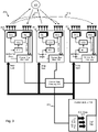
- FIG. 2 An example radar system 200 is illustrated schematically in Figure 2 .
- the system 200 uses two signals provided by a control module 205 via a communications bus 211 to a plurality of transceivers 201 1...n to achieve synchronization in time and frequency of radar signals sent from each transceiver.
- Each transceiver 201 1...n comprises a transmitter TX1 and a receiver RX1 with associated antennae for respectively transmitting and receiving radar signals.
- Separate antennae for transmitting and receiving may be provided, as illustrated in Figure 2 , or common antennae may be used for both transmitting and receiving.
- the frequency of operation of the transmitter TX1 and receiver RX1 in each transceiver is controlled by a voltage-controlled oscillator VCO and phase-locked loop PLL.
- a clock signal is provided to the PLL by a communications bus physical layer (PHY) 202.
- the communications bus PHY 202 in each transceiver 201 1...n is connected to a communications bus gateway 203, which itself is connected to a communications bus PHY 204 of the control module 205.
- the control module 205 which may be a microprocessor, comprises the communications bus PHY 204 and a digital signal processor DSP 206, which processes analog to digital converted (ADC) data 207 from each of the transceivers 201 1...n .
- ADC analog to digital converted
- the control module 205 provides chirp start signals to each of the transceivers to cause the transceivers 201 1...n to start each chirp of a radar signal simultaneously.
- Chirp start signals may be sent to each transceiver via a separate dedicated bus or may be provided as part of a high-speed signal modulated on top of a communication protocol or embedded in the communication protocol.
- the chirp start signal is a triggering signal that allows timing of the transceivers 201 1...n at the start of a modulation sequence.
- the transceivers 201 1...n are each connected to the centralized control module 205 with a synchronized communication connection provided via the gateway 203 and communications bus 202 in each transceiver. Each transceiver 201 1-n recovers the clock signal from the communication bus 202 and uses this as a reference signal, providing an extracted clock signal to the PLL. In this way, all the transceivers 201 1...n will be synchronized in frequency.
- the communications buses 202, 204 and gateway 203 may be provided using Ethernet connections. Alternative communications buses may for example include PCI express or MIPI CSI-2.
- phase differences between the transceivers 201 1...n can be calculated so that any phase difference be compensated.
- Various options may be used to calculate the phase differences.
- One option is to use an over the air (OTA) link or coupling from one of the transceivers to the others.
- OTA link 212 1 , 212 2 is provided from a first one 201 1 of the transceivers to each of the other transceivers 201 2...n .
- a phase difference is calculated between a radar signal transmitted from a first one 201 1 of the plurality of transceivers 201 1-n and a second one 201 2 of the plurality of transceivers 201 1-n from a signal transmitted from a first one 201 1 of the plurality of transceivers 201 1-n and received by the second one 201 2 of the plurality of transceivers 201 1-n ).
- the phase difference between signals from the first and nth transceiver 201 n may be similarly calculated using a signal 212n transmitted from the first transceiver 201 1 and received by the nth transceiver 201 n .
- this option may not be available, for example if the transceivers 201 1-n are relatively located such that direct signals between the transceivers may not be possible.
- Another option in such cases may be to use as a reference the strongest targets common to all the transceivers 201 1...n and to calculate a phase difference between the coherent apertures and the noncoherent aperture. In that case, the phase difference between the coherent aperture and the non coherent aperture can be calculated based on the results of a doppler FFT.
- a convolution between the coherent and the non coherent aperture is calculated for the specific target. The convolution can be calculated in the frequency domain. This is illustrated in Figure 2 , where signals transmitted from and received by the first and second transceivers 201 1,2 are reflected from a common feature 213. A phase difference can then be calculated by convolution of signals from both transceivers 201 1,2 .
- all radar data is transmitted from the transceivers 201 1...n to the control module 205 via the communications bus 211.
- the data is then processed at the control module 205 by the DSP 206.
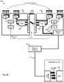
- each transceiver 301 1...n may have an integrated microprocessor 306. Data from each transceiver 301 1...n may be transferred from each transceiver to be centrally processed by the DSP 306 at the control module 205, as shown in Figure 3 , or may be transmitted between the transceivers and transmitted from one transceiver 401 1 to the control module 205, as shown in Figure 4 .
- each transceiver 301 1,2 may be connected to an adjacent transceiver 301 2,1 via a data bus 313, 413.
- FIG 3 shows an example radar system 300 with a master transceiver 301 1 and a slave transceiver 301 2 . Further slave transceivers may also be provided.
- the master transceiver 301 1 controls the start of the modulation and acts as a central unit to process data from both transceivers. Transfer of data between the transceivers 301 1 , 2 can be done via a data bus 313 such as a MIPI-CSI2 communication link, as shown in Figure 3 , or by using another high-speed transfer protocol such as PCI express or by using the communications bus 311, which in this example may be an Ethernet connection.
- the data may be first pre-processed in the master transceiver 301 1 before it is transferred to the control module 205.
- the processor 306 may be distributed between the control module 205 and the plurality of transceivers 301 1 , 2 rather than being located wholly in the control module 205, an advantage of which is to reduce the amount of data needing to be transferred using the, typically slower speed, communications bus 311 by enabling some preprocessing to be carried out on the transceivers 301 1 , 2 .
- FIG. 4 A further example implementation of a radar system 400 is illustrated in Figure 4 , in which the transceivers 401 1 , 2 are co-located, i.e. provided together on a common circuit board or package.
- a master transceiver 401 1 and a slave transceiver 401 2 are shown in Figure 4 .
- Further slave transceivers may be added to the system 400 as required. In this example it may not be necessary to connect all the transceivers 401 1 , 2 separately to a common communication bus 411 and gateway 403 to transfer data to the control module 405 and synchronize the radar system 400 in frequency. Instead, for co-located transceivers 401 1,2 only one of the transceivers (i.e.
- the master 401 1 may have communication with the control module 205, for example via the communications bus 411.
- the master transceiver 401 1 operates to recover the clock signal from the communications bus 411 and provides the clock reference to the slave transceiver 401 2 .
- the phase difference between the transceivers 401 1,2 can be calculated either through coupling between the antennas or by using the strongest target common to the coherent and noncoherent apertures, as detailed above in relation to Figure 2 .
- the data can be transferred from each slave to the master transceiver 401 1 to be processed to be transferred over the communications bus 411 to the common control module 205 or can be transferred to a co-located processing unit.
- Data transfer between the collocated systems can be done through a high-speed data bus like MIPI-CSI2 or PCI Express.
- two or more of the plurality of transceivers may be co-located on a common circuit board or package.
- phase of the reference clock between the transceivers it is important to keep the phase of the reference clock between the transceivers constant.
- a first way of achieving this is to control the electrical length of a connection, such as an ethernet cable, between each of the devices (i.e. between the transceivers and the gateway). This is, however, impractical in any realistic implementation.
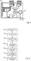
- a second option is to implement a phase shifter in the clock recovery circuit in order to compensate for phase mismatches between reference clocks of the transceivers, as illustrated in Figure 5 .
- a phase shifter 515 on one or more of the transceivers 501 can be used to adjust the phase of the extracted clock signal so that each of the transceivers can subsequently transmit frequency and phase synchronised signals.
- Figure 5 illustrates an example single transceiver 501, which may for example correspond with the master transceiver of Figure 4 , in which the extracted clock signal is provided by the master transceiver to each of the slave transceivers.
- each transceiver may provide its own extracted clock signal and comprise a phase shifter 515 to adjust its extracted clock signal to match that of the master transceiver.
- the described concept can be applied to co-located as well as non-co-located radar systems.
- all the transceivers are located on the same PCB or package.
- One of the main advantages of the proposed concept is that there is no necessity to distribute a high frequency signal from a master device to multiple slave devices.
- the transceivers can be positioned in the PCB in a more flexible way, thereby reducing the distance between the transceiver and the antennae.
- the antennae are already integrated into the transceiver or if there is an interface to 3D antennas integrated into the transceiver, there is no necessity to use expensive high frequency PCB substrates.
- FIG. 6 illustrates an example method of operating a radar system of the types as described above.
- the method comprises generating a first clock signal (step 601), which is done by the control module 205.
- the first clock signal which may for example be within a first frequency range of 10-100MHz, is transmitted via the communications bus to one or more of the plurality of transceivers (step 602).
- the clock signal may for example be sent to each of the transceivers individually or may be sent to only one of the transceivers.
- One or more of the plurality of transceivers then generates a second clock signal extracted from the first clock signal (step 603).
- the second clock signal may for example be within a radar range of frequencies, i.e. within the range of 10-100 GHz.
- the extracted second clock signal is sent from one of the transceivers to one or more of the other transceivers, for example in cases where the transceivers are co-located, while in other cases each of the transceivers may generate its own extracted second clock signal.
- Each of the plurality of transceivers then transmits and receives frequency synchronised radar signals based on the second clock signal (step 604).
- the processing module 206 determines whether provided within the control module 205 or distributed between the control module 205 and each of the transceivers, calculates a phase difference between the frequency synchronized radar signals (step 605), i.e. between a master transceiver and each of the other transceivers.
- the processing module then compensates for the measured phase difference (step 606) and processes received radar signals from the plurality of transceivers (step 607).
- Steps 606 and 607 may involve processing the received radar signals to account for the phase differences or may involve first adjusting a phase of the second clock signal in each of the plurality of transceivers so that the radar signals are frequency and phase synchronized.
Landscapes
- Engineering & Computer Science (AREA)
- Radar, Positioning & Navigation (AREA)
- Remote Sensing (AREA)
- Computer Networks & Wireless Communication (AREA)
- Physics & Mathematics (AREA)
- General Physics & Mathematics (AREA)
- Electromagnetism (AREA)
- Signal Processing (AREA)
- Radar Systems Or Details Thereof (AREA)
Abstract
Description
- The disclosure relates to a radar system in which multiple radar transceivers are synchronised with a common clock signal.
- In current automotive radar systems, the radar aperture may be increased by cascading multiple transceivers to increase the angular resolution of the complete system. To process data from multiple transceivers coherently, synchronization of both frequency and phase is necessary. This may be achieved by distributing a high frequency local oscillator (LO) signal from a master transceiver to one or more slave transceivers. However, in radar systems the LO signal is typically in the region of 10-100 GHz (for example within the range 25 to 40 GHz). Transmitting such signals over distances greater than a few cm without the use of waveguides is problematic due to substantial transmission losses.
- According to a first aspect there is provided a radar system comprising:
- a control module;
- a processing module;
- a plurality of radar transceivers; and
- a communications bus connecting the control module to one or more of the plurality of radar transceivers,
- The radar system is a distributed radar system, in which data from the plurality of transceivers is combined to provide a more accurate picture of the surrounding environment, rather than being analysed separately to provide multiple separate pictures from different views. The plurality of transceivers may be provided on separate circuit boards so that they can be located at separate positions, for example along the front of a vehicle. In alternative arrangements the radar system may be a co-located radar system, in which the plurality of transceivers are located on a common circuit board.
- In some examples the control module comprises the processing module, while in others the processing module may be distributed among the control module and the transceivers.
- The communications bus may connect the control module to each one of the plurality of radar transceivers, each of the plurality of radar transceivers being configured to receive the first clock signal from the control module via the communications bus.
- In some examples, the processing module may be configured to calculate the phase difference between a radar signal transmitted from a first one of the plurality of transceivers and a second one of the plurality of transceivers from a signal transmitted from a first one of the plurality of transceivers and received by the second one of the plurality of transceivers.
- In alternative examples, the processing module may be configured to calculate the phase difference between a radar signal transmitted from a first one of the plurality of transceivers and a second one of the plurality of transceivers from signals transmitted and received by each of the first and second ones of the plurality of transmitters and reflected from a common feature.
- Each transceiver may be connected to an adjacent transceiver via a data bus, thereby allowing high speed communication between adjacent transceivers, for example to allow chirp start signals to be transmitted and for radar signals and data to be transmitted between transceivers.
- Two or more of the plurality of transceivers may be co-located on a common circuit board or package.
- Each of the plurality of transceivers may comprise a phase adjuster configured to adjust a phase of the second clock signal, the processing module being configured to operate the phase adjuster to compensate for the calculated phase difference.
- According to a second aspect there is provided a method of operating a radar system comprising a control module, a processing module, a plurality of radar transceivers and a communications bus connecting the control module to one or more of the plurality of radar transceivers, the method comprising:
- generating by the control module a first clock signal;
- transmitting by the control module the first clock signal via the communications bus to one or more of the plurality of transceivers;
- generating by one or more of the plurality of transceivers a second clock signal extracted from the first clock signal;
- transmitting and receiving frequency synchronized radar signals by each of the plurality of transceivers based on the second clock signal;
- calculating by the processing module a phase difference between the frequency synchronized radar signals;
- compensating by the processing module for the measured phase difference; and
- processing by the processing module received radar signals from the plurality of transceivers.
- The first clock signal may be transmitted to each of the plurality of transceivers via the communications bus.
- The method may comprise adjusting a phase of the second clock signal in each of the transceivers with a phase adjuster to compensate for the measured phase difference.
- In some examples the processing module may calculate the phase difference between a radar signal transmitted from a first one of the plurality of transceivers and a second one of the plurality of transceivers from a signal transmitted from a first one of the plurality of transceivers and received by the second one of the plurality of transceivers.
- In other examples the processing module may calculate the phase difference between a radar signal transmitted from a first one of the plurality of transceivers and a second one of the plurality of transceivers from signals transmitted and received by each of the first and second ones of the plurality of transmitters and reflected from a common feature.
- These and other aspects of the invention will be apparent from, and elucidated with reference to, the embodiments described hereinafter.
- Embodiments will be described, by way of example only, with reference to the drawings, in which:
-
Figure 1 is a schematic plan view of a vehicle with a distributed radar system having multiple transceivers; -
Figure 2 is a schematic diagram of a distributed radar system with multiple transceivers; -
Figure 3 is a schematic diagram of an example radar system with signal processing performed on each transceiver; -
Figure 4 is a schematic diagram of an alternative example radar system with signal processing performed on each transceiver; -
Figure 5 is a schematic diagram of an example radar transceiver with a phase shifted output clock signal; and -
Figure 6 is a schematic flow diagram illustrating a method of operating a radar system having multiple transceivers. - It should be noted that the Figures are diagrammatic and not drawn to scale. Relative dimensions and proportions of parts of these Figures have been shown exaggerated or reduced in size, for the sake of clarity and convenience in the drawings. The same reference signs are generally used to refer to corresponding or similar feature in modified and different embodiments.
-
Figure 1 illustrates avehicle 100 with a distributed cooperative radar system. The radar system comprises a plurality oftransceivers 101a-c positioned along a front portion of the vehicle. Other transceivers may be positioned around the sides or rear of the vehicle. Each transceiver has a respective field ofview 102a-c, which overlap in overlappingregions transceivers 101a-c are distributed in space across the front of thevehicle 100, information from a wider field of view can be gathered. If the transceivers are connected to operate together cooperatively, the angular resolution of the complete system can also be increased compared with non-cooperative individual transceivers. This, however, requires thetransceivers 101a-c to be synchronized both in frequency and in phase to allow information from each transceiver to be combined. - Proposed herein is a radar system that can be used to synchronize and transport data in a coherent distributed system. The transceivers in the system can be co-located or distributed in space. An
example radar system 200 is illustrated schematically inFigure 2 . Thesystem 200 uses two signals provided by acontrol module 205 via acommunications bus 211 to a plurality oftransceivers 2011...n to achieve synchronization in time and frequency of radar signals sent from each transceiver. Eachtransceiver 2011...n comprises a transmitter TX1 and a receiver RX1 with associated antennae for respectively transmitting and receiving radar signals. Separate antennae for transmitting and receiving may be provided, as illustrated inFigure 2 , or common antennae may be used for both transmitting and receiving. The frequency of operation of the transmitter TX1 and receiver RX1 in each transceiver is controlled by a voltage-controlled oscillator VCO and phase-locked loop PLL. A clock signal is provided to the PLL by a communications bus physical layer (PHY) 202. The communications bus PHY 202 in eachtransceiver 2011...n is connected to a communications bus gateway 203, which itself is connected to acommunications bus PHY 204 of thecontrol module 205. Thecontrol module 205, which may be a microprocessor, comprises thecommunications bus PHY 204 and a digital signal processor DSP 206, which processes analog to digital converted (ADC)data 207 from each of thetransceivers 2011...n. - The
control module 205 provides chirp start signals to each of the transceivers to cause thetransceivers 2011...n to start each chirp of a radar signal simultaneously. Chirp start signals may be sent to each transceiver via a separate dedicated bus or may be provided as part of a high-speed signal modulated on top of a communication protocol or embedded in the communication protocol. The chirp start signal is a triggering signal that allows timing of thetransceivers 2011...n at the start of a modulation sequence. - The
transceivers 2011...n are each connected to thecentralized control module 205 with a synchronized communication connection provided via the gateway 203 and communications bus 202 in each transceiver. Eachtransceiver 2011-n recovers the clock signal from the communication bus 202 and uses this as a reference signal, providing an extracted clock signal to the PLL. In this way, all thetransceivers 2011...n will be synchronized in frequency. Thecommunications buses 202, 204 and gateway 203 may be provided using Ethernet connections. Alternative communications buses may for example include PCI express or MIPI CSI-2. - Although the frequency of operation of each of the
transceivers 2011...n is synchronized, the phase will not be synchronized but this can be compensated for. Any phase differences between thetransceivers 2011...n can be calculated so that any phase difference be compensated. Various options may be used to calculate the phase differences. One option is to use an over the air (OTA) link or coupling from one of the transceivers to the others. In thesystem 200 ofFigure 2 , anOTA link other transceivers 2012...n. According to this option, a phase difference is calculated between a radar signal transmitted from a first one 2011 of the plurality oftransceivers 2011-n and a second one 2012 of the plurality oftransceivers 2011-n from a signal transmitted from a first one 2011 of the plurality oftransceivers 2011-n and received by the second one 2012 of the plurality of transceivers 2011-n). The phase difference between signals from the first andnth transceiver 201n may be similarly calculated using a signal 212n transmitted from thefirst transceiver 2011 and received by thenth transceiver 201n. In some cases this option may not be available, for example if thetransceivers 2011-n are relatively located such that direct signals between the transceivers may not be possible. Another option in such cases may be to use as a reference the strongest targets common to all thetransceivers 2011...n and to calculate a phase difference between the coherent apertures and the noncoherent aperture. In that case, the phase difference between the coherent aperture and the non coherent aperture can be calculated based on the results of a doppler FFT. To calculate the calibrated phase, a convolution between the coherent and the non coherent aperture is calculated for the specific target. The convolution can be calculated in the frequency domain. This is illustrated inFigure 2 , where signals transmitted from and received by the first andsecond transceivers 2011,2 are reflected from acommon feature 213. A phase difference can then be calculated by convolution of signals from bothtransceivers 2011,2. - In the example in
Figure 2 , all radar data is transmitted from thetransceivers 2011...n to thecontrol module 205 via thecommunications bus 211. The data is then processed at thecontrol module 205 by the DSP 206. - In an alternative implementation, as shown in
Figure 3 , each transceiver 3011...n may have an integratedmicroprocessor 306. Data from each transceiver 3011...n may be transferred from each transceiver to be centrally processed by theDSP 306 at thecontrol module 205, as shown inFigure 3 , or may be transmitted between the transceivers and transmitted from onetransceiver 4011 to thecontrol module 205, as shown inFigure 4 . In each implementation, each transceiver 3011,2 may be connected to an adjacent transceiver 3012,1 via adata bus -
Figure 3 shows anexample radar system 300 with a master transceiver 3011 and a slave transceiver 3012. Further slave transceivers may also be provided. The master transceiver 3011 controls the start of the modulation and acts as a central unit to process data from both transceivers. Transfer of data between the transceivers 3011,2 can be done via adata bus 313 such as a MIPI-CSI2 communication link, as shown inFigure 3 , or by using another high-speed transfer protocol such as PCI express or by using thecommunications bus 311, which in this example may be an Ethernet connection. To reduce the amount of data transferred to theprocessor 306 on thecontrol module 205, the data may be first pre-processed in the master transceiver 3011 before it is transferred to thecontrol module 205. In a general aspect therefore, theprocessor 306 may be distributed between thecontrol module 205 and the plurality of transceivers 3011,2 rather than being located wholly in thecontrol module 205, an advantage of which is to reduce the amount of data needing to be transferred using the, typically slower speed,communications bus 311 by enabling some preprocessing to be carried out on the transceivers 3011,2. - A further example implementation of a
radar system 400 is illustrated inFigure 4 , in which thetransceivers 4011,2 are co-located, i.e. provided together on a common circuit board or package. Amaster transceiver 4011 and aslave transceiver 4012 are shown inFigure 4 . Further slave transceivers may be added to thesystem 400 as required. In this example it may not be necessary to connect all thetransceivers 4011,2 separately to acommon communication bus 411 andgateway 403 to transfer data to the control module 405 and synchronize theradar system 400 in frequency. Instead, forco-located transceivers 4011,2 only one of the transceivers (i.e. the master 4011) may have communication with thecontrol module 205, for example via thecommunications bus 411. Themaster transceiver 4011 operates to recover the clock signal from thecommunications bus 411 and provides the clock reference to theslave transceiver 4012. The phase difference between thetransceivers 4011,2 can be calculated either through coupling between the antennas or by using the strongest target common to the coherent and noncoherent apertures, as detailed above in relation toFigure 2 . The data can be transferred from each slave to themaster transceiver 4011 to be processed to be transferred over thecommunications bus 411 to thecommon control module 205 or can be transferred to a co-located processing unit. Data transfer between the collocated systems (transceiver and or microprocessors) can be done through a high-speed data bus like MIPI-CSI2 or PCI Express. In a general aspect therefore, two or more of the plurality of transceivers may be co-located on a common circuit board or package. - For any of the above-mentioned example implementations, it is important to keep the phase of the reference clock between the transceivers constant. A first way of achieving this is to control the electrical length of a connection, such as an ethernet cable, between each of the devices (i.e. between the transceivers and the gateway). This is, however, impractical in any realistic implementation. A second option is to implement a phase shifter in the clock recovery circuit in order to compensate for phase mismatches between reference clocks of the transceivers, as illustrated in
Figure 5 . Once a phase difference has been calculated between each of the plurality of transceivers, aphase shifter 515 on one or more of thetransceivers 501 can be used to adjust the phase of the extracted clock signal so that each of the transceivers can subsequently transmit frequency and phase synchronised signals.Figure 5 illustrates an examplesingle transceiver 501, which may for example correspond with the master transceiver ofFigure 4 , in which the extracted clock signal is provided by the master transceiver to each of the slave transceivers. In other implementations each transceiver may provide its own extracted clock signal and comprise aphase shifter 515 to adjust its extracted clock signal to match that of the master transceiver. - The described concept can be applied to co-located as well as non-co-located radar systems. In a co-located radar system, all the transceivers are located on the same PCB or package. One of the main advantages of the proposed concept is that there is no necessity to distribute a high frequency signal from a master device to multiple slave devices. There are also two further advantages. Firstly, the transceivers can be positioned in the PCB in a more flexible way, thereby reducing the distance between the transceiver and the antennae. Secondly, if the antennae are already integrated into the transceiver or if there is an interface to 3D antennas integrated into the transceiver, there is no necessity to use expensive high frequency PCB substrates.
-
Figure 6 illustrates an example method of operating a radar system of the types as described above. The method comprises generating a first clock signal (step 601), which is done by thecontrol module 205. The first clock signal, which may for example be within a first frequency range of 10-100MHz, is transmitted via the communications bus to one or more of the plurality of transceivers (step 602). The clock signal may for example be sent to each of the transceivers individually or may be sent to only one of the transceivers. One or more of the plurality of transceivers then generates a second clock signal extracted from the first clock signal (step 603). The second clock signal may for example be within a radar range of frequencies, i.e. within the range of 10-100 GHz. In some cases the extracted second clock signal is sent from one of the transceivers to one or more of the other transceivers, for example in cases where the transceivers are co-located, while in other cases each of the transceivers may generate its own extracted second clock signal. Each of the plurality of transceivers then transmits and receives frequency synchronised radar signals based on the second clock signal (step 604). Based on these radar signals, the processing module 206, whether provided within thecontrol module 205 or distributed between thecontrol module 205 and each of the transceivers, calculates a phase difference between the frequency synchronized radar signals (step 605), i.e. between a master transceiver and each of the other transceivers. The processing module then compensates for the measured phase difference (step 606) and processes received radar signals from the plurality of transceivers (step 607).Steps 606 and 607 may involve processing the received radar signals to account for the phase differences or may involve first adjusting a phase of the second clock signal in each of the plurality of transceivers so that the radar signals are frequency and phase synchronized. - From reading the present disclosure, other variations and modifications will be apparent to the skilled person. Such variations and modifications may involve equivalent and other features which are already known in the art of radar systems, and which may be used instead of, or in addition to, features already described herein.
- Although the appended claims are directed to particular combinations of features, it should be understood that the scope of the disclosure of the present invention also includes any novel feature or any novel combination of features disclosed herein either explicitly or implicitly or any generalisation thereof, whether or not it relates to the same invention as presently claimed in any claim and whether or not it mitigates any or all of the same technical problems as does the present invention.
- Features which are described in the context of separate embodiments may also be provided in combination in a single embodiment. Conversely, various features which are, for brevity, described in the context of a single embodiment, may also be provided separately or in any suitable sub-combination. The applicant hereby gives notice that new claims may be formulated to such features and/or combinations of such features during the prosecution of the present application or of any further application derived therefrom.
- For the sake of completeness it is also stated that the term "comprising" does not exclude other elements or steps, the term "a" or "an" does not exclude a plurality, a single processor or other unit may fulfil the functions of several means recited in the claims and reference signs in the claims shall not be construed as limiting the scope of the claims.
wherein each of the plurality of transceivers is configured to generate a second clock signal extracted from the first clock signal and to transmit and receive frequency synchronized radar signals based on the second clock signal, and
wherein the processing module is configured to: calculate a phase difference between the frequency synchronized radar signals; compensate for the measured phase difference; and process received radar signals from the plurality of transceivers.
Claims (14)
- A radar system (200) comprising:a control module (205);a processing module (206);a plurality of radar transceivers (2011-n); anda communications bus (211) connecting the control module (205) to one or more of the plurality of radar transceivers (2011-n),wherein the control module (205) is configured to generate a first clock signal and transmit the first clock signal via the communications bus (211) to one or more of the plurality of transceivers (2011-n) and to receive radar data from the plurality of transceivers (2011-n) via the communications bus (211),wherein each of the plurality of transceivers (2011-n) is configured to generate a second clock signal extracted from the first clock signal and to transmit and receive frequency synchronized radar signals based on the second clock signal,and wherein the processing module (206) is configured to: calculate a phase difference between the frequency synchronized radar signals; compensate for the measured phase difference; and process received radar signals from the plurality of transceivers (2011-n).
- The radar system (200) of claim 1, wherein the control module (205) comprises the processing module (206).
- The radar system (200) of claim 1 or claim 2, wherein the communications bus (211) connects the control module (205) to each one of the plurality of radar transceivers (2011-n), each of the plurality of radar transceivers (2011-n) being configured to receive the first clock signal from the control module (205) via the communications bus (211).
- The radar system (200) of any preceding claim, wherein the processing module (206) is configured to calculate the phase difference between a radar signal transmitted from a first one (2011) of the plurality of transceivers (2011-n) and a second one (2012) of the plurality of transceivers (2011-n) from a signal transmitted from a first one (2011) of the plurality of transceivers (2011-n) and received by the second one (2012) of the plurality of transceivers (2011-n).
- The radar system (200) of any preceding claim, wherein the processing module (206) is configured to calculate the phase difference between a radar signal transmitted from a first one (2011) of the plurality of transceivers (2011-n) and a second one (2012) of the plurality of transceivers (2011-n) from signals transmitted and received by each of the first and second ones (2011,2) of the plurality of transmitters (2011-n) and reflected from a common feature (213).
- The radar system (300) of any preceding claim, wherein the processing module (306) is distributed between the control module (205) and the plurality of transceivers (3011,2).
- The radar system (300, 400) of any preceding claim, wherein each transceiver (3011,2) is connected to an adjacent transceiver (3012,1) via a data bus (313).
- The radar system (400) of any preceding claim, wherein two or more of the plurality of transceivers are co-located on a common circuit board or package.
- The radar system (200) of any preceding claim, wherein each of the plurality of transceivers (501) comprises a phase adjuster (515) configured to adjust a phase of the second clock signal, the processing module (206) being configured to operate the phase adjuster to compensate for the calculated phase difference.
- A method of operating a radar system (200) comprising a control module (205), a processing module (206), a plurality of radar transceivers (2011-n) and a communications bus (211) connecting the control module (205) to one or more of the plurality of radar transceivers (2011-n), the method comprising:generating by the control module (205) a first clock signal;transmitting by the control module (205) the first clock signal via the communications bus (211) to one or more of the plurality of transceivers (2011-n); generating by one or more of the plurality of transceivers (2011-n) a second clock signal extracted from the first clock signal;transmitting and receiving frequency synchronized radar signals by each of the plurality of transceivers (2011-n) based on the second clock signal;calculating by the processing module (206) a phase difference between the frequency synchronized radar signals;compensating by the processing module (206) for the measured phase difference; andprocessing by the processing module (206) received radar signals from the plurality of transceivers (2011-n).
- The method of claim 10, wherein the first clock signal is transmitted to each of the plurality of transceivers (2011-n) via the communications bus (211).
- The method of claim 10 or claim 11 comprising adjusting a phase of the second clock signal in each of the transceivers with a phase adjuster to compensate for the measured phase difference.
- The method of any one of claims 10 to 12, wherein the processing module (206) calculates the phase difference between a radar signal transmitted from a first one (2011) of the plurality of transceivers (2011-n) and a second one (2012) of the plurality of transceivers (2011-n) from a signal transmitted from a first one (2011) of the plurality of transceivers (2011-n) and received by the second one (2012) of the plurality of transceivers (2011-n).
- The method of any one of claims 10 to 12, wherein the processing module (206) calculates the phase difference between a radar signal transmitted from a first one (2011) of the plurality of transceivers (2011-n) and a second one (2012) of the plurality of transceivers (2011-n) from signals transmitted and received by each of the first and second ones (2011,2) of the plurality of transmitters (2011-n) and reflected from a common feature (213).
Priority Applications (3)
| Application Number | Priority Date | Filing Date | Title |
|---|---|---|---|
| EP20216934.8A EP4019998A1 (en) | 2020-12-23 | 2020-12-23 | Distributed radar system |
| US17/643,213 US12313729B2 (en) | 2020-12-23 | 2021-12-08 | Distributed radar system |
| CN202111586447.8A CN114660543A (en) | 2020-12-23 | 2021-12-23 | Distributed radar system |
Applications Claiming Priority (1)
| Application Number | Priority Date | Filing Date | Title |
|---|---|---|---|
| EP20216934.8A EP4019998A1 (en) | 2020-12-23 | 2020-12-23 | Distributed radar system |
Publications (1)
| Publication Number | Publication Date |
|---|---|
| EP4019998A1 true EP4019998A1 (en) | 2022-06-29 |
Family
ID=73857066
Family Applications (1)
| Application Number | Title | Priority Date | Filing Date |
|---|---|---|---|
| EP20216934.8A Withdrawn EP4019998A1 (en) | 2020-12-23 | 2020-12-23 | Distributed radar system |
Country Status (3)
| Country | Link |
|---|---|
| US (1) | US12313729B2 (en) |
| EP (1) | EP4019998A1 (en) |
| CN (1) | CN114660543A (en) |
Cited By (1)
| Publication number | Priority date | Publication date | Assignee | Title |
|---|---|---|---|---|
| WO2023198481A1 (en) * | 2022-04-11 | 2023-10-19 | Hella | Method for detecting an object, radar system and vehicle |
Families Citing this family (4)
| Publication number | Priority date | Publication date | Assignee | Title |
|---|---|---|---|---|
| US20230305140A1 (en) * | 2022-02-28 | 2023-09-28 | Ramesh Annavajjala | Method and Apparatus for Multi-Processor Radar Signal Processing |
| CN115598643A (en) * | 2022-10-13 | 2023-01-13 | 苏州豪米波技术有限公司(Cn) | Centralized computing millimeter wave radar system adopting high-speed digital bus and detection method |
| DE102023203975A1 (en) * | 2023-04-28 | 2024-10-31 | Robert Bosch Gesellschaft mit beschränkter Haftung | Radar system and method for operating a radar system |
| WO2025255842A1 (en) * | 2024-06-14 | 2025-12-18 | 清华大学 | Distributed radar transceiver system |
Citations (2)
| Publication number | Priority date | Publication date | Assignee | Title |
|---|---|---|---|---|
| DE102019211431A1 (en) * | 2019-07-31 | 2020-07-09 | Audi Ag | Method for operating radar sensors in a motor vehicle and motor vehicle |
| US20200341112A1 (en) * | 2019-04-23 | 2020-10-29 | Infineon Technologies Ag | Calibration of a radar system |
Family Cites Families (14)
| Publication number | Priority date | Publication date | Assignee | Title |
|---|---|---|---|---|
| US8922421B2 (en) * | 2009-12-10 | 2014-12-30 | Lockheed Martin Corporation | Method and system for use of GPS disciplined oscillators for coherent timing reference in distributed radar systems |
| US10627480B2 (en) | 2014-07-17 | 2020-04-21 | Texas Instruments Incorporated | Distributed radar signal processing in a radar system |
| US9910133B2 (en) | 2015-02-25 | 2018-03-06 | Infineon Technologies Ag | Systems and methods for cascading radar chips having a low leakage buffer |
| CN106526582B (en) * | 2015-08-28 | 2022-10-04 | 安波福技术有限公司 | Bistatic Radar System |
| EP3168637A1 (en) * | 2015-11-12 | 2017-05-17 | Autoliv Development AB | A modular vehicle radar |
| EP3327461B1 (en) * | 2016-11-23 | 2020-11-04 | NXP USA, Inc. | Digital synthesizer, radar device and method therefor |
| US20180292510A1 (en) | 2017-04-07 | 2018-10-11 | Texas Instruments Incorporated | Calibration of a cascaded radar system |
| EP3505952B1 (en) * | 2018-01-02 | 2022-04-20 | NXP USA, Inc. | Radar apparatus and method |
| EP3591431B1 (en) * | 2018-07-02 | 2021-05-05 | NXP USA, Inc. | Communication unit and method for clock distribution and synchronization |
| US11092683B2 (en) | 2019-03-18 | 2021-08-17 | Nxp Usa, Inc. | Distributed aperture automotive radar system with alternating master radar devices |
| US11269049B2 (en) | 2019-03-18 | 2022-03-08 | Nxp Usa, Inc. | Distributed aperture automotive radar system |
| KR102834783B1 (en) * | 2019-04-30 | 2025-07-17 | 젠다르 인코퍼레이티드 | Radar data combining system and method |
| CN110703246B (en) * | 2019-10-24 | 2020-11-27 | 中国科学院电子学研究所 | A signal synchronization device and system |
| KR102764903B1 (en) * | 2020-01-09 | 2025-02-12 | 매그나칩믹스드시그널 유한회사 | Spread spectrum clock generation appratus for generating spread spectrum clock signal and a method for operating the same |
-
2020
- 2020-12-23 EP EP20216934.8A patent/EP4019998A1/en not_active Withdrawn
-
2021
- 2021-12-08 US US17/643,213 patent/US12313729B2/en active Active
- 2021-12-23 CN CN202111586447.8A patent/CN114660543A/en active Pending
Patent Citations (2)
| Publication number | Priority date | Publication date | Assignee | Title |
|---|---|---|---|---|
| US20200341112A1 (en) * | 2019-04-23 | 2020-10-29 | Infineon Technologies Ag | Calibration of a radar system |
| DE102019211431A1 (en) * | 2019-07-31 | 2020-07-09 | Audi Ag | Method for operating radar sensors in a motor vehicle and motor vehicle |
Cited By (1)
| Publication number | Priority date | Publication date | Assignee | Title |
|---|---|---|---|---|
| WO2023198481A1 (en) * | 2022-04-11 | 2023-10-19 | Hella | Method for detecting an object, radar system and vehicle |
Also Published As
| Publication number | Publication date |
|---|---|
| US20220196826A1 (en) | 2022-06-23 |
| US12313729B2 (en) | 2025-05-27 |
| CN114660543A (en) | 2022-06-24 |
Similar Documents
| Publication | Publication Date | Title |
|---|---|---|
| US12313729B2 (en) | Distributed radar system | |
| US12429555B2 (en) | Multi-chip synchronization for digital radars | |
| CN110736966B (en) | Communication unit, integrated circuit and method for synchronizing clock and data | |
| CN110740029A (en) | Communication unit, integrated circuit and method for clock and data synchronization | |
| EP3591431B1 (en) | Communication unit and method for clock distribution and synchronization | |
| CN108603928A (en) | For reducing the method and system interfered caused by the phase noise in radar system | |
| JP7399196B2 (en) | Base station multi-channel phase synchronization device, method and base station | |
| MXPA02000741A (en) | Method and apparatus for sequentially synchronizing a radio network. | |
| EP3859376B1 (en) | Synchronization of multiple mmwave devices | |
| US11668793B2 (en) | Radar system | |
| US11353570B2 (en) | Radar system and method for operating a radar system | |
| KR100211581B1 (en) | Hodata transmission method of paging system using reference clock signal delay circuit from GPS receiver | |
| WO2021125381A1 (en) | Fmcw radar transmission and reception apparatus using plurality of plls | |
| US20240385283A1 (en) | Radar signal generator arrangement, radar arrangement and radar system | |
| US8565293B2 (en) | Method for synchronizing a plurality of measuring channel assemblies and/or measuring devices, and appropriate measuring device | |
| JPH07333328A (en) | Radar | |
| CN109818699B (en) | System for broadcasting a time reference in an aircraft | |
| EP3982548B1 (en) | Frequency generation of a multi-antenna transceiver system | |
| KR100661518B1 (en) | System Timing Signal Providing Device in Mobile Internet Base Station System | |
| JP2004274291A (en) | Synchronous network device |
Legal Events
| Date | Code | Title | Description |
|---|---|---|---|
| PUAI | Public reference made under article 153(3) epc to a published international application that has entered the european phase |
Free format text: ORIGINAL CODE: 0009012 |
|
| STAA | Information on the status of an ep patent application or granted ep patent |
Free format text: STATUS: THE APPLICATION HAS BEEN PUBLISHED |
|
| AK | Designated contracting states |
Kind code of ref document: A1 Designated state(s): AL AT BE BG CH CY CZ DE DK EE ES FI FR GB GR HR HU IE IS IT LI LT LU LV MC MK MT NL NO PL PT RO RS SE SI SK SM TR |
|
| STAA | Information on the status of an ep patent application or granted ep patent |
Free format text: STATUS: REQUEST FOR EXAMINATION WAS MADE |
|
| 17P | Request for examination filed |
Effective date: 20230102 |
|
| RBV | Designated contracting states (corrected) |
Designated state(s): AL AT BE BG CH CY CZ DE DK EE ES FI FR GB GR HR HU IE IS IT LI LT LU LV MC MK MT NL NO PL PT RO RS SE SI SK SM TR |
|
| STAA | Information on the status of an ep patent application or granted ep patent |
Free format text: STATUS: EXAMINATION IS IN PROGRESS |
|
| 17Q | First examination report despatched |
Effective date: 20241211 |
|
| STAA | Information on the status of an ep patent application or granted ep patent |
Free format text: STATUS: THE APPLICATION IS DEEMED TO BE WITHDRAWN |
|
| 18D | Application deemed to be withdrawn |
Effective date: 20250412 |