EP4019865A1 - Cooling appliance having multiple cooling compartments in fluid communication with each other - Google Patents
Cooling appliance having multiple cooling compartments in fluid communication with each other Download PDFInfo
- Publication number
- EP4019865A1 EP4019865A1 EP20855557.3A EP20855557A EP4019865A1 EP 4019865 A1 EP4019865 A1 EP 4019865A1 EP 20855557 A EP20855557 A EP 20855557A EP 4019865 A1 EP4019865 A1 EP 4019865A1
- Authority
- EP
- European Patent Office
- Prior art keywords
- chamber
- chilled
- fan
- chilled chamber
- evaporator
- Prior art date
- Legal status (The legal status is an assumption and is not a legal conclusion. Google has not performed a legal analysis and makes no representation as to the accuracy of the status listed.)
- Withdrawn
Links
Images


Classifications
-
- F—MECHANICAL ENGINEERING; LIGHTING; HEATING; WEAPONS; BLASTING
- F25—REFRIGERATION OR COOLING; COMBINED HEATING AND REFRIGERATION SYSTEMS; HEAT PUMP SYSTEMS; MANUFACTURE OR STORAGE OF ICE; LIQUEFACTION SOLIDIFICATION OF GASES
- F25D—REFRIGERATORS; COLD ROOMS; ICE-BOXES; COOLING OR FREEZING APPARATUS NOT OTHERWISE PROVIDED FOR
- F25D17/00—Arrangements for circulating cooling fluids; Arrangements for circulating gas, e.g. air, within refrigerated spaces
- F25D17/04—Arrangements for circulating cooling fluids; Arrangements for circulating gas, e.g. air, within refrigerated spaces for circulating air, e.g. by convection
- F25D17/06—Arrangements for circulating cooling fluids; Arrangements for circulating gas, e.g. air, within refrigerated spaces for circulating air, e.g. by convection by forced circulation
- F25D17/062—Arrangements for circulating cooling fluids; Arrangements for circulating gas, e.g. air, within refrigerated spaces for circulating air, e.g. by convection by forced circulation in household refrigerators
- F25D17/065—Arrangements for circulating cooling fluids; Arrangements for circulating gas, e.g. air, within refrigerated spaces for circulating air, e.g. by convection by forced circulation in household refrigerators with compartments at different temperatures
-
- F—MECHANICAL ENGINEERING; LIGHTING; HEATING; WEAPONS; BLASTING
- F25—REFRIGERATION OR COOLING; COMBINED HEATING AND REFRIGERATION SYSTEMS; HEAT PUMP SYSTEMS; MANUFACTURE OR STORAGE OF ICE; LIQUEFACTION SOLIDIFICATION OF GASES
- F25D—REFRIGERATORS; COLD ROOMS; ICE-BOXES; COOLING OR FREEZING APPARATUS NOT OTHERWISE PROVIDED FOR
- F25D11/00—Self-contained movable devices, e.g. domestic refrigerators
- F25D11/02—Self-contained movable devices, e.g. domestic refrigerators with cooling compartments at different temperatures
-
- F—MECHANICAL ENGINEERING; LIGHTING; HEATING; WEAPONS; BLASTING
- F25—REFRIGERATION OR COOLING; COMBINED HEATING AND REFRIGERATION SYSTEMS; HEAT PUMP SYSTEMS; MANUFACTURE OR STORAGE OF ICE; LIQUEFACTION SOLIDIFICATION OF GASES
- F25D—REFRIGERATORS; COLD ROOMS; ICE-BOXES; COOLING OR FREEZING APPARATUS NOT OTHERWISE PROVIDED FOR
- F25D17/00—Arrangements for circulating cooling fluids; Arrangements for circulating gas, e.g. air, within refrigerated spaces
- F25D17/04—Arrangements for circulating cooling fluids; Arrangements for circulating gas, e.g. air, within refrigerated spaces for circulating air, e.g. by convection
- F25D17/06—Arrangements for circulating cooling fluids; Arrangements for circulating gas, e.g. air, within refrigerated spaces for circulating air, e.g. by convection by forced circulation
- F25D17/067—Evaporator fan units
-
- F—MECHANICAL ENGINEERING; LIGHTING; HEATING; WEAPONS; BLASTING
- F25—REFRIGERATION OR COOLING; COMBINED HEATING AND REFRIGERATION SYSTEMS; HEAT PUMP SYSTEMS; MANUFACTURE OR STORAGE OF ICE; LIQUEFACTION SOLIDIFICATION OF GASES
- F25D—REFRIGERATORS; COLD ROOMS; ICE-BOXES; COOLING OR FREEZING APPARATUS NOT OTHERWISE PROVIDED FOR
- F25D17/00—Arrangements for circulating cooling fluids; Arrangements for circulating gas, e.g. air, within refrigerated spaces
- F25D17/04—Arrangements for circulating cooling fluids; Arrangements for circulating gas, e.g. air, within refrigerated spaces for circulating air, e.g. by convection
- F25D17/06—Arrangements for circulating cooling fluids; Arrangements for circulating gas, e.g. air, within refrigerated spaces for circulating air, e.g. by convection by forced circulation
- F25D17/08—Arrangements for circulating cooling fluids; Arrangements for circulating gas, e.g. air, within refrigerated spaces for circulating air, e.g. by convection by forced circulation using ducts
-
- F—MECHANICAL ENGINEERING; LIGHTING; HEATING; WEAPONS; BLASTING
- F25—REFRIGERATION OR COOLING; COMBINED HEATING AND REFRIGERATION SYSTEMS; HEAT PUMP SYSTEMS; MANUFACTURE OR STORAGE OF ICE; LIQUEFACTION SOLIDIFICATION OF GASES
- F25B—REFRIGERATION MACHINES, PLANTS OR SYSTEMS; COMBINED HEATING AND REFRIGERATION SYSTEMS; HEAT PUMP SYSTEMS
- F25B2600/00—Control issues
- F25B2600/11—Fan speed control
- F25B2600/112—Fan speed control of evaporator fans
-
- F—MECHANICAL ENGINEERING; LIGHTING; HEATING; WEAPONS; BLASTING
- F25—REFRIGERATION OR COOLING; COMBINED HEATING AND REFRIGERATION SYSTEMS; HEAT PUMP SYSTEMS; MANUFACTURE OR STORAGE OF ICE; LIQUEFACTION SOLIDIFICATION OF GASES
- F25D—REFRIGERATORS; COLD ROOMS; ICE-BOXES; COOLING OR FREEZING APPARATUS NOT OTHERWISE PROVIDED FOR
- F25D2317/00—Details or arrangements for circulating cooling fluids; Details or arrangements for circulating gas, e.g. air, within refrigerated spaces, not provided for in other groups of this subclass
- F25D2317/06—Details or arrangements for circulating cooling fluids; Details or arrangements for circulating gas, e.g. air, within refrigerated spaces, not provided for in other groups of this subclass with forced air circulation
- F25D2317/063—Details or arrangements for circulating cooling fluids; Details or arrangements for circulating gas, e.g. air, within refrigerated spaces, not provided for in other groups of this subclass with forced air circulation with air guides
-
- F—MECHANICAL ENGINEERING; LIGHTING; HEATING; WEAPONS; BLASTING
- F25—REFRIGERATION OR COOLING; COMBINED HEATING AND REFRIGERATION SYSTEMS; HEAT PUMP SYSTEMS; MANUFACTURE OR STORAGE OF ICE; LIQUEFACTION SOLIDIFICATION OF GASES
- F25D—REFRIGERATORS; COLD ROOMS; ICE-BOXES; COOLING OR FREEZING APPARATUS NOT OTHERWISE PROVIDED FOR
- F25D2317/00—Details or arrangements for circulating cooling fluids; Details or arrangements for circulating gas, e.g. air, within refrigerated spaces, not provided for in other groups of this subclass
- F25D2317/06—Details or arrangements for circulating cooling fluids; Details or arrangements for circulating gas, e.g. air, within refrigerated spaces, not provided for in other groups of this subclass with forced air circulation
- F25D2317/067—Details or arrangements for circulating cooling fluids; Details or arrangements for circulating gas, e.g. air, within refrigerated spaces, not provided for in other groups of this subclass with forced air circulation characterised by air ducts
- F25D2317/0671—Inlet ducts
-
- F—MECHANICAL ENGINEERING; LIGHTING; HEATING; WEAPONS; BLASTING
- F25—REFRIGERATION OR COOLING; COMBINED HEATING AND REFRIGERATION SYSTEMS; HEAT PUMP SYSTEMS; MANUFACTURE OR STORAGE OF ICE; LIQUEFACTION SOLIDIFICATION OF GASES
- F25D—REFRIGERATORS; COLD ROOMS; ICE-BOXES; COOLING OR FREEZING APPARATUS NOT OTHERWISE PROVIDED FOR
- F25D2317/00—Details or arrangements for circulating cooling fluids; Details or arrangements for circulating gas, e.g. air, within refrigerated spaces, not provided for in other groups of this subclass
- F25D2317/06—Details or arrangements for circulating cooling fluids; Details or arrangements for circulating gas, e.g. air, within refrigerated spaces, not provided for in other groups of this subclass with forced air circulation
- F25D2317/067—Details or arrangements for circulating cooling fluids; Details or arrangements for circulating gas, e.g. air, within refrigerated spaces, not provided for in other groups of this subclass with forced air circulation characterised by air ducts
- F25D2317/0672—Outlet ducts
-
- F—MECHANICAL ENGINEERING; LIGHTING; HEATING; WEAPONS; BLASTING
- F25—REFRIGERATION OR COOLING; COMBINED HEATING AND REFRIGERATION SYSTEMS; HEAT PUMP SYSTEMS; MANUFACTURE OR STORAGE OF ICE; LIQUEFACTION SOLIDIFICATION OF GASES
- F25D—REFRIGERATORS; COLD ROOMS; ICE-BOXES; COOLING OR FREEZING APPARATUS NOT OTHERWISE PROVIDED FOR
- F25D2317/00—Details or arrangements for circulating cooling fluids; Details or arrangements for circulating gas, e.g. air, within refrigerated spaces, not provided for in other groups of this subclass
- F25D2317/06—Details or arrangements for circulating cooling fluids; Details or arrangements for circulating gas, e.g. air, within refrigerated spaces, not provided for in other groups of this subclass with forced air circulation
- F25D2317/068—Details or arrangements for circulating cooling fluids; Details or arrangements for circulating gas, e.g. air, within refrigerated spaces, not provided for in other groups of this subclass with forced air circulation characterised by the fans
- F25D2317/0682—Two or more fans
-
- Y—GENERAL TAGGING OF NEW TECHNOLOGICAL DEVELOPMENTS; GENERAL TAGGING OF CROSS-SECTIONAL TECHNOLOGIES SPANNING OVER SEVERAL SECTIONS OF THE IPC; TECHNICAL SUBJECTS COVERED BY FORMER USPC CROSS-REFERENCE ART COLLECTIONS [XRACs] AND DIGESTS
- Y02—TECHNOLOGIES OR APPLICATIONS FOR MITIGATION OR ADAPTATION AGAINST CLIMATE CHANGE
- Y02B—CLIMATE CHANGE MITIGATION TECHNOLOGIES RELATED TO BUILDINGS, e.g. HOUSING, HOUSE APPLIANCES OR RELATED END-USER APPLICATIONS
- Y02B40/00—Technologies aiming at improving the efficiency of home appliances, e.g. induction cooking or efficient technologies for refrigerators, freezers or dish washers
Definitions
- Certain refrigerator appliances utilize sealed systems for cooling chilled chambers of the refrigerator appliances.
- a typical sealed system includes an evaporator and a fan, the fan generating a flow of air across the evaporator and cooling the flow of air.
- the cooled air is then provided through an opening into the chilled chamber to maintain the chilled chamber at a desired temperature.
- Air from the chilled chamber is circulated back through a return duct to be re-cooled by the sealed system during operation of the refrigerator appliance, maintaining the chilled chamber at the desired temperature.
- second chilled chamber 224 includes or is provided as sub-compartment 162 (e.g., defined by liner 114), as described above.
- Both the first liner 212 and the second liner 214 are attached to the cabinet 120 (e.g., directly or, alternatively, indirectly; such as through a refrigerator door 128- FIG. 2 ).
- the first liner 212 may be directly attached to and enclosed within the cabinet 120 (i.e., at a fixed location relative to cabinet 120), while the second liner 214 is directly attached or mounted to a refrigerator door 128, which is itself rotatably attached to the cabinet 120.
- the second liner 214 may rotate with the door 128.
- the second fan 234 is directed at the air inlet 248 or intake line 254.
- the first fan 232 may be positioned (e.g., physically and in fluid communication) between the evaporator chamber 220 and the air inlet 248 or the intake line 254 to motivate an airflow (e.g., airflow 264) accordingly.
- second chilled chamber 224 is a positive pressure chamber.
- the second fan 234 is mounted within evaporator chamber 220.
Landscapes
- Engineering & Computer Science (AREA)
- Chemical & Material Sciences (AREA)
- Combustion & Propulsion (AREA)
- Physics & Mathematics (AREA)
- Mechanical Engineering (AREA)
- Thermal Sciences (AREA)
- General Engineering & Computer Science (AREA)
- Cold Air Circulating Systems And Constructional Details In Refrigerators (AREA)
- Devices That Are Associated With Refrigeration Equipment (AREA)
Abstract
Description
- The present subject matter relates generally to refrigerator appliances and more particularly to refrigerator appliances having multiple chilled chambers that can selectively exchange chilled air through a common evaporator chamber.
- Certain refrigerator appliances utilize sealed systems for cooling chilled chambers of the refrigerator appliances. A typical sealed system includes an evaporator and a fan, the fan generating a flow of air across the evaporator and cooling the flow of air. The cooled air is then provided through an opening into the chilled chamber to maintain the chilled chamber at a desired temperature. Air from the chilled chamber is circulated back through a return duct to be re-cooled by the sealed system during operation of the refrigerator appliance, maintaining the chilled chamber at the desired temperature.
- In some instances, it may be useful to provide multiple chilled chambers that can be cooled by air from a common cooling source. For example, an evaporator may be provided in fluid communication with two separate chambers. Such a configuration may be more efficient or economical than, for instance, having a separate cooling source or evaporator at each chilled chamber. Difficulties may arise, however, if a user wishes to maintain the two chambers at different temperatures. Additionally or alternatively, the cooling needs may vary between the chambers. Thus, it may be desirable to drive air from the common cooling source separately. In other words, air may need to be driven from the common cooling source to one chamber at certain times without driving air to the other chamber. Since the chambers share a common cooling source, though, it can be difficult to ensure that the air flowing to one chamber does not also generate a positive or negative pressure airflow through the other chamber.
- Some existing refrigerator appliances have attempted to address such issues by providing one or more movable dampers between the chambers. Specifically, dampers can be closed/opened to seal/unseal the separate chambers. Such configurations may create further problems and expenses by increasing the complexity and needed parts for a refrigerator appliance. Along with the dampers themselves, individual heaters may be further necessary to prevent the dampers from freezing (e.g., freezing shut).
- As a result, further improvements to refrigerator appliances are needed. In particular, it would be useful to provide a refrigerator appliance having multiple chilled chambers that can be selectively and separately cooled without needing one or more dampers to control air movement between the chambers.
- Aspects and advantages of the invention will be set forth in part in the following description, or may be obvious from the description, or may be learned through practice of the invention.
- In one exemplary aspect of the present disclosure, a refrigerator appliance is provided. The refrigerator appliance may include a cabinet, a first liner, a second liner, a first fan, a second fan, and a return line. The cabinet may define an evaporator chamber. The first liner may be attached to the cabinet and may define a first chilled chamber having a primary air inlet, a secondary air inlet, and an air outlet. The second liner may be attached to the cabinet and may define a second chilled chamber spaced apart from the first chilled chamber, the second chilled chamber having an air inlet and an air outlet. The first fan may be in fluid communication with the evaporator chamber and the first chilled chamber. The second fan may be in fluid communication with the evaporator chamber and the second chilled chamber. The return line may extend in fluid communication from the air outlet of the second chilled chamber to the secondary air inlet of the first chilled chamber.
- In another exemplary aspect of the present disclosure, a refrigerator appliance is provided. The refrigerator appliance may include a cabinet, a first liner, a second liner, a first fan, a second fan, a return line, and a controller. The cabinet may define an evaporator chamber. The first liner may be attached to the cabinet and may define a first chilled chamber having a primary air inlet, a secondary air inlet, and an air outlet. The second liner may be attached to the cabinet and may define a second chilled chamber spaced apart from the first chilled chamber, the second chilled chamber having an air inlet and an air outlet. The first fan may be in fluid communication with the evaporator chamber and the first chilled chamber. The second fan may be in fluid communication with the evaporator chamber and the second chilled chamber. The return line may extend in fluid communication from the air outlet of the second chilled chamber to the secondary air inlet of the first chilled chamber. The return line may be unobstructed from the second chilled chamber to the first chilled chamber. The controller may be in operative communication with the first fan and the second fan. The controller may be configured to initiate a single-chamber cooling operation. The single-chamber cooling operation may include activating the first fan to motivate a first-fan (FF) cooling airflow from the evaporator chamber to the first chilled chamber. The single-chamber cooling operation may further include activating the second fan to generate a second-fan (SF) positive stagnation pressure from the evaporator chamber, through the second chilled chamber, and to the secondary air inlet of the first chilled chamber. The SF positive stagnation pressure may prevent an airflow through the return line.
- These and other features, aspects and advantages of the present invention will become better understood with reference to the following description and appended claims. The accompanying drawings, which are incorporated in and constitute a part of this specification, illustrate embodiments of the invention and, together with the description, serve to explain the principles of the invention.
- A full and enabling disclosure of the present invention, including the best mode thereof, directed to one of ordinary skill in the art, is set forth in the specification, which makes reference to the appended figures.
-
FIG. 1 provides a perspective view of a refrigerator appliance according to exemplary embodiments of the present disclosure. -
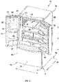
FIG. 2 provides a perspective view of the exemplary refrigerator appliance shown inFIG. 1 , wherein a refrigerator door is in an open position. -
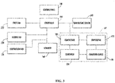
FIG. 3 provides a schematic view of various components of the exemplary refrigerator appliance shown inFIG. 1 . -
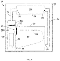
FIG. 4 provides a schematic view of a refrigerator appliance, illustrating a single-chamber cooling operation, according to exemplary embodiments of the present disclosure. -
FIG. 5 provides a schematic view of a refrigerator appliance, illustrating a common-chamber cooling operation, according to exemplary embodiments of the present disclosure. - Reference now will be made in detail to embodiments of the invention, one or more examples of which are illustrated in the drawings. Each example is provided by way of explanation of the invention, not limitation of the invention. In fact, it will be apparent to those skilled in the art that various modifications and variations can be made in the present invention without departing from the scope of the invention. For instance, features illustrated or described as part of one embodiment can be used with another embodiment to yield a still further embodiment. Thus, it is intended that the present invention covers such modifications and variations as come within the scope of the appended claims and their equivalents.
- As used herein, the term "or" is generally intended to be inclusive (i.e., "A or B" is intended to mean "A or B or both"). The terms "first," "second," and "third" may be used interchangeably to distinguish one component from another and are not intended to signify location or importance of the individual components. The terms "upstream" and "downstream" refer to the relative flow direction with respect to fluid flow (e.g., airflow or refrigerant flow) in a fluid pathway. For example, "upstream" refers to the flow direction from which the fluid flows, and "downstream" refers to the flow direction to which the fluid flows.
- Turning now to the figures,
FIGS. 1 provide perspective views of a refrigerator appliance (e.g., refrigerator appliance 100) according to exemplary embodiments of the present disclosure. Generally,refrigerator appliance 100 includes a cabinet orhousing 120 that extends between atop portion 101 and abottom portion 102 along a vertical direction V. Moreover,refrigerator appliance 100 defines multiple chilled chambers, such as for the receipt of food items for storage. For instance, one or moreinternal liners 112 are attached (e.g., fixedly attached) withinhousing 120 to define one or more discrete chilled chambers. In some embodiments, aliner 112 defines afresh food chamber 122 positioned at or adjacenttop portion 101 ofhousing 120, while a liner 112 (e.g., separate from or continuous with liner 112) defines afreezer chamber 124 arranged at oradjacent bottom portion 102 ofhousing 120. As such,refrigerator appliance 100 is generally referred to as a bottom mount refrigerator. - It is recognized, however, that the benefits of the present disclosure apply to other types and styles of refrigerator appliances such as, for example, a top mount refrigerator appliance, a side-by-side style refrigerator appliance or a standalone ice-maker appliance. Consequently, the description set forth herein is for illustrative purposes only and is not intended to be limiting in any aspect to any particular refrigerator chamber configuration.
-
Refrigerator doors 128 are rotatably hinged to an edge ofhousing 120 for selectively accessingfresh food chamber 122. In addition, afreezer door 130 is arranged belowrefrigerator doors 128 for selectively accessingfreezer chamber 124.Freezer door 130 is coupled to a freezer drawer (not shown) slidably mounted withinfreezer chamber 124.Refrigerator doors 128 andfreezer door 130 are shown in a closed configuration inFIG. 1 . - In some embodiments, various storage components are mounted within
fresh food chamber 122 to facilitate storage of food items therein, as will be understood art. In particular, the storage components includestorage bins 182,drawers 184, andshelves 186 that are mounted withinfresh food chamber 122.Storage bins 182,drawers 184, andshelves 186 are configured for receipt of food items (e.g., beverages or solid food items) and may assist with organizing such food items. As an example,drawers 184 can receive fresh food items (e.g., vegetables, fruits, or cheeses) and increase the useful life of such fresh food items. - In some embodiments,
refrigerator appliance 100 also includes a dispensingassembly 140 for dispensing liquid water or ice.Dispensing assembly 140 includes adispenser 142, for example, positioned on or mounted to an exterior portion of refrigerator appliance 100 (e.g., on one of doors 128).Dispenser 142 includes a dischargingoutlet 144 for accessing ice and liquid water. Anactuating mechanism 146, shown as a paddle, is mounted below dischargingoutlet 144 for operatingdispenser 142. In alternative exemplary embodiments, any suitable actuating mechanism may be used to operatedispenser 142. For example,dispenser 142 can include a sensor (such as an ultrasonic sensor) or a button rather than the paddle. Auser interface panel 148 is provided for controlling the mode of operation. For example,user interface panel 148 includes a plurality of user inputs (not labeled), such as a water dispensing button and an ice-dispensing button, for selecting a desired mode of operation such as crushed or non-crushed ice. - Discharging
outlet 144 andactuating mechanism 146 are an external part ofdispenser 142 and are mounted in adispenser recess 150.Dispenser recess 150 is positioned at a predetermined elevation convenient for a user to access ice or water and enabling the user to access ice without the need to bend-over and without the need to opendoors 128. In the exemplary embodiment,dispenser recess 150 is positioned at a level that approximates the chest level of a user. - In exemplary embodiments, a
secondary liner 114 is attached to cabinet 120 (e.g., by being mounted or fixed to door 128) and defines another chamber (e.g., sub-compartment 162) for the receipt or storage of one or more chilled items. For instance, in some embodiments, at least onedoor 128 includessecondary liner 114 positioned thereon. In turn, sub-compartment 162 may be defined within one ofdoors 128. In some such embodiments, sub-compartment 162 extends intofresh food chamber 122 whenrefrigerator door 128 is in the closed position. Althoughsub-compartment 162 is generally shown as being attached torefrigerator door 128, additional or alterative embodiments may include a sub-compartment defined at another portion of refrigerator appliance 100 (e.g., at a fixed location within fresh food chamber 122). - In some embodiments, an icemaker or
ice making assembly 160 and anice storage bin 164 are positioned or disposed withinsub-compartment 162. For instance,ice making assembly 160 may be positioned, at least in part, aboveice storage bin 164. During use, ice is supplied to dispenser recess 150 (FIG. 1 ) from theice making assembly 160 orice storage bin 164 insub-compartment 162 on a back side ofrefrigerator door 128. - In optional embodiments, an
access door 166 is hinged torefrigerator door 128.Access door 166 may permit selective access tosub-compartment 162. Any manner ofsuitable latch 168 is configured with sub-compartment 162 to maintainaccess door 166 in a closed position. As an example, latch 168 may be actuated by a user in order to openaccess door 166 for providing access intosub-compartment 162.Access door 166 can also assist with insulating sub-compartment 162 (e.g., by thermally isolating or insulating sub-compartment 162 from fresh food chamber 122). - In additional or alternative embodiments, liquid water generated during melting of ice cubes in
ice storage bin 164, is directed out ofice storage bin 164. For example, turning back toFIG. 1 , liquid water from melted ice cubes may be directed to anevaporation pan 172.Evaporation pan 172 is positioned within amechanical compartment 170 defined by housing 120 (e.g., atbottom portion 102 of housing 120). Acondenser 174 of the sealed system can be positioned above (e.g., directly above) and adjacent toevaporation pan 172. Heat fromcondenser 174 can assist with evaporation of liquid water inevaporation pan 172. Anevaporation fan 176 configured for coolingcondenser 174 can also direct a flow air across or intoevaporation pan 172. Thus,evaporation fan 176 can be positioned above andadjacent evaporation pan 172.Evaporation pan 172 is sized and shaped for facilitating evaporation of liquid water therein. For example,evaporation pan 172 may be open topped and extend across about a width or a depth ofhousing 120. - In some embodiments, chilled air from a sealed system 171 (
FIG. 3 ) ofrefrigerator appliance 100 may be directed through or to components within sub-compartment 162 (e.g.,ice making assembly 160 orstorage bin 164 assembly). For instance, sub-compartment 162 may exchange cooling air with a chilledair supply duct 165 and a chilledair return duct 167 disposed on a side portion ofcabinet 120 ofrefrigerator appliance 100, as will be further described below. In this manner, thesupply duct 165 and returnduct 167 may recirculate chilled air from a suitable sealedcooling system 171 throughsub-compartment 162. An air handler or fan (e.g., fan 234-FIG. 4 ) may be provided to motivate and recirculate air. As an example, the fan can direct chilled air from an evaporator 178 (e.g., that is mounted within anevaporator chamber 220 adjacent to or withinfood chamber 122 or freezer chamber 124) of a sealedsystem 171 throughsupply duct 165 tosub-compartment 162. -
FIG. 3 provides a schematic view of certain components ofrefrigerator appliance 100. As may be seen inFIG. 3 ,refrigerator appliance 100 includes a sealedcooling system 171 for executing a vapor compression cycle for cooling air within refrigerator appliance 100 (e.g., withinfresh food chamber 122,freezer chamber 124, and sub-compartment 162).Sealed cooling system 171 includes acompressor 180, acondenser 174, anexpansion device 181, and anevaporator 178 connected in fluid series and charged with a refrigerant. As will be understood by those skilled in the art, sealedcooling system 171 may include additional components (e.g., at least one additional evaporator, compressor, expansion device, or condenser). As an example, sealedcooling system 171 may include two evaporators. - Within sealed
cooling system 171, gaseous refrigerant flows intocompressor 180, which operates to increase the pressure of the refrigerant. This compression of the refrigerant raises its temperature, which is lowered by passing the gaseous refrigerant throughcondenser 174. Withincondenser 174, heat exchange with ambient air takes place so as to cool the refrigerant and cause the refrigerant to condense to a liquid state. - Expansion device 181 (e.g., a valve, capillary tube, or other restriction device) receives liquid refrigerant from
condenser 174. Fromexpansion device 181, the liquid refrigerant entersevaporator 178. Upon exitingexpansion device 181 and enteringevaporator 178, the liquid refrigerant drops in pressure and vaporizes. Due to the pressure drop and phase change of the refrigerant,evaporator 178 is cool relative to fresh food andfreezer chambers refrigerator appliance 100. As such, cooled air is produced and refrigerates fresh food andfreezer chambers refrigerator appliance 100. Thus,evaporator 178 is a heat exchanger which transfers heat from air passing overevaporator 178 to refrigerant flowing throughevaporator 178. -
Refrigerator appliance 100 also includes a pair of air handlers (e.g.,first fan 232 and a second fan 234). Generally,first fan 232 is operable to urge a flow of chilled air from theevaporator chamber 220 to thefreezer chamber 124.Second fan 234 is operable to urge another flow of chilled air from theevaporator chamber 220 to the sub-compartment 162 (e.g., via supply duct 165-FIG. 2 ) before flowing to the freezer chamber 124 (e.g., via return duct 167). Theair handlers air handlers - Referring generally to
FIGS. 1 through 3 , operation of therefrigerator appliance 100 can be regulated by acontroller 190 that is in operative communication withuser interface panel 148 or various other components, as will be described below.User interface panel 148 provides selections for user manipulation of the operation ofrefrigerator appliance 100 such as, for example, selections between whole or crushed ice, chilled water, or other various options. In response to user manipulation ofuser interface panel 148 or one or more sensor signals,controller 190 may operate various components of therefrigerator appliance 100.Controller 190 may include a memory and one or more microprocessors, CPUs or the like, such as general or special purpose microprocessors operable to execute programming instructions or micro-control code associated with operation ofrefrigerator appliance 100. The memory may represent random access memory such as DRAM, or read only memory such as ROM or FLASH. In one embodiment, the processor executes programming instructions stored in memory. The memory may be a separate component from the processor or may be included onboard within the processor. Alternatively,controller 190 may be constructed without using a microprocessor (e.g., using a combination of discrete analog or digital logic circuitry; such as switches, amplifiers, integrators, comparators, flip-flops, AND gates, and the like) to perform control functionality instead of relying upon software. -
Controller 190 may be positioned in a variety of locations throughoutrefrigerator appliance 100. In the illustrated embodiment,controller 190 is located adjacent to theuser interface panel 148. In other embodiments, thecontroller 190 may be positioned at any suitable location withinrefrigerator appliance 100, such as for example within a fresh food chamber, a freezer door, etc. Input/output ("I/O") signals may be routed betweencontroller 190 and various operational components ofrefrigerator appliance 100. For example,user interface panel 148 may be in operable communication (e.g., electrical communication or wireless communication) withcontroller 190 via one or more signal lines or shared communication busses. - As illustrated,
controller 190 may be in communication with the various components of dispensingassembly 140 and may control operation of the various components. For example, the various valves, switches, etc. may be actuatable based on commands from thecontroller 190. As discussed,interface panel 148 may additionally be in communication with thecontroller 190. Thus, the various operations may occur based on user input or automatically throughcontroller 190 instruction. - In optional embodiments,
controller 190 is further in operative communication with one ormore temperature sensors 240.Temperature sensors 240 can be any suitable device for measuring the temperature of an atmosphere or ambient air within refrigerator appliance 100 (e.g., withinsub-compartment 162,freezer chamber 124,fresh food chamber 122, etc.). For example, atemperature sensor 240 may include a thermistor or a thermocouple (e.g., mounted withinsub-compartment 162,freezer chamber 124,fresh food chamber 122, etc.).Controller 190 can receive a signal, such as a voltage or a current, from atemperature sensor 240 that corresponds to the temperature of the air within a corresponding chamber. In such a manner, the temperature of one or morechilled chambers controller 190. Optionally, one or more of thefans controller 190 to be activated based a received temperature signal (e.g., indicating temperature within a corresponding temperature has reached or exceeded a set chamber temperature). For instance,controller 190 may be configured to automatically and selectively initiate a single-chamber cooling operation or a common-chamber cooling operation to chill one or multiple chilled chambers, respectively. In some embodiments,controller 190 is configured to selectively initiate one of at least the single-chamber cooling operation and the common-chamber cooling operation based on, for instance, a temperature detected (e.g., at temperature sensors 240) at within thechilled chambers - Turning especially to
FIGS. 4 and5 , schematic views are provided ofrefrigerator appliance 100 operating in a single-chamber cooling operation (FIG. 4 ) and a common chamber cooling operation (FIG. 5 ) according to exemplary embodiments. As shown,refrigerator appliance 100 generally includes acabinet 120 defining anevaporator chamber 220. In addition,refrigerator appliance 100 includes afirst liner 212 andsecond liner 214 defining a discrete firstchilled chamber 222 and secondchilled chamber 224, respectively. In some embodiments, firstchilled chamber 222 includes or is provided as a freezer chamber 124 (e.g., defined by liner 112), as described above. In additional or alternative embodiments, secondchilled chamber 224 includes or is provided as sub-compartment 162 (e.g., defined by liner 114), as described above. Both thefirst liner 212 and thesecond liner 214 are attached to the cabinet 120 (e.g., directly or, alternatively, indirectly; such as through a refrigerator door 128-FIG. 2 ). As an example, thefirst liner 212 may be directly attached to and enclosed within the cabinet 120 (i.e., at a fixed location relative to cabinet 120), while thesecond liner 214 is directly attached or mounted to arefrigerator door 128, which is itself rotatably attached to thecabinet 120. Thus, thesecond liner 214 may rotate with thedoor 128. As an alternative example, both thefirst liner 212 may and thesecond liner 214 may be directly attached to and enclosed within the cabinet 120 (i.e., at separate fixed locations relative to cabinet 120). Optionally, thesecond liner 214 and secondchilled chamber 224 may be positioned above the firstchilled chamber 222. - As shown, first
chilled chamber 222 is arranged in fluid communication withevaporator chamber 220. Specifically, firstchilled chamber 222 can exchange air with the evaporator chamber 220 (and theevaporator 178 mounted therein) to selectively cool the air within firstchilled chamber 222. To facilitate air exchange, firstchilled chamber 222 has aprimary air inlet 242, asecondary air inlet 244, and anair outlet 246. - In some embodiments, the
primary air inlet 242 fluidly connects (e.g., directly connects) the firstchilled chamber 222 and theevaporator chamber 220. Theprimary air inlet 242 may be downstream from theevaporator chamber 220 and upstream from the firstchilled chamber 222. In additional or alternative embodiments, theair outlet 246 of the firstchilled chamber 222 further fluidly connects (e.g., directly connects) the firstchilled chamber 222 and theevaporator chamber 220. Theair outlet 246 may be downstream from the firstchilled chamber 222 and upstream from theevaporator chamber 220. In further additional or alternative embodiments, thesecondary air inlet 244 of the firstchilled chamber 222 may be spaced apart from theprimary air inlet 242 and theair outlet 246. In some such embodiments, thesecondary air inlet 244 only indirectly connects theevaporator chamber 220 to the first chilled chamber 222 (e.g., through the secondchilled chamber 224 or a return line 256). Thesecondary air inlet 244 of the firstchilled chamber 222 may be upstream from the firstchilled chamber 222 and in selective downstream fluid communication with theevaporator chamber 220. - Optionally,
evaporator chamber 220 may be positioned at a common height or in a larger enclosure that houses both theevaporator 178 and the firstchilled chamber 222 within thecabinet 120. Theprimary air inlet 242 and theair outlet 246 may be defined through a commonintermediate wall 258 separating or delineating theevaporator chamber 220 from the firstchilled chamber 222. Thesecondary air inlet 244 may be defined through a different wall and further spaced apart from theprimary air inlet 242 and the air outlet 246 (e.g., along the lateral direction or the transverse direction). - As shown, second
chilled chamber 224 is further arranged in fluid communication withevaporator chamber 220. In particular, secondchilled chamber 224 can exchange air with the evaporator chamber 220 (andevaporator 178 mounted therein) to selectively cool the air within secondchilled chamber 224. Thus,evaporator chamber 220 is a common cooling chamber selectively exchanging and mixing air between the firstchilled chamber 222 and the secondchilled chamber 224. - In some embodiments, the
air inlet 248 fluidly connects the secondchilled chamber 224 and theevaporator chamber 220. For instance, an intake line 254 (e.g., including or provided as supply duct 165-FIG. 2 ) fluidly connectsevaporator chamber 220 to theair inlet 248 of the secondchilled chamber 224. Theair inlet 248 may be downstream from the evaporator chamber 220 (and intake line 254) and upstream from the secondchilled chamber 224. In additional or alternative embodiments, theair outlet 252 of the secondchilled chamber 224 further fluidly connects the secondchilled chamber 224 and the firstchilled chamber 222. In particular, a return line 256 (e.g., including or provided as return duct 167-FIG. 2 ) extends in fluid communication from theair outlet 252 of the secondchilled chamber 224 to thesecondary air inlet 244 of the firstchilled chamber 222. Thus, air from the secondchilled chamber 224 may be selectively directed to the first chilled chamber 222 (and subsequently returned to the evaporator chamber 220) by passing through thereturn line 256. - In certain embodiments, the
return line 256 is unobstructed from the secondchilled chamber 224 to the firstchilled chamber 222. No portion of thereturn line 256 is selectively blocked or closed (e.g., by a damper). Thus, thereturn line 256 remains open and is physically unrestricted by any solid member along the fluid path between thechilled chambers 222, 224 (e.g., when allrefrigerator doors 128 are in the closed position). No moving part is provided to close or block theair outlet 252 of the secondchilled chamber 224 and thesecondary air inlet 244 of the firstchilled chamber 222. - In further embodiments, fluid communication between the evaporator 178, first
chilled chamber 222, secondchilled chamber 224, and returnline 256 is unobstructed and free of any movable damper. Thus, along with thereturn line 256 being unobstructed, as described above, theprimary air inlet 242 andair outlet 246 of the firstchilled chamber 222 may be unobstructed such that both remain open and physically unrestricted by any solid member along the fluid path between the firstchilled chamber 222 and theevaporator chamber 220. Moreover, theair inlet 248 of the secondchilled chamber 224 andintake line 254 may be unobstructed such that both remain open and physically unrestricted by any solid member along the fluid path between theevaporator chamber 220 and the secondchilled chamber 224. For theevaporator chamber 220, the firstchilled chamber 222, the secondchilled chamber 224, and thereturn line 256, there may be no moving part to close or block theprimary air inlet 242, thesecondary air inlet 244, theair outlet 246, theair inlet 248, and theair outlet 252. - As shown,
multiple fans chilled chambers 222, 224). Specifically, afirst fan 232 is in fluid communication with theevaporator chamber 220 and the firstchilled chamber 222, while asecond fan 234 is in fluid communication with theevaporator chamber 220 and the secondchilled chamber 224. Generally, eitherfan controller 190. For instance, eitherfan - In exemplary embodiments, the
first fan 232 is directed at theprimary air inlet 242. For instance, thefirst fan 232 may be positioned (e.g., physically and in fluid communication) between theevaporator chamber 220 and the firstchilled chamber 222 to motivate an airflow (e.g., airflow 262) accordingly. In such embodiments, firstchilled chamber 222 is a positive pressure chamber. Optionally, thefirst fan 232 is mounted within or proximate toprimary air inlet 242. - In additional or alternative embodiments, the
second fan 234 is directed at theair inlet 248 orintake line 254. For instance, thefirst fan 232 may be positioned (e.g., physically and in fluid communication) between theevaporator chamber 220 and theair inlet 248 or theintake line 254 to motivate an airflow (e.g., airflow 264) accordingly. In such embodiments, secondchilled chamber 224 is a positive pressure chamber. Optionally, thesecond fan 234 is mounted withinevaporator chamber 220. - Turning specifically to
FIG. 4 , an exemplary single-chamber cooling operation is illustrated. In particular, a first-fan (FF) coolingairflow 262 is initiated. Specifically, thefirst fan 232 is activated such that air is drawn from theevaporator chamber 220 and projected to the firstchilled chamber 222 through theprimary air inlet 242. For instance, thefirst fan 232 may be rotated at a FF rotation speed (e.g., first FF rotation speed provided as a predetermined rotations per minute of the first fan 232). Simultaneous to theFF cooling airflow 262, thesecond fan 234 is activated. The activation may be insufficient to generate an airflow to the secondchilled chamber 224 from thecommon evaporator chamber 220, but sufficient to generate a second-fan (SF) positive stagnation pressure. For instance, thesecond fan 234 may be rotated at a SF rotation speed (e.g., first SF rotation speed provided as a predetermined rotations per minute of the second fan 234). The first SF rotation speed may be tuned according to the first FF rotation speed, such that the SF positive pressure matches the pressure within the firstchilled chamber 222 without overcoming the negative pressure generated by the first FF rotation speed. Although the SF positive stagnation pressure is insufficient to force air from theevaporator chamber 220 to the secondchilled chamber 224 against the negative pressure generated within theevaporator chamber 220 by thefirst fan 232, the secondchilled chamber 224 and returnline 256 may be positively pressured. Air within the secondchilled chamber 224 may be contained therein. Moreover, a backflow (e.g., through the return line 256) from the firstchilled chamber 222 to the second chilled chamber 224 (and then to the evaporator chamber 220) is prevented. Notably, such a backflow would otherwise be generated by the disparity in pressure between firstchilled chamber 222 and the secondchilled chamber 224. Advantageously, theFF cooling airflow 262 may continue to cool the firstchilled chamber 222 without influencing the temperature within the secondchilled chamber 224 or requiring any portion of the flow path through the secondchilled chamber 224 from theevaporator chamber 220 to thesecondary air inlet 244 to be blocked (e.g., by a solid damper). - Turning specifically to
FIG. 5 , an exemplary common-chamber cooling operation is illustrated. In particular,FF cooling airflow 262 is initiated. Specifically, thefirst fan 232 is activated such that air is drawn from theevaporator chamber 220 and projected to the firstchilled chamber 222 through theprimary air inlet 242. For instance, thefirst fan 232 may be rotated at a FF rotation speed (e.g., second FF rotation speed provided as a predetermined rotations per minute of the first fan 232). Simultaneous to theFF cooling airflow 262, aSF cooling airflow 264 is initiated. Specifically, thesecond fan 234 is activated such that air is drawn from theevaporator chamber 220 and projected to the secondchilled chamber 224 through theair inlet 248. For instance, thesecond fan 234 may be rotated at a SF rotation speed (e.g., second SF rotation speed provided as a predetermined rotations per minute of the second fan 234). Generally, the second SF rotation speed is greater than the first SF rotation speed. The second SF rotation speed may be tuned according to the second FF rotation speed, such that theSF airflow 264 is initiated in spite of the negative pressure generated by the second FF rotation speed. Air may thus be forced downstream to the firstchilled chamber 222 and the secondchilled chamber 224 in parallel before being returned to theevaporator chamber 220 through the firstchilled chamber 222 andair outlet 246. Advantageously, theFF cooling airflow 262 andSF cooling airflow 264 may simultaneously cool the firstchilled chamber 222 and the secondchilled chamber 224, respectively, using acommon evaporator 178 andevaporator chamber 220. - This written description uses examples to disclose the invention, including the best mode, and also to enable any person skilled in the art to practice the invention, including making and using any devices or systems and performing any incorporated methods. The patentable scope of the invention is defined by the claims, and may include other examples that occur to those skilled in the art. Such other examples are intended to be within the scope of the claims if they include structural elements that do not differ from the literal language of the claims, or if they include equivalent structural elements with insubstantial differences from the literal languages of the claims.
Claims (18)
- A refrigerator appliance (100) comprising:a cabinet (120) defining an evaporator chamber (220);a first liner (212) attached to the cabinet (120) and defining a first chilled chamber (222) having a primary air inlet (242), a secondary air inlet (244), and an air outlet (246);a second liner (214) attached to the cabinet (120) and defining a second chilled chamber (224) spaced apart from the first chilled chamber (222), the second chilled chamber (224) having an air inlet and an air outlet (246);a first fan (232) in fluid communication with the evaporator chamber (220) and the first chilled chamber (222);a second fan (234) in fluid communication with the evaporator chamber (220) and the second chilled chamber (224); anda return line (256) extending in fluid communication from the air outlet (246) of the second chilled chamber (224) to the secondary air inlet (244) of the first chilled chamber (222).
- The refrigerator appliance (100) of claim 1, wherein the return line (256) is unobstructed from the second chilled chamber (224) to the first chilled chamber (222).
- The refrigerator appliance (100) of claim 1, wherein fluid communication between the evaporator chamber (220), the first chilled chamber (222), the second chilled chamber (224), and the return line (256) is unobstructed and free of any movable damper.
- The refrigerator appliance (100) of claim 1, further comprising a controller (190) in operative communication with the first fan (232) and the second fan (234), the controller (190) being configured to initiate a common-chamber cooling operation, the common-chamber cooling operation comprisingactivating the first fan (232) to motivate a first-fan (FF) cooling airflow (262) from the evaporator chamber (220) to the first chilled chamber (222), andactivating the second fan (234) to motivate a second-fan (SF) cooling airflow (264) from the evaporator chamber (220) to the second chilled chamber (224) during motivation of the FF cooling airflow (262).
- The refrigerator appliance (100) of claim 1, further comprising a controller (190) in operative communication with the first fan (232) and the second fan (234), the controller (190) being configured to initiate a single-chamber cooling operation, the single-chamber cooling operation comprising
activating the second fan (234) to generate a second-fan (SF) positive stagnation pressure from the evaporator chamber (220), through the second chilled chamber (224), and to the secondary air inlet (244) of the first chilled chamber (222), the SF positive stagnation pressure preventing an airflow through the return line (256). - The refrigerator appliance (100) of claim 1, wherein the air outlet (246) of the first chilled chamber (222) fluidly connects the first chilled chamber (222) and the evaporator chamber (220).
- The refrigerator appliance (100) of claim 1, wherein the primary air inlet (242) of the first chilled chamber (222) fluidly connects the evaporator chamber (220) and the first chilled chamber (222).
- The refrigerator appliance (100) of claim 1, wherein the evaporator chamber (220) defines a mixing volume permitting communication from the fluid outlet of the first chilled chamber (222) to the air inlet of the second chilled chamber (224).
- The refrigerator appliance (100) of claim 1, further comprising a door (128) rotatably attached to the cabinet (120), wherein the second liner (214) is mounted to the door (128) to rotate therewith.
- The refrigerator appliance (100) of claim 1, wherein the second liner (214) is mounted to the cabinet (120) at a fixed location relative to the evaporator chamber (220).
- A refrigerator appliance (100) comprising:a cabinet (120) defining an evaporator chamber (220);a first liner (212) attached to the cabinet (120) and defining a first chilled chamber (222) having a primary air inlet (242), a secondary air inlet (244), and an air outlet (246);a second liner (214) attached to the cabinet (120) and defining a second chilled chamber (224) spaced apart from the first chilled chamber (222), the second chilled chamber (224) having an air inlet and an air outlet (246);a first fan (232) in fluid communication with the evaporator chamber (220) and the first chilled chamber (222);a second fan (234) in fluid communication with the evaporator chamber (220) and the second chilled chamber (224);a return line (256) extending in fluid communication from the air outlet (246) of the second chilled chamber (224) to the secondary air inlet (244) of the first chilled chamber (222), the return line (256) being unobstructed from the second chilled chamber (224) to the first chilled chamber (222); anda controller (190) in operative communication with the first fan (232) and the second fan (234), the controller (190) being configured to initiate a single-chamber cooling operation, the single-chamber cooling operation comprisingactivating the first fan (232) to motivate a first-fan (FF) cooling airflow from the evaporator chamber (220) to the first chilled chamber (222), andactivating the second fan (234) to generate a second-fan (SF) positive stagnation pressure from the evaporator chamber (220), through the second chilled chamber (224), and to the secondary air inlet (244) of the first chilled chamber (222), the SF positive stagnation pressure preventing an airflow through the return line (256).
- The refrigerator appliance (100) of claim 11, wherein fluid communication between the evaporator chamber (220), the first chilled chamber (222), the second chilled chamber (224), and the return line (256) is unobstructed and free of any movable damper.
- The refrigerator appliance (100) of claim 11, wherein the controller (190) is further configured to initiate a common-chamber cooling operation separate from the single-chamber cooling operation, the common-chamber cooling operation comprisingactivating the first fan (232) to motivate a first-fan (FF) cooling airflow from the evaporator chamber (220) to the first chilled chamber (222), andactivating the second fan (234) to motivate a second-fan (SF) cooling airflow (264) from the evaporator chamber (220) to the second chilled chamber (224) during motivation of the FF cooling airflow (262).
- The refrigerator appliance (100) of claim 11, wherein the air outlet (246) of the first chilled chamber (222) fluidly connects the first chilled chamber (222) and the evaporator chamber (220).
- The refrigerator appliance (100) of claim 11, wherein the primary air inlet (242) of the first chilled chamber (222) fluidly connects the evaporator chamber (220) and the first chilled chamber (222).
- The refrigerator appliance (100) of claim 11, wherein the evaporator chamber (220) defines a mixing volume permitting communication from the fluid outlet of the first chilled chamber (222) to the air inlet of the second chilled chamber (224).
- The refrigerator appliance (100) of claim 11, further comprising a door (128) rotatably attached to the cabinet (120), wherein the second liner (214) is mounted to the door (128) to rotate therewith.
- The refrigerator appliance (100) of claim 11, wherein the second liner (214) is mounted to the cabinet (120) at a fixed location relative to the evaporator chamber (220).
Applications Claiming Priority (2)
| Application Number | Priority Date | Filing Date | Title |
|---|---|---|---|
| US16/547,939 US11079160B2 (en) | 2019-08-22 | 2019-08-22 | Refrigerator appliances having multiple fluidly-connected, chilled chambers |
| PCT/CN2020/110423 WO2021032182A1 (en) | 2019-08-22 | 2020-08-21 | Cooling appliance having multiple cooling compartments in fluid communication with each other |
Publications (2)
| Publication Number | Publication Date |
|---|---|
| EP4019865A1 true EP4019865A1 (en) | 2022-06-29 |
| EP4019865A4 EP4019865A4 (en) | 2022-10-05 |
Family
ID=74645305
Family Applications (1)
| Application Number | Title | Priority Date | Filing Date |
|---|---|---|---|
| EP20855557.3A Withdrawn EP4019865A4 (en) | 2019-08-22 | 2020-08-21 | REFRIGERATION APPLIANCE HAVING SEVERAL REFRIGERATION COMPARTMENTS IN FLUID COMMUNICATION |
Country Status (4)
| Country | Link |
|---|---|
| US (1) | US11079160B2 (en) |
| EP (1) | EP4019865A4 (en) |
| CN (1) | CN114270121A (en) |
| WO (1) | WO2021032182A1 (en) |
Families Citing this family (5)
| Publication number | Priority date | Publication date | Assignee | Title |
|---|---|---|---|---|
| US11402145B1 (en) * | 2020-03-24 | 2022-08-02 | Sub-Zero Group, Inc. | Split air flow system |
| JP7637082B2 (en) * | 2022-02-02 | 2025-02-27 | 日立グローバルライフソリューションズ株式会社 | refrigerator |
| US12498165B2 (en) | 2022-08-16 | 2025-12-16 | Hoshizaki America, Inc. | Refrigerated appliance with ducted air flow |
| US12571583B2 (en) * | 2022-08-16 | 2026-03-10 | Hoshizaki America, Inc. | Refrigerated appliance with automatically adjustable setpoint |
| US20250314414A1 (en) * | 2024-04-08 | 2025-10-09 | Haier Us Appliance Solutions, Inc. | Method of cooling a deli pan in a refrigerator appliance |
Family Cites Families (12)
| Publication number | Priority date | Publication date | Assignee | Title |
|---|---|---|---|---|
| US3107502A (en) * | 1961-04-24 | 1963-10-22 | Whirlpool Co | Air circuit means for combined freezer and refrigerator apparatus |
| JPH0749905B2 (en) * | 1987-01-28 | 1995-05-31 | オリオン機械株式会社 | Fresh food storage device |
| US5899083A (en) | 1997-03-12 | 1999-05-04 | Whirlpool Corporation | Multi-compartment refrigeration system |
| CN2602326Y (en) * | 2003-01-11 | 2004-02-04 | 海尔集团公司 | Air-cooled refrigerator with a built-in freezing chamber |
| JP2006250423A (en) * | 2005-03-10 | 2006-09-21 | Matsushita Electric Ind Co Ltd | refrigerator |
| US7337620B2 (en) * | 2005-05-18 | 2008-03-04 | Whirlpool Corporation | Insulated ice compartment for bottom mount refrigerator |
| PL2413074T3 (en) * | 2010-07-26 | 2013-09-30 | Electrolux Home Products Corp Nv | Multi-compartment refrigerating apparatus for storing fresh food at different temperatures |
| KR20130073543A (en) | 2011-12-23 | 2013-07-03 | 엘지전자 주식회사 | Refrigerator |
| CN102980344B (en) * | 2012-12-28 | 2014-12-17 | 合肥美的电冰箱有限公司 | Refrigerator |
| CN204359028U (en) * | 2014-12-04 | 2015-05-27 | 海信容声(广东)冰箱有限公司 | A kind of refrigerator |
| CN105698466A (en) * | 2016-04-22 | 2016-06-22 | 合肥华凌股份有限公司 | Refrigerator with ice-making chamber |
| CN108332478A (en) * | 2017-12-22 | 2018-07-27 | 青岛海尔股份有限公司 | Refrigerator |
-
2019
- 2019-08-22 US US16/547,939 patent/US11079160B2/en active Active
-
2020
- 2020-08-21 WO PCT/CN2020/110423 patent/WO2021032182A1/en not_active Ceased
- 2020-08-21 EP EP20855557.3A patent/EP4019865A4/en not_active Withdrawn
- 2020-08-21 CN CN202080059110.9A patent/CN114270121A/en active Pending
Also Published As
| Publication number | Publication date |
|---|---|
| US20210055032A1 (en) | 2021-02-25 |
| US11079160B2 (en) | 2021-08-03 |
| EP4019865A4 (en) | 2022-10-05 |
| WO2021032182A1 (en) | 2021-02-25 |
| CN114270121A (en) | 2022-04-01 |
Similar Documents
| Publication | Publication Date | Title |
|---|---|---|
| US11079160B2 (en) | Refrigerator appliances having multiple fluidly-connected, chilled chambers | |
| US10352610B2 (en) | Refrigerator appliance | |
| US10240842B2 (en) | Ice making appliance and apparatus | |
| JP6254404B2 (en) | Shielding device and refrigerator having the same | |
| US10323874B2 (en) | Attachment system for an ice maker | |
| US10408524B2 (en) | System and method for controlling the temperature of a temperature controlled drawer | |
| RU2498169C2 (en) | Refrigerating device | |
| US20210033332A1 (en) | Refrigerator appliance having a plurality of evaporators for cooling separate chambers | |
| US10281190B2 (en) | Refrigerator appliance with dual freezer compartments | |
| US20190063817A1 (en) | Refrigerator appliance | |
| US20170332658A1 (en) | Refrigerator Appliance and Frozen Beverage Unit | |
| US11009277B2 (en) | Refrigator applicances having a removable ice storage bin | |
| US10465967B2 (en) | Refrigerator appliance with a convertible freezer compartment | |
| US10288340B2 (en) | Refrigerator appliance with dual freezer compartments | |
| US10527339B2 (en) | Refrigerator appliance | |
| US10274242B2 (en) | Refrigerator appliance with dual freezer compartments | |
| AU2021252970B2 (en) | Refrigeration appliance having ice making and distribution system | |
| US11918009B2 (en) | Refrigerator appliance having one or more incorporated features for making ice cream | |
| US20260022865A1 (en) | Refrigerator appliance dual flow refrigerant decoupling | |
| CN221527012U (en) | refrigerator | |
| US20250297797A1 (en) | Refrigerator appliance having a sealed system with supplemental heat features and methods of operation | |
| US20250297796A1 (en) | Refrigerator appliance having a dual-flow sealed system and methods of operating the same | |
| US11598576B2 (en) | Refrigerator appliance with mixing dispenser | |
| US10544979B2 (en) | Appliance and method of controlling the appliance | |
| JPH03137476A (en) | Refrigerator |
Legal Events
| Date | Code | Title | Description |
|---|---|---|---|
| STAA | Information on the status of an ep patent application or granted ep patent |
Free format text: STATUS: THE INTERNATIONAL PUBLICATION HAS BEEN MADE |
|
| PUAI | Public reference made under article 153(3) epc to a published international application that has entered the european phase |
Free format text: ORIGINAL CODE: 0009012 |
|
| STAA | Information on the status of an ep patent application or granted ep patent |
Free format text: STATUS: REQUEST FOR EXAMINATION WAS MADE |
|
| 17P | Request for examination filed |
Effective date: 20220222 |
|
| AK | Designated contracting states |
Kind code of ref document: A1 Designated state(s): AL AT BE BG CH CY CZ DE DK EE ES FI FR GB GR HR HU IE IS IT LI LT LU LV MC MK MT NL NO PL PT RO RS SE SI SK SM TR |
|
| REG | Reference to a national code |
Ref country code: DE Ref legal event code: R079 Free format text: PREVIOUS MAIN CLASS: F25D0011020000 Ipc: F25D0017060000 |
|
| A4 | Supplementary search report drawn up and despatched |
Effective date: 20220902 |
|
| RIC1 | Information provided on ipc code assigned before grant |
Ipc: F25D 17/06 20060101AFI20220829BHEP |
|
| DAV | Request for validation of the european patent (deleted) | ||
| DAX | Request for extension of the european patent (deleted) | ||
| GRAP | Despatch of communication of intention to grant a patent |
Free format text: ORIGINAL CODE: EPIDOSNIGR1 |
|
| STAA | Information on the status of an ep patent application or granted ep patent |
Free format text: STATUS: GRANT OF PATENT IS INTENDED |
|
| INTG | Intention to grant announced |
Effective date: 20240906 |
|
| STAA | Information on the status of an ep patent application or granted ep patent |
Free format text: STATUS: THE APPLICATION IS DEEMED TO BE WITHDRAWN |
|
| 18D | Application deemed to be withdrawn |
Effective date: 20250108 |