EP4019811A1 - Hydraulic transmission system with configurable virtual gears - Google Patents
Hydraulic transmission system with configurable virtual gears Download PDFInfo
- Publication number
- EP4019811A1 EP4019811A1 EP21216692.0A EP21216692A EP4019811A1 EP 4019811 A1 EP4019811 A1 EP 4019811A1 EP 21216692 A EP21216692 A EP 21216692A EP 4019811 A1 EP4019811 A1 EP 4019811A1
- Authority
- EP
- European Patent Office
- Prior art keywords
- speed
- hydraulic
- volume
- motor
- work vehicle
- Prior art date
- Legal status (The legal status is an assumption and is not a legal conclusion. Google has not performed a legal analysis and makes no representation as to the accuracy of the status listed.)
- Granted
Links
Images



Classifications
-
- F—MECHANICAL ENGINEERING; LIGHTING; HEATING; WEAPONS; BLASTING
- F16—ENGINEERING ELEMENTS AND UNITS; GENERAL MEASURES FOR PRODUCING AND MAINTAINING EFFECTIVE FUNCTIONING OF MACHINES OR INSTALLATIONS; THERMAL INSULATION IN GENERAL
- F16H—GEARING
- F16H61/00—Control functions within control units of change-speed- or reversing-gearings for conveying rotary motion ; Control of exclusively fluid gearing, friction gearing, gearings with endless flexible members or other particular types of gearing
- F16H61/66—Control functions within control units of change-speed- or reversing-gearings for conveying rotary motion ; Control of exclusively fluid gearing, friction gearing, gearings with endless flexible members or other particular types of gearing specially adapted for continuously variable gearings
-
- E—FIXED CONSTRUCTIONS
- E02—HYDRAULIC ENGINEERING; FOUNDATIONS; SOIL SHIFTING
- E02F—DREDGING; SOIL-SHIFTING
- E02F9/00—Component parts of dredgers or soil-shifting machines, not restricted to one of the kinds covered by groups E02F3/00 - E02F7/00
- E02F9/20—Drives; Control devices
- E02F9/22—Hydraulic or pneumatic drives
- E02F9/2221—Control of flow rate; Load sensing arrangements
- E02F9/2232—Control of flow rate; Load sensing arrangements using one or more variable displacement pumps
- E02F9/2235—Control of flow rate; Load sensing arrangements using one or more variable displacement pumps including an electronic controller
-
- E—FIXED CONSTRUCTIONS
- E02—HYDRAULIC ENGINEERING; FOUNDATIONS; SOIL SHIFTING
- E02F—DREDGING; SOIL-SHIFTING
- E02F9/00—Component parts of dredgers or soil-shifting machines, not restricted to one of the kinds covered by groups E02F3/00 - E02F7/00
- E02F9/20—Drives; Control devices
- E02F9/22—Hydraulic or pneumatic drives
- E02F9/2253—Controlling the travelling speed of vehicles, e.g. adjusting travelling speed according to implement loads, control of hydrostatic transmission
-
- E—FIXED CONSTRUCTIONS
- E02—HYDRAULIC ENGINEERING; FOUNDATIONS; SOIL SHIFTING
- E02F—DREDGING; SOIL-SHIFTING
- E02F9/00—Component parts of dredgers or soil-shifting machines, not restricted to one of the kinds covered by groups E02F3/00 - E02F7/00
- E02F9/20—Drives; Control devices
- E02F9/22—Hydraulic or pneumatic drives
- E02F9/2278—Hydraulic circuits
- E02F9/2292—Systems with two or more pumps
-
- E—FIXED CONSTRUCTIONS
- E02—HYDRAULIC ENGINEERING; FOUNDATIONS; SOIL SHIFTING
- E02F—DREDGING; SOIL-SHIFTING
- E02F9/00—Component parts of dredgers or soil-shifting machines, not restricted to one of the kinds covered by groups E02F3/00 - E02F7/00
- E02F9/20—Drives; Control devices
- E02F9/22—Hydraulic or pneumatic drives
- E02F9/2278—Hydraulic circuits
- E02F9/2296—Systems with a variable displacement pump
-
- E—FIXED CONSTRUCTIONS
- E02—HYDRAULIC ENGINEERING; FOUNDATIONS; SOIL SHIFTING
- E02F—DREDGING; SOIL-SHIFTING
- E02F9/00—Component parts of dredgers or soil-shifting machines, not restricted to one of the kinds covered by groups E02F3/00 - E02F7/00
- E02F9/26—Indicating devices
- E02F9/264—Sensors and their calibration for indicating the position of the work tool
-
- F—MECHANICAL ENGINEERING; LIGHTING; HEATING; WEAPONS; BLASTING
- F16—ENGINEERING ELEMENTS AND UNITS; GENERAL MEASURES FOR PRODUCING AND MAINTAINING EFFECTIVE FUNCTIONING OF MACHINES OR INSTALLATIONS; THERMAL INSULATION IN GENERAL
- F16H—GEARING
- F16H61/00—Control functions within control units of change-speed- or reversing-gearings for conveying rotary motion ; Control of exclusively fluid gearing, friction gearing, gearings with endless flexible members or other particular types of gearing
- F16H61/38—Control of exclusively fluid gearing
- F16H61/40—Control of exclusively fluid gearing hydrostatic
- F16H61/46—Automatic regulation in accordance with output requirements
- F16H61/462—Automatic regulation in accordance with output requirements for achieving a target speed ratio
-
- E—FIXED CONSTRUCTIONS
- E02—HYDRAULIC ENGINEERING; FOUNDATIONS; SOIL SHIFTING
- E02F—DREDGING; SOIL-SHIFTING
- E02F3/00—Dredgers; Soil-shifting machines
- E02F3/04—Dredgers; Soil-shifting machines mechanically-driven
- E02F3/28—Dredgers; Soil-shifting machines mechanically-driven with digging tools mounted on a dipper- or bucket-arm, i.e. there is either one arm or a pair of arms, e.g. dippers, buckets
- E02F3/36—Component parts
- E02F3/42—Drives for dippers, buckets, dipper-arms or bucket-arms
- E02F3/43—Control of dipper or bucket position; Control of sequence of drive operations
- E02F3/431—Control of dipper or bucket position; Control of sequence of drive operations for bucket-arms, front-end loaders, dumpers or the like
-
- F—MECHANICAL ENGINEERING; LIGHTING; HEATING; WEAPONS; BLASTING
- F16—ENGINEERING ELEMENTS AND UNITS; GENERAL MEASURES FOR PRODUCING AND MAINTAINING EFFECTIVE FUNCTIONING OF MACHINES OR INSTALLATIONS; THERMAL INSULATION IN GENERAL
- F16H—GEARING
- F16H61/00—Control functions within control units of change-speed- or reversing-gearings for conveying rotary motion ; Control of exclusively fluid gearing, friction gearing, gearings with endless flexible members or other particular types of gearing
- F16H61/66—Control functions within control units of change-speed- or reversing-gearings for conveying rotary motion ; Control of exclusively fluid gearing, friction gearing, gearings with endless flexible members or other particular types of gearing specially adapted for continuously variable gearings
- F16H2061/6604—Special control features generally applicable to continuously variable gearings
- F16H2061/6615—Imitating a stepped transmissions
-
- F—MECHANICAL ENGINEERING; LIGHTING; HEATING; WEAPONS; BLASTING
- F16—ENGINEERING ELEMENTS AND UNITS; GENERAL MEASURES FOR PRODUCING AND MAINTAINING EFFECTIVE FUNCTIONING OF MACHINES OR INSTALLATIONS; THERMAL INSULATION IN GENERAL
- F16H—GEARING
- F16H61/00—Control functions within control units of change-speed- or reversing-gearings for conveying rotary motion ; Control of exclusively fluid gearing, friction gearing, gearings with endless flexible members or other particular types of gearing
- F16H61/38—Control of exclusively fluid gearing
- F16H61/40—Control of exclusively fluid gearing hydrostatic
- F16H61/42—Control of exclusively fluid gearing hydrostatic involving adjustment of a pump or motor with adjustable output or capacity
- F16H61/421—Motor capacity control by electro-hydraulic control means, e.g. using solenoid valves
-
- F—MECHANICAL ENGINEERING; LIGHTING; HEATING; WEAPONS; BLASTING
- F16—ENGINEERING ELEMENTS AND UNITS; GENERAL MEASURES FOR PRODUCING AND MAINTAINING EFFECTIVE FUNCTIONING OF MACHINES OR INSTALLATIONS; THERMAL INSULATION IN GENERAL
- F16H—GEARING
- F16H61/00—Control functions within control units of change-speed- or reversing-gearings for conveying rotary motion ; Control of exclusively fluid gearing, friction gearing, gearings with endless flexible members or other particular types of gearing
- F16H61/38—Control of exclusively fluid gearing
- F16H61/40—Control of exclusively fluid gearing hydrostatic
- F16H61/42—Control of exclusively fluid gearing hydrostatic involving adjustment of a pump or motor with adjustable output or capacity
- F16H61/431—Pump capacity control by electro-hydraulic control means, e.g. using solenoid valves
-
- F—MECHANICAL ENGINEERING; LIGHTING; HEATING; WEAPONS; BLASTING
- F16—ENGINEERING ELEMENTS AND UNITS; GENERAL MEASURES FOR PRODUCING AND MAINTAINING EFFECTIVE FUNCTIONING OF MACHINES OR INSTALLATIONS; THERMAL INSULATION IN GENERAL
- F16H—GEARING
- F16H61/00—Control functions within control units of change-speed- or reversing-gearings for conveying rotary motion ; Control of exclusively fluid gearing, friction gearing, gearings with endless flexible members or other particular types of gearing
- F16H61/38—Control of exclusively fluid gearing
- F16H61/40—Control of exclusively fluid gearing hydrostatic
- F16H61/44—Control of exclusively fluid gearing hydrostatic with more than one pump or motor in operation
Definitions
- a hydraulic system may include a hydraulic pump that pressurizes a hydraulic fluid to generate a pressurized hydraulic fluid, which may then be used to perform various tasks.
- a work vehicle e.g., an agricultural vehicle and/or a construction vehicle, such as a skid steer
- the pressurized hydraulic fluid may be used to actuate a hydraulic motor that generates rotational power to drive one or more wheels of the work vehicle.
- a hydraulic system for a work vehicle includes a hydraulic motor configured to generate rotational power for one or more wheels on the work vehicle.
- the hydraulic system also includes a hydraulic pump coupled to the hydraulic motor, wherein the hydraulic pump is configured to pump hydraulic fluid to the hydraulic motor.
- the hydraulic control system includes a processor that is configured to receive an input indicative of a selection of a number of speed ranges that span between a minimum speed and a maximum speed for the work vehicle and to provide a motor command to set a motor volume of the hydraulic motor and a pump command to set a limit for a pump volume of the hydraulic pump to enable the number of speed ranges for the work vehicle.
- a hydraulic control system for a work vehicle includes a processor that is configured to receive a configuration input from an operator indicative of a selection of a first number of speed ranges that span between a minimum speed and a maximum speed for the work vehicle.
- the processor is also configured to receive a first shift input from the operator indicative of a request to shift to a first speed range of the first number of speed ranges.
- the processor is further configured to provide a pump command to set a limit for a pump volume to a first limit to enable the first speed range of the first number of speed ranges.
- a method of operating a hydraulic system for a work vehicle includes receiving, at one or more processors, an input indicative of a selection of a first number of speed ranges that span between a minimum speed and a maximum speed for the work vehicle.
- the method includes adjusting, using the one or more processors, a motor volume of a hydraulic motor, a limit for a pump volume of a hydraulic pump, or both to enable the number of speed ranges.
- the method also includes receiving, at the one or more processors, an additional input indicative of an additional selection of a second number of speed ranges that span between the minimum speed and the maximum speed for the work vehicle.
- the method further includes adjusting, using the one or more processors, the motor volume of the hydraulic motor and the limit for the pump volume of the hydraulic pump to enable the second number of speed ranges.
- Work vehicles may include one or more hydraulic systems that provide power to complete various tasks. These various tasks may include loading, lifting, pushing, rotating, dozing, and/or moving the work vehicle.
- a work vehicle may include a hydraulic system that includes one or more hydraulic motors that drive wheels of the work vehicle. The wheels in turn couple to tracks, which enable the work vehicle to traverse various types of terrain. An operator may want to adjust a speed range for the work vehicle depending on the task and/or the terrain.
- the operator may provide a shifting command via one or more input devices (e.g., a switch).
- the shifting command may cause the hydraulic system to increase or to decrease a hydraulic motor volume of the one or more hydraulic motors.
- the shifting command may cause the hydraulic system to adjust each of the hydraulic motors from a first motor volume (e.g., a higher volume; for the first, lower speed range) to a second motor volume (e.g., a lower volume; for the second, higher speed range).
- the operator may provide a drive command via one or more input devices (e.g., a joystick) to adjust a flow rate of hydraulic fluid from one or more hydraulic pumps to the one or more hydraulic motors that have the second motor volume.
- the change to the motor volume from the first motor volume to the second motor volume causes the motor speed to increase to allow the hydraulic fluid (e.g., at the particular flow rate) to pass through the second motor volume.
- the present disclosure relates generally to a hydraulic system (e.g., configurable hydraulic system) that includes configurable virtual gears (e.g., pseudo gears; gear ratios) to enable the operator to establish any number of speed ranges (e.g., 1, 2, 3, 4, 5, 6 or more) for the work vehicle.
- the operator may select (e.g., via a graphical user interface displayed in the work vehicle) a number of virtual gears that are overlaid onto (e.g., used together with) mechanical gears (e.g., hydro-mechanical gears; gear ratios) to provide a total number of gears and corresponding speed ranges for the work vehicle.
- the operator may select two virtual gears that are overlaid onto two mechanical gears (e.g., the two mechanical gears that would provide two speed ranges without the virtual gears) to provide a total of four gears and four speed ranges for the work vehicle.
- each of the gears corresponds to a respective speed range for the work vehicle, and thus, the terms "gears" and "speed ranges" may be used to describe operational features of the hydraulic system.
- a minimum speed and a maximum speed for the work vehicle may be unchanged by the addition of the virtual gears.
- the number of speed ranges provided between may vary to provide varying levels of control (e.g., finer control options with a higher number of speed ranges, as opposed to only coarser control options with a lower number of speed ranges) using the one or more input devices (e.g., the joystick).
- levels of control e.g., finer control options with a higher number of speed ranges, as opposed to only coarser control options with a lower number of speed ranges
- FIG. 1 is a side view of an embodiment of a work vehicle 10 (e.g., a skid steer).
- the work vehicle 10 may include wheels 11 and tracks 12 that enable the work vehicle 10 to move.
- the work vehicle 10 includes an engine 14 that provides power to a hydraulic system 16.
- the hydraulic system 16 in turn provides power to the wheels 11, which then rotate the tracks 12.
- the hydraulic system 16 may also provide power to other systems on the work vehicle 10.
- the hydraulic system 16 may provide power to hydraulic actuators 18 (e.g., hydraulic cylinders) that control operation of one or more arms 20 (e.g., booms).
- the arms 20 couple to a tool 22 that enable the work vehicle 10 to perform various tasks.
- the tool 22 may be a fork, bucket, plow, blade, among others.
- the tool 22 is a bucket that enables the work vehicle 10 to perform loading tasks.
- the tool 22 may instead be (e.g., changed to) a blade to perform dozing tasks and/or the tool 22 may instead be (e.g., changed to) another type of tool for another type of task.
- the hydraulic system 16 may include one or more hydraulic pumps and one or more hydraulic motors that provide power to the wheels 11 on the work vehicle 10.
- the work vehicle 10 includes a hydraulic control system 24.
- the hydraulic control system 24 controls operation of the one or more hydraulic pumps and the one or more hydraulic motors on the work vehicle 10 based on various inputs from the operator to provide the number of speed ranges selected by the operator.
- the operator may utilize one or more input devices 26 (e.g., touchscreen display, knobs, switches, joystick) within a cab 28 of the work vehicle 10 to provide the various inputs.
- the operator may utilize one of the input devices 26 (e.g., touchscreen display) to provide the various inputs to set the number of speed ranges.
- the operator may utilize one of the input devices 26 (e.g., switch) to switch between the speed ranges, and the operator may utilize one of the input devices 26 (e.g., joystick) to adjust a flow rate of hydraulic fluid from the one or more hydraulic pumps to the one or more motors to thereby adjust the speed within a current speed range.
- FIG. 2 is a schematic diagram of an embodiment of the hydraulic system 16 and the hydraulic control system 24 that may be used in a work vehicle, such as in the work vehicle 10 of FIG. 1 .
- the hydraulic system 16 may include a first hydraulic pump 54 and a second hydraulic pump 56 that receive hydraulic fluid from a hydraulic accumulator or source 58.
- the first pump 54 pressurizes the hydraulic fluid and provides the pressurized hydraulic fluid to the first hydraulic motor 60.
- the second pump 56 pressurizes the hydraulic fluid and provides the pressurized hydraulic fluid to a second hydraulic motor 62.
- the hydraulic motors 60, 62 have discrete volumes associated with respective discrete speed shifts (e.g., two discrete volumes associated with two discrete speed shifts).
- the hydraulic motors 60, 62 As the hydraulic motors 60, 62 receive the pressurized hydraulic fluid, the hydraulic motors 60, 62 drive rotation of respective first and second wheels 11. The wheels 11 in turn may couple to and rotate first and second vehicle tracks 12 to drive the work vehicle to move.
- the hydraulic system 16 may be modified to include a different number of pumps, hydraulic motors, wheels, and/or tracks (e.g., 1, 2, 3, 4, or more).
- the hydraulic fluid is shown as returning from the hydraulic motors 60, 62 to the hydraulic accumulator or fluid source 58 to facilitate discussion. However, it should be appreciated that the hydraulic fluid may return directly to the hydraulic pumps 54, 56, and optionally with a small portion of the hydraulic fluid recirculating back to the hydraulic accumulator or fluid source 58 (e.g., for cooling).
- the hydraulic control system 24 couples to the hydraulic system 16. More specifically, the hydraulic control system 24 couples to and controls operation of the first and second pumps 54, 56 and the first and second hydraulic motors 60, 62.
- the hydraulic control system 24 controls operation of the hydraulic pumps 54, 56 and the hydraulic motors 60, 62 to provide any number of speed ranges in an adjustable manner (e.g., a number of speed ranges between a minimum speed and a maximum speed of the work vehicle is adjustable by the operator).
- the hydraulic control system 24 may enable the operator to set a first number of speed ranges for a first work operation during a first time period and a second number of speed ranges for a second work operation during a second time period.
- the hydraulic control system 24 enables the operator to add virtual gears to mechanical gears via the one or more input devices 26.
- the hydraulic control system 24 includes a controller 72 that receives signals (e.g., command signals) from the one or more input devices 26.
- signals e.g., command signals
- the operator may utilize the one or more input devices 26 (e.g., the touchscreen display) to select a first number of speed ranges (e.g., to add virtual gears).
- the operator may utilize the one or more input devices 26 (e.g., the touchscreen display or a switch) to select a respective first speed range within the first number of speed ranges, and then the operator may utilize the one or more input devices 26 (e.g., the joystick) to drive the work vehicle within the respective first speed range within the first number of speed ranges.
- the operator may utilize the one or more input devices 26 (e.g., the touchscreen display or the switch) to select a respective second speed range within the first number of speed ranges (e.g., to shift), and then the operator may utilize the one or more input devices 26 (e.g., the joystick) to drive the work vehicle within the respective second speed range within the first number of speed ranges.
- the one or more input devices 26 e.g., the touchscreen display or the switch
- the operator may utilize the one or more input devices 26 (e.g., the joystick) to drive the work vehicle within the respective second speed range within the first number of speed ranges.
- the operator may utilize the one or more input devices 26 (e.g., the touchscreen display) to select a second number of speed ranges (e.g., to remove the virtual gears). Then, during the second work operation, the operator may utilize the one or more input devices 26 (e.g., the touchscreen display or the switch) to select a respective first speed range within the second number of speed ranges, and then the operator may utilize the one or more input devices 26 (e.g., the joystick) to drive the work vehicle within the respective first speed range of the second number of speed ranges.
- the one or more input devices 26 e.g., the touchscreen display
- the operator may utilize the one or more input devices 26 (e.g., the joystick) to drive the work vehicle within the respective first speed range of the second number of speed ranges.
- the operator may utilize the one or more input devices 26 (e.g., the touchscreen display or the switch) to select a respective second speed range within the second number of speed ranges (e.g., to shift), and then the operator may utilize the one or more input devices 26 (e.g., the joystick) to drive the work vehicle within the respective second speed range within the second number of speed ranges, and so on.
- the operator may select/adjust the number of speed ranges (e.g., at the beginning of a work operation) and may also select/shift between speed ranges of the number of speed ranges (e.g., during the work operation).
- the first number of speed ranges may be greater than the second number of speed ranges (e.g., without the virtual gears).
- the respective first speed range within the first number of speed ranges may include different speeds than the respective first speed range within the second number of speed ranges. This is because the minimum speed and the maximum speed for the work vehicle may remain unchanged; however, the number of speed ranges available between the minimum speed and the maximum speed for the work vehicle may vary, thereby resulting in at least some differences in the speeds available within at least some of the ranges (e.g., a respective lowest speed range within a higher number of speed ranges may be narrower than a respective lowest speed range within a lower number of speed ranges).
- the controller 72 receives and processes signals (e.g., shift commands) from the one or more input devices 26 and executes instructions stored on a memory 78 to control operation of the pumps 54, 56 (e.g., via pump commands) and the hydraulic motors 60, 62 (e.g., via motor commands) to drive the work vehicle in this way.
- the processor 76 may be a microprocessor that executes software that enables control of the hydraulic system 16.
- the processor 76 may include multiple microprocessors, one or more "general-purpose" microprocessors, one or more special-purpose microprocessors, and/or one or more application specific integrated circuits (ASICs), field-programmable gate arrays (FPGAs), or some combination thereof.
- the processor 76 may include one or more reduced instruction set computer (RISC) processors.
- the memory 78 may include a volatile memory, such as random access memory (RAM), and/or a nonvolatile memory, such as read-only memory (ROM).
- RAM random access memory
- ROM read-only memory
- the memory 78 may store a variety of information and may be used for various purposes.
- the memory 78 may store processor executable instructions, such as firmware or software, for the processor 76 to execute.
- the memory 78 may include ROM, flash memory, a hard drive, or any other suitable optical, magnetic, or solid-state storage medium or a combination thereof.
- the memory 78 may store data, instructions, and any other suitable data.
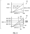
- FIG. 3 illustrates graphs that represent operational features of the hydraulic control system 24 of FIG. 2 , in accordance with an embodiment of the present disclosure.
- a first graph 100 illustrates a joystick position percentage along an x-axis and a hydraulic fluid flow percentage along a y-axis.
- a second graph 102 illustrates a joystick position percentage along an x-axis and a speed percentage along a y-axis.
- the hydraulic control system may operate the hydraulic system with two speed ranges (e.g., Speed Range 2, indicated by line 104; Speed Range 4, indicated by line 106).
- Speed Range 2 a motor volume of the hydraulic motor may be set to a first motor volume, and a pump displacement limit for the hydraulic pump may be set to a first limit (e.g., 100 percent).
- Speed Range 4 the motor volume of the hydraulic motor may be set to a second motor volume (e.g., different than the first motor volume; less than the first motor volume, such as 50 percent of the first motor volume), and the pump displacement limit for the hydraulic pump may be set (e.g., maintained) at the first limit.
- the Speed Range 2 and the Speed Range 4 may represent first settings (e.g., default settings; two-speed operation) that may be used while the virtual gears and their corresponding speed ranges are inactive (e.g., not selected or enabled).
- the hydraulic control system 24 may operate the hydraulic system with additional speed ranges, such as four speed ranges (e.g., Speed Range 1, indicated by line 108; Speed Range 2, indicated by line 104; Speed Range 3, indicated by line 110; Speed Range 4, indicated by line 106).
- Speed Range 1 the motor volume of the hydraulic motor may be set to the first motor volume, and the pump displacement limit may be set to a second limit (e.g., less than the first limit, such as 50 percent of the first limit).
- the motor volume of the hydraulic motor may be set to the second motor volume, and the pump displacement limit may be set to the second limit.
- the Speed Range 1 and the Speed Range 3 may represent speed ranges achieved via virtual gears (e.g., by activation, selection, or enablement of the virtual gears).
- the hydraulic system may include a two-speed hydraulic motor (e.g., adjustable between the first motor volume and the second motor volume to provide the Speed Range 2 and the Speed Range 4), and the hydraulic control system may coordinate control of the two-speed hydraulic motor and the hydraulic pump (e.g., adjustable between the first displacement limit and the second pump displacement limit to provide the Speed Range 1 and the Speed Range 3) to provide additional speed ranges (e.g., Speed Range 1, Speed Range 2, Speed Range 3, Speed Range 4, or any combination thereof).
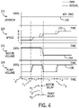
- FIG. 4 illustrates graphs that represent operational features of the hydraulic control system 24 of FIG. 2 over time, in accordance with an embodiment of the present disclosure.
- the graphs illustrate different inputs or responses with respect to time, which is shown along an x-axis.
- a first graph 122 illustrates an input command (e.g., joystick command; a joystick position percentage) along a y-axis relative to the time along the x-axis.
- a second graph 124 illustrates a change in speed of the work vehicle along a y-axis relative to the time along the x-axis.
- the third graph 126 illustrates a change in a motor volume of the hydraulic motor along a y-axis relative to the time along the x-axis.
- a fourth graph 128 illustrates a change in a pump volume of the hydraulic pump (which affects the flow rate of the hydraulic fluid to the hydraulic motor and is limited by the pump displacement limit) along a y-axis relative to the time along the x-axis.
- certain commanded actions e.g., motor volume command to adjust the motor volume; pump action command to adjust the pump volume
- dashed lines that extend along the x-axis
- actual changes e.g., in speed, volume
- these graphs 122, 124, 126, 128 include various lines that illustrate the input command into the hydraulic system via the one or more input devices, responses of the hydraulic system to commands that change motor volume and/or pump volume, as well as how the changes in the motor volume and/or the pump volume affect the speed of the work vehicle.
- the hydraulic system has been set to have four speed ranges (e.g., illustrated as 1, 2, 3, and 4 in the graph 124; corresponding to FIG. 3 ), although the hydraulic system may be set to have more or less speed ranges.
- the operator may set the hydraulic system to have the four speed ranges prior to the work operation, such as upon powering on the work vehicle or at any other time.
- the operator may provide a shift command to shift to select one of the speed ranges of the four speed ranges. Then, during the work operation, the operator may provide the input command to adjust the speed within the selected speed range (e.g., current speed range or gear).
- the selected speed range e.g., current speed range or gear
- the first graph 122 includes a line 130 that illustrates the input command (e.g., provided based on the joystick position percentage) to control the speed of the work vehicle within the selected speed range.
- the hydraulic control system e.g., the controller
- the input command is shown at a maximum (e.g., 100 percent of the joystick position; at a maximum position of the joystick) for the purposes of discussion, the speed of the work vehicle is shown to adjust to a maximum speed within the selected speed range.
- the third graph 126 includes a line 134 that illustrates the motor volume of the hydraulic motor.
- the motor volume may be a first motor volume (e.g., 100 percent) or a second motor volume (e.g., less than the first motor volume, such as 50 percent of the first motor volume).
- the fourth graph 128 includes a line 136 that illustrates the pump volume of the hydraulic pump.
- the pump volume may be limited by a first limit (e.g., 100 percent) or by a second limit (e.g., less than the first limit, such as 50 percent of the first limit). It should be appreciated that additional limits (e.g., 25 percent, 75 percent) may be provided to increase the number of gears and their corresponding speed ranges for the work vehicle.
- the limit may be described herein as limiting pump displacement and/or limiting pump volume and/or limiting the flow rate of hydraulic fluid, as the result of each is the limiting of the flow rate of hydraulic fluid.
- the input command is at the maximum in this example, and thus, the pump volume is shown to adjust to the first limit and to the second limit.
- the pump volume may vary up to the respective limit for the selected speed range and based on the input command.
- the hydraulic control system may adjust the motor volume and the limit for the pump volume to provide the four different speed ranges for the work vehicle.
- the operator may select a first gear (e.g., virtual gear) that corresponds to a first speed range (e.g., lowest speed range). Then, during a first time period, t 1 , the motor volume may be the first motor volume (e.g., 100 percent) and the pump volume may be set to have the second limit (e.g., 50 percent) to thereby make the first speed range available to the work vehicle. Then, when the operator moves the input device to the maximum (e.g., maximum position of the joystick), the speed of the work vehicle may be at the respective maximum speed of the first speed range.
- a first gear e.g., virtual gear
- the motor volume may be the first motor volume (e.g., 100 percent) and the pump volume may be set to have the second limit (e.g., 50 percent) to thereby make the first speed range available to the work vehicle.
- the maximum e.g., maximum position of the joystick
- the operator may provide an input to shift to a second gear (e.g., a mechanical gear; remove the overlaid virtual gear) that corresponds to a second speed range.
- a second gear e.g., a mechanical gear; remove the overlaid virtual gear
- the motor volume may be maintained at the first motor volume (e.g., 100 percent) and the pump volume may be set to have the first limit (e.g., 100 percent) to thereby make the second speed range available for the work vehicle.
- the speed of the work vehicle may move to and be held at the respective maximum speed of the second speed range.
- the pump volume may increase over time until the first limit on the pump volume is reached, which results in the speed of the work vehicle increasing over time to the maximum speed of the second speed range. This may provide for a smooth transition between speeds as the operator shifts the gears (including the virtual gears) for the work vehicle.
- the operator may provide an input to shift to a third gear (e.g., a virtual gear) that corresponds to a third speed range.
- a third gear e.g., a virtual gear
- the motor volume may be decreased to the second motor volume (e.g., 50 percent) and the pump volume may be decreased to fall within the second limit for the pump volume (e.g., 50 percent) to thereby make the third speed range available for the work vehicle.
- the speed of the work vehicle may move to and be held at the respective maximum speed of the third speed range.
- the motor volume and the pump volume may decrease over time, which results in the speed of the work vehicle increasing over time to the maximum speed of the third speed range.
- the respective motor command to decrease the motor volume may be provided after a first delay period, d 1 , (e.g., motor delay period), and the respective pump command to decrease the pump volume may be provided after a second delay period, d 2 , (e.g., pump delay period).
- d 1 e.g., motor delay period
- d 2 e.g., pump delay period
- the first delay period, d 1 , and the second delay period, d 2 may be the same (e.g., zero difference).
- the first delay period, d 1 , and the second delay period, d 2 may be different from one another, such as to account for whether the hydraulic motor or the hydraulic pump takes longer to respond to their respective command.
- the first delay period, d 1 , and the second delay period, d 2 may be selected to provide for simultaneous (e.g., essentially simultaneous and/or overlapping in time) changes in the motor volume and the pump volume, which may provide for a smoother transition between speeds as the operator shifts the gears (including the virtual gears) for the work vehicle.
- the operator may provide an input to shift to a fourth gear (e.g., a mechanical gear; remove the overlaid virtual gear) that corresponds to a fourth speed range.
- a fourth gear e.g., a mechanical gear; remove the overlaid virtual gear
- the motor volume may be maintained at the second motor volume (e.g., 50 percent) and the pump volume may be increased up to the first limit (e.g., 100 percent) to thereby make the fourth speed range available for the work vehicle.
- the second motor volume e.g., 50 percent
- the pump volume may be increased up to the first limit (e.g., 100 percent) to thereby make the fourth speed range available for the work vehicle.
- the speed of the work vehicle may move to and be held at the respective maximum speed of the fourth speed range.
- the pump volume may increase over time up to the first limit for the pump volume, which results in the speed of the work vehicle increasing over time to the maximum speed of the fourth speed range. This may provide for a smooth transition between speeds as the operator shifts the gears (including the virtual gears) for the work vehicle.
- the hydraulic control system in response to the input to shift the speed range for the work vehicle, the hydraulic control system generates the motor command and/or the pump command. These commands are sent to the hydraulic motor(s) and hydraulic pump(s), respectively, and change the volume of the hydraulic motor(s) and the limit for the volume of hydraulic fluid pumped by the hydraulic pump(s), respectively. As discussed above and as illustrated, these changes may be rapid changes, but are not instantaneous jumps. For example, there may be a rapid linear change (e.g., with a non-zero slope) between the first motor volume and the second motor volume.
- speed ranges While four speed ranges are illustrated, it should be appreciated that additional speed ranges may be added or one or more of the four speed ranges may be omitted (e.g., based on the input by the operator). That is, the operator may use any one, two, or three of the four speed ranges shown in FIG. 4 and/or the operator may add other speed ranges other than the four speed ranges shown in FIG. 4 .
- FIGS. 5 and 6 illustrate examples of graphical user interfaces that may be utilized to facilitate configuration of the hydraulic system by the operator.
- a graphical user interface 140 may be provided via a display screen 142, which may be within the cab of the work vehicle.
- the graphical user interface 140 may be provided to the operator in response to a request by the operator and/or at any other time (e.g., automatically each time the work vehicle is powered on).
- the graphical user interface 140 may provide a list of available transmission modes, such as a two-speed mode, a three-speed mode, or a four-speed mode. These may be saved modes with corresponding speed ranges (e.g., in the memory of the hydraulic control system; set at manufacturing and/or previously set by the operator).
- the display screen 142 may be a touchscreen that is configured to receive inputs from the operator, and in such cases, the operator may select a particular transmission mode by touching the display screen 142.
- the input may be provided in any of a variety of other ways, such as by using auxiliary devices (e.g., a keyboard and/or a push button/dial) to move through the available transmission modes and to select one of the available transmission modes.
- auxiliary devices e.g., a keyboard and/or a push button/dial
- the graphical user interface 140 may also include selectable icons and/or may operate as a menu to thereby enable the operator to select one of the transmission modes to view additional information (e.g., the speed ranges, including a maximum speed of each of the speed ranges) and/or to adjust characteristics of the transmission modes (e.g., to adjust the speed ranges, including the maximum speed of each of the speed ranges). It should be appreciated that additional information, such as the speed set points) may be provided as part of the list of available transmission modes in the graphical user interface 140 as well.
- additional information such as the speed set points
- a graphical user interface 150 may be provided via the display screen 142.
- the graphical user interface 150 may be provided to the operator in response to a request by the operator and/or at any other time (e.g., automatically each time the work vehicle is powered on; after selection of the transmission mode and/or the number of speed ranges).
- the graphical user interface 150 may provide a list or a table of gears, as well as associated speed ranges (e.g., the maximum speed) for each of the gears.
- the display screen 142 may be a touchscreen that is configured to receive inputs from the operator, and in such cases, the operator may select icons (e.g., up arrows, down arrows, numbers) presented on the display screen 150.
- icons e.g., up arrows, down arrows, numbers
- the input may be provided in any of a variety of other ways, such as by using auxiliary devices (e.g., a keyboard and/or a push button/dial) to type and/or enter the speed ranges.
- the graphical user interface 150 may provide a selectable icon to facilitate saving the speed ranges for future use (e.g., to be presented in a list of available transmission modes, such as in the list of FIG. 5 , at a later time).
- the operator may save a first configuration with three gears that correspond to three speed set points (e.g., 4 miles per hour (MPH), 8 MPH, and 12 MPH) as “Basement Dig,” and the operator may save a second configuration with two gears that correspond to two speed set points (e.g., 6 MPH and 12 MPH) as "Long Haul.”
- these configurations may be provided in the list of available transmission modes, such as by providing their operator-provided names (e.g., "Basement Dig") and/or the characteristics (e.g., the number of gears and the speed set points).
- the hydraulic system may enable the operator to select the number of gears and speed ranges via a switch (e.g., a 2-way, 3-way, 4-way switch; rotary switch or dial) that is switchable between discrete positions that correspond to a respective number of gears and speed ranges.
- the switch may be physical components that are provided within the cab of the work vehicle, although the switch may instead be virtual components that are displayed on the display screen 142.
- the operator may configure the hydraulic system as desired for certain operations.
- the two-speed transmission mode may be desirable for certain operations where fine speed control is not needed and where the operator prefers to limit shifting.
- a three-speed transmission mode, a four-speed transmission mode, or other transmission modes may be desirable for certain operations where fine speed control is beneficial and where the operator is willing to carry out multiple shifts in order to achieve the fine speed control.
- two-speed, three-speed, and four-speed operations are illustrated and described in detail, it should be appreciated that the disclosed embodiments may be adapted for five-speed operations, six-speed operations, or more.
- additional motor volumes and/or pump volumes may be provided.
- the disclosed techniques may be adapted for use with a hydraulic transmission and a variable motor.
- the motor volume and the pump volume would be remapped in response to each re-configuration of the hydraulic system.
- the disclosed techniques may be adapted for use with a hydraulic transmission and a fixed displacement motor (e.g., no command is provided to the motor). In such cases, the pump volume would be changed to provide different speed ranges.
- the disclosed techniques may be adapted for use with any hydraulic, electric, or mechanical transmission.
- a hydraulic control system that provides a variable, configurable number of speed ranges for a work vehicle.
- the operator may use full motion of the input device (e.g., joystick, between its minimum and maximum positions) within each gear and speed range of the selected number of speed ranges for the work vehicle.
- the minimum and maximum speed available to the work vehicle may remain the same regardless of the selected number of gears and speed ranges for the work vehicle.
- changing the number of gears and speed ranges does not involve increasing or decreasing the speed available to the work vehicle (e.g., decreasing the number of gears and speed ranges does not involve removing the highest gear and the highest speed range, but instead provides fewer gears between the lowest gear and the highest gear and fewer speed ranges between the lowest speed range and the highest speed range; the hydraulic system does not create four gears and speed ranges and then operate by excluding some of the four gears and speed ranges).
- changing the number of gears and speed ranges increases or decreases a number of shifts that are used to move from the minimum and maximum speed for the work vehicle.
Landscapes
- Engineering & Computer Science (AREA)
- General Engineering & Computer Science (AREA)
- Mining & Mineral Resources (AREA)
- Civil Engineering (AREA)
- Structural Engineering (AREA)
- Mechanical Engineering (AREA)
- Physics & Mathematics (AREA)
- Fluid Mechanics (AREA)
- Control Of Fluid Gearings (AREA)
Abstract
Description
- A hydraulic system may include a hydraulic pump that pressurizes a hydraulic fluid to generate a pressurized hydraulic fluid, which may then be used to perform various tasks. A work vehicle (e.g., an agricultural vehicle and/or a construction vehicle, such as a skid steer) may include the hydraulic system. In such cases, the pressurized hydraulic fluid may be used to actuate a hydraulic motor that generates rotational power to drive one or more wheels of the work vehicle.
- In one embodiment, a hydraulic system for a work vehicle includes a hydraulic motor configured to generate rotational power for one or more wheels on the work vehicle. The hydraulic system also includes a hydraulic pump coupled to the hydraulic motor, wherein the hydraulic pump is configured to pump hydraulic fluid to the hydraulic motor. The hydraulic control system includes a processor that is configured to receive an input indicative of a selection of a number of speed ranges that span between a minimum speed and a maximum speed for the work vehicle and to provide a motor command to set a motor volume of the hydraulic motor and a pump command to set a limit for a pump volume of the hydraulic pump to enable the number of speed ranges for the work vehicle.
- In one embodiment, a hydraulic control system for a work vehicle includes a processor that is configured to receive a configuration input from an operator indicative of a selection of a first number of speed ranges that span between a minimum speed and a maximum speed for the work vehicle. The processor is also configured to receive a first shift input from the operator indicative of a request to shift to a first speed range of the first number of speed ranges. The processor is further configured to provide a pump command to set a limit for a pump volume to a first limit to enable the first speed range of the first number of speed ranges.
- In one embodiment, a method of operating a hydraulic system for a work vehicle includes receiving, at one or more processors, an input indicative of a selection of a first number of speed ranges that span between a minimum speed and a maximum speed for the work vehicle. The method includes adjusting, using the one or more processors, a motor volume of a hydraulic motor, a limit for a pump volume of a hydraulic pump, or both to enable the number of speed ranges. The method also includes receiving, at the one or more processors, an additional input indicative of an additional selection of a second number of speed ranges that span between the minimum speed and the maximum speed for the work vehicle. The method further includes adjusting, using the one or more processors, the motor volume of the hydraulic motor and the limit for the pump volume of the hydraulic pump to enable the second number of speed ranges.
- These and other features, aspects, and advantages of the present disclosure will become better understood when the following detailed description is read with reference to the accompanying drawings in which like characters represent like parts throughout the drawings, wherein:
-
FIG. 1 is a side view of a work vehicle, in accordance with an embodiment of the present disclosure; -
FIG. 2 is a schematic diagram of a hydraulic system that may be used in the work vehicle ofFIG. 1 , in accordance with an embodiment of the present disclosure; -
FIG. 3 illustrates graphs that represent operational features of the hydraulic system ofFIG. 2 , in accordance with an embodiment of the present disclosure; -
FIG. 4 illustrates graphs that represent operational features of the hydraulic system ofFIG. 2 over time, in accordance with an embodiment of the present disclosure; -
FIG. 5 illustrates a graphical user interface that may be presented to facilitate user selection of a number of gears and corresponding speed ranges for the hydraulic system ofFIG. 2 , in accordance with an embodiment of the present disclosure; and -
FIG. 6 illustrates a graphical user interface that may be presented to facilitate user input to configure the hydraulic system ofFIG. 2 , in accordance with an embodiment of the present disclosure. - Work vehicles (e.g., agricultural vehicles; construction vehicles, such as a skid steer) may include one or more hydraulic systems that provide power to complete various tasks. These various tasks may include loading, lifting, pushing, rotating, dozing, and/or moving the work vehicle. For example, a work vehicle may include a hydraulic system that includes one or more hydraulic motors that drive wheels of the work vehicle. The wheels in turn couple to tracks, which enable the work vehicle to traverse various types of terrain. An operator may want to adjust a speed range for the work vehicle depending on the task and/or the terrain. To change the speed range for the work vehicle (e.g., between a first speed range, such as a lower speed range, and a second speed range, such as a higher speed range), the operator may provide a shifting command via one or more input devices (e.g., a switch). The shifting command may cause the hydraulic system to increase or to decrease a hydraulic motor volume of the one or more hydraulic motors.
- As an example, in some work vehicles with two-speed hydraulic motors, the shifting command may cause the hydraulic system to adjust each of the hydraulic motors from a first motor volume (e.g., a higher volume; for the first, lower speed range) to a second motor volume (e.g., a lower volume; for the second, higher speed range). The operator may provide a drive command via one or more input devices (e.g., a joystick) to adjust a flow rate of hydraulic fluid from one or more hydraulic pumps to the one or more hydraulic motors that have the second motor volume. When the flow rate of hydraulic fluid is unchanged (e.g., is at a particular flow rate for a given position of the one or more input devices), the change to the motor volume from the first motor volume to the second motor volume causes the motor speed to increase to allow the hydraulic fluid (e.g., at the particular flow rate) to pass through the second motor volume.
- It is presently recognized that it would be desirable to make additional speed ranges for the work vehicle (e.g., for the work vehicle having two-speed hydraulic motors) available to the operator. Furthermore, it is presently recognized that it would be desirable to make the additional speed ranges adjustable (e.g., selectable, configurable) by the operator and/or to limit physical, mechanical changes to the work vehicle (e.g., to implement the additional speed ranges using existing components, such as the hydraulic motors and the hydraulic pumps; to implement the additional speed ranges via virtual gears that are established using a controller carrying out a software program stored in a memory).
- Accordingly, the present disclosure relates generally to a hydraulic system (e.g., configurable hydraulic system) that includes configurable virtual gears (e.g., pseudo gears; gear ratios) to enable the operator to establish any number of speed ranges (e.g., 1, 2, 3, 4, 5, 6 or more) for the work vehicle. For example, the operator may select (e.g., via a graphical user interface displayed in the work vehicle) a number of virtual gears that are overlaid onto (e.g., used together with) mechanical gears (e.g., hydro-mechanical gears; gear ratios) to provide a total number of gears and corresponding speed ranges for the work vehicle. As a more specific example, the operator may select two virtual gears that are overlaid onto two mechanical gears (e.g., the two mechanical gears that would provide two speed ranges without the virtual gears) to provide a total of four gears and four speed ranges for the work vehicle. It should be appreciated that each of the gears corresponds to a respective speed range for the work vehicle, and thus, the terms "gears" and "speed ranges" may be used to describe operational features of the hydraulic system. A minimum speed and a maximum speed for the work vehicle may be unchanged by the addition of the virtual gears. Instead, the number of speed ranges provided between (e.g., that span between to include) the minimum speed and the maximum speed may vary to provide varying levels of control (e.g., finer control options with a higher number of speed ranges, as opposed to only coarser control options with a lower number of speed ranges) using the one or more input devices (e.g., the joystick).
-
FIG. 1 is a side view of an embodiment of a work vehicle 10 (e.g., a skid steer). Thework vehicle 10 may includewheels 11 andtracks 12 that enable thework vehicle 10 to move. Thework vehicle 10 includes anengine 14 that provides power to ahydraulic system 16. Thehydraulic system 16 in turn provides power to thewheels 11, which then rotate thetracks 12. Thehydraulic system 16 may also provide power to other systems on thework vehicle 10. For example, thehydraulic system 16 may provide power to hydraulic actuators 18 (e.g., hydraulic cylinders) that control operation of one or more arms 20 (e.g., booms). Thearms 20 couple to atool 22 that enable thework vehicle 10 to perform various tasks. For example, thetool 22 may be a fork, bucket, plow, blade, among others. In the illustrated embodiment, thetool 22 is a bucket that enables thework vehicle 10 to perform loading tasks. Thetool 22 may instead be (e.g., changed to) a blade to perform dozing tasks and/or thetool 22 may instead be (e.g., changed to) another type of tool for another type of task. - As discussed in more detail below, the
hydraulic system 16 may include one or more hydraulic pumps and one or more hydraulic motors that provide power to thewheels 11 on thework vehicle 10. In order to enable an operator of thework vehicle 10 to adjust a number of speed ranges available during operation of thework vehicle 10, thework vehicle 10 includes ahydraulic control system 24. As will be explained below, thehydraulic control system 24 controls operation of the one or more hydraulic pumps and the one or more hydraulic motors on thework vehicle 10 based on various inputs from the operator to provide the number of speed ranges selected by the operator. The operator may utilize one or more input devices 26 (e.g., touchscreen display, knobs, switches, joystick) within acab 28 of thework vehicle 10 to provide the various inputs. For example, the operator may utilize one of the input devices 26 (e.g., touchscreen display) to provide the various inputs to set the number of speed ranges. The operator may utilize one of the input devices 26 (e.g., switch) to switch between the speed ranges, and the operator may utilize one of the input devices 26 (e.g., joystick) to adjust a flow rate of hydraulic fluid from the one or more hydraulic pumps to the one or more motors to thereby adjust the speed within a current speed range. -
FIG. 2 is a schematic diagram of an embodiment of thehydraulic system 16 and thehydraulic control system 24 that may be used in a work vehicle, such as in thework vehicle 10 ofFIG. 1 . Thehydraulic system 16 may include a firsthydraulic pump 54 and a secondhydraulic pump 56 that receive hydraulic fluid from a hydraulic accumulator orsource 58. Thefirst pump 54 pressurizes the hydraulic fluid and provides the pressurized hydraulic fluid to the firsthydraulic motor 60. Thesecond pump 56 pressurizes the hydraulic fluid and provides the pressurized hydraulic fluid to a secondhydraulic motor 62. Thehydraulic motors hydraulic motors hydraulic motors second wheels 11. Thewheels 11 in turn may couple to and rotate first andsecond vehicle tracks 12 to drive the work vehicle to move. It should be understood, that thehydraulic system 16 may be modified to include a different number of pumps, hydraulic motors, wheels, and/or tracks (e.g., 1, 2, 3, 4, or more). Furthermore, inFIG. 2 , the hydraulic fluid is shown as returning from thehydraulic motors fluid source 58 to facilitate discussion. However, it should be appreciated that the hydraulic fluid may return directly to thehydraulic pumps - In order to provide enhanced functionality and additional speed ranges, the
hydraulic control system 24 couples to thehydraulic system 16. More specifically, thehydraulic control system 24 couples to and controls operation of the first andsecond pumps hydraulic motors hydraulic control system 24 controls operation of thehydraulic pumps hydraulic motors hydraulic control system 24 may enable the operator to set a first number of speed ranges for a first work operation during a first time period and a second number of speed ranges for a second work operation during a second time period. In other words, thehydraulic control system 24 enables the operator to add virtual gears to mechanical gears via the one ormore input devices 26. - As shown, the
hydraulic control system 24 includes acontroller 72 that receives signals (e.g., command signals) from the one ormore input devices 26. As an example, prior to a first work operation, the operator may utilize the one or more input devices 26 (e.g., the touchscreen display) to select a first number of speed ranges (e.g., to add virtual gears). Then, during the first work operation, the operator may utilize the one or more input devices 26 (e.g., the touchscreen display or a switch) to select a respective first speed range within the first number of speed ranges, and then the operator may utilize the one or more input devices 26 (e.g., the joystick) to drive the work vehicle within the respective first speed range within the first number of speed ranges. At another time during the first work operation, the operator may utilize the one or more input devices 26 (e.g., the touchscreen display or the switch) to select a respective second speed range within the first number of speed ranges (e.g., to shift), and then the operator may utilize the one or more input devices 26 (e.g., the joystick) to drive the work vehicle within the respective second speed range within the first number of speed ranges. - Prior to a second work operation, the operator may utilize the one or more input devices 26 (e.g., the touchscreen display) to select a second number of speed ranges (e.g., to remove the virtual gears). Then, during the second work operation, the operator may utilize the one or more input devices 26 (e.g., the touchscreen display or the switch) to select a respective first speed range within the second number of speed ranges, and then the operator may utilize the one or more input devices 26 (e.g., the joystick) to drive the work vehicle within the respective first speed range of the second number of speed ranges. At another time during the second work operation, the operator may utilize the one or more input devices 26 (e.g., the touchscreen display or the switch) to select a respective second speed range within the second number of speed ranges (e.g., to shift), and then the operator may utilize the one or more input devices 26 (e.g., the joystick) to drive the work vehicle within the respective second speed range within the second number of speed ranges, and so on. In this way, the operator may select/adjust the number of speed ranges (e.g., at the beginning of a work operation) and may also select/shift between speed ranges of the number of speed ranges (e.g., during the work operation).
- In this example, the first number of speed ranges (e.g., with the virtual gears) may be greater than the second number of speed ranges (e.g., without the virtual gears). Furthermore, the respective first speed range within the first number of speed ranges may include different speeds than the respective first speed range within the second number of speed ranges. This is because the minimum speed and the maximum speed for the work vehicle may remain unchanged; however, the number of speed ranges available between the minimum speed and the maximum speed for the work vehicle may vary, thereby resulting in at least some differences in the speeds available within at least some of the ranges (e.g., a respective lowest speed range within a higher number of speed ranges may be narrower than a respective lowest speed range within a lower number of speed ranges).
- As discussed in more detail below, the
controller 72 receives and processes signals (e.g., shift commands) from the one ormore input devices 26 and executes instructions stored on amemory 78 to control operation of thepumps 54, 56 (e.g., via pump commands) and thehydraulic motors 60, 62 (e.g., via motor commands) to drive the work vehicle in this way. Theprocessor 76 may be a microprocessor that executes software that enables control of thehydraulic system 16. Theprocessor 76 may include multiple microprocessors, one or more "general-purpose" microprocessors, one or more special-purpose microprocessors, and/or one or more application specific integrated circuits (ASICs), field-programmable gate arrays (FPGAs), or some combination thereof. For example, theprocessor 76 may include one or more reduced instruction set computer (RISC) processors. Thememory 78 may include a volatile memory, such as random access memory (RAM), and/or a nonvolatile memory, such as read-only memory (ROM). Thememory 78 may store a variety of information and may be used for various purposes. For example, thememory 78 may store processor executable instructions, such as firmware or software, for theprocessor 76 to execute. Thememory 78 may include ROM, flash memory, a hard drive, or any other suitable optical, magnetic, or solid-state storage medium or a combination thereof. Thememory 78 may store data, instructions, and any other suitable data. -
FIG. 3 illustrates graphs that represent operational features of thehydraulic control system 24 ofFIG. 2 , in accordance with an embodiment of the present disclosure. Afirst graph 100 illustrates a joystick position percentage along an x-axis and a hydraulic fluid flow percentage along a y-axis. Asecond graph 102 illustrates a joystick position percentage along an x-axis and a speed percentage along a y-axis. - During some operations (e.g., a first work operation), the hydraulic control system may operate the hydraulic system with two speed ranges (e.g.,
Speed Range 2, indicated byline 104;Speed Range 4, indicated by line 106). AtSpeed Range 2, a motor volume of the hydraulic motor may be set to a first motor volume, and a pump displacement limit for the hydraulic pump may be set to a first limit (e.g., 100 percent). AtSpeed Range 4, the motor volume of the hydraulic motor may be set to a second motor volume (e.g., different than the first motor volume; less than the first motor volume, such as 50 percent of the first motor volume), and the pump displacement limit for the hydraulic pump may be set (e.g., maintained) at the first limit. In the illustratedgraphs Speed Range 2 and theSpeed Range 4 may represent first settings (e.g., default settings; two-speed operation) that may be used while the virtual gears and their corresponding speed ranges are inactive (e.g., not selected or enabled). - During other operations (e.g., a second work operation), the
hydraulic control system 24 may operate the hydraulic system with additional speed ranges, such as four speed ranges (e.g.,Speed Range 1, indicated byline 108;Speed Range 2, indicated byline 104;Speed Range 3, indicated byline 110;Speed Range 4, indicated by line 106). AtSpeed Range 1, the motor volume of the hydraulic motor may be set to the first motor volume, and the pump displacement limit may be set to a second limit (e.g., less than the first limit, such as 50 percent of the first limit). AtSpeed Range 3, the motor volume of the hydraulic motor may be set to the second motor volume, and the pump displacement limit may be set to the second limit. - In the illustrated
graphs Speed Range 1 and theSpeed Range 3 may represent speed ranges achieved via virtual gears (e.g., by activation, selection, or enablement of the virtual gears). Thus, in some embodiments, the hydraulic system may include a two-speed hydraulic motor (e.g., adjustable between the first motor volume and the second motor volume to provide theSpeed Range 2 and the Speed Range 4), and the hydraulic control system may coordinate control of the two-speed hydraulic motor and the hydraulic pump (e.g., adjustable between the first displacement limit and the second pump displacement limit to provide theSpeed Range 1 and the Speed Range 3) to provide additional speed ranges (e.g.,Speed Range 1,Speed Range 2,Speed Range 3,Speed Range 4, or any combination thereof). -
FIG. 4 illustrates graphs that represent operational features of thehydraulic control system 24 ofFIG. 2 over time, in accordance with an embodiment of the present disclosure. The graphs illustrate different inputs or responses with respect to time, which is shown along an x-axis. In particular, afirst graph 122 illustrates an input command (e.g., joystick command; a joystick position percentage) along a y-axis relative to the time along the x-axis. Asecond graph 124 illustrates a change in speed of the work vehicle along a y-axis relative to the time along the x-axis. Thethird graph 126 illustrates a change in a motor volume of the hydraulic motor along a y-axis relative to the time along the x-axis. Afourth graph 128 illustrates a change in a pump volume of the hydraulic pump (which affects the flow rate of the hydraulic fluid to the hydraulic motor and is limited by the pump displacement limit) along a y-axis relative to the time along the x-axis. In thegraphs graphs - As noted above, these
graphs graph 124; corresponding toFIG. 3 ), although the hydraulic system may be set to have more or less speed ranges. As discussed herein, the operator may set the hydraulic system to have the four speed ranges prior to the work operation, such as upon powering on the work vehicle or at any other time. Then, during the work operation, the operator may provide a shift command to shift to select one of the speed ranges of the four speed ranges. Then, during the work operation, the operator may provide the input command to adjust the speed within the selected speed range (e.g., current speed range or gear). - The
first graph 122 includes aline 130 that illustrates the input command (e.g., provided based on the joystick position percentage) to control the speed of the work vehicle within the selected speed range. The hydraulic control system (e.g., the controller) receives this input command signal and generates a speed command signal to adjust the speed of the work vehicle within the selected speed range (e.g., by increasing the flow of hydraulic fluid, as constrained by the limit on the pump displacement). Because the input command is shown at a maximum (e.g., 100 percent of the joystick position; at a maximum position of the joystick) for the purposes of discussion, the speed of the work vehicle is shown to adjust to a maximum speed within the selected speed range. This is shown in thesecond graph 124, which illustrates aline 132 that represents the change in the speed of the work vehicle. - As mentioned above, the
third graph 126 includes aline 134 that illustrates the motor volume of the hydraulic motor. As shown, the motor volume may be a first motor volume (e.g., 100 percent) or a second motor volume (e.g., less than the first motor volume, such as 50 percent of the first motor volume). Thefourth graph 128 includes aline 136 that illustrates the pump volume of the hydraulic pump. As shown, the pump volume may be limited by a first limit (e.g., 100 percent) or by a second limit (e.g., less than the first limit, such as 50 percent of the first limit). It should be appreciated that additional limits (e.g., 25 percent, 75 percent) may be provided to increase the number of gears and their corresponding speed ranges for the work vehicle. It should be appreciated that the limit may be described herein as limiting pump displacement and/or limiting pump volume and/or limiting the flow rate of hydraulic fluid, as the result of each is the limiting of the flow rate of hydraulic fluid. As noted above, the input command is at the maximum in this example, and thus, the pump volume is shown to adjust to the first limit and to the second limit. However, in operation, the pump volume may vary up to the respective limit for the selected speed range and based on the input command. Generally, the hydraulic control system may adjust the motor volume and the limit for the pump volume to provide the four different speed ranges for the work vehicle. - As an example, at a time point, T0 , the operator may select a first gear (e.g., virtual gear) that corresponds to a first speed range (e.g., lowest speed range). Then, during a first time period, t1 , the motor volume may be the first motor volume (e.g., 100 percent) and the pump volume may be set to have the second limit (e.g., 50 percent) to thereby make the first speed range available to the work vehicle. Then, when the operator moves the input device to the maximum (e.g., maximum position of the joystick), the speed of the work vehicle may be at the respective maximum speed of the first speed range.
- At a time point, T1 , the operator may provide an input to shift to a second gear (e.g., a mechanical gear; remove the overlaid virtual gear) that corresponds to a second speed range. In response to the input to shift to the second gear, during a second time period, t2 , the motor volume may be maintained at the first motor volume (e.g., 100 percent) and the pump volume may be set to have the first limit (e.g., 100 percent) to thereby make the second speed range available for the work vehicle. Then, when the operator moves the input device to the maximum, the speed of the work vehicle may move to and be held at the respective maximum speed of the second speed range. As shown, upon the input to shift to the second gear, the pump volume may increase over time until the first limit on the pump volume is reached, which results in the speed of the work vehicle increasing over time to the maximum speed of the second speed range. This may provide for a smooth transition between speeds as the operator shifts the gears (including the virtual gears) for the work vehicle.
- At a time point, T2 , the operator may provide an input to shift to a third gear (e.g., a virtual gear) that corresponds to a third speed range. In response to the input to the shift to the third gear, during a third time period, t3 , the motor volume may be decreased to the second motor volume (e.g., 50 percent) and the pump volume may be decreased to fall within the second limit for the pump volume (e.g., 50 percent) to thereby make the third speed range available for the work vehicle. Then, when the operator moves the input device to the maximum, the speed of the work vehicle may move to and be held at the respective maximum speed of the third speed range. As shown, upon the input to shift to the third gear, the motor volume and the pump volume may decrease over time, which results in the speed of the work vehicle increasing over time to the maximum speed of the third speed range.
- In some embodiments, following the shift (e.g., the shift command) at the time point, T2 , there may be a delay prior to a respective motor command to change the motor volume and/or prior to a respective pump command to change the pump volume. For example, the respective motor command to decrease the motor volume may be provided after a first delay period, d1 , (e.g., motor delay period), and the respective pump command to decrease the pump volume may be provided after a second delay period, d2 , (e.g., pump delay period). In some embodiments, the first delay period, d1 , and the second delay period, d2 , may be the same (e.g., zero difference). In some embodiments, the first delay period, d1 , and the second delay period, d2 , may be different from one another, such as to account for whether the hydraulic motor or the hydraulic pump takes longer to respond to their respective command. The first delay period, d1 , and the second delay period, d2 , may be selected to provide for simultaneous (e.g., essentially simultaneous and/or overlapping in time) changes in the motor volume and the pump volume, which may provide for a smoother transition between speeds as the operator shifts the gears (including the virtual gears) for the work vehicle.
- At a time point, T3 , the operator may provide an input to shift to a fourth gear (e.g., a mechanical gear; remove the overlaid virtual gear) that corresponds to a fourth speed range. In response to the input to the shift to the fourth gear, during a fourth time period, t4 , the motor volume may be maintained at the second motor volume (e.g., 50 percent) and the pump volume may be increased up to the first limit (e.g., 100 percent) to thereby make the fourth speed range available for the work vehicle. Then, when the operator moves the input device to the maximum, the speed of the work vehicle may move to and be held at the respective maximum speed of the fourth speed range. As shown, upon the input to shift to the fourth gear, the pump volume may increase over time up to the first limit for the pump volume, which results in the speed of the work vehicle increasing over time to the maximum speed of the fourth speed range. This may provide for a smooth transition between speeds as the operator shifts the gears (including the virtual gears) for the work vehicle.
- It should be appreciated that in response to the input to shift the speed range for the work vehicle, the hydraulic control system generates the motor command and/or the pump command. These commands are sent to the hydraulic motor(s) and hydraulic pump(s), respectively, and change the volume of the hydraulic motor(s) and the limit for the volume of hydraulic fluid pumped by the hydraulic pump(s), respectively. As discussed above and as illustrated, these changes may be rapid changes, but are not instantaneous jumps. For example, there may be a rapid linear change (e.g., with a non-zero slope) between the first motor volume and the second motor volume. While four speed ranges are illustrated, it should be appreciated that additional speed ranges may be added or one or more of the four speed ranges may be omitted (e.g., based on the input by the operator). That is, the operator may use any one, two, or three of the four speed ranges shown in
FIG. 4 and/or the operator may add other speed ranges other than the four speed ranges shown inFIG. 4 . -
FIGS. 5 and 6 illustrate examples of graphical user interfaces that may be utilized to facilitate configuration of the hydraulic system by the operator. For example, as shown inFIG. 5 , agraphical user interface 140 may be provided via adisplay screen 142, which may be within the cab of the work vehicle. Thegraphical user interface 140 may be provided to the operator in response to a request by the operator and/or at any other time (e.g., automatically each time the work vehicle is powered on). Thegraphical user interface 140 may provide a list of available transmission modes, such as a two-speed mode, a three-speed mode, or a four-speed mode. These may be saved modes with corresponding speed ranges (e.g., in the memory of the hydraulic control system; set at manufacturing and/or previously set by the operator). - The
display screen 142 may be a touchscreen that is configured to receive inputs from the operator, and in such cases, the operator may select a particular transmission mode by touching thedisplay screen 142. However, it should be appreciated that the input may be provided in any of a variety of other ways, such as by using auxiliary devices (e.g., a keyboard and/or a push button/dial) to move through the available transmission modes and to select one of the available transmission modes. Thegraphical user interface 140 may also include selectable icons and/or may operate as a menu to thereby enable the operator to select one of the transmission modes to view additional information (e.g., the speed ranges, including a maximum speed of each of the speed ranges) and/or to adjust characteristics of the transmission modes (e.g., to adjust the speed ranges, including the maximum speed of each of the speed ranges). It should be appreciated that additional information, such as the speed set points) may be provided as part of the list of available transmission modes in thegraphical user interface 140 as well. - As shown in
FIG. 6 , agraphical user interface 150 may be provided via thedisplay screen 142. Thegraphical user interface 150 may be provided to the operator in response to a request by the operator and/or at any other time (e.g., automatically each time the work vehicle is powered on; after selection of the transmission mode and/or the number of speed ranges). Thegraphical user interface 150 may provide a list or a table of gears, as well as associated speed ranges (e.g., the maximum speed) for each of the gears. - As noted above, the
display screen 142 may be a touchscreen that is configured to receive inputs from the operator, and in such cases, the operator may select icons (e.g., up arrows, down arrows, numbers) presented on thedisplay screen 150. However, it should be appreciated that the input may be provided in any of a variety of other ways, such as by using auxiliary devices (e.g., a keyboard and/or a push button/dial) to type and/or enter the speed ranges. Thegraphical user interface 150 may provide a selectable icon to facilitate saving the speed ranges for future use (e.g., to be presented in a list of available transmission modes, such as in the list ofFIG. 5 , at a later time). For example, the operator may save a first configuration with three gears that correspond to three speed set points (e.g., 4 miles per hour (MPH), 8 MPH, and 12 MPH) as "Basement Dig," and the operator may save a second configuration with two gears that correspond to two speed set points (e.g., 6 MPH and 12 MPH) as "Long Haul." Then, these configurations may be provided in the list of available transmission modes, such as by providing their operator-provided names (e.g., "Basement Dig") and/or the characteristics (e.g., the number of gears and the speed set points). - It should be appreciated that other information may be displayed to the operator, such as on the
display screen 142. During operation, the current gear and/or the current speed range, as well the available gears and/or the available speed ranges, may be displayed to the operator on thedisplay screen 142. Furthermore, the hydraulic system may enable the operator to select the number of gears and speed ranges via a switch (e.g., a 2-way, 3-way, 4-way switch; rotary switch or dial) that is switchable between discrete positions that correspond to a respective number of gears and speed ranges. The switch may be physical components that are provided within the cab of the work vehicle, although the switch may instead be virtual components that are displayed on thedisplay screen 142. - In this way, the operator may configure the hydraulic system as desired for certain operations. For example, the two-speed transmission mode may be desirable for certain operations where fine speed control is not needed and where the operator prefers to limit shifting. However, a three-speed transmission mode, a four-speed transmission mode, or other transmission modes may be desirable for certain operations where fine speed control is beneficial and where the operator is willing to carry out multiple shifts in order to achieve the fine speed control. While two-speed, three-speed, and four-speed operations are illustrated and described in detail, it should be appreciated that the disclosed embodiments may be adapted for five-speed operations, six-speed operations, or more. For example, additional motor volumes and/or pump volumes may be provided. Furthermore, the disclosed techniques may be adapted for use with a hydraulic transmission and a variable motor. In such cases, the motor volume and the pump volume would be remapped in response to each re-configuration of the hydraulic system. Furthermore, the disclosed techniques may be adapted for use with a hydraulic transmission and a fixed displacement motor (e.g., no command is provided to the motor). In such cases, the pump volume would be changed to provide different speed ranges. Indeed, the disclosed techniques may be adapted for use with any hydraulic, electric, or mechanical transmission.
- Technical effects of the disclosure include a hydraulic control system that provides a variable, configurable number of speed ranges for a work vehicle. The operator may use full motion of the input device (e.g., joystick, between its minimum and maximum positions) within each gear and speed range of the selected number of speed ranges for the work vehicle. The minimum and maximum speed available to the work vehicle may remain the same regardless of the selected number of gears and speed ranges for the work vehicle. For example, changing the number of gears and speed ranges does not involve increasing or decreasing the speed available to the work vehicle (e.g., decreasing the number of gears and speed ranges does not involve removing the highest gear and the highest speed range, but instead provides fewer gears between the lowest gear and the highest gear and fewer speed ranges between the lowest speed range and the highest speed range; the hydraulic system does not create four gears and speed ranges and then operate by excluding some of the four gears and speed ranges). Instead, changing the number of gears and speed ranges increases or decreases a number of shifts that are used to move from the minimum and maximum speed for the work vehicle.
Claims (15)
- A hydraulic system (16) for a work vehicle (10), the hydraulic system (16) comprising:a hydraulic motor (60, 62) configured to generate rotational power for one or more wheels (11) on the work vehicle (10);a hydraulic pump (54, 56) coupled to the hydraulic motor (60, 62), wherein the hydraulic pump (54, 56) is configured to pump hydraulic fluid to the hydraulic motor (60, 62); anda hydraulic control system (24) comprising a processor (76) that is configured to:receive an input indicative of a selection of a number of speed ranges that span between a minimum speed and a maximum speed for the work vehicle (10); andprovide a motor command to set a motor volume of the hydraulic motor (60, 62) and a pump command to set a limit for a pump volume of the hydraulic pump (54, 56) to enable the number of speed ranges for the work vehicle (10).
- The hydraulic system (16) of claim 1, wherein the hydraulic motor (60, 62) is a two-speed motor and the number of speed ranges is four speed ranges.
- The hydraulic system (16) of claims 1 and 2, wherein the processor (76) is configured to set the motor volume at a first motor volume and to adjust the limit for the pump volume between a first pump volume and a second pump volume while the motor volume is at the first motor volume to enable two lower speed ranges of the four speed ranges while the motor volume is at the first motor volume.
- The hydraulic system (16) of claim 3, wherein the processor (76) is configured to set the motor volume at a second motor volume and to adjust the limit for the pump volume between the first pump volume and the second pump volume while the motor volume is at the second motor volume to enable two higher speed ranges of the four speed ranges while the motor volume is at the second motor volume.
- The hydraulic system (16) of claims 1-4, wherein the processor (76) is configured to receive the input from an operator via one or more input devices (26) within a cab (28) of the work vehicle (10).
- The hydraulic system (16) of claims 5, wherein the one or more input devices (26) comprise a switch that is switchable between discrete positions that each correspond to a different number of speed ranges that span between the minimum speed and the maximum speed for the work vehicle (10).
- The hydraulic system (16) of claims 1-5, wherein the processor (76) is configured to output a graphical user interface (140, 150) that displays a list of available modes for the work vehicle (10), wherein the list of available modes comprises a first speed mode with the number of speed ranges and a second speed mode with a different number of speed ranges that span between the minimum speed and the maximum speed for the work vehicle (10).
- The hydraulic system (16) of claims 1-7, wherein the processor (76) is configured to: receive an additional input indicative of an additional selection of a different number of speed ranges, wherein the number of speed ranges and the different number of speed ranges span between the minimum speed and the maximum speed for the work vehicle (10); and
set the motor volume of the hydraulic motor (60, 62) and set the limit for the pump volume of the hydraulic pump (54, 56) to enable the different number of speed ranges for the work vehicle (10). - The hydraulic system (16) of claims 1-8, wherein the processor (76) is configured to receive additional inputs that are indicative of a respective speed set point for each speed range of the number of speed ranges, and to set the motor volume and the limit for the pump volume to enable the respective speed set point for each speed range of the number of speed ranges for the work vehicle (10).
- The hydraulic system (16) of claim 9, wherein the processor (76) is configured to receive further inputs indicative of a request to save the number of speed ranges for the work vehicle (10) and the respective speed set point for each speed range of the number of speed ranges as a stored configuration in a memory (78) accessible to the processor (76).
- The hydraulic system (16) of claim 10, wherein the processor (76) is configured to retrieve the stored configuration from the memory (78) and to output a graphical user interface (140, 150) to display the stored configuration in a list of available modes for the work vehicle (10) to facilitate selection of the stored configuration by an operator.
- The hydraulic system (16) of claims 1-11, wherein the processor (76) is configured to:receive an additional input indicative of an additional selection of a first speed range of the number of speed ranges, and in response set the motor volume to a first motor volume and the limit to a first limit for the pump volume; andreceive a further input indicative of a request to shift from the first speed range to a second speed range of the number of speed ranges, and in response maintain the motor volume at the first motor volume and set the limit to a second limit for the pump volume.
- A method of operating a hydraulic system (16) for a work vehicle (10), the method comprising:receiving, at one or more processors (76), an input indicative of a selection of a first number of speed ranges that span between a minimum speed and a maximum speed for the work vehicle (10);adjusting, using the one or more processors (76), a motor volume of a hydraulic motor (60, 62), a limit for a pump volume of a hydraulic pump (54, 56), or both to enable the number of speed ranges;receiving, at the one or more processors (76), an additional input indicative of an additional selection of a second number of speed ranges that span between the minimum speed and the maximum speed for the work vehicle (10); andadjusting, using the one or more processors (76), the motor volume of the hydraulic motor (60, 62) and the limit for the pump volume of the hydraulic pump (54, 56) to enable the second number of speed ranges.
- The method of claim 15, comprising receiving, at the one or more processors (76), a further input indicative of a further selection of a first speed range of the first number of speed ranges for the work vehicle (10).
- The method of claim 14, comprising:
after adjusting the motor volume of the hydraulic motor (60, 62), the limit for the pump volume, or both to enable the first speed range of the first number of speed ranges for the work vehicle (10):receiving, at the one or more processors (76), a drive command from one or more input devices (26) within a cab (28) of the work vehicle (10); andadjusting, using the one or more processors (76), the pump volume of the hydraulic pump (54, 56) within the limit for the pump volume of the hydraulic pump (54, 56) based on the drive command to enable an operator to drive the work vehicle (10) at speeds within the first speed range of the first number of speed ranges for the work vehicle (10).
Applications Claiming Priority (1)
| Application Number | Priority Date | Filing Date | Title |
|---|---|---|---|
| US17/133,788 US11655614B2 (en) | 2020-12-24 | 2020-12-24 | Hydraulic transmission system with configurable virtual gears |
Publications (2)
| Publication Number | Publication Date |
|---|---|
| EP4019811A1 true EP4019811A1 (en) | 2022-06-29 |
| EP4019811B1 EP4019811B1 (en) | 2026-02-25 |
Family
ID=79018341
Family Applications (1)
| Application Number | Title | Priority Date | Filing Date |
|---|---|---|---|
| EP21216692.0A Active EP4019811B1 (en) | 2020-12-24 | 2021-12-21 | Hydraulic transmission system with configurable virtual gears |
Country Status (3)
| Country | Link |
|---|---|
| US (1) | US11655614B2 (en) |
| EP (1) | EP4019811B1 (en) |
| BR (1) | BR102021021435A2 (en) |
Families Citing this family (1)
| Publication number | Priority date | Publication date | Assignee | Title |
|---|---|---|---|---|
| US20250214454A1 (en) | 2023-12-29 | 2025-07-03 | Oshkosh Corporation | Vehicle with electric energy system |
Citations (4)
| Publication number | Priority date | Publication date | Assignee | Title |
|---|---|---|---|---|
| US6099273A (en) * | 1997-12-02 | 2000-08-08 | Poclain Hydraulics Industrie | Hydraulic motor with function selector |
| US20140121918A1 (en) * | 2012-11-01 | 2014-05-01 | Caterpillar Inc. | Shifting Virtual Gears Associated with a Continuously Variable Transmission |
| US20160201798A1 (en) * | 2013-09-27 | 2016-07-14 | Aisin Aw Co., Ltd. | Control device and control method for continuously variable transmission |
| US20160208458A1 (en) * | 2015-01-16 | 2016-07-21 | Caterpillar Inc. | Drive system having operator-selectable control modes |
Family Cites Families (6)
| Publication number | Priority date | Publication date | Assignee | Title |
|---|---|---|---|---|
| US7310943B2 (en) | 2005-12-09 | 2007-12-25 | Deere & Company | Hydrostatic transmission controls with alternative operating modes |
| US8834317B2 (en) | 2012-07-02 | 2014-09-16 | Ford Global Technologies, Llc | Hybrid vehicle and associated control method |
| US8849527B2 (en) * | 2012-11-01 | 2014-09-30 | Caterpillar Inc. | Speed control for a machine with a continuously variable transmission |
| WO2015047761A1 (en) | 2013-09-13 | 2015-04-02 | Agco Corporation | Windrower tractor controlled by forward-neutral-reverse ground speed lever |
| DE102015208015A1 (en) | 2015-04-30 | 2016-11-03 | Robert Bosch Gmbh | Hydrostatic drive and mobile work machine |
| DE102015225524A1 (en) | 2015-12-17 | 2017-06-22 | Zf Friedrichshafen Ag | Method for operating a continuously variable automatic transmission of a work machine |
-
2020
- 2020-12-24 US US17/133,788 patent/US11655614B2/en active Active
-
2021
- 2021-10-25 BR BR102021021435-0A patent/BR102021021435A2/en not_active IP Right Cessation
- 2021-12-21 EP EP21216692.0A patent/EP4019811B1/en active Active
Patent Citations (4)
| Publication number | Priority date | Publication date | Assignee | Title |
|---|---|---|---|---|
| US6099273A (en) * | 1997-12-02 | 2000-08-08 | Poclain Hydraulics Industrie | Hydraulic motor with function selector |
| US20140121918A1 (en) * | 2012-11-01 | 2014-05-01 | Caterpillar Inc. | Shifting Virtual Gears Associated with a Continuously Variable Transmission |
| US20160201798A1 (en) * | 2013-09-27 | 2016-07-14 | Aisin Aw Co., Ltd. | Control device and control method for continuously variable transmission |
| US20160208458A1 (en) * | 2015-01-16 | 2016-07-21 | Caterpillar Inc. | Drive system having operator-selectable control modes |
Also Published As
| Publication number | Publication date |
|---|---|
| US20220205220A1 (en) | 2022-06-30 |
| EP4019811B1 (en) | 2026-02-25 |
| BR102021021435A2 (en) | 2022-07-05 |
| US11655614B2 (en) | 2023-05-23 |
Similar Documents
| Publication | Publication Date | Title |
|---|---|---|
| EP2746469B1 (en) | Load control for a machine with a dual path electronically controlled hydrostatic transmission | |
| JP5933296B2 (en) | Vehicle shift control system | |
| JP4163073B2 (en) | Control device for work vehicle | |
| US7738979B2 (en) | Work tool notification and user-selectable machine control configuration | |
| JP5092060B1 (en) | Work vehicle and control method of work vehicle | |
| JP6198846B2 (en) | Wheel loader and control method thereof | |
| JPH0441822A (en) | Control device and method for loading vehicle | |
| WO2013145342A1 (en) | Wheel rotor and method for controlling wheel rotor | |
| US10934686B2 (en) | Working machine | |
| JP4754969B2 (en) | Engine control device for work vehicle | |
| EP4019811B1 (en) | Hydraulic transmission system with configurable virtual gears | |
| EP2155972B1 (en) | Power machine or vehicle with power management | |
| JP4437771B2 (en) | Engine control device for traveling work machine | |
| EP4034716B1 (en) | System and methods for cycle time management | |
| US20190337517A1 (en) | Transmission control or steering control based on one or more operating inputs associated with a vehicle | |
| JP2001182101A (en) | Work vehicle switch operation | |
| JP2001182560A (en) | Work vehicle switch operation | |
| JP2572387B2 (en) | Hydraulic control device for wheel type hydraulic shovel | |
| EP2256379B1 (en) | Hydrostatic ground drive control system for a work machine with smooth transition between speed ranges | |
| JP2001180315A (en) | Work vehicle switch operation | |
| JP5313390B2 (en) | Wheel loader traveling system | |
| WO2019179595A1 (en) | An electrically powered hydraulic system and a method for controlling an electrically powered hydraulic system | |
| WO2026085279A1 (en) | Systems and methods of implementing a cruise control mode for power machines | |
| JP4376018B2 (en) | Control device for work vehicle | |
| JP2018115769A (en) | Wheel loader and method of controlling the same |
Legal Events
| Date | Code | Title | Description |
|---|---|---|---|
| PUAI | Public reference made under article 153(3) epc to a published international application that has entered the european phase |
Free format text: ORIGINAL CODE: 0009012 |
|
| STAA | Information on the status of an ep patent application or granted ep patent |
Free format text: STATUS: THE APPLICATION HAS BEEN PUBLISHED |
|
| AK | Designated contracting states |
Kind code of ref document: A1 Designated state(s): AL AT BE BG CH CY CZ DE DK EE ES FI FR GB GR HR HU IE IS IT LI LT LU LV MC MK MT NL NO PL PT RO RS SE SI SK SM TR |
|
| STAA | Information on the status of an ep patent application or granted ep patent |
Free format text: STATUS: REQUEST FOR EXAMINATION WAS MADE |
|
| TPAC | Observations filed by third parties |
Free format text: ORIGINAL CODE: EPIDOSNTIPA |
|
| 17P | Request for examination filed |
Effective date: 20230102 |
|
| RBV | Designated contracting states (corrected) |
Designated state(s): AL AT BE BG CH CY CZ DE DK EE ES FI FR GB GR HR HU IE IS IT LI LT LU LV MC MK MT NL NO PL PT RO RS SE SI SK SM TR |
|
| RAP3 | Party data changed (applicant data changed or rights of an application transferred) |
Owner name: CNH INDUSTRIAL ITALIA S.P.A. |
|
| STAA | Information on the status of an ep patent application or granted ep patent |
Free format text: STATUS: EXAMINATION IS IN PROGRESS |
|
| 17Q | First examination report despatched |
Effective date: 20240702 |
|
| RIC1 | Information provided on ipc code assigned before grant |
Ipc: F16H 61/462 20100101AFI20250811BHEP Ipc: F16H 61/66 20060101ALI20250811BHEP Ipc: E02F 9/22 20060101ALI20250811BHEP Ipc: E02F 9/26 20060101ALI20250811BHEP |
|
| GRAP | Despatch of communication of intention to grant a patent |
Free format text: ORIGINAL CODE: EPIDOSNIGR1 |
|
| STAA | Information on the status of an ep patent application or granted ep patent |
Free format text: STATUS: GRANT OF PATENT IS INTENDED |
|
| INTG | Intention to grant announced |
Effective date: 20250925 |
|
| GRAS | Grant fee paid |
Free format text: ORIGINAL CODE: EPIDOSNIGR3 |
|
| GRAA | (expected) grant |
Free format text: ORIGINAL CODE: 0009210 |
|
| STAA | Information on the status of an ep patent application or granted ep patent |
Free format text: STATUS: THE PATENT HAS BEEN GRANTED |
|
| AK | Designated contracting states |
Kind code of ref document: B1 Designated state(s): AL AT BE BG CH CY CZ DE DK EE ES FI FR GB GR HR HU IE IS IT LI LT LU LV MC MK MT NL NO PL PT RO RS SE SI SK SM TR |
|
| REG | Reference to a national code |
Ref country code: CH Ref legal event code: F10 Free format text: ST27 STATUS EVENT CODE: U-0-0-F10-F00 (AS PROVIDED BY THE NATIONAL OFFICE) Effective date: 20260225 Ref country code: GB Ref legal event code: FG4D |
|
| REG | Reference to a national code |
Ref country code: DE Ref legal event code: R096 Ref document number: 602021048603 Country of ref document: DE |
|
| REG | Reference to a national code |
Ref country code: IE Ref legal event code: FG4D |
|
| REG | Reference to a national code |
Ref country code: NL Ref legal event code: MP Effective date: 20260225 |
|
| PG25 | Lapsed in a contracting state [announced via postgrant information from national office to epo] |
Ref country code: RS Free format text: LAPSE BECAUSE OF FAILURE TO SUBMIT A TRANSLATION OF THE DESCRIPTION OR TO PAY THE FEE WITHIN THE PRESCRIBED TIME-LIMIT Effective date: 20260525 |
|
| PG25 | Lapsed in a contracting state [announced via postgrant information from national office to epo] |
Ref country code: ES Free format text: LAPSE BECAUSE OF FAILURE TO SUBMIT A TRANSLATION OF THE DESCRIPTION OR TO PAY THE FEE WITHIN THE PRESCRIBED TIME-LIMIT Effective date: 20260225 |
|
| PG25 | Lapsed in a contracting state [announced via postgrant information from national office to epo] |
Ref country code: PL Free format text: LAPSE BECAUSE OF FAILURE TO SUBMIT A TRANSLATION OF THE DESCRIPTION OR TO PAY THE FEE WITHIN THE PRESCRIBED TIME-LIMIT Effective date: 20260225 |
|
| PG25 | Lapsed in a contracting state [announced via postgrant information from national office to epo] |
Ref country code: GR Free format text: LAPSE BECAUSE OF FAILURE TO SUBMIT A TRANSLATION OF THE DESCRIPTION OR TO PAY THE FEE WITHIN THE PRESCRIBED TIME-LIMIT Effective date: 20260526 |
|
| REG | Reference to a national code |
Ref country code: LT Ref legal event code: MG9D |
|
| PG25 | Lapsed in a contracting state [announced via postgrant information from national office to epo] |
Ref country code: LT Free format text: LAPSE BECAUSE OF FAILURE TO SUBMIT A TRANSLATION OF THE DESCRIPTION OR TO PAY THE FEE WITHIN THE PRESCRIBED TIME-LIMIT Effective date: 20260225 |
|
| PG25 | Lapsed in a contracting state [announced via postgrant information from national office to epo] |
Ref country code: NO Free format text: LAPSE BECAUSE OF FAILURE TO SUBMIT A TRANSLATION OF THE DESCRIPTION OR TO PAY THE FEE WITHIN THE PRESCRIBED TIME-LIMIT Effective date: 20260525 |
|
| PG25 | Lapsed in a contracting state [announced via postgrant information from national office to epo] |
Ref country code: AT Free format text: LAPSE BECAUSE OF FAILURE TO SUBMIT A TRANSLATION OF THE DESCRIPTION OR TO PAY THE FEE WITHIN THE PRESCRIBED TIME-LIMIT Effective date: 20260225 Ref country code: FI Free format text: LAPSE BECAUSE OF FAILURE TO SUBMIT A TRANSLATION OF THE DESCRIPTION OR TO PAY THE FEE WITHIN THE PRESCRIBED TIME-LIMIT Effective date: 20260225 Ref country code: SE Free format text: LAPSE BECAUSE OF FAILURE TO SUBMIT A TRANSLATION OF THE DESCRIPTION OR TO PAY THE FEE WITHIN THE PRESCRIBED TIME-LIMIT Effective date: 20260225 |
|
| REG | Reference to a national code |
Ref country code: AT Ref legal event code: MK05 Ref document number: 1891138 Country of ref document: AT Kind code of ref document: T Effective date: 20260225 |
|
| PG25 | Lapsed in a contracting state [announced via postgrant information from national office to epo] |
Ref country code: HR Free format text: LAPSE BECAUSE OF FAILURE TO SUBMIT A TRANSLATION OF THE DESCRIPTION OR TO PAY THE FEE WITHIN THE PRESCRIBED TIME-LIMIT Effective date: 20260225 |
|
| PG25 | Lapsed in a contracting state [announced via postgrant information from national office to epo] |
Ref country code: IS Free format text: LAPSE BECAUSE OF FAILURE TO SUBMIT A TRANSLATION OF THE DESCRIPTION OR TO PAY THE FEE WITHIN THE PRESCRIBED TIME-LIMIT Effective date: 20260625 Ref country code: PT Free format text: LAPSE BECAUSE OF FAILURE TO SUBMIT A TRANSLATION OF THE DESCRIPTION OR TO PAY THE FEE WITHIN THE PRESCRIBED TIME-LIMIT Effective date: 20260625 |
|
| PG25 | Lapsed in a contracting state [announced via postgrant information from national office to epo] |
Ref country code: NL Free format text: LAPSE BECAUSE OF FAILURE TO SUBMIT A TRANSLATION OF THE DESCRIPTION OR TO PAY THE FEE WITHIN THE PRESCRIBED TIME-LIMIT Effective date: 20260225 |
|
| PG25 | Lapsed in a contracting state [announced via postgrant information from national office to epo] |
Ref country code: LV Free format text: LAPSE BECAUSE OF FAILURE TO SUBMIT A TRANSLATION OF THE DESCRIPTION OR TO PAY THE FEE WITHIN THE PRESCRIBED TIME-LIMIT Effective date: 20260225 |
|
| PG25 | Lapsed in a contracting state [announced via postgrant information from national office to epo] |
Ref country code: BG Free format text: LAPSE BECAUSE OF FAILURE TO SUBMIT A TRANSLATION OF THE DESCRIPTION OR TO PAY THE FEE WITHIN THE PRESCRIBED TIME-LIMIT Effective date: 20260225 |