EP4019792B1 - Systems and methods for carabiner gate automatic locking - Google Patents
Systems and methods for carabiner gate automatic locking Download PDFInfo
- Publication number
- EP4019792B1 EP4019792B1 EP21210700.7A EP21210700A EP4019792B1 EP 4019792 B1 EP4019792 B1 EP 4019792B1 EP 21210700 A EP21210700 A EP 21210700A EP 4019792 B1 EP4019792 B1 EP 4019792B1
- Authority
- EP
- European Patent Office
- Prior art keywords
- gate
- frame
- coupling region
- latching sleeves
- recess
- Prior art date
- Legal status (The legal status is an assumption and is not a legal conclusion. Google has not performed a legal analysis and makes no representation as to the accuracy of the status listed.)
- Active
Links
Images



Classifications
-
- F—MECHANICAL ENGINEERING; LIGHTING; HEATING; WEAPONS; BLASTING
- F16—ENGINEERING ELEMENTS AND UNITS; GENERAL MEASURES FOR PRODUCING AND MAINTAINING EFFECTIVE FUNCTIONING OF MACHINES OR INSTALLATIONS; THERMAL INSULATION IN GENERAL
- F16B—DEVICES FOR FASTENING OR SECURING CONSTRUCTIONAL ELEMENTS OR MACHINE PARTS TOGETHER, e.g. NAILS, BOLTS, CIRCLIPS, CLAMPS, CLIPS OR WEDGES; JOINTS OR JOINTING
- F16B45/00—Hooks; Eyes
- F16B45/02—Hooks with pivoting or elastically bending closing member
- F16B45/023—Hooks with pivoting or elastically bending closing member the closing member pivoting about an axis perpendicular to the plane of the hook
-
- F—MECHANICAL ENGINEERING; LIGHTING; HEATING; WEAPONS; BLASTING
- F16—ENGINEERING ELEMENTS AND UNITS; GENERAL MEASURES FOR PRODUCING AND MAINTAINING EFFECTIVE FUNCTIONING OF MACHINES OR INSTALLATIONS; THERMAL INSULATION IN GENERAL
- F16B—DEVICES FOR FASTENING OR SECURING CONSTRUCTIONAL ELEMENTS OR MACHINE PARTS TOGETHER, e.g. NAILS, BOLTS, CIRCLIPS, CLAMPS, CLIPS OR WEDGES; JOINTS OR JOINTING
- F16B45/00—Hooks; Eyes
- F16B45/02—Hooks with pivoting or elastically bending closing member
-
- F—MECHANICAL ENGINEERING; LIGHTING; HEATING; WEAPONS; BLASTING
- F16—ENGINEERING ELEMENTS AND UNITS; GENERAL MEASURES FOR PRODUCING AND MAINTAINING EFFECTIVE FUNCTIONING OF MACHINES OR INSTALLATIONS; THERMAL INSULATION IN GENERAL
- F16B—DEVICES FOR FASTENING OR SECURING CONSTRUCTIONAL ELEMENTS OR MACHINE PARTS TOGETHER, e.g. NAILS, BOLTS, CIRCLIPS, CLAMPS, CLIPS OR WEDGES; JOINTS OR JOINTING
- F16B45/00—Hooks; Eyes
- F16B45/02—Hooks with pivoting or elastically bending closing member
- F16B45/024—Hooks with pivoting or elastically bending closing member and having means biasing the closing member about the pivot
-
- F—MECHANICAL ENGINEERING; LIGHTING; HEATING; WEAPONS; BLASTING
- F16—ENGINEERING ELEMENTS AND UNITS; GENERAL MEASURES FOR PRODUCING AND MAINTAINING EFFECTIVE FUNCTIONING OF MACHINES OR INSTALLATIONS; THERMAL INSULATION IN GENERAL
- F16B—DEVICES FOR FASTENING OR SECURING CONSTRUCTIONAL ELEMENTS OR MACHINE PARTS TOGETHER, e.g. NAILS, BOLTS, CIRCLIPS, CLAMPS, CLIPS OR WEDGES; JOINTS OR JOINTING
- F16B45/00—Hooks; Eyes
- F16B45/02—Hooks with pivoting or elastically bending closing member
- F16B45/027—Hooks with pivoting or elastically bending closing member and having position-locking means for the closing member
- F16B45/029—Hooks with pivoting or elastically bending closing member and having position-locking means for the closing member the position-locking means being slidably mounted
-
- F—MECHANICAL ENGINEERING; LIGHTING; HEATING; WEAPONS; BLASTING
- F16—ENGINEERING ELEMENTS AND UNITS; GENERAL MEASURES FOR PRODUCING AND MAINTAINING EFFECTIVE FUNCTIONING OF MACHINES OR INSTALLATIONS; THERMAL INSULATION IN GENERAL
- F16B—DEVICES FOR FASTENING OR SECURING CONSTRUCTIONAL ELEMENTS OR MACHINE PARTS TOGETHER, e.g. NAILS, BOLTS, CIRCLIPS, CLAMPS, CLIPS OR WEDGES; JOINTS OR JOINTING
- F16B45/00—Hooks; Eyes
- F16B45/04—Hooks with sliding closing member
Definitions
- the invention generally relates to locking carabiners.
- the present invention relates to systems and methods of automatic carabiner gate locking.
- Carabiners, snap-hooks, and releasable clamps are used in a variety of applications for releasably coupling objects to one another.
- a rock climber may use one or more carabiners to releasably secure a rope to a protection device during vertical ascension.
- Carabiners generally include a frame, a gate, and a releasable gate closure mechanism.
- the gate is configured to releasably engage the frame, so as to form a continuous inner region which can be used to mechanically couple to one or more objects.
- the releasable gate closure mechanism is configured to allow the gate to be selectively pivoted with respect to the frame to facilitate adding or removing items from the continuous inner region.
- the releasable gate closure mechanism simultaneously biases the gate toward a closed configuration with respect to the frame, so as to maintain mechanical coupling of items within the continuous inner region.
- a wide variety of frame, gate, and biasing systems exist to specifically accommodate particular applications and/or manufacturing costs for the carabiner.
- a locking carabiner includes a locking gate mechanism having a locked state and an unlocked state commonly referred to as a locking carabiner.
- Locking carabiners may be used to lock the gate in a closed configuration with respect to the frame.
- a locked carabiner gate reduces and/or avoids unintended gate opening.
- unintended carabiner gate openings may occur as a result of certain forces acting upon a carabiner, including but not limited to cross-loading gate forces, vibration forces, and other unforeseen acute events such as lateral obstruction forces in a falling scenario.
- a locking carabiner generally includes any type of carabiner frame with a locking gate mechanism.
- a particular type of locking carabiner is an autolocking carabiner, meaning that the locking mechanism includes biasing toward the locked state. Automatically locking the locking mechanism means that when a user selectively opens the carabiner gate and subsequently releases the gate, the gate automatically returns to both the closed configuration and the locked state.
- Another type of carabiner includes a key-lock or notchless locking carabiner.
- a key-lock carabiner includes a notchless or hookless coupling between the gate and the frame in the closed position. This type of coupling is preferable because it avoids unintended snagging or catching of the carabiner frame in an open gate configuration.
- a key-lock automatic locking carabiner is particularly desirable because it eliminates unintended gate opening via the locking mechanism, automatically relocks the locking mechanism after opening, and eliminates unintended gate frame snagging via the key-lock/geometrical coupling between the frame and the gate.
- carabiner locking mechanisms are often overly cumbersome to operate.
- An example thereof is the locking mechanism of the carabiner described in GB-A 2503737 , where in order to place the locking mechanism in the unlocked condition, the sleeve 40 must be subject sequentially to an initial rotation about the gate 24, translation along the gate 24, and further rotation about the gate 24.
- a gate locking mechanism must be both reliable yet efficient to operate.
- the most common type of carabiner gate locking mechanism includes a lengthwise threaded screw lock mechanism.
- screw type locking mechanism When the gate is in a closed configuration with respect to the frame, a user may selectively screw a sleeve over the nose of the carabiner frame, thereby locking the gate in the closed configuration.
- An automatic version of the screw type locking mechanism includes a biasing system such as a torsion spring, which automatically re-screws the locking mechanism back into the locked position after selective opening.
- screw type locking mechanisms both automatic and manual
- Screw type locking mechanisms require complex multi-step high-dexterity operation, are vulnerable to obstruction/failure, or fail to reliably prevent unintended unlocking scenarios.
- the present invention relates to locking carabiners.
- One embodiment of the present invention relates to an automatic locking carabiner system according to claim 1.
- the system includes a frame, a gate, a gate biasing system, and a gate locking system.
- the gate locking system further includes a set of rotatable latching sleeves disposed over the gate. When the gate is in the closed state, the latching sleeves independently rotate between an unlocked state in which the gate is free to pivot and a locked state in which the gate may be prevented from pivoting with respect to the frame.
- the locked state further includes rotationally orienting the latching sleeves over the gate frame coupling region.
- the unlocked state further includes rotationally separating the latching sleeves to expose a locking recess over the gate recess, thereby allowing the gate to pivot.
- a second embodiment of the present invention relates to a method of automatically locking a carabiner according to claim 13, including automatically engaging a locking system and selectively disengaging the locking system to allow the gate to pivot.
- Embodiments of the present invention represent a significant advancement in the field of automatic carabiner gate locking systems.
- Conventional automatic gate locking systems incorporate a single rotating sleeve biased toward a locked state, requiring a user to selectively twist and/or slide the locking mechanism to disengage the lock.
- embodiments of the present invention provide an intuitive dual-rotation disengagement of the locking system. A user may reliably disengage the locking mechanism with two fingers, without requiring repositioning of the hand with respect to the carabiner and gate, when performing multi-step unlocking sequences.
- the automatic relocking of the system in the open state is both reliable and efficient.
- the present invention relates to locking carabiners.
- One embodiment of the present invention relates to an automatic locking carabiner system and method of operation.
- the system includes a frame, a gate, a gate biasing system, and a gate locking system.
- the gate locking system further includes a set of rotatable latching sleeves disposed over the gate. When the gate is in the closed state, the latching sleeves independently rotate between an unlocked state in which the gate is free to pivot and a locked state in which the gate may beprevented from pivoting with respect to the frame.
- the locked state further includes rotationally orienting the latching sleeves over the gate frame coupling region.
- the unlocked state further includes rotationally separating the latching sleeves to expose a locking recess over the gate recess, thereby allowing the gate to pivot.
- a second embodiment of the present invention relates to a method of automatically locking a carabiner, including automatically engaging a locking system and selectively disengaging the locking system to allow the gate to pivot.
- Figures 1A-C illustrate three different states of one embodiment of an automatic locking carabiner system, designated generally at 100.
- Figure 1A illustrates the system 100 in a closed locked state, while Figure 1B is in a closed unlocked state and Figure 1C is in an open state.
- the system 100 includes a frame 120, a gate 140, and a gate locking system 160.
- the frame 120 is a substantially C-shaped member having an opening 122 ( Figure 3A ), a gate frame coupling region 124 ( Figure 3A ), and a gate pivot location 126 ( Figure 3A ).
- the illustrated embodiment includes a D-shaped frame 120
- embodiments of the present invention may include an alternative frame style, including but not limited to oval, circular, and triangular shaped frames of various sizes.
- the frame 120 may comprise a substantially rigid material including but not limited to aluminum, plastic, and/or steel.
- the frame 120 is preferably composed of a single continuous member.
- the opening 122 extends between the gate frame coupling region 124 and the gate pivot location 126.
- the size of the opening 122 corresponds to the length of the gate 140.
- the illustrated gate frame coupling region 124 includes a geometrical male region corresponding to the gate recess 146 which will be described in more detail below.
- the gate frame coupling region 124 may also be referred to as a key-lock, notchless, or hookless coupling region. It is preferable to avoid the use of a hook or notch so as to avoid snagging the gate frame coupling region 124 when the gate is in the open state ( Figure 1C and 3A ).
- the specific shape of the illustrated gate frame coupling region 124 is an inverted T-shape with at least one ramped surface 125 ( Figure 3A ).
- the ramped surface 125 corresponds to a notch 172 on the locking system 160 and will be described in more detail below.
- the inverted T-shape corresponds to the gate recess 146 to facilitate the male-female releasable coupling of the frame 120 and gate 140 in the closed state ( Figures 1A, 1B , 2A ).
- the gate 140 extends across the opening 122 of the frame 120 in the closed state ( Figures 1A, 1B ).
- the gate 140 is an elongated member having a first end 142 pivotably coupled to the frame 120 at the gate pivot location 126.
- the gate 140 further includes a second end 144 which is releasably coupled to the frame 120 at the gate frame coupling region 124 in the closed state.
- the closed state of the gate 140 forms an enclosed region 102 ( Figure 2A ) within the frame 120 and gate 140.
- the closed state further includes a releasable geometric coupling between the second end of the gate 144 and the gate frame coupling region 124 of the frame.
- the gate 140 further includes an internal gate biasing spring which biases the gate 140 toward the closed state.
- the second end of the gate 144 includes a gate recess 146 geometrically corresponding to the gate frame coupling region 124.
- the male shape of the gate frame coupling region 124 is substantially disposed within the female shape of the gate recess 146.
- the female shape of the gate recess 146 may include a taper or closed portion so as to prevent the gate 140 from pivoting away from the frame 120.
- Figure 1C illustrates an internal force arrow representing that in operation a user may apply the internal force upon the gate 140 to overcome the gate biasing spring and transition the gate 140 from the closed state ( Figures 1A, 1B , 2A ) to the open state ( Figure 1C , 3A ).
- the novel locking system 160 is disposed on the gate 140 in substantial proximity to the second end 144 as illustrated.
- the locking system 160 is configured to automatically lock the gate 140 in the closed state, herein referred to as the locked state of the locking system 160.
- the locking system 160 includes a set of latching sleeves 162, 164, a lock biasing spring 166, at least one pin 168, a recess 170, and a notch 172.
- the individual components of the locking system 162 are illustrated in all figures including individually in the exploded view of Figure 4 .
- the illustrated latching sleeves 162, 164 are substantially cylindrical members intercoupled in an internested rotatable configuration.
- the latching sleeves 162, 164 are configured to rotate in opposite directions.
- the specific rotational freedom of the latching sleeves 162, 164 may be constrained by the at least one pin 168, or it may include specific geometries.
- the lock biasing spring 166 biases the rotational position of the latching sleeves 162, 164 together to form the locked state of the locking system 160 as shown in Figures 1A , 2A , 2B .
- the specific rotational orientation and freedom of the latching sleeves 162, 164 includes allowing them to independently rotate apart.
- the latching sleeves 162, 164 are constrained to only rotate within a specific radial range, including but not limited to a substantially 35 degree rotation.
- the lock biasing spring 166 biases the latching sleeves 162, 164 toward one another, and therefore a user must apply a specific rotational force upon each of the latching sleeves 162, 164 may simultaneously transition the locking system 160 from the locked state to the unlocked state.
- Figure 1B illustrates two rotational force arrows representing the two simultaneous forces which must be independently applied to the latching sleeves 162, 164 to overcome the lock biasing spring 166 and transition the locking system 160 from the locked state to the unlocked state.
- the unlocked state of the locking system shown in Figure 1B includes exposing the recess 170 of the locking system 160.
- the recess 170 may be formed as part of the latching sleeve geometry.
- the positioning of the locking system 160 is configured such that the recess 170 is disposed over the gate frame coupling region 124 and the gate recess 146 in the unlocked state.
- the size and shape of the recess 170 corresponds to both the gate frame coupling region 124 and the gate recess 146 to allow the second end of the gate 144 to pivot within the enclosed region 102 in the open state.
- the independent rotational forces Figure 1B
- the pivoting force Figure 1C
- the locking system 160 includes a notch 172 formed in part by both of the latching sleeves 162, 164.
- the notch 172 geometrically corresponds to the gate frame coupling region 124 and ramped surface 125 of the frame 120 to automatically rotate the latching sleeves 162, 164 apart as the gate 140 pivots from the open state ( Figure 1C ) to the closed state ( Figure 1A ).
- the ramped surface 125 acts as a wedge in the notch 172 to separate the latching sleeves 162, 164 and the gate 140 to pivot back to the closed state.
- This process may be referred to as the automatic re-locking of the gate 140, as all forces are released and the gate 140 is in the open state.
- the gate biasing spring will urge the gate toward the closed state, and the ramped surface 125 wedges apart the latching sleeves 162, 164 to unlock the locking system 160 and automatically return the system 100 to the closed and locked state.
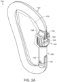
- Figure 2A-B illustrate a perspective system view and a detailed locking system view of the system 100 illustrated in Figure 1B .
- Figure 2A illustrates the system 100 with the gate 140 in the closed state and the locking system 160 in the unlocked state 160.
- the unlocked state 160 of the locking system 160 requires that a user apply rotational forces shown in Figure 1B to separate the latching sleeves 162, 164 and expose the recess 170.
- Figure 2B illustrates the locking system 160 in the unlocked state with the recess 170 exposed.
- Figure 2B illustrates one embodiment of the latching sleeves 162, 164 geometry, including the substantially internested rotational coupling and pin 168 for restricting rotational freedom.
- the latching sleeves 162, 164 are included to facilitate the rotational intercoupling, the recess 170, and notch 172.
- the latching sleeves 162, 164 may optionally include additional external flanges to enhance friction for better user grip.
- the recess 170 is specifically shaped to correspond with the gate recess 146 and gate frame coupling region 124.
- the notch 172 is a substantially concave shape formed in part by both latching sleeves 162, 164. In the illustrated unlocked state, the two portions of the notch 172 are separated.
- the illustrated lock biasing spring 166 is a torsion spring disposed at the bottom of the latching sleeves 162, 164 to bias the latching sleeves 162, 164 together to form the locked state.
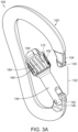
- Figure 3A illustrates the system 100 with the gate 140 in the open state and the latching sleeves 162, 164 rotated together.
- the open state of the gate 140 requires a user to selectively unlock the locking system 160 via rotational forces ( Figure 1B ) and pivot the gate 140 via a pivot force ( Figure 1C ).
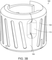
- Figure 3B illustrates the latching sleeves 162, 164 rotated together but the overall system is in the open state.
- the locked state of the system 100 only includes the latching sleeves 162, 164 rotated together and the gate 140 in the closed state ( Figure 1A ).
- the latching sleeves 162, 164 are releasably forced together by the lock biasing spring 166.
- the recess 170 is therefore blocked, and the notch 172 is completely formed.
- the notch 172 requires the latching sleeves 162, 164 to be rotated together so as to couple the portions of the notch 172.
- the particular geometry and internal curvatures of the notch 172 correspond to the ramped surface 125 and the gate frame coupling region 124 of the frame 120. It will be appreciated that various alternative geometries of the notch 172 and ramped surface 125 have been contemplated as alternative embodiments. In particular, the correspondence between the notch 172 and the ramped surface 125 affect the operation, efficiency, and reliability of the automatic relocking of the locking system 160 when all forces are removed in the open state and the gate 140 is allowed the return to the closed state.
- Figure 4 illustrates an exploded view of the gate and locking system components of the embodiments illustrated in Figures 1-3 .
- the exploded view illustrates one embodiment of the components of the gate 140 and locking system 160 to enable the automatic locking functionality described above.
- the substantially cylindrical shape of the latching sleeves 162, 164 is illustrated. It will also be apparent that the shape of each of the latching sleeves 162, 164 is configured to correspond to each other to facilitate the internested and rotational coupling.
- the positioning of the lock biasing spring 166 will also be appreciated to facilitate the biasing of the latching sleeves 162, 164 radially together to engage the locked state.
- the positioning of the locking system 160 in substantial proximity to the second end 144 of the gate 140 and over the gate recess 146 should also be appreciated from the exploded view.
- the pins 168 may optionally constrain the rotational freedom of the latching sleeves 162, 164 in some form of internal channel between the latching sleeves 162, 164.
Landscapes
- Engineering & Computer Science (AREA)
- General Engineering & Computer Science (AREA)
- Mechanical Engineering (AREA)
- Hooks, Suction Cups, And Attachment By Adhesive Means (AREA)
Description
- The invention generally relates to locking carabiners. In particular, the present invention relates to systems and methods of automatic carabiner gate locking.
- Carabiners, snap-hooks, and releasable clamps are used in a variety of applications for releasably coupling objects to one another. For example, a rock climber may use one or more carabiners to releasably secure a rope to a protection device during vertical ascension. Carabiners generally include a frame, a gate, and a releasable gate closure mechanism. The gate is configured to releasably engage the frame, so as to form a continuous inner region which can be used to mechanically couple to one or more objects. The releasable gate closure mechanism is configured to allow the gate to be selectively pivoted with respect to the frame to facilitate adding or removing items from the continuous inner region. The releasable gate closure mechanism simultaneously biases the gate toward a closed configuration with respect to the frame, so as to maintain mechanical coupling of items within the continuous inner region. A wide variety of frame, gate, and biasing systems exist to specifically accommodate particular applications and/or manufacturing costs for the carabiner.
- Various specialized carabiners are designed for particular applications. One type of specialized carabiner includes a locking gate mechanism having a locked state and an unlocked state commonly referred to as a locking carabiner. Locking carabiners may be used to lock the gate in a closed configuration with respect to the frame. A locked carabiner gate reduces and/or avoids unintended gate opening. For example, unintended carabiner gate openings may occur as a result of certain forces acting upon a carabiner, including but not limited to cross-loading gate forces, vibration forces, and other unforeseen acute events such as lateral obstruction forces in a falling scenario. A locking carabiner generally includes any type of carabiner frame with a locking gate mechanism. A particular type of locking carabiner is an autolocking carabiner, meaning that the locking mechanism includes biasing toward the locked state. Automatically locking the locking mechanism means that when a user selectively opens the carabiner gate and subsequently releases the gate, the gate automatically returns to both the closed configuration and the locked state. Another type of carabiner includes a key-lock or notchless locking carabiner. A key-lock carabiner includes a notchless or hookless coupling between the gate and the frame in the closed position. This type of coupling is preferable because it avoids unintended snagging or catching of the carabiner frame in an open gate configuration. Therefore, a key-lock automatic locking carabiner is particularly desirable because it eliminates unintended gate opening via the locking mechanism, automatically relocks the locking mechanism after opening, and eliminates unintended gate frame snagging via the key-lock/geometrical coupling between the frame and the gate.
- Various problems exist with conventional automatic locking key-lock carabiners (autolocking carabiners). One common problem is that carabiner locking mechanisms are often overly cumbersome to operate. An example thereof is the locking mechanism of the carabiner described in
GB-A 2503737 - Therefore, there is a need in the industry for a locking carabiner system that minimizes unintended opening scenarios, provides efficient and intuitive operation, and overcomes the limitations of existing systems in a cost-efficient manner.
- The present invention relates to locking carabiners. One embodiment of the present invention relates to an automatic locking carabiner system according to claim 1. The system includes a frame, a gate, a gate biasing system, and a gate locking system. The gate locking system further includes a set of rotatable latching sleeves disposed over the gate. When the gate is in the closed state, the latching sleeves independently rotate between an unlocked state in which the gate is free to pivot and a locked state in which the gate may be prevented from pivoting with respect to the frame. The locked state further includes rotationally orienting the latching sleeves over the gate frame coupling region. The unlocked state further includes rotationally separating the latching sleeves to expose a locking recess over the gate recess, thereby allowing the gate to pivot. A second embodiment of the present invention relates to a method of automatically locking a carabiner according to claim 13, including automatically engaging a locking system and selectively disengaging the locking system to allow the gate to pivot.
- Embodiments of the present invention represent a significant advancement in the field of automatic carabiner gate locking systems. Conventional automatic gate locking systems incorporate a single rotating sleeve biased toward a locked state, requiring a user to selectively twist and/or slide the locking mechanism to disengage the lock. In contrast, embodiments of the present invention provide an intuitive dual-rotation disengagement of the locking system. A user may reliably disengage the locking mechanism with two fingers, without requiring repositioning of the hand with respect to the carabiner and gate, when performing multi-step unlocking sequences. Likewise, the automatic relocking of the system in the open state is both reliable and efficient.
- These and other features and advantages of the present invention will be set forth or will become more fully apparent in the description that follows and in the appended claims. The features and advantages may be realized and obtained by means of the instruments and combinations particularly pointed out in the appended claims. Furthermore, the features and advantages of the invention may be learned by the practice of the invention or will be obvious from the description, as set forth hereinafter.
- The following description of the invention can be understood in light of the Figures, which illustrate specific aspects of the invention and are a part of the specification. Together with the following description, the Figures demonstrate and explain the principles of the invention. In the Figures, the physical dimensions may be exaggerated for clarity. The same reference numerals in different drawings represent the same element, and thus their descriptions will be omitted.
-
Figures 1A-C illustrate a perspective views of an automatic locking carabiner system in a closed locked state, a closed unlocked state, and an open state in accordance with embodiments of the present invention; -
Figures 2A-B illustrate a perspective and detailed view of the embodiment illustrated in -
Figure 1B in the closed unlocked state in accordance with embodiments of the present invention; -
Figures 3A-B illustrate a perspective and detailed view of the embodiment illustrated in -
Figure 1C in the open state in accordance with embodiments of the present invention; and -
Figure 4 illustrates an exploded view of the gate and locking system components of -
Figures 1-3 in accordance with one embodiment of the present invention. - The present invention relates to locking carabiners. One embodiment of the present invention relates to an automatic locking carabiner system and method of operation. The system includes a frame, a gate, a gate biasing system, and a gate locking system. The gate locking system further includes a set of rotatable latching sleeves disposed over the gate. When the gate is in the closed state, the latching sleeves independently rotate between an unlocked state in which the gate is free to pivot and a locked state in which the gate may beprevented from pivoting with respect to the frame. The locked state further includes rotationally orienting the latching sleeves over the gate frame coupling region. The unlocked state further includes rotationally separating the latching sleeves to expose a locking recess over the gate recess, thereby allowing the gate to pivot. A second embodiment of the present invention relates to a method of automatically locking a carabiner, including automatically engaging a locking system and selectively disengaging the locking system to allow the gate to pivot.
- Reference is initially made to
Figures 1A-C , which illustrate three different states of one embodiment of an automatic locking carabiner system, designated generally at 100.Figure 1A illustrates thesystem 100 in a closed locked state, whileFigure 1B is in a closed unlocked state andFigure 1C is in an open state. Thesystem 100 includes aframe 120, agate 140, and agate locking system 160. Theframe 120 is a substantially C-shaped member having an opening 122 (Figure 3A ), a gate frame coupling region 124 (Figure 3A ), and a gate pivot location 126 (Figure 3A ). Although the illustrated embodiment includes a D-shapedframe 120, it will be appreciated that embodiments of the present invention may include an alternative frame style, including but not limited to oval, circular, and triangular shaped frames of various sizes. Theframe 120 may comprise a substantially rigid material including but not limited to aluminum, plastic, and/or steel. Theframe 120 is preferably composed of a single continuous member. Theopening 122 extends between the gateframe coupling region 124 and thegate pivot location 126. The size of theopening 122 corresponds to the length of thegate 140. The illustrated gateframe coupling region 124 includes a geometrical male region corresponding to thegate recess 146 which will be described in more detail below. The gateframe coupling region 124 may also be referred to as a key-lock, notchless, or hookless coupling region. It is preferable to avoid the use of a hook or notch so as to avoid snagging the gateframe coupling region 124 when the gate is in the open state (Figure 1C and3A ). The specific shape of the illustrated gateframe coupling region 124 is an inverted T-shape with at least one ramped surface 125 (Figure 3A ). The rampedsurface 125 corresponds to anotch 172 on thelocking system 160 and will be described in more detail below. The inverted T-shape corresponds to thegate recess 146 to facilitate the male-female releasable coupling of theframe 120 andgate 140 in the closed state (Figures 1A, 1B ,2A ). - The
gate 140 extends across theopening 122 of theframe 120 in the closed state (Figures 1A, 1B ). Thegate 140 is an elongated member having afirst end 142 pivotably coupled to theframe 120 at thegate pivot location 126. Thegate 140 further includes asecond end 144 which is releasably coupled to theframe 120 at the gateframe coupling region 124 in the closed state. The closed state of thegate 140 forms an enclosed region 102 (Figure 2A ) within theframe 120 andgate 140. The closed state further includes a releasable geometric coupling between the second end of thegate 144 and the gateframe coupling region 124 of the frame. Thegate 140 further includes an internal gate biasing spring which biases thegate 140 toward the closed state. The second end of thegate 144 includes agate recess 146 geometrically corresponding to the gateframe coupling region 124. In the closed state, the male shape of the gateframe coupling region 124 is substantially disposed within the female shape of thegate recess 146. The female shape of thegate recess 146 may include a taper or closed portion so as to prevent thegate 140 from pivoting away from theframe 120.Figure 1C illustrates an internal force arrow representing that in operation a user may apply the internal force upon thegate 140 to overcome the gate biasing spring and transition thegate 140 from the closed state (Figures 1A, 1B ,2A ) to the open state (Figure 1C ,3A ). - The
novel locking system 160 is disposed on thegate 140 in substantial proximity to thesecond end 144 as illustrated. Thelocking system 160 is configured to automatically lock thegate 140 in the closed state, herein referred to as the locked state of thelocking system 160. Thelocking system 160 includes a set of latchingsleeves lock biasing spring 166, at least onepin 168, arecess 170, and anotch 172. The individual components of thelocking system 162 are illustrated in all figures including individually in the exploded view ofFigure 4 . The illustrated latchingsleeves sleeves sleeves pin 168, or it may include specific geometries. Thelock biasing spring 166 biases the rotational position of the latchingsleeves locking system 160 as shown inFigures 1A ,2A ,2B . The specific rotational orientation and freedom of the latchingsleeves sleeves lock biasing spring 166 biases the latchingsleeves sleeves locking system 160 from the locked state to the unlocked state.Figure 1B illustrates two rotational force arrows representing the two simultaneous forces which must be independently applied to the latchingsleeves lock biasing spring 166 and transition thelocking system 160 from the locked state to the unlocked state. The unlocked state of the locking system shown inFigure 1B includes exposing therecess 170 of thelocking system 160. Therecess 170 may be formed as part of the latching sleeve geometry. The positioning of thelocking system 160 is configured such that therecess 170 is disposed over the gateframe coupling region 124 and thegate recess 146 in the unlocked state. The size and shape of therecess 170 corresponds to both the gateframe coupling region 124 and thegate recess 146 to allow the second end of thegate 144 to pivot within theenclosed region 102 in the open state. However, as soon as the independent rotational forces (Figure 1B ) are removed from the latchingsleeves Figure 1C ) is applied on thegate 140, the latchingsleeves Figure 1C . Although the , latchingsleeves system 100 is not locked because thegate 140 is free to rotate. When the pivoting force (1C) is removed from thegate 140, the gate biasing spring will cause thegate 140 to pivot back to the closed state. Thelocking system 160 includes anotch 172 formed in part by both of the latchingsleeves notch 172 geometrically corresponds to the gateframe coupling region 124 and rampedsurface 125 of theframe 120 to automatically rotate the latchingsleeves gate 140 pivots from the open state (Figure 1C ) to the closed state (Figure 1A ). In particular, the rampedsurface 125 acts as a wedge in thenotch 172 to separate the latchingsleeves gate 140 to pivot back to the closed state. This process may be referred to as the automatic re-locking of thegate 140, as all forces are released and thegate 140 is in the open state. When all forces are released and thegate 140 is in the open state, the gate biasing spring will urge the gate toward the closed state, and the rampedsurface 125 wedges apart the latchingsleeves locking system 160 and automatically return thesystem 100 to the closed and locked state. - Reference is next made to
Figures 2A-B , which illustrate a perspective system view and a detailed locking system view of thesystem 100 illustrated inFigure 1B .Figure 2A illustrates thesystem 100 with thegate 140 in the closed state and thelocking system 160 in theunlocked state 160. As described above, theunlocked state 160 of thelocking system 160 requires that a user apply rotational forces shown inFigure 1B to separate the latchingsleeves recess 170.Figure 2B illustrates thelocking system 160 in the unlocked state with therecess 170 exposed.Figure 2B illustrates one embodiment of the latchingsleeves sleeves recess 170, and notch 172. The latchingsleeves recess 170 is specifically shaped to correspond with thegate recess 146 and gateframe coupling region 124. Thenotch 172 is a substantially concave shape formed in part by both latchingsleeves notch 172 are separated. The illustratedlock biasing spring 166 is a torsion spring disposed at the bottom of the latchingsleeves sleeves - Reference is next made to
Figures 3A-B , which illustrate a perspective system view and a detailed locking system view of the system illustrated inFigure 1C .Figure 3A illustrates thesystem 100 with thegate 140 in the open state and the latchingsleeves gate 140 requires a user to selectively unlock thelocking system 160 via rotational forces (Figure 1B ) and pivot thegate 140 via a pivot force (Figure 1C ).Figure 3B illustrates the latchingsleeves system 100 only includes the latchingsleeves gate 140 in the closed state (Figure 1A ). The latchingsleeves lock biasing spring 166. Therecess 170 is therefore blocked, and thenotch 172 is completely formed. As described above, thenotch 172 requires the latchingsleeves notch 172. The particular geometry and internal curvatures of thenotch 172 correspond to the rampedsurface 125 and the gateframe coupling region 124 of theframe 120. It will be appreciated that various alternative geometries of thenotch 172 and rampedsurface 125 have been contemplated as alternative embodiments. In particular, the correspondence between thenotch 172 and the rampedsurface 125 affect the operation, efficiency, and reliability of the automatic relocking of thelocking system 160 when all forces are removed in the open state and thegate 140 is allowed the return to the closed state. - Reference is next made to
Figure 4 , which illustrates an exploded view of the gate and locking system components of the embodiments illustrated inFigures 1-3 . The exploded view illustrates one embodiment of the components of thegate 140 and lockingsystem 160 to enable the automatic locking functionality described above. The substantially cylindrical shape of the latchingsleeves sleeves lock biasing spring 166 will also be appreciated to facilitate the biasing of the latchingsleeves locking system 160 in substantial proximity to thesecond end 144 of thegate 140 and over thegate recess 146 should also be appreciated from the exploded view. Thepins 168 may optionally constrain the rotational freedom of the latchingsleeves sleeves - It should be noted that various alternative system designs may be practiced in accordance with the present invention within the scope of the appended claims, including one or more portions or concepts of the embodiment illustrated in
Figure 1 or described above. Various other embodiments have been contemplated, including combinations in whole or in part of the embodiments described above.
Claims (17)
- An automatic locking carabiner system (100) comprising:a frame (120) including a gate frame coupling region (124), a pivot location (126), and an opening (122) between the gate frame coupling region (124) and the pivot location (126);a gate (140) having a first end (142) pivotably coupled about the pivot location (126) to the frame (120), wherein the gate (140) includes a second end (144);a closed state in which the gate (140) and the frame (120) form an enclosed region (102), wherein the second end (144) of the gate is releasably coupled to the frame (120) at the gate frame coupling region (124);an open state in which the second end (144) of the gate is pivotably rotated within the enclosed region (102);a gate biasing system configured to bias the gate toward the closed state;a gate locking system (160) disposed on the gate (140) in substantial proximity to the second end (144) of the gate including:a set of latching sleeves (162, 164) rotatably coupled to the gate (140), wherein the latching sleeves are configured to rotate;a locked state in which the gate (140) is in the closed state and the gate (140) is prevented from pivoting with respect to the frame (120), wherein the locked state further includes orienting the rotational positioning of at least one of the latching sleeves (162, 164) over the gate frame coupling region (124) of the frame;an unlocked state in which the gate (140) is in the closed state and the gate (140) is free to pivot with respect to the frame (120), wherein the unlocked state further includes orienting the rotational positioning of latching sleeves (162, 164) to create a recess through which the gate frame coupling region (124) of the frame may translate; anda lock biasing system biasing the gate locking system toward the locked state;characterized in thatthe latching sleeves (162, 164) are configured to independently rotate in opposite directions away from one another from the locked state.
- The system of claim 1, wherein the gate frame coupling region (124) is notchless and hookless.
- The system of claim 1, wherein the second end (144) of the gate includes a coupling region geometrically corresponding to the gate frame coupling region (124) of the frame.
- The system of claim 1, wherein the second end (144) of the gate includes a gate recess (146) geometrically corresponding to the frame coupling region (124) of the frame.
- The system of claim 1, wherein the gate locking system (160) is disposed circumferentially over the gate (140).
- The system of claim 1, wherein the latching sleeves (162, 164) are substantially cylindrically shaped and overlapping.
- The system of claim 1, wherein the latching sleeves (162, 164) are internested and intercoupled with one another.
- The system of claim 1, wherein the second end (144) of the gate includes a gate recess (146) and the latching sleeves (162, 164) are configured to create a recess (170) over the gate recess (146) in the unlocked state.
- The system of claim 1, wherein the gate biasing system includes a torsion spring (166) configured to rotationally bias the latching sleeves (162, 164) to the locked state.
- The system of claim 1, wherein the latching sleeves (162, 164) are internested and intercoupled with at least one pin (168) configured to constrain the inter-rotational freedom between the latching sleeves (162, 164).
- The system of claim 1, wherein the gate frame coupling region (124) includes a ramped surface (125) configured to temporarily unlock the locking system (160) when the gate (140) is released in the open state and returned to the closed state via the gate biasing system.
- The system according to claim 1
wherein the gate locking system (160) is circumferentially disposed over the gate (140) in substantial proximity to the second end (144) of the gatewherein the latching sleeves (162, 164) are overlapping;a locked state in which the gate is in the closed state and the gate is prevented from pivoting with respect to the frame, wherein the locked state further includes orienting the rotational positioning of the latching sleeves (162, 164) over the gate frame coupling region (124) of the frame;an unlocked state in which the gate is in the closed state and the gate is free to pivot with respect to the frame, wherein the unlocked state further includes orienting the rotational positioning of latching sleeves to create a recess through which the gate frame coupling region of the frame may translate, wherein the second end (144) of the gate includes a gate recess (146) and the latching sleeves (162, 164) are configured to create a recess (170) over the gate recess (146) in the unlocked state; anda lock biasing system biasing the gate locking system toward the locked state. - A method for automatically locking a carabiner comprising the acts of:providing a frame including a gate frame coupling region (124), a pivot location (126), and an opening (122) between the gate frame coupling region (124) and the pivot location (126);providing a gate (140) having a first end (142) pivotably coupled about the pivot location (126) to the frame (120), wherein the gate (140) includes a second end (144);providing a closed state in which the gate (140) and the frame (120) form an enclosed region (102), wherein the second end (144) of the gate is releasably coupled to the frame (120) at the gate frame coupling region (124);providing an open state in which the second end (144) of the gate is pivotably rotated within the enclosed region (102);providing a gate biasing system configured to bias the gate toward the closed state;providing a gate locking system (160) disposed on the gate (140) in substantial proximity to the second end (144) of the gate including:
a set of latching sleeves (162, 164) rotatably coupled to the gate (140),wherein the latching sleeves are configured to rotate;automatically engaging a locked state in which the gate (140) is in the closed state and the gate (140) is prevented from pivoting with respect to the frame (120), wherein the locked state further includes orienting the rotational positioning of the latching sleeves (162, 164) over the gate frame coupling region (124) of the frame;wherein the automatic engagement of the locked state includes rotationally biasing the latching sleeves (162, 164) together;selectively engaging an unlocked state in which the gate (140) is free to pivot with respect to the frame (120), wherein the unlocked state further includes orienting the rotational positioning of latching sleeves (162, 164) to create a recess (170) through which the gate frame coupling region (124) of the frame may translate;characterized in thatthe act of selectively engaging an unlocked state in which the gate (140) is free to pivot with respect to the frame (120) includes independently rotating the latching sleeves (162, 164) to expose a recess (170) over a gate recess (146) on the second end (144) of the gate. - The method of claim 13, wherein the act of selectively engaging an unlocked state includes independently rotating the latching sleeves (162, 164) away from one another.
- The method of claim 13, wherein the automatic engagement of the locked state includes rotationally biasing the latching sleeves (162, 164) toward one another.
- The method of claim 13, wherein the second end (144) of the gate includes a coupling region geometrically corresponding to the gate frame coupling region (124) of the frame.
- The method of claim 13, wherein the gate locking system (160) is disposed circumferentially over the gate (140).
Applications Claiming Priority (1)
| Application Number | Priority Date | Filing Date | Title |
|---|---|---|---|
| US17/130,240 US11286973B1 (en) | 2020-12-22 | 2020-12-22 | Systems and methods for carabiner gate automatic locking |
Publications (2)
| Publication Number | Publication Date |
|---|---|
| EP4019792A1 EP4019792A1 (en) | 2022-06-29 |
| EP4019792B1 true EP4019792B1 (en) | 2024-03-27 |
Family
ID=78806316
Family Applications (1)
| Application Number | Title | Priority Date | Filing Date |
|---|---|---|---|
| EP21210700.7A Active EP4019792B1 (en) | 2020-12-22 | 2021-11-26 | Systems and methods for carabiner gate automatic locking |
Country Status (2)
| Country | Link |
|---|---|
| US (1) | US11286973B1 (en) |
| EP (1) | EP4019792B1 (en) |
Families Citing this family (3)
| Publication number | Priority date | Publication date | Assignee | Title |
|---|---|---|---|---|
| USD1039938S1 (en) * | 2022-04-08 | 2024-08-27 | Trayvax Enterprises Llc | Keychain multitool |
| US20240399191A1 (en) * | 2023-03-28 | 2024-12-05 | Exemplar Design, Llc | Suspended Body Weight Trainer |
| USD1023717S1 (en) * | 2023-06-10 | 2024-04-23 | Weihong GUAN | Multi-tool knife |
Family Cites Families (30)
| Publication number | Priority date | Publication date | Assignee | Title |
|---|---|---|---|---|
| US7540074B2 (en) * | 2004-12-21 | 2009-06-02 | Techxotic, L.C. | Carabiner having reinforcing sleeve |
| US9382939B1 (en) | 2009-04-03 | 2016-07-05 | Buckingham Manufacturing Company, Inc. | Linkless attachment arrangement for a locking snap-hook or the like |
| US9003617B2 (en) | 2009-12-11 | 2015-04-14 | Black Diamond Equipment Ltd. | Multi-chamber carabiner |
| US8276247B2 (en) * | 2010-07-13 | 2012-10-02 | Gimmal Co., Ltd. | Snap hook with rotatable lock |
| US9273717B2 (en) | 2011-10-27 | 2016-03-01 | D B Industries, Llc | Connector for lifelines |
| US8752254B2 (en) | 2012-02-28 | 2014-06-17 | D B Industries, Llc | Snap hook |
| CN202456777U (en) | 2012-03-07 | 2012-10-03 | 阳江市纳丽德工贸有限公司 | Hook with lock |
| US9441665B2 (en) | 2012-03-07 | 2016-09-13 | Nite Ize, Inc. | Systems and methods for a locking carabineer |
| GB2503737B (en) * | 2012-07-06 | 2014-10-15 | Dmm Internat Ltd | Carabiner |
| TWM452269U (en) * | 2012-09-25 | 2013-05-01 | Neng-Yuan Ye | Safety hook structure |
| FI125688B (en) | 2013-01-11 | 2016-01-15 | Konecranes Global Oy | Lifting hook, safety latch for a lifting hook and locking and release device for a safety latch |
| US9322428B2 (en) * | 2013-03-01 | 2016-04-26 | D B Industries, Llc | Locking carabiner |
| AU2014268120B2 (en) * | 2013-05-15 | 2017-10-05 | Andrew ROGELJA | Improvements in karabiners |
| US20140361564A1 (en) * | 2013-06-05 | 2014-12-11 | Chin-Shun Huang | Hook-Pulley Combination |
| US9470258B2 (en) | 2013-09-10 | 2016-10-18 | ACCO Brands Corporation | Carabiner including a lock mechanism |
| ITMI20131544A1 (en) | 2013-09-19 | 2015-03-20 | Camp Spa | CARABINER WITH KEY-LOCK SYSTEM |
| US9212688B2 (en) | 2013-10-28 | 2015-12-15 | James Jang | Snap ring having multiple rollers |
| US9039055B1 (en) | 2013-11-25 | 2015-05-26 | Terry K. Robins | Clevis type hook with safety latch |
| EP3116819B1 (en) | 2014-03-10 | 2019-10-16 | Konecranes Global Corporation | Lifting hook, safety latch of lifting hook and locking and releasing device of safety latch |
| US9267535B2 (en) | 2014-07-15 | 2016-02-23 | James Jang | Snap ring having easily replaceable support |
| BR112017011720B1 (en) | 2014-12-05 | 2021-06-22 | Ferplast S.P.A. | SELF-LOCKING SAFETY SPRING CLOSURE |
| US9500221B2 (en) | 2015-03-25 | 2016-11-22 | Aerohook Technology Co., Ltd. | Triple locking hook connector |
| TWI570331B (en) | 2015-05-19 | 2017-02-11 | Zhan Yi-Rong | Flexible compression mechanism |
| US10066660B2 (en) | 2015-10-22 | 2018-09-04 | Reliance Industries, Llc | Rebar snap hook |
| US10514057B2 (en) * | 2017-05-05 | 2019-12-24 | Tammie Cardella | Cushioned carabiner clip |
| US9958002B2 (en) | 2016-07-18 | 2018-05-01 | Win Chance Metal Co., Ltd. | Dust-proof safety hook |
| US9878884B1 (en) * | 2016-11-23 | 2018-01-30 | International Safety Components Ltd | Pulley systems for hauling or lowering loads |
| US20180320729A1 (en) | 2017-05-03 | 2018-11-08 | Black Diamond Equipment, Ltd. | Carabiner systems and methods |
| USD848823S1 (en) * | 2018-01-19 | 2019-05-21 | Milwaukee Electric Tool Corporation | Carabiner |
| USD902009S1 (en) * | 2019-05-05 | 2020-11-17 | Dongguan Guofeng Manufacture CO., LTD | Combination lock carabiner |
-
2020
- 2020-12-22 US US17/130,240 patent/US11286973B1/en active Active
-
2021
- 2021-11-26 EP EP21210700.7A patent/EP4019792B1/en active Active
Also Published As
| Publication number | Publication date |
|---|---|
| US11286973B1 (en) | 2022-03-29 |
| EP4019792A1 (en) | 2022-06-29 |
Similar Documents
| Publication | Publication Date | Title |
|---|---|---|
| EP4019792A1 (en) | Systems and methods for carabiner gate automatic locking | |
| EP1927767B1 (en) | Improved safety carabiner | |
| US9003617B2 (en) | Multi-chamber carabiner | |
| EP2527670B1 (en) | Magnetic carabiner system | |
| EP3678507B1 (en) | Harness connector | |
| TWI767028B (en) | Fall arresting device connector, system, and method | |
| EP2997270B1 (en) | Improvements in karabiners | |
| CN104736784B (en) | Mixing lock core | |
| US5613381A (en) | Handcuff | |
| US20010005077A1 (en) | Padlock | |
| CN110382881B (en) | Anchor assembly for a fastener | |
| EP2777772A2 (en) | Systems for assisted braking belay with a lever disengagement mechanism | |
| MX2010011858A (en) | Locking clamp. | |
| US20190069644A1 (en) | Harness Connector | |
| EP0352948A2 (en) | Releasable gripping, locking, coupling or support devices | |
| EP1143188A2 (en) | Tube connecting device | |
| EP3573205B1 (en) | Clamping device configured to hold one or more longitudinal elements | |
| US5001912A (en) | Lockable meter clamp ring | |
| AU2022459561B2 (en) | Safety shackle | |
| US11009159B2 (en) | Visual and tactile latch indicator for a fuel system coupling | |
| EP3050450B1 (en) | Locking clip and anchor assembly for a tether | |
| JP7808924B2 (en) | A coupling device for connecting a load to a sling by means of a support bolt | |
| WO2004013438A1 (en) | Restricting device | |
| EP3824155B1 (en) | Lock mechanism | |
| EP3908471A1 (en) | Starting device for a motorcycle |
Legal Events
| Date | Code | Title | Description |
|---|---|---|---|
| PUAI | Public reference made under article 153(3) epc to a published international application that has entered the european phase |
Free format text: ORIGINAL CODE: 0009012 |
|
| STAA | Information on the status of an ep patent application or granted ep patent |
Free format text: STATUS: THE APPLICATION HAS BEEN PUBLISHED |
|
| AK | Designated contracting states |
Kind code of ref document: A1 Designated state(s): AL AT BE BG CH CY CZ DE DK EE ES FI FR GB GR HR HU IE IS IT LI LT LU LV MC MK MT NL NO PL PT RO RS SE SI SK SM TR |
|
| STAA | Information on the status of an ep patent application or granted ep patent |
Free format text: STATUS: REQUEST FOR EXAMINATION WAS MADE |
|
| 17P | Request for examination filed |
Effective date: 20230102 |
|
| RBV | Designated contracting states (corrected) |
Designated state(s): AL AT BE BG CH CY CZ DE DK EE ES FI FR GB GR HR HU IE IS IT LI LT LU LV MC MK MT NL NO PL PT RO RS SE SI SK SM TR |
|
| P01 | Opt-out of the competence of the unified patent court (upc) registered |
Effective date: 20230530 |
|
| GRAP | Despatch of communication of intention to grant a patent |
Free format text: ORIGINAL CODE: EPIDOSNIGR1 |
|
| STAA | Information on the status of an ep patent application or granted ep patent |
Free format text: STATUS: GRANT OF PATENT IS INTENDED |
|
| INTG | Intention to grant announced |
Effective date: 20240109 |
|
| GRAS | Grant fee paid |
Free format text: ORIGINAL CODE: EPIDOSNIGR3 |
|
| GRAA | (expected) grant |
Free format text: ORIGINAL CODE: 0009210 |
|
| STAA | Information on the status of an ep patent application or granted ep patent |
Free format text: STATUS: THE PATENT HAS BEEN GRANTED |
|
| AK | Designated contracting states |
Kind code of ref document: B1 Designated state(s): AL AT BE BG CH CY CZ DE DK EE ES FI FR GB GR HR HU IE IS IT LI LT LU LV MC MK MT NL NO PL PT RO RS SE SI SK SM TR |
|
| REG | Reference to a national code |
Ref country code: GB Ref legal event code: FG4D |
|
| REG | Reference to a national code |
Ref country code: CH Ref legal event code: EP |
|
| REG | Reference to a national code |
Ref country code: DE Ref legal event code: R096 Ref document number: 602021010909 Country of ref document: DE |
|
| REG | Reference to a national code |
Ref country code: IE Ref legal event code: FG4D |
|
| PG25 | Lapsed in a contracting state [announced via postgrant information from national office to epo] |
Ref country code: LT Free format text: LAPSE BECAUSE OF FAILURE TO SUBMIT A TRANSLATION OF THE DESCRIPTION OR TO PAY THE FEE WITHIN THE PRESCRIBED TIME-LIMIT Effective date: 20240327 |
|
| REG | Reference to a national code |
Ref country code: LT Ref legal event code: MG9D |
|
| PG25 | Lapsed in a contracting state [announced via postgrant information from national office to epo] |
Ref country code: GR Free format text: LAPSE BECAUSE OF FAILURE TO SUBMIT A TRANSLATION OF THE DESCRIPTION OR TO PAY THE FEE WITHIN THE PRESCRIBED TIME-LIMIT Effective date: 20240628 |
|
| PG25 | Lapsed in a contracting state [announced via postgrant information from national office to epo] |
Ref country code: RS Free format text: LAPSE BECAUSE OF FAILURE TO SUBMIT A TRANSLATION OF THE DESCRIPTION OR TO PAY THE FEE WITHIN THE PRESCRIBED TIME-LIMIT Effective date: 20240627 Ref country code: HR Free format text: LAPSE BECAUSE OF FAILURE TO SUBMIT A TRANSLATION OF THE DESCRIPTION OR TO PAY THE FEE WITHIN THE PRESCRIBED TIME-LIMIT Effective date: 20240327 |
|
| PG25 | Lapsed in a contracting state [announced via postgrant information from national office to epo] |
Ref country code: RS Free format text: LAPSE BECAUSE OF FAILURE TO SUBMIT A TRANSLATION OF THE DESCRIPTION OR TO PAY THE FEE WITHIN THE PRESCRIBED TIME-LIMIT Effective date: 20240627 Ref country code: NO Free format text: LAPSE BECAUSE OF FAILURE TO SUBMIT A TRANSLATION OF THE DESCRIPTION OR TO PAY THE FEE WITHIN THE PRESCRIBED TIME-LIMIT Effective date: 20240627 Ref country code: LT Free format text: LAPSE BECAUSE OF FAILURE TO SUBMIT A TRANSLATION OF THE DESCRIPTION OR TO PAY THE FEE WITHIN THE PRESCRIBED TIME-LIMIT Effective date: 20240327 Ref country code: HR Free format text: LAPSE BECAUSE OF FAILURE TO SUBMIT A TRANSLATION OF THE DESCRIPTION OR TO PAY THE FEE WITHIN THE PRESCRIBED TIME-LIMIT Effective date: 20240327 Ref country code: GR Free format text: LAPSE BECAUSE OF FAILURE TO SUBMIT A TRANSLATION OF THE DESCRIPTION OR TO PAY THE FEE WITHIN THE PRESCRIBED TIME-LIMIT Effective date: 20240628 Ref country code: FI Free format text: LAPSE BECAUSE OF FAILURE TO SUBMIT A TRANSLATION OF THE DESCRIPTION OR TO PAY THE FEE WITHIN THE PRESCRIBED TIME-LIMIT Effective date: 20240327 Ref country code: BG Free format text: LAPSE BECAUSE OF FAILURE TO SUBMIT A TRANSLATION OF THE DESCRIPTION OR TO PAY THE FEE WITHIN THE PRESCRIBED TIME-LIMIT Effective date: 20240327 |
|
| REG | Reference to a national code |
Ref country code: NL Ref legal event code: MP Effective date: 20240327 |
|
| PG25 | Lapsed in a contracting state [announced via postgrant information from national office to epo] |
Ref country code: SE Free format text: LAPSE BECAUSE OF FAILURE TO SUBMIT A TRANSLATION OF THE DESCRIPTION OR TO PAY THE FEE WITHIN THE PRESCRIBED TIME-LIMIT Effective date: 20240327 Ref country code: LV Free format text: LAPSE BECAUSE OF FAILURE TO SUBMIT A TRANSLATION OF THE DESCRIPTION OR TO PAY THE FEE WITHIN THE PRESCRIBED TIME-LIMIT Effective date: 20240327 |
|
| PG25 | Lapsed in a contracting state [announced via postgrant information from national office to epo] |
Ref country code: NL Free format text: LAPSE BECAUSE OF FAILURE TO SUBMIT A TRANSLATION OF THE DESCRIPTION OR TO PAY THE FEE WITHIN THE PRESCRIBED TIME-LIMIT Effective date: 20240327 |
|
| REG | Reference to a national code |
Ref country code: AT Ref legal event code: MK05 Ref document number: 1670180 Country of ref document: AT Kind code of ref document: T Effective date: 20240327 |
|
| PG25 | Lapsed in a contracting state [announced via postgrant information from national office to epo] |
Ref country code: NL Free format text: LAPSE BECAUSE OF FAILURE TO SUBMIT A TRANSLATION OF THE DESCRIPTION OR TO PAY THE FEE WITHIN THE PRESCRIBED TIME-LIMIT Effective date: 20240327 |
|
| PG25 | Lapsed in a contracting state [announced via postgrant information from national office to epo] |
Ref country code: IS Free format text: LAPSE BECAUSE OF FAILURE TO SUBMIT A TRANSLATION OF THE DESCRIPTION OR TO PAY THE FEE WITHIN THE PRESCRIBED TIME-LIMIT Effective date: 20240727 |
|
| PG25 | Lapsed in a contracting state [announced via postgrant information from national office to epo] |
Ref country code: PT Free format text: LAPSE BECAUSE OF FAILURE TO SUBMIT A TRANSLATION OF THE DESCRIPTION OR TO PAY THE FEE WITHIN THE PRESCRIBED TIME-LIMIT Effective date: 20240729 Ref country code: SM Free format text: LAPSE BECAUSE OF FAILURE TO SUBMIT A TRANSLATION OF THE DESCRIPTION OR TO PAY THE FEE WITHIN THE PRESCRIBED TIME-LIMIT Effective date: 20240327 |
|
| PG25 | Lapsed in a contracting state [announced via postgrant information from national office to epo] |
Ref country code: ES Free format text: LAPSE BECAUSE OF FAILURE TO SUBMIT A TRANSLATION OF THE DESCRIPTION OR TO PAY THE FEE WITHIN THE PRESCRIBED TIME-LIMIT Effective date: 20240327 |
|
| PG25 | Lapsed in a contracting state [announced via postgrant information from national office to epo] |
Ref country code: EE Free format text: LAPSE BECAUSE OF FAILURE TO SUBMIT A TRANSLATION OF THE DESCRIPTION OR TO PAY THE FEE WITHIN THE PRESCRIBED TIME-LIMIT Effective date: 20240327 Ref country code: CZ Free format text: LAPSE BECAUSE OF FAILURE TO SUBMIT A TRANSLATION OF THE DESCRIPTION OR TO PAY THE FEE WITHIN THE PRESCRIBED TIME-LIMIT Effective date: 20240327 |
|
| PG25 | Lapsed in a contracting state [announced via postgrant information from national office to epo] |
Ref country code: AT Free format text: LAPSE BECAUSE OF FAILURE TO SUBMIT A TRANSLATION OF THE DESCRIPTION OR TO PAY THE FEE WITHIN THE PRESCRIBED TIME-LIMIT Effective date: 20240327 |
|
| PG25 | Lapsed in a contracting state [announced via postgrant information from national office to epo] |
Ref country code: PL Free format text: LAPSE BECAUSE OF FAILURE TO SUBMIT A TRANSLATION OF THE DESCRIPTION OR TO PAY THE FEE WITHIN THE PRESCRIBED TIME-LIMIT Effective date: 20240327 |
|
| PG25 | Lapsed in a contracting state [announced via postgrant information from national office to epo] |
Ref country code: SK Free format text: LAPSE BECAUSE OF FAILURE TO SUBMIT A TRANSLATION OF THE DESCRIPTION OR TO PAY THE FEE WITHIN THE PRESCRIBED TIME-LIMIT Effective date: 20240327 |
|
| PG25 | Lapsed in a contracting state [announced via postgrant information from national office to epo] |
Ref country code: SM Free format text: LAPSE BECAUSE OF FAILURE TO SUBMIT A TRANSLATION OF THE DESCRIPTION OR TO PAY THE FEE WITHIN THE PRESCRIBED TIME-LIMIT Effective date: 20240327 Ref country code: SK Free format text: LAPSE BECAUSE OF FAILURE TO SUBMIT A TRANSLATION OF THE DESCRIPTION OR TO PAY THE FEE WITHIN THE PRESCRIBED TIME-LIMIT Effective date: 20240327 Ref country code: RO Free format text: LAPSE BECAUSE OF FAILURE TO SUBMIT A TRANSLATION OF THE DESCRIPTION OR TO PAY THE FEE WITHIN THE PRESCRIBED TIME-LIMIT Effective date: 20240327 Ref country code: PT Free format text: LAPSE BECAUSE OF FAILURE TO SUBMIT A TRANSLATION OF THE DESCRIPTION OR TO PAY THE FEE WITHIN THE PRESCRIBED TIME-LIMIT Effective date: 20240729 Ref country code: PL Free format text: LAPSE BECAUSE OF FAILURE TO SUBMIT A TRANSLATION OF THE DESCRIPTION OR TO PAY THE FEE WITHIN THE PRESCRIBED TIME-LIMIT Effective date: 20240327 Ref country code: IS Free format text: LAPSE BECAUSE OF FAILURE TO SUBMIT A TRANSLATION OF THE DESCRIPTION OR TO PAY THE FEE WITHIN THE PRESCRIBED TIME-LIMIT Effective date: 20240727 Ref country code: ES Free format text: LAPSE BECAUSE OF FAILURE TO SUBMIT A TRANSLATION OF THE DESCRIPTION OR TO PAY THE FEE WITHIN THE PRESCRIBED TIME-LIMIT Effective date: 20240327 Ref country code: EE Free format text: LAPSE BECAUSE OF FAILURE TO SUBMIT A TRANSLATION OF THE DESCRIPTION OR TO PAY THE FEE WITHIN THE PRESCRIBED TIME-LIMIT Effective date: 20240327 Ref country code: CZ Free format text: LAPSE BECAUSE OF FAILURE TO SUBMIT A TRANSLATION OF THE DESCRIPTION OR TO PAY THE FEE WITHIN THE PRESCRIBED TIME-LIMIT Effective date: 20240327 Ref country code: AT Free format text: LAPSE BECAUSE OF FAILURE TO SUBMIT A TRANSLATION OF THE DESCRIPTION OR TO PAY THE FEE WITHIN THE PRESCRIBED TIME-LIMIT Effective date: 20240327 |
|
| REG | Reference to a national code |
Ref country code: DE Ref legal event code: R097 Ref document number: 602021010909 Country of ref document: DE |
|
| PG25 | Lapsed in a contracting state [announced via postgrant information from national office to epo] |
Ref country code: DK Free format text: LAPSE BECAUSE OF FAILURE TO SUBMIT A TRANSLATION OF THE DESCRIPTION OR TO PAY THE FEE WITHIN THE PRESCRIBED TIME-LIMIT Effective date: 20240327 |
|
| PG25 | Lapsed in a contracting state [announced via postgrant information from national office to epo] |
Ref country code: DK Free format text: LAPSE BECAUSE OF FAILURE TO SUBMIT A TRANSLATION OF THE DESCRIPTION OR TO PAY THE FEE WITHIN THE PRESCRIBED TIME-LIMIT Effective date: 20240327 |
|
| PLBE | No opposition filed within time limit |
Free format text: ORIGINAL CODE: 0009261 |
|
| STAA | Information on the status of an ep patent application or granted ep patent |
Free format text: STATUS: NO OPPOSITION FILED WITHIN TIME LIMIT |
|
| 26N | No opposition filed |
Effective date: 20250103 |
|
| PG25 | Lapsed in a contracting state [announced via postgrant information from national office to epo] |
Ref country code: SI Free format text: LAPSE BECAUSE OF FAILURE TO SUBMIT A TRANSLATION OF THE DESCRIPTION OR TO PAY THE FEE WITHIN THE PRESCRIBED TIME-LIMIT Effective date: 20240327 |
|
| REG | Reference to a national code |
Ref country code: CH Ref legal event code: PL |
|
| PG25 | Lapsed in a contracting state [announced via postgrant information from national office to epo] |
Ref country code: MC Free format text: LAPSE BECAUSE OF FAILURE TO SUBMIT A TRANSLATION OF THE DESCRIPTION OR TO PAY THE FEE WITHIN THE PRESCRIBED TIME-LIMIT Effective date: 20240327 |
|
| PG25 | Lapsed in a contracting state [announced via postgrant information from national office to epo] |
Ref country code: LU Free format text: LAPSE BECAUSE OF NON-PAYMENT OF DUE FEES Effective date: 20241126 |
|
| REG | Reference to a national code |
Ref country code: CH Ref legal event code: PL |
|
| PG25 | Lapsed in a contracting state [announced via postgrant information from national office to epo] |
Ref country code: CH Free format text: LAPSE BECAUSE OF NON-PAYMENT OF DUE FEES Effective date: 20241130 |
|
| REG | Reference to a national code |
Ref country code: BE Ref legal event code: MM Effective date: 20241130 |
|
| PG25 | Lapsed in a contracting state [announced via postgrant information from national office to epo] |
Ref country code: BE Free format text: LAPSE BECAUSE OF NON-PAYMENT OF DUE FEES Effective date: 20241130 |
|
| PG25 | Lapsed in a contracting state [announced via postgrant information from national office to epo] |
Ref country code: IE Free format text: LAPSE BECAUSE OF NON-PAYMENT OF DUE FEES Effective date: 20241126 |
|
| PG25 | Lapsed in a contracting state [announced via postgrant information from national office to epo] |
Ref country code: HU Free format text: LAPSE BECAUSE OF FAILURE TO SUBMIT A TRANSLATION OF THE DESCRIPTION OR TO PAY THE FEE WITHIN THE PRESCRIBED TIME-LIMIT; INVALID AB INITIO Effective date: 20211126 |
|
| PG25 | Lapsed in a contracting state [announced via postgrant information from national office to epo] |
Ref country code: CY Free format text: LAPSE BECAUSE OF FAILURE TO SUBMIT A TRANSLATION OF THE DESCRIPTION OR TO PAY THE FEE WITHIN THE PRESCRIBED TIME-LIMIT; INVALID AB INITIO Effective date: 20211126 |
|
| PGFP | Annual fee paid to national office [announced via postgrant information from national office to epo] |
Ref country code: DE Payment date: 20260218 Year of fee payment: 5 |
|
| PGFP | Annual fee paid to national office [announced via postgrant information from national office to epo] |
Ref country code: IT Payment date: 20260224 Year of fee payment: 5 |
|
| PGFP | Annual fee paid to national office [announced via postgrant information from national office to epo] |
Ref country code: FR Payment date: 20260218 Year of fee payment: 5 |