EP4019750A1 - Exhaust gas diffusing device - Google Patents
Exhaust gas diffusing device Download PDFInfo
- Publication number
- EP4019750A1 EP4019750A1 EP21212189.1A EP21212189A EP4019750A1 EP 4019750 A1 EP4019750 A1 EP 4019750A1 EP 21212189 A EP21212189 A EP 21212189A EP 4019750 A1 EP4019750 A1 EP 4019750A1
- Authority
- EP
- European Patent Office
- Prior art keywords
- exhaust gas
- outside air
- exhaust pipe
- mixing cylinder
- diffusing device
- Prior art date
- Legal status (The legal status is an assumption and is not a legal conclusion. Google has not performed a legal analysis and makes no representation as to the accuracy of the status listed.)
- Granted
Links
Images



Classifications
-
- F—MECHANICAL ENGINEERING; LIGHTING; HEATING; WEAPONS; BLASTING
- F01—MACHINES OR ENGINES IN GENERAL; ENGINE PLANTS IN GENERAL; STEAM ENGINES
- F01N—GAS-FLOW SILENCERS OR EXHAUST APPARATUS FOR MACHINES OR ENGINES IN GENERAL; GAS-FLOW SILENCERS OR EXHAUST APPARATUS FOR INTERNAL-COMBUSTION ENGINES
- F01N13/00—Exhaust or silencing apparatus characterised by constructional features
- F01N13/08—Other arrangements or adaptations of exhaust conduits
- F01N13/082—Other arrangements or adaptations of exhaust conduits of tailpipe, e.g. with means for mixing air with exhaust for exhaust cooling, dilution or evacuation
-
- B—PERFORMING OPERATIONS; TRANSPORTING
- B01—PHYSICAL OR CHEMICAL PROCESSES OR APPARATUS IN GENERAL
- B01F—MIXING, e.g. DISSOLVING, EMULSIFYING OR DISPERSING
- B01F25/00—Flow mixers; Mixers for falling materials, e.g. solid particles
- B01F25/40—Static mixers
- B01F25/42—Static mixers in which the mixing is affected by moving the components jointly in changing directions, e.g. in tubes provided with baffles or obstructions
- B01F25/43—Mixing tubes, e.g. wherein the material is moved in a radial or partly reversed direction
- B01F25/431—Straight mixing tubes with baffles or obstructions that do not cause substantial pressure drop; Baffles therefor
- B01F25/4316—Straight mixing tubes with baffles or obstructions that do not cause substantial pressure drop; Baffles therefor the baffles being flat pieces of material, e.g. intermeshing, fixed to the wall or fixed on a central rod
-
- B—PERFORMING OPERATIONS; TRANSPORTING
- B01—PHYSICAL OR CHEMICAL PROCESSES OR APPARATUS IN GENERAL
- B01F—MIXING, e.g. DISSOLVING, EMULSIFYING OR DISPERSING
- B01F23/00—Mixing according to the phases to be mixed, e.g. dispersing or emulsifying
- B01F23/10—Mixing gases with gases
- B01F23/19—Mixing systems, i.e. flow charts or diagrams; Arrangements, e.g. comprising controlling means
-
- F—MECHANICAL ENGINEERING; LIGHTING; HEATING; WEAPONS; BLASTING
- F01—MACHINES OR ENGINES IN GENERAL; ENGINE PLANTS IN GENERAL; STEAM ENGINES
- F01N—GAS-FLOW SILENCERS OR EXHAUST APPARATUS FOR MACHINES OR ENGINES IN GENERAL; GAS-FLOW SILENCERS OR EXHAUST APPARATUS FOR INTERNAL-COMBUSTION ENGINES
- F01N13/00—Exhaust or silencing apparatus characterised by constructional features
- F01N13/20—Exhaust or silencing apparatus characterised by constructional features having flared outlets, e.g. of fish-tail shape
-
- F—MECHANICAL ENGINEERING; LIGHTING; HEATING; WEAPONS; BLASTING
- F01—MACHINES OR ENGINES IN GENERAL; ENGINE PLANTS IN GENERAL; STEAM ENGINES
- F01N—GAS-FLOW SILENCERS OR EXHAUST APPARATUS FOR MACHINES OR ENGINES IN GENERAL; GAS-FLOW SILENCERS OR EXHAUST APPARATUS FOR INTERNAL-COMBUSTION ENGINES
- F01N2240/00—Combination or association of two or more different exhaust treating devices, or of at least one such device with an auxiliary device, not covered by indexing codes F01N2230/00 or F01N2250/00, one of the devices being
- F01N2240/20—Combination or association of two or more different exhaust treating devices, or of at least one such device with an auxiliary device, not covered by indexing codes F01N2230/00 or F01N2250/00, one of the devices being a flow director or deflector
Definitions
- the present invention relates to exhaust gas diffusing devices.
- JP 52-152911 Japanese Unexamined Utility Model Application Publication, Jitsukaishou, No. 52-152911
- JP 24-108817 Japanese Unexamined Utility Model Application Publication, Jitsukaishou, No. 54-108817
- an exhaust gas diffusing device including, at an end portion of an exhaust pipe, a cylindrical member for diffusing exhaust gas.
- Document JP 52-152911 discloses a unit (“muffler cutter") including an attachment pipe and a mixing/discharging pipe attached to the attachment pipe.
- the mixing/discharging pipe has a diameter larger than that of the exhaust pipe.
- the mixing/discharging pipe has, at an end portion thereof on the exhaust pipe side, a plurality of introduction openings for introducing outside air.
- the mixing/discharging pipe contains a freely rotatable fan.
- Attaching the attachment pipe to the back end of the exhaust pipe results in the mixing/discharging pipe overlapping with the back end of the exhaust pipe.
- the mixing/discharging pipe receives exhaust gas as well as outside air, diffuses the exhaust gas by means of rotation of the fan at an intermediate portion of the mixing/discharging pipe to reduce the concentration of the exhaust gas, and then discharges the exhaust gas.
- Document JP 24-108817 discloses a unit (“diffuser") including a cylinder having an elliptical cross section and an exhaust pipe connection fitting attached to an end portion of the cylinder.
- the cylinder has first outside air introduction openings, and contains a pair of guide vanes facing each other.
- the pair of guide vanes define a nozzle therebetween.
- the cylinder has second outside air introduction openings in the vicinity of the nozzle. Connecting the exhaust pipe connection fitting to the exhaust pipe allows exhaust gas from the exhaust pipe to be introduced into the cylinder. The exhaust gas thus introduced increases its flow speed at the nozzle.
- the cylinder introduces outside air through the second outside air introduction openings as well as the first outside air introduction openings to cool the exhaust gas before discharging it.
- a work vehicle such as a tractor including a diesel engine, for example, may include a diesel particulate filter (DPF) to clean exhaust gas.
- DPF diesel particulate filter
- Such high-temperature exhaust gas may be cooled with use of, for example, the diffusion technique disclosed in documents JP 52-152911 or JP 24-108817 .
- the technique of document JP 52-152911 mixes exhaust gas with outside air at an intermediate portion of the mixing/discharging pipe before discharging the exhaust gas.
- the mixing/discharging pipe is long as a result.
- the technique of document JP 24-108817 uses a pair of guide vanes to define a throttle nozzle. The pair of guide vanes thus partially block the flow of exhaust gas.
- An exhaust gas diffusing device characteristically includes: an outside air mixing cylinder having an inner diameter larger than an outer diameter of a discharge-side end portion of an exhaust pipe configured to send out exhaust gas of an engine of a vehicle, the outside air mixing cylinder positioned to receive the exhaust gas from the exhaust pipe, and configured to receive outside air to be mixed with the exhaust gas; and at least one air director disposed (i) at a position on the outside air mixing cylinder which position is upstream in a direction in which the exhaust gas flows or (ii) in the exhaust pipe to promote the mixing of the exhaust gas with the outside air.
- the above configuration allows exhaust gas from the exhaust pipe to enter the outside air mixing cylinder together with outside air, and causes the exhaust gas and the outside air to flow as guided by the air director. This promotes mixing of exhaust gas with outside air.
- the air director is disposed either in the exhaust pipe or at a position on the outside air mixing cylinder which position is upstream in the direction in which exhaust gas flows. This makes it possible to not only mix exhaust gas with outside air but also dissipate heat without the need to increase the distance over which exhaust gas and outside air flow through the space inside the outside air mixing cylinder from its upstream portion to its downstream portion.
- the above configuration thereby provides an exhaust gas diffusing device that cools exhaust gas from an exhaust pipe, that does not block the flow of exhaust gas, and that does not require an increased distance for exhaust gas and outside air to be mixed with each other.
- the exhaust gas diffusing device may further be arranged such that the at least one air director is disposed only in the exhaust pipe.
- the air director is disposed in the exhaust pipe only. This simple configuration allows exhaust gas to be guided into the outside air mixing cylinder.
- the exhaust gas diffusing device may further be arranged such that the at least one air director is disposed at the discharge-side end portion of the exhaust pipe.
- the air director is disposed at the discharge-side end portion of the exhaust pipe. This allows exhaust gas flowing in a direction defined by the air director to directly enter the outside air mixing cylinder past the air director.
- the exhaust gas diffusing device may further be arranged such that the exhaust gas diffusing device has a gap between the discharge-side end portion and an end portion of the outside air mixing cylinder which end portion is upstream in the direction in which the exhaust gas flows.
- the above configuration causes a negative pressure when exhaust gas flows from the exhaust pipe into the outside air mixing cylinder.
- the negative pressure in turn draws in outside air through the gap into the outside air mixing cylinder.
- the exhaust gas diffusing device may further be arranged such that the at least one air director does not coincide with the outside air mixing cylinder as viewed in a direction orthogonal to the direction in which the exhaust gas flows.
- the above configuration involves a gap between the air director on the exhaust pipe and the outside air mixing cylinder which gap allows outside air to pass therethrough.
- the air director thus does not prevent outside air from being drawn in.
- the exhaust gas diffusing device may further be arranged such that the at least one air director is oriented to guide the exhaust gas in such a direction that the exhaust gas comes into contact with an inner surface of the outside air mixing cylinder.
- the air director guides exhaust gas toward the inner surface of the outside air mixing cylinder. This allows exhaust gas to come into contact with the inner surface of the outside air mixing cylinder for efficient heat dissipation.
- guiding exhaust gas toward the inner surface of the outside air mixing cylinder causes the exhaust gas to whirl along the inner surface, thereby promoting the mixing of exhaust gas with outside air.
- the exhaust gas diffusing device may further be arranged such that the at least one air director includes a plurality of air directors arranged in point symmetry to each other as viewed in the direction in which the exhaust gas flows.
- the plurality of air directors guide exhaust gas uniformly and cause the exhaust gas to whirl, thereby efficiently mixing exhaust gas with outside air.
- Fig. 1 illustrates a tractor T as a work vehicle.
- the tractor T includes a hood 1 at a front portion thereof, and also includes inside the hood 1 a diesel engine 2, a radiator 3, an air cleaner 4, and a diesel particulate filter (DPF) cleaning device 5 for cleaning exhaust gas.
- a diesel engine 2 for cleaning exhaust gas.
- a radiator 3 for cooling the hood 1
- DPF diesel particulate filter
- the tractor T also includes an exhaust pipe 6, a body frame 7, and an exhaust gas diffusing device A.
- the exhaust gas diffusing device A includes an outside air mixing cylinder 11 at such a position on a side of the body frame 7 as to receive exhaust gas from the exhaust pipe 6.
- the exhaust gas diffusing device A allows exhaust gas of the engine 2 cleaned by the cleaning device 5 and thereby heated to be mixed with outside air to be cooled.
- the exhaust pipe 6 is positioned at a front portion of the vehicle body and so oriented as to discharge exhaust gas in an obliquely downward direction.
- the outside air mixing cylinder 11 is so oriented as to send out exhaust gas in the direction of the exhaust pipe 6.
- the exhaust gas diffusing device A includes an outside air mixing cylinder 11, an intermediate cylinder 12, and air directors 13 supported by the intermediate cylinder 12.
- the outside air mixing cylinder 11, the intermediate cylinder 12, and the air directors 13 are each made of, for example, a heat-resistant steel material or a stainless steel material.
- the exhaust pipe 6 has a cylindrical axis X virtually extending through the center of the pipe.
- the outside air mixing cylinder 11 has its center extending coaxially with the cylindrical axis X.
- the intermediate cylinder 12 is fitted around the exhaust pipe 6 and fixed thereto with use of a plurality of bolts 15.
- the intermediate cylinder 12 is provided with a pair of support frames 14 fixed thereto.
- the air directors 13 are integral with one of the support frames 14 (detailed later).
- the air directors 13 are at a discharge-side end portion 6E of the exhaust pipe 6.
- the air directors 13 are, in other words, provided for the exhaust pipe 6 only.
- the outside air mixing cylinder 11 is a cylindrical member having an inner diameter D2 larger than the outer diameter D1 of the discharge-side end portion 6E of the exhaust pipe 6.
- the outside air mixing cylinder 11 is held in place by the body frame 7 of the tractor T.
- the intermediate cylinder 12 is fitted around and fixed to the discharge-side end portion 6E of the exhaust pipe 6, and holds the air directors 13 in place.
- the outside air mixing cylinder 11 may alternatively be held in place by (i) the exhaust pipe 6 with, for example, a bracket in-between or (ii) the intermediate cylinder 12 fitted around and fixed to the exhaust pipe 6.
- the present embodiment is arranged such that the air directors 13 are in a space inside the discharge-side end portion 6E of the exhaust pipe 6 and that the air directors 13 and the outside air mixing cylinder 11 are so positioned as not to coincide with each other as viewed in the direction orthogonal to the direction in which exhaust gas flows (that is, in the direction in which Fig. 4 is viewed).
- Fig. 4 illustrates a case of the discharge-side end portion 6E and the corresponding end portion of the intermediate cylinder 12 coinciding with each other.
- the gap G is formed between the end portion of the intermediate cylinder 12 and the upstream end portion 11E of the outside air mixing cylinder 11.
- the two air directors 13 are, for example, press-worked to be integral with a first one of the pair of support frames 14, and are inclined in respective directions opposite to each other.
- the two air directors 13 are, as illustrated in Fig. 5 , in point symmetry to each other as viewed in the direction in which exhaust gas flows from the exhaust pipe 6 (that is, in the direction of the cylindrical axis X).
- a second one of the pair of support frames 14 has a depression 14b at a central position in its length direction (that is, in the radial direction of the intermediate cylinder 12).
- Engaging the first support frame 14 with the depression 14b and welding the first support frame 14 to the second support frame 14 for fixation results in the pair of support frames 14 being orthogonal to each other and radially crossing the intermediate cylinder 12 as viewed in the direction of the cylindrical axis X.
- the support frames 14 each include, at respective opposite ends thereof, engagement sections 14a each in the form of a bend in the direction of the cylindrical axis X.
- the support frames 14 are welded and fixed to the outer surface of the intermediate cylinder 12 with the engagement sections 14a in contact with an outer edge of the intermediate cylinder 12.
- the above configuration involves a gap between the radially outer end of each of the pair of air directors 13 on the first support frame 14 and the inner surface of the intermediate cylinder 12.
- the gap receives the discharge-side end portion 6E of the exhaust pipe 6 when the intermediate cylinder 12 is fitted around the exhaust pipe 6. This allows the air directors 13 to be inside the exhaust pipe 6 as viewed in the direction orthogonal to the direction in which exhaust gas flows (that is, in the direction orthogonal to the cylindrical axis X).
- the above configuration causes exhaust gas from the exhaust pipe 6 to come into contact with the pair of air directors 13 immediately before being discharged from the discharge-side end portion 6E of the exhaust pipe 6 and then be sent out toward the inner surface of the outside air mixing cylinder 11 as illustrated in Fig. 4 .
- Orienting the pair of air directors 13 in a particular manner causes exhaust gas to, after coming into contact with the air directors 13, be sent out toward the inner surface of the outside air mixing cylinder 11 such that the exhaust gas whirls along the inner surface of the outside air mixing cylinder 11 (that is, about the cylindrical axis X as the center).
- the air directors 13 configured as above do not block the flow of exhaust gas, and allow exhaust gas to flow with a reduced pressure loss.
- the gap G is between the exhaust pipe 6 and the outside air mixing cylinder 11.
- the gap G causes a negative pressure when exhaust gas flowing along the cylindrical axis X passes through the gap G.
- the negative pressure in turn causes outside air to enter the outside air mixing cylinder 11 through an outside air introducing section F.
- the above configuration allows exhaust gas to be diffused to promote mixing of exhaust gas with outside air without requiring an increased distance for exhaust gas and outside air to be mixed with each other inside the outside air mixing cylinder 11. This makes it possible to reduce the length of the outside air mixing cylinder 11 (that is, the dimension thereof along the cylindrical axis X) and discharge cooled exhaust gas from the discharge-side end portion.
- the above configuration which does not require the outside air mixing cylinder 11 to be long as such, does not require the exhaust gas diffusing device A to be large-sized.
- the outside air mixing cylinder 11 has an outer surface in constant contact with outside air. Further, exhaust gas mixed with outside air as described above flows through the outside air mixing cylinder 11 while in contact with its inner surface in such a manner as to whirl along the inner surface. This further promotes heat dissipation, thereby allowing suitable heat dissipation.
- the present invention may alternatively be arranged as below other than the embodiment described above. Any member below that is identical in function to a particular member described for the above embodiment has the same reference sign as that particular member.
- This alternative embodiment (a) involves simply cutting slits in an end portion of the intermediate cylinder 12 and bending portions thereof to form air directors 13. This eliminates the need to additionally include dedicated air directors 13, and reduces the number of necessary parts.
- Alternative embodiment (a) similarly to the embodiment described above, causes exhaust gas to whirl along the inner surface of the outside air mixing cylinder 11 while in contact therewith for suitable heat dissipation.
- Alternatively embodiment (a) may be varied by, for instance, cutting slits in the back end of the exhaust pipe 6 and bending portions thereof to form air directors 13.
- the present invention may be modified as illustrated in Figs. 8 and 9 by (i) preparing a plate-shaped member 21 including bent end portions as a pair of air directors 13, (ii) inserting the plate-shaped member 21 into the intermediate cylinder 12 such that the plate-shaped member 21 is oriented radially, (iii) welding or otherwise fixing the plate-shaped member 21 to the intermediate cylinder 12, and (iv) inserting the intermediate cylinder 12 into the discharge-side end portion 6E of the exhaust pipe 6 to fix the intermediate cylinder 12 thereto.
- the present invention may be modified as illustrated in Fig. 10 such that only one of the pair of support frames 14 for the embodiment described above includes engagement sections 14a and that air directors 13 are formed on the other support frame 14.
- the pair of support frames 14 for this embodiment are welded and fixed to each other at a portion at which the pair of support frames 14 cross each other.
- This alternative embodiment (c) allows size reduction of the support frame 14 on which the air directors 13 are formed.
- the present invention may be modified as illustrated in Fig. 11 by including air directors 13 at a position inside the outside air mixing cylinder 11 which position is upstream in the direction in which exhaust gas flows.
- the pair of air directors 13 for this embodiment are formed on an internal plate 23 welded or otherwise fixed inside the outside air mixing cylinder 11.
- the pair of air directors 13 coincide, as viewed in the direction of the cylindrical axis X, with the path into which exhaust gas is sent out from the exhaust pipe 6.
- This alternative embodiment (d), similarly to the embodiment described above, causes exhaust gas to whirl along the inner surface of the outside air mixing cylinder 11 while in contact therewith for suitable heat dissipation.
- the number of air directors 13 is not limited to two, but may be three or more. Further, the air directors 13 may be disposed both for the exhaust pipe 6 and inside the outside air mixing cylinder 11.
- the exhaust gas diffusing device A does not necessarily have a gap G between the discharge-side end portion 6E of the exhaust pipe 6 and the outside air mixing cylinder 11.
- the discharge-side end portion 6E of the exhaust pipe 6 and the outside air mixing cylinder 11 may, for instance, slightly overlap with each other as viewed in the direction orthogonal to the cylindrical axis X.
- the air directors 13 do not necessarily protrude from the discharge-side end portion 6E of the exhaust pipe 6.
- This configuration of the air directors 13 not protruding from the discharge-side end portion 6E of the exhaust pipe 6 may be combined with the configuration of the exhaust gas diffusing device A having no gap G between the discharge-side end portion 6E of the exhaust pipe 6 and the outside air mixing cylinder 11.
- the present invention is applicable to exhaust gas diffusing devices.
Landscapes
- Engineering & Computer Science (AREA)
- Chemical & Material Sciences (AREA)
- Chemical Kinetics & Catalysis (AREA)
- Combustion & Propulsion (AREA)
- Mechanical Engineering (AREA)
- General Engineering & Computer Science (AREA)
- Dispersion Chemistry (AREA)
- Exhaust Silencers (AREA)
- Exhaust Gas After Treatment (AREA)
Abstract
Description
- The present invention relates to exhaust gas diffusing devices.
- Documents
JP 52-152911 Japanese Unexamined Utility Model Application Publication, Jitsukaishou, No. 52-152911 JP 24-108817 Japanese Unexamined Utility Model Application Publication, Jitsukaishou, No. 54-108817 - Document
JP 52-152911 - Attaching the attachment pipe to the back end of the exhaust pipe results in the mixing/discharging pipe overlapping with the back end of the exhaust pipe. The mixing/discharging pipe receives exhaust gas as well as outside air, diffuses the exhaust gas by means of rotation of the fan at an intermediate portion of the mixing/discharging pipe to reduce the concentration of the exhaust gas, and then discharges the exhaust gas.
- Document
JP 24-108817 - The pair of guide vanes define a nozzle therebetween. The cylinder has second outside air introduction openings in the vicinity of the nozzle. Connecting the exhaust pipe connection fitting to the exhaust pipe allows exhaust gas from the exhaust pipe to be introduced into the cylinder. The exhaust gas thus introduced increases its flow speed at the nozzle. The cylinder introduces outside air through the second outside air introduction openings as well as the first outside air introduction openings to cool the exhaust gas before discharging it.
- A work vehicle such as a tractor including a diesel engine, for example, may include a diesel particulate filter (DPF) to clean exhaust gas. Including a DPF as such, however, involves the concern that exhaust gas discharged from the engine may be heated up as a result of heat generation through the cleaning process and be discharged without being cooled sufficiently.
- Such high-temperature exhaust gas may be cooled with use of, for example, the diffusion technique disclosed in documents
JP 52-152911 JP 24-108817 JP 52-152911 JP 24-108817 - The above circumstances have led to a demand for an exhaust gas diffusing device that cools exhaust gas from an exhaust pipe, that does not block the flow of exhaust gas, and that does not require an increased distance for exhaust gas and outside air to be mixed with each other.
- An exhaust gas diffusing device according to the present invention characteristically includes: an outside air mixing cylinder having an inner diameter larger than an outer diameter of a discharge-side end portion of an exhaust pipe configured to send out exhaust gas of an engine of a vehicle, the outside air mixing cylinder positioned to receive the exhaust gas from the exhaust pipe, and configured to receive outside air to be mixed with the exhaust gas; and at least one air director disposed (i) at a position on the outside air mixing cylinder which position is upstream in a direction in which the exhaust gas flows or (ii) in the exhaust pipe to promote the mixing of the exhaust gas with the outside air.
- The above configuration allows exhaust gas from the exhaust pipe to enter the outside air mixing cylinder together with outside air, and causes the exhaust gas and the outside air to flow as guided by the air director. This promotes mixing of exhaust gas with outside air. Further, the air director is disposed either in the exhaust pipe or at a position on the outside air mixing cylinder which position is upstream in the direction in which exhaust gas flows. This makes it possible to not only mix exhaust gas with outside air but also dissipate heat without the need to increase the distance over which exhaust gas and outside air flow through the space inside the outside air mixing cylinder from its upstream portion to its downstream portion.
- The above configuration thereby provides an exhaust gas diffusing device that cools exhaust gas from an exhaust pipe, that does not block the flow of exhaust gas, and that does not require an increased distance for exhaust gas and outside air to be mixed with each other.
- The exhaust gas diffusing device may further be arranged such that the at least one air director is disposed only in the exhaust pipe.
- With the above configuration, the air director is disposed in the exhaust pipe only. This simple configuration allows exhaust gas to be guided into the outside air mixing cylinder.
- The exhaust gas diffusing device may further be arranged such that the at least one air director is disposed at the discharge-side end portion of the exhaust pipe.
- With the above configuration, the air director is disposed at the discharge-side end portion of the exhaust pipe. This allows exhaust gas flowing in a direction defined by the air director to directly enter the outside air mixing cylinder past the air director.
- The exhaust gas diffusing device may further be arranged such that the exhaust gas diffusing device has a gap between the discharge-side end portion and an end portion of the outside air mixing cylinder which end portion is upstream in the direction in which the exhaust gas flows.
- The above configuration causes a negative pressure when exhaust gas flows from the exhaust pipe into the outside air mixing cylinder. The negative pressure in turn draws in outside air through the gap into the outside air mixing cylinder.
- The exhaust gas diffusing device may further be arranged such that the at least one air director does not coincide with the outside air mixing cylinder as viewed in a direction orthogonal to the direction in which the exhaust gas flows.
- The above configuration involves a gap between the air director on the exhaust pipe and the outside air mixing cylinder which gap allows outside air to pass therethrough. The air director thus does not prevent outside air from being drawn in.
- The exhaust gas diffusing device may further be arranged such that the at least one air director is oriented to guide the exhaust gas in such a direction that the exhaust gas comes into contact with an inner surface of the outside air mixing cylinder.
- With the above configuration, the air director guides exhaust gas toward the inner surface of the outside air mixing cylinder. This allows exhaust gas to come into contact with the inner surface of the outside air mixing cylinder for efficient heat dissipation. In particular, guiding exhaust gas toward the inner surface of the outside air mixing cylinder causes the exhaust gas to whirl along the inner surface, thereby promoting the mixing of exhaust gas with outside air.
- The exhaust gas diffusing device may further be arranged such that the at least one air director includes a plurality of air directors arranged in point symmetry to each other as viewed in the direction in which the exhaust gas flows.
- With the above configuration, the plurality of air directors guide exhaust gas uniformly and cause the exhaust gas to whirl, thereby efficiently mixing exhaust gas with outside air.
-
- Fig. 1
- is a side view of a tractor including an exhaust gas diffusing device.
- Fig. 2
- is an exploded perspective view of an exhaust pipe, an intermediate cylinder, and air directors.
- Fig. 3
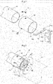
- is a perspective view of an exhaust pipe, air directors attached thereto, and an outside air mixing cylinder.
- Fig. 4
- is a side view of an exhaust pipe, air directors attached thereto, and an outside air mixing cylinder.
- Fig. 5
- is a cross-sectional view taken along line V-V in
Fig. 4 . - Fig. 6
- is a perspective view of an exhaust pipe and an outside air mixing cylinder according to alternative embodiment (a).
- Fig. 7
- is a cross-sectional view taken along line VII-VII in
Fig. 6 . - Fig. 8
- is a perspective view of an exhaust pipe and an outside air mixing cylinder according to alternative embodiment (b).
- Fig. 9
- is a cross-sectional view taken along line IX-IX in
Fig. 8 . - Fig. 10
- is a perspective view of an exhaust pipe and an outside air mixing cylinder according to alternative embodiment (c).
- Fig. 11
- is a cross-sectional view of an exhaust pipe and an outside air mixing cylinder according to alternative embodiment (d).
- The description below deals with an embodiment of the present invention with reference to drawings.
-
Fig. 1 illustrates a tractor T as a work vehicle. The tractor T includes ahood 1 at a front portion thereof, and also includes inside the hood 1 adiesel engine 2, aradiator 3, anair cleaner 4, and a diesel particulate filter (DPF)cleaning device 5 for cleaning exhaust gas. - The tractor T also includes an
exhaust pipe 6, abody frame 7, and an exhaust gas diffusing device A. The exhaust gas diffusing device A includes an outsideair mixing cylinder 11 at such a position on a side of thebody frame 7 as to receive exhaust gas from theexhaust pipe 6. The exhaust gas diffusing device A allows exhaust gas of theengine 2 cleaned by thecleaning device 5 and thereby heated to be mixed with outside air to be cooled. - The
exhaust pipe 6 is positioned at a front portion of the vehicle body and so oriented as to discharge exhaust gas in an obliquely downward direction. The outsideair mixing cylinder 11 is so oriented as to send out exhaust gas in the direction of theexhaust pipe 6. - As illustrated in
Figs. 1 to 5 , the exhaust gas diffusing device A includes an outsideair mixing cylinder 11, anintermediate cylinder 12, andair directors 13 supported by theintermediate cylinder 12. The outsideair mixing cylinder 11, theintermediate cylinder 12, and theair directors 13 are each made of, for example, a heat-resistant steel material or a stainless steel material. - The
exhaust pipe 6 has a cylindrical axis X virtually extending through the center of the pipe. The outsideair mixing cylinder 11 has its center extending coaxially with the cylindrical axis X. Theintermediate cylinder 12 is fitted around theexhaust pipe 6 and fixed thereto with use of a plurality ofbolts 15. Theintermediate cylinder 12 is provided with a pair of support frames 14 fixed thereto. Theair directors 13 are integral with one of the support frames 14 (detailed later). - With the above configuration, the
air directors 13 are at a discharge-side end portion 6E of theexhaust pipe 6. Theair directors 13 are, in other words, provided for theexhaust pipe 6 only. - As illustrated in
Fig. 5 , the outsideair mixing cylinder 11 is a cylindrical member having an inner diameter D2 larger than the outer diameter D1 of the discharge-side end portion 6E of theexhaust pipe 6. The outsideair mixing cylinder 11 is held in place by thebody frame 7 of the tractor T. Theintermediate cylinder 12 is fitted around and fixed to the discharge-side end portion 6E of theexhaust pipe 6, and holds theair directors 13 in place. - The outside
air mixing cylinder 11 may alternatively be held in place by (i) theexhaust pipe 6 with, for example, a bracket in-between or (ii) theintermediate cylinder 12 fitted around and fixed to theexhaust pipe 6. - As illustrated in
Fig. 4 , placing theexhaust pipe 6 and the outsideair mixing cylinder 11 in position results in a gap G being formed between the discharge-side end portion 6E of theexhaust pipe 6 and theupstream end portion 11E of the outsideair mixing cylinder 11. The present embodiment is arranged such that theair directors 13 are in a space inside the discharge-side end portion 6E of theexhaust pipe 6 and that theair directors 13 and the outsideair mixing cylinder 11 are so positioned as not to coincide with each other as viewed in the direction orthogonal to the direction in which exhaust gas flows (that is, in the direction in whichFig. 4 is viewed). -
Fig. 4 illustrates a case of the discharge-side end portion 6E and the corresponding end portion of theintermediate cylinder 12 coinciding with each other. In a case where, for instance, theintermediate cylinder 12 protrudes from the discharge-side end portion 6E of theexhaust pipe 6, the gap G is formed between the end portion of theintermediate cylinder 12 and theupstream end portion 11E of the outsideair mixing cylinder 11. - As illustrated in
Figs. 2 to 5 , the twoair directors 13 are, for example, press-worked to be integral with a first one of the pair of support frames 14, and are inclined in respective directions opposite to each other. The twoair directors 13 are, as illustrated inFig. 5 , in point symmetry to each other as viewed in the direction in which exhaust gas flows from the exhaust pipe 6 (that is, in the direction of the cylindrical axis X). - As illustrated in
Fig. 2 , a second one of the pair of support frames 14 has adepression 14b at a central position in its length direction (that is, in the radial direction of the intermediate cylinder 12). Engaging thefirst support frame 14 with thedepression 14b and welding thefirst support frame 14 to thesecond support frame 14 for fixation results in the pair of support frames 14 being orthogonal to each other and radially crossing theintermediate cylinder 12 as viewed in the direction of the cylindrical axis X. - The support frames 14 each include, at respective opposite ends thereof,
engagement sections 14a each in the form of a bend in the direction of the cylindrical axis X. The support frames 14 are welded and fixed to the outer surface of theintermediate cylinder 12 with theengagement sections 14a in contact with an outer edge of theintermediate cylinder 12. - The above configuration involves a gap between the radially outer end of each of the pair of
air directors 13 on thefirst support frame 14 and the inner surface of theintermediate cylinder 12. The gap receives the discharge-side end portion 6E of theexhaust pipe 6 when theintermediate cylinder 12 is fitted around theexhaust pipe 6. This allows theair directors 13 to be inside theexhaust pipe 6 as viewed in the direction orthogonal to the direction in which exhaust gas flows (that is, in the direction orthogonal to the cylindrical axis X). - The above configuration causes exhaust gas from the
exhaust pipe 6 to come into contact with the pair ofair directors 13 immediately before being discharged from the discharge-side end portion 6E of theexhaust pipe 6 and then be sent out toward the inner surface of the outsideair mixing cylinder 11 as illustrated inFig. 4 . Orienting the pair ofair directors 13 in a particular manner causes exhaust gas to, after coming into contact with theair directors 13, be sent out toward the inner surface of the outsideair mixing cylinder 11 such that the exhaust gas whirls along the inner surface of the outside air mixing cylinder 11 (that is, about the cylindrical axis X as the center). Theair directors 13 configured as above do not block the flow of exhaust gas, and allow exhaust gas to flow with a reduced pressure loss. - As described above, the gap G is between the
exhaust pipe 6 and the outsideair mixing cylinder 11. The gap G causes a negative pressure when exhaust gas flowing along the cylindrical axis X passes through the gap G. The negative pressure in turn causes outside air to enter the outsideair mixing cylinder 11 through an outside air introducing section F. Theair directors 13, which guide exhaust gas toward the inner surface of the outsideair mixing cylinder 11, promote mixing of exhaust gas with outside air introduced through the outside air introducing section F. - The above configuration allows exhaust gas to be diffused to promote mixing of exhaust gas with outside air without requiring an increased distance for exhaust gas and outside air to be mixed with each other inside the outside
air mixing cylinder 11. This makes it possible to reduce the length of the outside air mixing cylinder 11 (that is, the dimension thereof along the cylindrical axis X) and discharge cooled exhaust gas from the discharge-side end portion. The above configuration, which does not require the outsideair mixing cylinder 11 to be long as such, does not require the exhaust gas diffusing device A to be large-sized. - The outside
air mixing cylinder 11 has an outer surface in constant contact with outside air. Further, exhaust gas mixed with outside air as described above flows through the outsideair mixing cylinder 11 while in contact with its inner surface in such a manner as to whirl along the inner surface. This further promotes heat dissipation, thereby allowing suitable heat dissipation. - The present invention may alternatively be arranged as below other than the embodiment described above. Any member below that is identical in function to a particular member described for the above embodiment has the same reference sign as that particular member.
- (a) The present invention may be modified as illustrated in
Figs. 6 and 7 by (i) cutting, in an end portion of theintermediate cylinder 12, a pair of slits parallel to the cylindrical axis X, (ii) bending, toward the center of theintermediate cylinder 12, portions of theintermediate cylinder 12 that are in the vicinity of the slits such that those portions are inclined to guide exhaust gas (that is, to serve as air directors 13), and (iii) fitting theintermediate cylinder 12 around theexhaust pipe 6 to fix theintermediate cylinder 12 thereto. - This alternative embodiment (a) involves simply cutting slits in an end portion of the
intermediate cylinder 12 and bending portions thereof to formair directors 13. This eliminates the need to additionally includededicated air directors 13, and reduces the number of necessary parts. Alternative embodiment (a), similarly to the embodiment described above, causes exhaust gas to whirl along the inner surface of the outsideair mixing cylinder 11 while in contact therewith for suitable heat dissipation. - Alternatively embodiment (a) may be varied by, for instance, cutting slits in the back end of the
exhaust pipe 6 and bending portions thereof to formair directors 13. - (b) The present invention may be modified as illustrated in
Figs. 8 and 9 by (i) preparing a plate-shapedmember 21 including bent end portions as a pair ofair directors 13, (ii) inserting the plate-shapedmember 21 into theintermediate cylinder 12 such that the plate-shapedmember 21 is oriented radially, (iii) welding or otherwise fixing the plate-shapedmember 21 to theintermediate cylinder 12, and (iv) inserting theintermediate cylinder 12 into the discharge-side end portion 6E of theexhaust pipe 6 to fix theintermediate cylinder 12 thereto. - This alternative embodiment (b), which includes a plate-shaped
member 21 fixed inside theintermediate cylinder 12, allowsair directors 13 to be formed easily. Alternative embodiment (b), similarly to the embodiment described above, causes exhaust gas to whirl along the inner surface of the outsideair mixing cylinder 11 while in contact therewith for suitable heat dissipation. - (c) The present invention may be modified as illustrated in
Fig. 10 such that only one of the pair of support frames 14 for the embodiment described above includesengagement sections 14a and thatair directors 13 are formed on theother support frame 14. The pair of support frames 14 for this embodiment are welded and fixed to each other at a portion at which the pair of support frames 14 cross each other. - This alternative embodiment (c) allows size reduction of the
support frame 14 on which theair directors 13 are formed. - (d) The present invention may be modified as illustrated in
Fig. 11 by includingair directors 13 at a position inside the outsideair mixing cylinder 11 which position is upstream in the direction in which exhaust gas flows. The pair ofair directors 13 for this embodiment are formed on aninternal plate 23 welded or otherwise fixed inside the outsideair mixing cylinder 11. The pair ofair directors 13 coincide, as viewed in the direction of the cylindrical axis X, with the path into which exhaust gas is sent out from theexhaust pipe 6. - This alternative embodiment (d), similarly to the embodiment described above, causes exhaust gas to whirl along the inner surface of the outside
air mixing cylinder 11 while in contact therewith for suitable heat dissipation. - (e) The number of
air directors 13 is not limited to two, but may be three or more. Further, theair directors 13 may be disposed both for theexhaust pipe 6 and inside the outsideair mixing cylinder 11. - (f) The exhaust gas diffusing device A does not necessarily have a gap G between the discharge-
side end portion 6E of theexhaust pipe 6 and the outsideair mixing cylinder 11. The discharge-side end portion 6E of theexhaust pipe 6 and the outsideair mixing cylinder 11 may, for instance, slightly overlap with each other as viewed in the direction orthogonal to the cylindrical axis X. - (g) The
air directors 13 do not necessarily protrude from the discharge-side end portion 6E of theexhaust pipe 6. This configuration of theair directors 13 not protruding from the discharge-side end portion 6E of theexhaust pipe 6 may be combined with the configuration of the exhaust gas diffusing device A having no gap G between the discharge-side end portion 6E of theexhaust pipe 6 and the outsideair mixing cylinder 11. - The present invention is applicable to exhaust gas diffusing devices.
-
- 2
- Engine
- 6
- Exhaust pipe
- 6E
- Discharge-side end portion
- 11
- Outside air mixing cylinder
- 12
- Intermediate cylinder
- 11E
- Upstream end portion
- 13
- Air director
- 14
- Support frame
- A
- Exhaust gas diffusing device
- G
- Gap
- D1
- Outer diameter
- D2
- Inner diameter
- X
- Cylindrical axis
Claims (7)
- An exhaust gas diffusing device (A), comprising:- an outside air mixing cylinder (11) having an inner diameter (D2) larger than the outer diameter (D1) of a discharge-side end portion (6E) of an exhaust pipe (6) configured to send out exhaust gas of an engine (2) of a vehicle, the outside air mixing cylinder (11) positioned to receive the exhaust gas from the exhaust pipe (6), and configured to receive outside air to be mixed with the exhaust gas; and- at least one air director (13) disposed (i) at a position on the outside air mixing cylinder (11) which position is upstream in a direction in which the exhaust gas flows or (ii) in the exhaust pipe (6) to promote the mixing of the exhaust gas with the outside air.
- The exhaust gas diffusing device according to claim 1, wherein the at least one air director (13) is disposed only in the exhaust pipe (6).
- The exhaust gas diffusing device according to claim 2, wherein the at least one air director (13) is disposed at the discharge-side end portion (6E) of the exhaust pipe (6).
- The exhaust gas diffusing device according to claim 2 or 3, wherein the exhaust gas diffusing device (A) has a gap (G) between the discharge-side end portion (6E) and an end portion (11E) of the outside air mixing cylinder (11) which end portion (11E) is upstream in the direction in which the exhaust gas flows.
- The exhaust gas diffusing device according to any one of claims 2 to 4, wherein the at least one air director (13) does not coincide with the outside air mixing cylinder (11) as viewed in a direction orthogonal to the direction in which the exhaust gas flows.
- The exhaust gas diffusing device according to any one of claims 1 to 5, wherein the at least one air director (13) is oriented to guide the exhaust gas in such a direction that the exhaust gas comes into contact with an inner surface of the outside air mixing cylinder (11).
- The exhaust gas diffusing device according to any one of claims 1 to 6, wherein the at least one air director (13) includes a plurality of air directors (13) arranged in point symmetry to each other as viewed in the direction in which the exhaust gas flows.
Applications Claiming Priority (1)
| Application Number | Priority Date | Filing Date | Title |
|---|---|---|---|
| JP2020216956A JP7507681B2 (en) | 2020-12-25 | 2020-12-25 | Exhaust gas diffusion device |
Publications (2)
| Publication Number | Publication Date |
|---|---|
| EP4019750A1 true EP4019750A1 (en) | 2022-06-29 |
| EP4019750B1 EP4019750B1 (en) | 2024-09-25 |
Family
ID=78821093
Family Applications (1)
| Application Number | Title | Priority Date | Filing Date |
|---|---|---|---|
| EP21212189.1A Active EP4019750B1 (en) | 2020-12-25 | 2021-12-03 | Exhaust gas diffusing device |
Country Status (3)
| Country | Link |
|---|---|
| US (1) | US20220203314A1 (en) |
| EP (1) | EP4019750B1 (en) |
| JP (1) | JP7507681B2 (en) |
Families Citing this family (3)
| Publication number | Priority date | Publication date | Assignee | Title |
|---|---|---|---|---|
| JP7612549B2 (en) | 2021-09-30 | 2025-01-14 | 株式会社クボタ | Work vehicle |
| US11732626B2 (en) * | 2021-12-28 | 2023-08-22 | Honda Motor Co., Ltd. | Mixer and mobile body |
| EP4361410B1 (en) * | 2022-10-26 | 2025-02-12 | Kubota Corporation | Work vehicle |
Citations (10)
| Publication number | Priority date | Publication date | Assignee | Title |
|---|---|---|---|---|
| JPS52152911U (en) | 1976-05-18 | 1977-11-19 | ||
| JPS52152911A (en) | 1976-06-14 | 1977-12-19 | Leitz Ernst Gmbh | Optical flint glass of small density |
| JPS54108817U (en) | 1978-01-18 | 1979-07-31 | ||
| US4331213A (en) * | 1980-01-28 | 1982-05-25 | Mitsuko Leith | Automobile exhaust control system |
| JPH02108817A (en) | 1988-10-19 | 1990-04-20 | Mazda Motor Corp | Air intake device for v type engine |
| FR2689577A1 (en) * | 1992-04-02 | 1993-10-08 | Pidell Lucien | Fluid flow booster e.g. for i.c. engine intake or exhaust - consists of convergent pipe set at distance from end of intake pipe to create supplementary flow |
| US20050205355A1 (en) * | 2004-03-17 | 2005-09-22 | Shin-Seng Lin | Tailpipe of automotive vehicle |
| US20100000205A1 (en) * | 2008-07-01 | 2010-01-07 | General Motors Global Technology Operations, Inc. | Apparatus and method for cooling an exhaust gas |
| KR20140096709A (en) * | 2013-01-29 | 2014-08-06 | 김기훈 | Exhause velocity increase device of automobile |
| GB2513187A (en) * | 2013-04-19 | 2014-10-22 | Leyland Trucks Ltd | Diffuser assembly |
Family Cites Families (15)
| Publication number | Priority date | Publication date | Assignee | Title |
|---|---|---|---|---|
| US6796296B2 (en) | 2002-06-05 | 2004-09-28 | Jay S. Kim | Fluid swirling device for an internal combustion engine |
| US5058703A (en) * | 1987-11-23 | 1991-10-22 | United Technologies Corporation | Automotive exhaust noise attenuator |
| JP3136130B2 (en) | 1998-06-23 | 2001-02-19 | 川崎重工業株式会社 | Small general-purpose engine muffler |
| US20050061571A1 (en) * | 2003-09-19 | 2005-03-24 | Terrance Chen | Tail pipe ornament & method |
| US20060092621A1 (en) * | 2004-10-29 | 2006-05-04 | Lai Marcos Y S | Tailpipe decoration |
| US20070144158A1 (en) * | 2005-12-22 | 2007-06-28 | Girard James W | Exhaust dispersion device |
| EP2162603A4 (en) * | 2007-06-15 | 2012-03-07 | Choon Nam Son | Apparatus for removing exhaust gas pressure and preventing backflow of exhaust gas |
| EP2262982B1 (en) * | 2008-04-18 | 2016-08-17 | Tenneco Automotive Operating Company Inc. | Tail pipe exhaust cooling device |
| JP2010071240A (en) * | 2008-09-19 | 2010-04-02 | Tokyo Roki Co Ltd | Exhaust gas purifying device for internal combustion engine, and swirl flow generating device |
| US8549850B2 (en) * | 2008-10-31 | 2013-10-08 | Cummins Filtration Ip, Inc. | Exhaust gas aspirator |
| JP5478920B2 (en) * | 2009-03-23 | 2014-04-23 | 株式会社マツ・ショウ | Spiral tail for energy-saving exhaust muffler and usage of spiral tail |
| US20140305109A1 (en) * | 2010-10-15 | 2014-10-16 | Volvo Lastvagnar Ab | Exhaust pipe arrangement for discharging exhaust from a combustion engine |
| JP5865197B2 (en) | 2012-07-03 | 2016-02-17 | 株式会社クボタ | Exhaust pipe |
| DE102014009052B4 (en) * | 2014-06-18 | 2025-09-04 | Man Truck & Bus Se | Cab-mounted exhaust pipe for a vehicle |
| JP2019214964A (en) | 2018-06-13 | 2019-12-19 | いすゞ自動車株式会社 | Tail pipe structure of internal combustion engine |
-
2020
- 2020-12-25 JP JP2020216956A patent/JP7507681B2/en active Active
-
2021
- 2021-12-02 US US17/540,273 patent/US20220203314A1/en not_active Abandoned
- 2021-12-03 EP EP21212189.1A patent/EP4019750B1/en active Active
Patent Citations (10)
| Publication number | Priority date | Publication date | Assignee | Title |
|---|---|---|---|---|
| JPS52152911U (en) | 1976-05-18 | 1977-11-19 | ||
| JPS52152911A (en) | 1976-06-14 | 1977-12-19 | Leitz Ernst Gmbh | Optical flint glass of small density |
| JPS54108817U (en) | 1978-01-18 | 1979-07-31 | ||
| US4331213A (en) * | 1980-01-28 | 1982-05-25 | Mitsuko Leith | Automobile exhaust control system |
| JPH02108817A (en) | 1988-10-19 | 1990-04-20 | Mazda Motor Corp | Air intake device for v type engine |
| FR2689577A1 (en) * | 1992-04-02 | 1993-10-08 | Pidell Lucien | Fluid flow booster e.g. for i.c. engine intake or exhaust - consists of convergent pipe set at distance from end of intake pipe to create supplementary flow |
| US20050205355A1 (en) * | 2004-03-17 | 2005-09-22 | Shin-Seng Lin | Tailpipe of automotive vehicle |
| US20100000205A1 (en) * | 2008-07-01 | 2010-01-07 | General Motors Global Technology Operations, Inc. | Apparatus and method for cooling an exhaust gas |
| KR20140096709A (en) * | 2013-01-29 | 2014-08-06 | 김기훈 | Exhause velocity increase device of automobile |
| GB2513187A (en) * | 2013-04-19 | 2014-10-22 | Leyland Trucks Ltd | Diffuser assembly |
Also Published As
| Publication number | Publication date |
|---|---|
| JP7507681B2 (en) | 2024-06-28 |
| EP4019750B1 (en) | 2024-09-25 |
| US20220203314A1 (en) | 2022-06-30 |
| JP2022102298A (en) | 2022-07-07 |
Similar Documents
| Publication | Publication Date | Title |
|---|---|---|
| US20220203314A1 (en) | Exhaust gas diffusing device | |
| US9289724B2 (en) | Flow reversing exhaust gas mixer | |
| KR101327882B1 (en) | Reducing agent aqueous solution mixing device and exhaust gas post-treatment device | |
| US6840039B2 (en) | Exhaust manifold for improvement of purification efficiency and lifetime of a catalytic converter | |
| US20160376969A1 (en) | Cantilevered Flow Distributing Apparatus | |
| BR112017026777B1 (en) | EXHAUST TREATMENT DEVICE | |
| CN111603936B (en) | System and method for mixing exhaust gas and reductant | |
| CN212054866U (en) | Tail gas aftertreatment system | |
| CN101341326A (en) | exhaust diffuser | |
| US8109083B2 (en) | Aspirator support structure | |
| CN105934567B (en) | Axial atomization module | |
| CN111727083A (en) | Compact exhaust gas mixing system | |
| CN104619966B (en) | Engine exhaust system with catalytic converter | |
| US10480372B2 (en) | Mixer in an exhaust gas system | |
| JPH10110612A (en) | Exhauster | |
| CN106460621A (en) | Exhaust gas stirring device | |
| CN113137299A (en) | Gas/gas mixer for introducing gas into the exhaust gas flow of an internal combustion engine | |
| KR101780341B1 (en) | Axial flow atomization module | |
| EP4390075A1 (en) | Exhaust gas aftertreatment mixer | |
| JP2012082742A (en) | Exhaust emission control device | |
| US20220333521A1 (en) | Exhaust gas/reactant mixing device | |
| JP7556829B2 (en) | Exhaust Gas Purification Device | |
| JP7791052B2 (en) | Exhaust gas purification equipment | |
| CN116888349A (en) | Exhaust after-treatment system | |
| US20260125998A1 (en) | Exhaust treatment device |
Legal Events
| Date | Code | Title | Description |
|---|---|---|---|
| PUAI | Public reference made under article 153(3) epc to a published international application that has entered the european phase |
Free format text: ORIGINAL CODE: 0009012 |
|
| STAA | Information on the status of an ep patent application or granted ep patent |
Free format text: STATUS: THE APPLICATION HAS BEEN PUBLISHED |
|
| AK | Designated contracting states |
Kind code of ref document: A1 Designated state(s): AL AT BE BG CH CY CZ DE DK EE ES FI FR GB GR HR HU IE IS IT LI LT LU LV MC MK MT NL NO PL PT RO RS SE SI SK SM TR |
|
| STAA | Information on the status of an ep patent application or granted ep patent |
Free format text: STATUS: REQUEST FOR EXAMINATION WAS MADE |
|
| 17P | Request for examination filed |
Effective date: 20221228 |
|
| RBV | Designated contracting states (corrected) |
Designated state(s): AL AT BE BG CH CY CZ DE DK EE ES FI FR GB GR HR HU IE IS IT LI LT LU LV MC MK MT NL NO PL PT RO RS SE SI SK SM TR |
|
| GRAP | Despatch of communication of intention to grant a patent |
Free format text: ORIGINAL CODE: EPIDOSNIGR1 |
|
| STAA | Information on the status of an ep patent application or granted ep patent |
Free format text: STATUS: GRANT OF PATENT IS INTENDED |
|
| INTG | Intention to grant announced |
Effective date: 20240417 |
|
| GRAS | Grant fee paid |
Free format text: ORIGINAL CODE: EPIDOSNIGR3 |
|
| P01 | Opt-out of the competence of the unified patent court (upc) registered |
Free format text: CASE NUMBER: APP_40364/2024 Effective date: 20240708 |
|
| GRAA | (expected) grant |
Free format text: ORIGINAL CODE: 0009210 |
|
| STAA | Information on the status of an ep patent application or granted ep patent |
Free format text: STATUS: THE PATENT HAS BEEN GRANTED |
|
| AK | Designated contracting states |
Kind code of ref document: B1 Designated state(s): AL AT BE BG CH CY CZ DE DK EE ES FI FR GB GR HR HU IE IS IT LI LT LU LV MC MK MT NL NO PL PT RO RS SE SI SK SM TR |
|
| REG | Reference to a national code |
Ref country code: GB Ref legal event code: FG4D |
|
| REG | Reference to a national code |
Ref country code: CH Ref legal event code: EP |
|
| REG | Reference to a national code |
Ref country code: DE Ref legal event code: R096 Ref document number: 602021019251 Country of ref document: DE |
|
| REG | Reference to a national code |
Ref country code: IE Ref legal event code: FG4D |
|
| REG | Reference to a national code |
Ref country code: LT Ref legal event code: MG9D |
|
| PG25 | Lapsed in a contracting state [announced via postgrant information from national office to epo] |
Ref country code: NO Free format text: LAPSE BECAUSE OF FAILURE TO SUBMIT A TRANSLATION OF THE DESCRIPTION OR TO PAY THE FEE WITHIN THE PRESCRIBED TIME-LIMIT Effective date: 20241225 |
|
| PG25 | Lapsed in a contracting state [announced via postgrant information from national office to epo] |
Ref country code: GR Free format text: LAPSE BECAUSE OF FAILURE TO SUBMIT A TRANSLATION OF THE DESCRIPTION OR TO PAY THE FEE WITHIN THE PRESCRIBED TIME-LIMIT Effective date: 20241226 Ref country code: FI Free format text: LAPSE BECAUSE OF FAILURE TO SUBMIT A TRANSLATION OF THE DESCRIPTION OR TO PAY THE FEE WITHIN THE PRESCRIBED TIME-LIMIT Effective date: 20240925 |
|
| PG25 | Lapsed in a contracting state [announced via postgrant information from national office to epo] |
Ref country code: BG Free format text: LAPSE BECAUSE OF FAILURE TO SUBMIT A TRANSLATION OF THE DESCRIPTION OR TO PAY THE FEE WITHIN THE PRESCRIBED TIME-LIMIT Effective date: 20240925 |
|
| PG25 | Lapsed in a contracting state [announced via postgrant information from national office to epo] |
Ref country code: LV Free format text: LAPSE BECAUSE OF FAILURE TO SUBMIT A TRANSLATION OF THE DESCRIPTION OR TO PAY THE FEE WITHIN THE PRESCRIBED TIME-LIMIT Effective date: 20240925 |
|
| PG25 | Lapsed in a contracting state [announced via postgrant information from national office to epo] |
Ref country code: RS Free format text: LAPSE BECAUSE OF FAILURE TO SUBMIT A TRANSLATION OF THE DESCRIPTION OR TO PAY THE FEE WITHIN THE PRESCRIBED TIME-LIMIT Effective date: 20241225 |
|
| REG | Reference to a national code |
Ref country code: NL Ref legal event code: MP Effective date: 20240925 |
|
| PG25 | Lapsed in a contracting state [announced via postgrant information from national office to epo] |
Ref country code: RS Free format text: LAPSE BECAUSE OF FAILURE TO SUBMIT A TRANSLATION OF THE DESCRIPTION OR TO PAY THE FEE WITHIN THE PRESCRIBED TIME-LIMIT Effective date: 20241225 Ref country code: NO Free format text: LAPSE BECAUSE OF FAILURE TO SUBMIT A TRANSLATION OF THE DESCRIPTION OR TO PAY THE FEE WITHIN THE PRESCRIBED TIME-LIMIT Effective date: 20241225 Ref country code: LV Free format text: LAPSE BECAUSE OF FAILURE TO SUBMIT A TRANSLATION OF THE DESCRIPTION OR TO PAY THE FEE WITHIN THE PRESCRIBED TIME-LIMIT Effective date: 20240925 Ref country code: GR Free format text: LAPSE BECAUSE OF FAILURE TO SUBMIT A TRANSLATION OF THE DESCRIPTION OR TO PAY THE FEE WITHIN THE PRESCRIBED TIME-LIMIT Effective date: 20241226 Ref country code: FI Free format text: LAPSE BECAUSE OF FAILURE TO SUBMIT A TRANSLATION OF THE DESCRIPTION OR TO PAY THE FEE WITHIN THE PRESCRIBED TIME-LIMIT Effective date: 20240925 Ref country code: BG Free format text: LAPSE BECAUSE OF FAILURE TO SUBMIT A TRANSLATION OF THE DESCRIPTION OR TO PAY THE FEE WITHIN THE PRESCRIBED TIME-LIMIT Effective date: 20240925 |
|
| REG | Reference to a national code |
Ref country code: AT Ref legal event code: MK05 Ref document number: 1726799 Country of ref document: AT Kind code of ref document: T Effective date: 20240925 |
|
| PG25 | Lapsed in a contracting state [announced via postgrant information from national office to epo] |
Ref country code: NL Free format text: LAPSE BECAUSE OF FAILURE TO SUBMIT A TRANSLATION OF THE DESCRIPTION OR TO PAY THE FEE WITHIN THE PRESCRIBED TIME-LIMIT Effective date: 20240925 |
|
| PG25 | Lapsed in a contracting state [announced via postgrant information from national office to epo] |
Ref country code: PT Free format text: LAPSE BECAUSE OF FAILURE TO SUBMIT A TRANSLATION OF THE DESCRIPTION OR TO PAY THE FEE WITHIN THE PRESCRIBED TIME-LIMIT Effective date: 20250127 Ref country code: IS Free format text: LAPSE BECAUSE OF FAILURE TO SUBMIT A TRANSLATION OF THE DESCRIPTION OR TO PAY THE FEE WITHIN THE PRESCRIBED TIME-LIMIT Effective date: 20250125 |
|
| PG25 | Lapsed in a contracting state [announced via postgrant information from national office to epo] |
Ref country code: RO Free format text: LAPSE BECAUSE OF FAILURE TO SUBMIT A TRANSLATION OF THE DESCRIPTION OR TO PAY THE FEE WITHIN THE PRESCRIBED TIME-LIMIT Effective date: 20240925 Ref country code: SM Free format text: LAPSE BECAUSE OF FAILURE TO SUBMIT A TRANSLATION OF THE DESCRIPTION OR TO PAY THE FEE WITHIN THE PRESCRIBED TIME-LIMIT Effective date: 20240925 |
|
| PG25 | Lapsed in a contracting state [announced via postgrant information from national office to epo] |
Ref country code: ES Free format text: LAPSE BECAUSE OF FAILURE TO SUBMIT A TRANSLATION OF THE DESCRIPTION OR TO PAY THE FEE WITHIN THE PRESCRIBED TIME-LIMIT Effective date: 20240925 |
|
| PG25 | Lapsed in a contracting state [announced via postgrant information from national office to epo] |
Ref country code: EE Free format text: LAPSE BECAUSE OF FAILURE TO SUBMIT A TRANSLATION OF THE DESCRIPTION OR TO PAY THE FEE WITHIN THE PRESCRIBED TIME-LIMIT Effective date: 20240925 Ref country code: AT Free format text: LAPSE BECAUSE OF FAILURE TO SUBMIT A TRANSLATION OF THE DESCRIPTION OR TO PAY THE FEE WITHIN THE PRESCRIBED TIME-LIMIT Effective date: 20240925 |
|
| PG25 | Lapsed in a contracting state [announced via postgrant information from national office to epo] |
Ref country code: PL Free format text: LAPSE BECAUSE OF FAILURE TO SUBMIT A TRANSLATION OF THE DESCRIPTION OR TO PAY THE FEE WITHIN THE PRESCRIBED TIME-LIMIT Effective date: 20240925 Ref country code: CZ Free format text: LAPSE BECAUSE OF FAILURE TO SUBMIT A TRANSLATION OF THE DESCRIPTION OR TO PAY THE FEE WITHIN THE PRESCRIBED TIME-LIMIT Effective date: 20240925 |
|
| PG25 | Lapsed in a contracting state [announced via postgrant information from national office to epo] |
Ref country code: IT Free format text: LAPSE BECAUSE OF FAILURE TO SUBMIT A TRANSLATION OF THE DESCRIPTION OR TO PAY THE FEE WITHIN THE PRESCRIBED TIME-LIMIT Effective date: 20240925 Ref country code: SK Free format text: LAPSE BECAUSE OF FAILURE TO SUBMIT A TRANSLATION OF THE DESCRIPTION OR TO PAY THE FEE WITHIN THE PRESCRIBED TIME-LIMIT Effective date: 20240925 |
|
| REG | Reference to a national code |
Ref country code: DE Ref legal event code: R097 Ref document number: 602021019251 Country of ref document: DE |
|
| PG25 | Lapsed in a contracting state [announced via postgrant information from national office to epo] |
Ref country code: MC Free format text: LAPSE BECAUSE OF FAILURE TO SUBMIT A TRANSLATION OF THE DESCRIPTION OR TO PAY THE FEE WITHIN THE PRESCRIBED TIME-LIMIT Effective date: 20240925 |
|
| PG25 | Lapsed in a contracting state [announced via postgrant information from national office to epo] |
Ref country code: DK Free format text: LAPSE BECAUSE OF FAILURE TO SUBMIT A TRANSLATION OF THE DESCRIPTION OR TO PAY THE FEE WITHIN THE PRESCRIBED TIME-LIMIT Effective date: 20240925 |
|
| REG | Reference to a national code |
Ref country code: CH Ref legal event code: PL |
|
| PLBE | No opposition filed within time limit |
Free format text: ORIGINAL CODE: 0009261 |
|
| STAA | Information on the status of an ep patent application or granted ep patent |
Free format text: STATUS: NO OPPOSITION FILED WITHIN TIME LIMIT |
|
| PG25 | Lapsed in a contracting state [announced via postgrant information from national office to epo] |
Ref country code: LU Free format text: LAPSE BECAUSE OF NON-PAYMENT OF DUE FEES Effective date: 20241203 |
|
| 26N | No opposition filed |
Effective date: 20250626 |
|
| PG25 | Lapsed in a contracting state [announced via postgrant information from national office to epo] |
Ref country code: SE Free format text: LAPSE BECAUSE OF FAILURE TO SUBMIT A TRANSLATION OF THE DESCRIPTION OR TO PAY THE FEE WITHIN THE PRESCRIBED TIME-LIMIT Effective date: 20240925 |
|
| REG | Reference to a national code |
Ref country code: BE Ref legal event code: MM Effective date: 20241231 |
|
| PG25 | Lapsed in a contracting state [announced via postgrant information from national office to epo] |
Ref country code: BE Free format text: LAPSE BECAUSE OF NON-PAYMENT OF DUE FEES Effective date: 20241231 |
|
| PG25 | Lapsed in a contracting state [announced via postgrant information from national office to epo] |
Ref country code: CH Free format text: LAPSE BECAUSE OF NON-PAYMENT OF DUE FEES Effective date: 20241231 |
|
| PG25 | Lapsed in a contracting state [announced via postgrant information from national office to epo] |
Ref country code: IE Free format text: LAPSE BECAUSE OF NON-PAYMENT OF DUE FEES Effective date: 20241203 |
|
| PGFP | Annual fee paid to national office [announced via postgrant information from national office to epo] |
Ref country code: DE Payment date: 20251028 Year of fee payment: 5 |
|
| PG25 | Lapsed in a contracting state [announced via postgrant information from national office to epo] |
Ref country code: HR Free format text: LAPSE BECAUSE OF FAILURE TO SUBMIT A TRANSLATION OF THE DESCRIPTION OR TO PAY THE FEE WITHIN THE PRESCRIBED TIME-LIMIT Effective date: 20240925 |
|
| PGFP | Annual fee paid to national office [announced via postgrant information from national office to epo] |
Ref country code: FR Payment date: 20251110 Year of fee payment: 5 |
|
| PG25 | Lapsed in a contracting state [announced via postgrant information from national office to epo] |
Ref country code: CY Free format text: LAPSE BECAUSE OF FAILURE TO SUBMIT A TRANSLATION OF THE DESCRIPTION OR TO PAY THE FEE WITHIN THE PRESCRIBED TIME-LIMIT; INVALID AB INITIO Effective date: 20211203 |