EP4019740A1 - Rotor assembly having a balancing ring with an anti-rotation spacer - Google Patents
Rotor assembly having a balancing ring with an anti-rotation spacer Download PDFInfo
- Publication number
- EP4019740A1 EP4019740A1 EP21213181.7A EP21213181A EP4019740A1 EP 4019740 A1 EP4019740 A1 EP 4019740A1 EP 21213181 A EP21213181 A EP 21213181A EP 4019740 A1 EP4019740 A1 EP 4019740A1
- Authority
- EP
- European Patent Office
- Prior art keywords
- rotating
- spacer
- rotating component
- circlip
- circumferential
- Prior art date
- Legal status (The legal status is an assumption and is not a legal conclusion. Google has not performed a legal analysis and makes no representation as to the accuracy of the status listed.)
- Granted
Links
Images




Classifications
-
- F—MECHANICAL ENGINEERING; LIGHTING; HEATING; WEAPONS; BLASTING
- F01—MACHINES OR ENGINES IN GENERAL; ENGINE PLANTS IN GENERAL; STEAM ENGINES
- F01D—NON-POSITIVE DISPLACEMENT MACHINES OR ENGINES, e.g. STEAM TURBINES
- F01D5/00—Blades; Blade-carrying members; Heating, heat-insulating, cooling or antivibration means on the blades or the members
- F01D5/02—Blade-carrying members, e.g. rotors
- F01D5/027—Arrangements for balancing
-
- F—MECHANICAL ENGINEERING; LIGHTING; HEATING; WEAPONS; BLASTING
- F04—POSITIVE - DISPLACEMENT MACHINES FOR LIQUIDS; PUMPS FOR LIQUIDS OR ELASTIC FLUIDS
- F04D—NON-POSITIVE-DISPLACEMENT PUMPS
- F04D19/00—Axial-flow pumps
- F04D19/02—Multi-stage pumps
-
- F—MECHANICAL ENGINEERING; LIGHTING; HEATING; WEAPONS; BLASTING
- F04—POSITIVE - DISPLACEMENT MACHINES FOR LIQUIDS; PUMPS FOR LIQUIDS OR ELASTIC FLUIDS
- F04D—NON-POSITIVE-DISPLACEMENT PUMPS
- F04D29/00—Details, component parts, or accessories
- F04D29/05—Shafts or bearings, or assemblies thereof, specially adapted for elastic fluid pumps
- F04D29/056—Bearings
-
- F—MECHANICAL ENGINEERING; LIGHTING; HEATING; WEAPONS; BLASTING
- F04—POSITIVE - DISPLACEMENT MACHINES FOR LIQUIDS; PUMPS FOR LIQUIDS OR ELASTIC FLUIDS
- F04D—NON-POSITIVE-DISPLACEMENT PUMPS
- F04D29/00—Details, component parts, or accessories
- F04D29/08—Sealings
- F04D29/10—Shaft sealings
- F04D29/102—Shaft sealings especially adapted for elastic fluid pumps
-
- F—MECHANICAL ENGINEERING; LIGHTING; HEATING; WEAPONS; BLASTING
- F04—POSITIVE - DISPLACEMENT MACHINES FOR LIQUIDS; PUMPS FOR LIQUIDS OR ELASTIC FLUIDS
- F04D—NON-POSITIVE-DISPLACEMENT PUMPS
- F04D29/00—Details, component parts, or accessories
- F04D29/26—Rotors specially for elastic fluids
- F04D29/266—Rotors specially for elastic fluids mounting compressor rotors on shafts
-
- F—MECHANICAL ENGINEERING; LIGHTING; HEATING; WEAPONS; BLASTING
- F04—POSITIVE - DISPLACEMENT MACHINES FOR LIQUIDS; PUMPS FOR LIQUIDS OR ELASTIC FLUIDS
- F04D—NON-POSITIVE-DISPLACEMENT PUMPS
- F04D29/00—Details, component parts, or accessories
- F04D29/60—Mounting; Assembling; Disassembling
- F04D29/64—Mounting; Assembling; Disassembling of axial pumps
- F04D29/644—Mounting; Assembling; Disassembling of axial pumps especially adapted for elastic fluid pumps
-
- F—MECHANICAL ENGINEERING; LIGHTING; HEATING; WEAPONS; BLASTING
- F04—POSITIVE - DISPLACEMENT MACHINES FOR LIQUIDS; PUMPS FOR LIQUIDS OR ELASTIC FLUIDS
- F04D—NON-POSITIVE-DISPLACEMENT PUMPS
- F04D29/00—Details, component parts, or accessories
- F04D29/66—Combating cavitation, whirls, noise, vibration or the like; Balancing
- F04D29/661—Combating cavitation, whirls, noise, vibration or the like; Balancing especially adapted for elastic fluid pumps
- F04D29/662—Balancing of rotors
-
- F—MECHANICAL ENGINEERING; LIGHTING; HEATING; WEAPONS; BLASTING
- F05—INDEXING SCHEMES RELATING TO ENGINES OR PUMPS IN VARIOUS SUBCLASSES OF CLASSES F01-F04
- F05D—INDEXING SCHEME FOR ASPECTS RELATING TO NON-POSITIVE-DISPLACEMENT MACHINES OR ENGINES, GAS-TURBINES OR JET-PROPULSION PLANTS
- F05D2230/00—Manufacture
- F05D2230/60—Assembly methods
- F05D2230/64—Assembly methods using positioning or alignment devices for aligning or centring, e.g. pins
- F05D2230/644—Assembly methods using positioning or alignment devices for aligning or centring, e.g. pins for adjusting the position or the alignment, e.g. wedges or eccenters
-
- F—MECHANICAL ENGINEERING; LIGHTING; HEATING; WEAPONS; BLASTING
- F05—INDEXING SCHEMES RELATING TO ENGINES OR PUMPS IN VARIOUS SUBCLASSES OF CLASSES F01-F04
- F05D—INDEXING SCHEME FOR ASPECTS RELATING TO NON-POSITIVE-DISPLACEMENT MACHINES OR ENGINES, GAS-TURBINES OR JET-PROPULSION PLANTS
- F05D2250/00—Geometry
- F05D2250/30—Arrangement of components
- F05D2250/37—Arrangement of components circumferential
-
- F—MECHANICAL ENGINEERING; LIGHTING; HEATING; WEAPONS; BLASTING
- F05—INDEXING SCHEMES RELATING TO ENGINES OR PUMPS IN VARIOUS SUBCLASSES OF CLASSES F01-F04
- F05D—INDEXING SCHEME FOR ASPECTS RELATING TO NON-POSITIVE-DISPLACEMENT MACHINES OR ENGINES, GAS-TURBINES OR JET-PROPULSION PLANTS
- F05D2260/00—Function
- F05D2260/15—Load balancing
-
- F—MECHANICAL ENGINEERING; LIGHTING; HEATING; WEAPONS; BLASTING
- F05—INDEXING SCHEMES RELATING TO ENGINES OR PUMPS IN VARIOUS SUBCLASSES OF CLASSES F01-F04
- F05D—INDEXING SCHEME FOR ASPECTS RELATING TO NON-POSITIVE-DISPLACEMENT MACHINES OR ENGINES, GAS-TURBINES OR JET-PROPULSION PLANTS
- F05D2260/00—Function
- F05D2260/30—Retaining components in desired mutual position
- F05D2260/36—Retaining components in desired mutual position by a form fit connection, e.g. by interlocking
-
- F—MECHANICAL ENGINEERING; LIGHTING; HEATING; WEAPONS; BLASTING
- F05—INDEXING SCHEMES RELATING TO ENGINES OR PUMPS IN VARIOUS SUBCLASSES OF CLASSES F01-F04
- F05D—INDEXING SCHEME FOR ASPECTS RELATING TO NON-POSITIVE-DISPLACEMENT MACHINES OR ENGINES, GAS-TURBINES OR JET-PROPULSION PLANTS
- F05D2260/00—Function
- F05D2260/96—Preventing, counteracting or reducing vibration or noise
Definitions
- the application relates generally to rotating structures and, more particularly, to a balancing ring mounting arrangement.
- Turbo machinery rotating structures are balanced to minimize residual vibration and resulting stresses.
- a known balancing technique is to add counterweights at predetermined locations to generate an opposite unbalance cancelling the rotating structure initial unbalance.
- Other techniques include rotation of balancing rings on the rotating structure to cancel the rotating structure initial unbalance.
- One of the challenges in using such balancing rings is to lock their orientation to secure the unbalance correction once the rings have been properly circumferentially oriented on the rotating structure.
- a rotating assembly for a gas turbine engine comprising: a first rotating component mounted for rotation about an axis; at least one balancing ring mounted to the first rotating component and clocked at a circumferential position about the axis to counteract a rotating unbalance of the first rotating component; and a spacer axially abutted against the first rotating component to set an axial position of the first rotating component relative to a second rotating component of the rotating assembly, the spacer locking the at least one balancing ring against rotation relative to the first rotating component.
- At least one balancing ring is mounted to a rotating component of a rotary stack and is locked against rotation in a desired circumferential position relative to the rotating component by a spacer used to adjust an axial distance between the rotating component and another component of the rotary stack.
- the dual use spacer has anti-rotation features for mating engagement with corresponding anti-rotation features on the balancing ring.
- a spacer which combines two functions into a single component: 1) providing axial adjustment between two components of a rotating assembly and 2) providing a circumferential locking action for balancing rings used to balance a component of a rotating assembly of a gas turbine engine.
- the spacer and the at least one balancing ring have a circumferential interface with cooperating anti-rotation male/female portions.
- a rotating assembly of a gas turbine engine comprising: a first rotating component mounted to a shaft for rotation therewith about an axis; at least one circlip mounted to the first rotating component, the at least one circlip having a center of mass offset from the axis, the at least one circlip being adjustably rotatable relative to the first component about the axis to a circumferential position in which the at least one circlip counters a rotating unbalance of the first rotating component; and a spacer axially clamped between the first rotating component and a second rotating component of the rotating assembly, the spacer having scallops circumferentially spaced apart along a circumferential surface thereof around the axis, the scallops engageable with lugs projecting from the at least one circlip for locking the at least one circlip against rotation relative to the first component.
- the at least one circlip may have a smooth circumferential interface with the first rotating component to provide for an infinite number of possible angular orientations of the at least one circlip relative to the first rotating component.
- the at least one circlip may have a smooth outer diameter surface, and the lugs may extend from an inner diameter surface of the at least one circlip.
- the circumferential surface of the spacer with the scallops may be provided on an outer diameter of the spacer.
- the at last one circlip may comprise first and second circlips, the first circlip may have a smaller diameter than the second circlip, and the scallops may include first and second arrays of scallops circumferentially distributed on two different diameters of the spacer for engagement with the first and second circlips, respectively.
- the first and second rotating components may be press fit to the shaft, and the spacer may be mounted to the shaft with a loose fit.
- a method of balancing a first rotating component of a stack of rotating components of a gas turbine engine, the first rotating component mounted for rotation about an axis of rotation comprising: mounting at least one circlip in a corresponding seat on the first rotating component, the at least one circlip having a center of mass offset from the axis of rotation; adjusting an angular orientation of the at least one circlip relative to the first rotating component, including rotating the at least one circlip about the axis of rotation to a circumferential position in which the at least one circlip counters a rotating unbalance of the first rotating component; and locking the at least one circlip against rotation relative to the first rotating component using a spacer axially clamped between the first rotating component and a second rotating component of the stack of rotating component.
- Fig. 1 illustrates a gas turbine engine 10 of a type preferably provided for use in subsonic flight, generally comprising in serial flow communication a fan 12 through which ambient air is propelled, a compressor section 14 for pressurizing the air, a combustor 16 in which the compressed air is mixed with fuel and ignited for generating an annular stream of hot combustion gases, and a turbine section 18 for extracting energy from the combustion gases.
- the exemplified engine 10 is a multi-spool engine including multiple rotating assemblies (e.g. a high pressure spool and a low pressure spool) mounted for rotation about an axis 11 (e.g. the engine centerline).
- each rotating assembly may comprise a stack of rotating components axially clamped together on a shaft.
- each stack may comprise one or more compressor rotors, one or more turbine rotors, front and rear seal runners, one or more bearings, one or more oil scoops, and one or more spacers secured together on a shaft for rotation therewith.
- the rotating assembly may consist of a transmission shaft with its associated gears and spacers.
- a rotating assembly could include a gear mounted to a transmission shaft with a spacer on the shaft to adjust a position of the gear relative to its pinion.
- the above examples of rotating assemblies are not intended to constitute an exhaustive list of all rotating assemblies found in gas turbine engines.
- spacer is herein intended to generally refer to a purposely designed part introduced in a rotary stack to adjust the distance between two rotating components taking account of the stacked parts actual axial length.
- spacers may be used to adjust the axial distance between the compressor and the turbine with respect to the stators to maximize engine performance.
- spacers can also be used to adjust the position of a gear in relation to its pinion.
- Optimal spacer length is computed by measuring relevant dimensions in the rotary stack. The optimal computed spacer length is used to either grind an oversized part or is used to select a specific spacer length among pre-cut parts.
- Fig. 2 is a simplified schematic view of an exemplary rotating assembly 20 comprising a number of rotating components 22a-22h axially clamped together on a rotating shaft 24 for rotation about axis 11 of the gas turbine engine 10.
- the rotating assembly 20 needs to be balanced.
- a rotating unbalance is known as an uneven distribution of mass around an axis of rotation.
- a rotating component is said to be out of balance when its center of mass (inertia axis) is out of alignment with the center of rotation (geometric axis). Unbalance may cause a moment which gives the rotating component a wobbling movement characteristic of vibration of rotating structures.
- such a rotating unbalance may be corrected through the addition of dedicated balancing rings to an unbalance rotating component of a rotating assembly and by adjusting the relative angle between the balancing rings depending on the unbalance to be corrected.
- the balancing rings are locked against rotation in their unbalance correction positions by a dual use spacer as exemplified in Figs. 3-9 .
- Figs. 3a-3c illustrate an assembly sequence for correcting a rotating unbalance in a component of a given rotating assembly. More particularly, Figs. 3a-3c illustrates a rotating assembly 20' comprising a seal runner 22i' press fit to a shaft 24', a spacer 22j' mounted with a loose fit on the shaft 24' and axially abutted against the seal runner 22i' to allow for the adjustment of an axial position of the seal runner 22i' relative to another rotating component 22k', which is, in turn, press fit to the shaft 24' axially against the spacer 22j', thereby axially clamping the spacer 22j' in a secured position.
- the seal runner 22i', the spacer 22j' and rotating component 22k' may correspond to some of the rotating components 22a-22h of the stack of rotating components shown in Fig. 2 or they could be part of another rotating assembly of the gas turbine engine 10.
- one or more balancing rings 26a, 26b may be detachably mounted to the seal runner 22i' to correct its initial rotating unbalance.
- the balancing rings comprise a pair of balancing rings 26a, 26b.
- the balancing rings 26a, 26b can have different diameters.
- balancing rings 26a, 26b could have the same size.
- the balancing rings 26a, 26b have an uneven distribution of mass around their circumference so that the center of mass of each ring is offset from its geometrical center, which corresponds to the rotating axis 11 of the shaft 24' once the rings 26a, 26b are mounted to the seal runner 22i'.
- a balancing force can be generated, the intensity of the balancing force being determined by the relative angular position between the two counterbalance rings 26a, 26b.
- the balancing force generated varies from zero (when the two rings 26a, 26b are diametrically opposed for counterbalance weights of similar mass), to the sum of the counterbalance weights when the two counterbalance mass eccentricities of the rings 26a, 26b are angularly aligned about a circumference of the seal runner 22i'.
- Fig. 6 illustrates a relative angular orientation of the balancing rings 26a, 26b for correcting a given rotating unbalance of the seal runner 22i'.
- each balancing ring 26a, 26b can be provided in the form of a circlip or snap ring having a semi-flexible ring body with open ends which can be snapped into an annular retaining groove or other suitable seat defined in the rotating component to be balanced.
- the circlip can be internal ( Figs. 3a-3c , 4 , 6 and 7 ) or external ( Figs. 8-9 ), referring to whether it is fitted into the rotating component or thereover.
- the exemplary circlip 26a, 26b shown in Fig. 4 is designed to be installed and removed with special pliers (not shown). Holes 28 can be defined in the end portions 30 of the circlip for engagement with the pliers.
- extra material can be provided at desired locations around the circumference of the circlip to offset the center of mass CM of the circlip 26a, 26b from its installed center of rotation GC.
- the extra material is provided at the end portions 30 of the circlip.
- the circlip illustrated in Fig. 4 has a smooth outer diameter surface 32 for engagement with a corresponding smooth diameter surface of the associated retaining groove in the seal runner 22i'.
- the smooth circumferential interface between the circlip 26a, 26b and the seal runner 22i' allows to adjustably rotate the circlip relative to the seal runner 22i' about the axis of shaft 24' between an infinite number of angular positions (in contrast to a mounting arrangement offering discrete mounting positions in the circumferential direction) for correcting the rotating unbalance. That is the circlip shown in Fig. 4 can be installed at virtually any angular position in the circumferential direction on the runner 22i'.
- the term "smooth" interface is used herein in opposition to mating surfaces having discrete positioning features for providing for incremental adjustment of the relative position of the two mating components between discrete positions.
- balancing rings such as circlips
- One of the challenges in using balancing rings, such as circlips is to lock their angular orientation to secure the unbalance correction once they have been assembled with the desired correction orientation on the rotating component to be balanced (as for instance shown in Fig. 6 ).
- Figs. 3b and 7 it is herein proposed to use the spacer 22j' to secure the angular position of the circlips 26a, 26b relative to the seal runner 22i'.
- the integration of the anti-rotation function to an existing component (i.e. the spacer 22j') of the rotating assembly 20' eliminates the need for an additional anti-rotation component.
- Integrating this function to the spacer 22j' as opposed to the seal runner 22i' also allows for the above described smooth interface between the seal runner 22i' and the circlips 26a, 26b, thereby contributing to facilitate the manipulation and positioning of the circlips 26a, 26b on the seal runner 22i' during the balancing correction of a rotating unbalance.
- the spacer 22j' and the circlips 26a, 26b have a circumferential interface with cooperating anti-rotation male/female portions.
- the anti-rotation interface comprises male portions, which can, for instance, take the form of built-in ears or lugs 34 ( Figs. 4 and 7 ) projecting from an inner diameter surface of the circlips 26a, 26b, for mating engagement with corresponding female portions, such as axially adjacent arrays of circumferentially spaced-apart scallops 36a, 36b ( Figs. 5 and 7 ) provided on an outer diameter surface of the spacer 22j'.
- the female portions could be provided on the inner diameter surface of the circlips 26a, 26b and that the male portions could be provided on the outer diameter surface of the spacer 22j'.
- the lugs 34 are provided at the end portions 30 of the circlip 26a, 26b.
- the lugs 34 could be provided at other locations around the inner diameter surface of the circlip 26a, 26b.
- the illustrated embodiment comprises two lugs 34, it is understood that a different number of lugs 34 could be provided for engagement with corresponding scallops of the arrays of scallops 36a, 36b on the spacer 22j'.
- the two arrays of circumferentially spaced-apart scallops 36a, 36b can be provided on two different diameters.
- the spacer 22j' has a hollow cylinder body with two different outer diameter surfaces, each outer diameter surface having an array of circumferentially spaced-apart scallops 36a, 36b for mating engagement with the two different sizes of circlips 26a, 26b as shown in Figs. 3a-3c .
- Fig. 3a-3c Referring to Fig.
- the spacer function of the spacer 22j' is provided by the axial length adjustment of the spacer, in the same fashion as a traditional spacer, and the anti-rotation function is provided by the scallops 36a, 36b on the outer diameter of the body of the spacer 22j'.
- the spacer/circlip interface there is no need to have a tight fit on the spacer/circlip interface since the engagement of the lugs 34 in the scallops 36a, 36b do not allow the circlips 26a, 26b to rotate.
- the scallops 36a, 36b mate with the circlip inner lugs 34; the circlips 26a, 26b are locked against rotation provided that sufficient friction load holds the spacer 22j'.
- the spacer 22j' is designed to have a gap on its inner diameter and outer diameter, the spacer 22j' is clamped by the rotor stack compression preload via component 22k', as shown in Fig. 3c . Therefore, the friction load does not allow the spacer 22j' to move in any operating condition.
- the spacer 22j' By using the spacer 22j' to lock the circlips 26a, 26b in rotation relative to the seal runner 22i', the circlips can be positioned at any desired orientation during the balancing operation. In the case where only one circlip is used, it can be locked at any orientation. Where two circlips are used as described in connection with the illustrated embodiment, the spacer 22j' doubles as a go/no go gauge to assess the allowable position of one circlip in relation with the other one prior to the balancing validation operation.
- the exemplified circlip 26a, 26b and spacer 22j' respectively shown in Figs. 4 and 5 could vary in the circlip detail designed as well as scallops count and shape.
- the shape of scallops 36a, 36b could be configured to allow a slight movement of the lugs 34 within the scallops 36a, 36b to provide additional positioning freedom to correct a rotating unbalance.
- the scallops 36a, 36b could have a slightly greater radius of curvature than that of the lugs 34.
- the profile of the scallops and mating lugs does not need to be circular.
- the lug/scallop could be designed in the same manner as a dovetail fitting.
- the seal runner 22i' of the rotating assembly 20' can be balanced in the following manner. Before an installation of the circlips 26a, 26b and the dual function spacer 22j', an initial rotating unbalance of the runner 22i' is determined in a manner already known in the art. A point of maximum unbalance on the runner 22i' is determined and a required balancing correction is computed. Using a simple computer program, chart or formula, a relative angular position required between the balancing rings 26a, 26b to generate the required balancing correction is computed. The circlips 26a and 26b are then installed on the runner 22i' and the position thereof in the circumferential direction is adjusted to counteract the rotating unbalance of the seal runner 22i'.
- the spacer 22j' is axially engaged with a loose fit on the shaft 24' and angularly positioned in the circumferential direction so as to align some of the scallops 36a, 36b with the lugs 34 on the circlips 26a, 26b ( Fig. 7 ). Then, the spacer 22j' is axially abutted against the runner 22i' as shown in Fig. 3b . In this position, the lugs 34 of the circlips 26a, 26b are engaged with corresponding scallops 36a, 36b on the outer diameter of the spacer 22j'. Thereafter, component 22k' is press fit on the shaft 24' in clamping engagement with the spacer 22j', thereby axially and circumferentially securing the rotating assembly 20'.
- Figs. 8 and 9 illustrate another embodiment using the same parts, i.e. a rotating component 22i" to be balanced, two different sizes of circlips 26a', 26b' mounted to the rotating component 22i" for correcting the rotating unbalance, a dual use spacer 22j" and a clamping component 22k", but with externally mounted circlips instead of internal ones. More particularly, the variant illustrated in Figs. 8 and 9 mainly differs from the embodiment shown in Figs. 3 to 7 in that external circlips 26a', 26b' are mounted in respective grooves defined in an outer diameter surface of the rotating component 22i" to be balanced.
- the lugs 34' project from the outer diameter of the circlips 26a', 26b' for mating engagement with scallops of two corresponding arrays of scallops 36a', 36b' defined in two different inner diameter surfaces of the spacer 22j".
- the circlips 26a', 26b' may be snug into the scalloped inner diameter of the spacer 22j". In this configuration, the circlip positions are first adjusted outside of the rotating component 22i". Then, the spacer 22j", to which the circlips 26a' 26b' are clamped, is positioned in the rotor assembly and axially clamped with component 22k" on shaft 24'.
Landscapes
- Engineering & Computer Science (AREA)
- Mechanical Engineering (AREA)
- General Engineering & Computer Science (AREA)
- Turbine Rotor Nozzle Sealing (AREA)
Abstract
Description
- The application relates generally to rotating structures and, more particularly, to a balancing ring mounting arrangement.
- Turbo machinery rotating structures are balanced to minimize residual vibration and resulting stresses. A known balancing technique is to add counterweights at predetermined locations to generate an opposite unbalance cancelling the rotating structure initial unbalance. Other techniques include rotation of balancing rings on the rotating structure to cancel the rotating structure initial unbalance. One of the challenges in using such balancing rings is to lock their orientation to secure the unbalance correction once the rings have been properly circumferentially oriented on the rotating structure.
- Improvements are, thus, desirable.
- In one aspect, there is provided a rotating assembly for a gas turbine engine, comprising: a first rotating component mounted for rotation about an axis; at least one balancing ring mounted to the first rotating component and clocked at a circumferential position about the axis to counteract a rotating unbalance of the first rotating component; and a spacer axially abutted against the first rotating component to set an axial position of the first rotating component relative to a second rotating component of the rotating assembly, the spacer locking the at least one balancing ring against rotation relative to the first rotating component.
- In another aspect, at least one balancing ring is mounted to a rotating component of a rotary stack and is locked against rotation in a desired circumferential position relative to the rotating component by a spacer used to adjust an axial distance between the rotating component and another component of the rotary stack.
- In another aspect, the dual use spacer has anti-rotation features for mating engagement with corresponding anti-rotation features on the balancing ring.
- In a further aspect, there is provided a spacer which combines two functions into a single component: 1) providing axial adjustment between two components of a rotating assembly and 2) providing a circumferential locking action for balancing rings used to balance a component of a rotating assembly of a gas turbine engine.
- In one aspect, the spacer and the at least one balancing ring have a circumferential interface with cooperating anti-rotation male/female portions.
- In a further aspect, which the Applicant expressly reserves the right to claim independently, there is provided a rotating assembly of a gas turbine engine, comprising: a first rotating component mounted to a shaft for rotation therewith about an axis; at least one circlip mounted to the first rotating component, the at least one circlip having a center of mass offset from the axis, the at least one circlip being adjustably rotatable relative to the first component about the axis to a circumferential position in which the at least one circlip counters a rotating unbalance of the first rotating component; and a spacer axially clamped between the first rotating component and a second rotating component of the rotating assembly, the spacer having scallops circumferentially spaced apart along a circumferential surface thereof around the axis, the scallops engageable with lugs projecting from the at least one circlip for locking the at least one circlip against rotation relative to the first component.
- In accordance with the above, the at least one circlip may have a smooth circumferential interface with the first rotating component to provide for an infinite number of possible angular orientations of the at least one circlip relative to the first rotating component.
- In accordance with any of the above, the at least one circlip may have a smooth outer diameter surface, and the lugs may extend from an inner diameter surface of the at least one circlip.
- In accordance with any of the above, the circumferential surface of the spacer with the scallops may be provided on an outer diameter of the spacer.
- In accordance with any of the above, the at last one circlip may comprise first and second circlips, the first circlip may have a smaller diameter than the second circlip, and the scallops may include first and second arrays of scallops circumferentially distributed on two different diameters of the spacer for engagement with the first and second circlips, respectively.
- In accordance with any of the above, the first and second rotating components may be press fit to the shaft, and the spacer may be mounted to the shaft with a loose fit.
- In a still further aspect, there is provided a method of balancing a first rotating component of a stack of rotating components of a gas turbine engine, the first rotating component mounted for rotation about an axis of rotation, the method comprising: mounting at least one circlip in a corresponding seat on the first rotating component, the at least one circlip having a center of mass offset from the axis of rotation; adjusting an angular orientation of the at least one circlip relative to the first rotating component, including rotating the at least one circlip about the axis of rotation to a circumferential position in which the at least one circlip counters a rotating unbalance of the first rotating component; and locking the at least one circlip against rotation relative to the first rotating component using a spacer axially clamped between the first rotating component and a second rotating component of the stack of rotating component.
- Reference is now made to the accompanying figures in which:
-
Fig. 1 is a schematic cross-section of a gas turbine engine; -
Fig. 2 is a schematic cross-section of a rotating assembly of the gas turbine engine; -
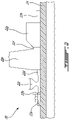
Figs. 3a-3c are cross-section views illustrating an assembly sequence of a pair of balancing rings on a rotating component having an initial unbalance that needs to be corrected, the balancing rings locked against rotation relative to the rotating component by a dual use spacer having an anti-rotation interface with the rings; -
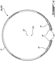
Fig. 4 is a front view of a balancing ring exemplified in the form of an internal circlip provided with anti-rotation lugs on its inner diameter surface for mating engagement with corresponding scallops provided on an outer diameter surface of the spacer; -
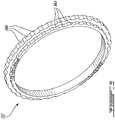
Fig. 5 is an isometric view of an exemplary spacer, the illustrated spacer having two arrays of circumferentially spaced-apart scallops on two different outer diameter surfaces for mating engagement with the anti-rotation lugs of two different sizes of balancing rings, the scallops and the lugs cooperating to provide an anti-rotation feature; -
Fig. 6 is an end view of a pair of balancing rings installed on the rotating component to be balanced and showing the rings clocked for a given unbalance correction; -
Fig. 7 is an end view of the assembled dual use spacer, the anti-rotation rings and the rotating component showing the anti-rotation capabilities of the spacer; -
Fig. 8 is an end view similar toFig. 7 but illustrating an embodiment in which external circlips are mounted to an outer diameter surface of a rotating component, the circlips having external lugs for anti-rotation engagement with mating scallops provided on an inner diameter surface of a dual use spacer; and -
Fig. 9 is a cross-section view taken along line 9-9 inFig. 8 . -
Fig. 1 illustrates agas turbine engine 10 of a type preferably provided for use in subsonic flight, generally comprising in serial flow communication afan 12 through which ambient air is propelled, acompressor section 14 for pressurizing the air, acombustor 16 in which the compressed air is mixed with fuel and ignited for generating an annular stream of hot combustion gases, and aturbine section 18 for extracting energy from the combustion gases. - The exemplified
engine 10 is a multi-spool engine including multiple rotating assemblies (e.g. a high pressure spool and a low pressure spool) mounted for rotation about an axis 11 (e.g. the engine centerline).Each rotating assembly may comprise a stack of rotating components axially clamped together on a shaft. For instance, each stack may comprise one or more compressor rotors, one or more turbine rotors, front and rear seal runners, one or more bearings, one or more oil scoops, and one or more spacers secured together on a shaft for rotation therewith. According to another example, the rotating assembly may consist of a transmission shaft with its associated gears and spacers. For instance, a rotating assembly could include a gear mounted to a transmission shaft with a spacer on the shaft to adjust a position of the gear relative to its pinion. The above examples of rotating assemblies are not intended to constitute an exhaustive list of all rotating assemblies found in gas turbine engines. - The term "spacer" is herein intended to generally refer to a purposely designed part introduced in a rotary stack to adjust the distance between two rotating components taking account of the stacked parts actual axial length. For example, in a turbo machine, spacers may be used to adjust the axial distance between the compressor and the turbine with respect to the stators to maximize engine performance. As mentioned above, spacers can also be used to adjust the position of a gear in relation to its pinion. Optimal spacer length is computed by measuring relevant dimensions in the rotary stack. The optimal computed spacer length is used to either grind an oversized part or is used to select a specific spacer length among pre-cut parts.
-
Fig. 2 is a simplified schematic view of anexemplary rotating assembly 20 comprising a number of rotatingcomponents 22a-22h axially clamped together on a rotatingshaft 24 for rotation aboutaxis 11 of thegas turbine engine 10. The rotatingassembly 20 needs to be balanced. A rotating unbalance is known as an uneven distribution of mass around an axis of rotation. A rotating component is said to be out of balance when its center of mass (inertia axis) is out of alignment with the center of rotation (geometric axis). Unbalance may cause a moment which gives the rotating component a wobbling movement characteristic of vibration of rotating structures. - As will be seen hereinafter, such a rotating unbalance may be corrected through the addition of dedicated balancing rings to an unbalance rotating component of a rotating assembly and by adjusting the relative angle between the balancing rings depending on the unbalance to be corrected. Once properly "clocked" (i.e. angularly oriented in the circumferential direction), the balancing rings are locked against rotation in their unbalance correction positions by a dual use spacer as exemplified in
Figs. 3-9 . -
Figs. 3a-3c illustrate an assembly sequence for correcting a rotating unbalance in a component of a given rotating assembly. More particularly,Figs. 3a-3c illustrates a rotating assembly 20' comprising aseal runner 22i' press fit to a shaft 24', aspacer 22j' mounted with a loose fit on the shaft 24' and axially abutted against theseal runner 22i' to allow for the adjustment of an axial position of theseal runner 22i' relative to another rotatingcomponent 22k', which is, in turn, press fit to the shaft 24' axially against thespacer 22j', thereby axially clamping thespacer 22j' in a secured position. Theseal runner 22i', thespacer 22j' and rotatingcomponent 22k' may correspond to some of the rotatingcomponents 22a-22h of the stack of rotating components shown inFig. 2 or they could be part of another rotating assembly of thegas turbine engine 10. - As exemplified in
Fig. 3a , one or more balancingrings seal runner 22i' to correct its initial rotating unbalance. According to the illustrated embodiment, the balancing rings comprise a pair ofbalancing rings Fig. 3a , thebalancing rings rings - The
balancing rings rotating axis 11 of the shaft 24' once therings seal runner 22i'. By adjusting the relative angular position of therings seal runner 22i' about the axis of shaft 24', a balancing force can be generated, the intensity of the balancing force being determined by the relative angular position between the twocounterbalance rings rings rings seal runner 22i'.Fig. 6 illustrates a relative angular orientation of the balancing rings 26a, 26b for correcting a given rotating unbalance of theseal runner 22i'. - As shown in
Fig. 4 , each balancingring Figs. 3a-3c ,4 ,6 and7 ) or external (Figs. 8-9 ), referring to whether it is fitted into the rotating component or thereover. Theexemplary circlip Fig. 4 is designed to be installed and removed with special pliers (not shown).Holes 28 can be defined in theend portions 30 of the circlip for engagement with the pliers. - As can be appreciated from
Fig. 4 , extra material can be provided at desired locations around the circumference of the circlip to offset the center of mass CM of thecirclip end portions 30 of the circlip. However, it is understood that it could be provided at other circumferential locations. The circlip illustrated inFig. 4 has a smoothouter diameter surface 32 for engagement with a corresponding smooth diameter surface of the associated retaining groove in theseal runner 22i'. The smooth circumferential interface between thecirclip seal runner 22i' allows to adjustably rotate the circlip relative to theseal runner 22i' about the axis of shaft 24' between an infinite number of angular positions (in contrast to a mounting arrangement offering discrete mounting positions in the circumferential direction) for correcting the rotating unbalance. That is the circlip shown inFig. 4 can be installed at virtually any angular position in the circumferential direction on therunner 22i'. The term "smooth" interface is used herein in opposition to mating surfaces having discrete positioning features for providing for incremental adjustment of the relative position of the two mating components between discrete positions. - One of the challenges in using balancing rings, such as circlips, is to lock their angular orientation to secure the unbalance correction once they have been assembled with the desired correction orientation on the rotating component to be balanced (as for instance shown in
Fig. 6 ). As shown inFigs. 3b and7 , it is herein proposed to use thespacer 22j' to secure the angular position of thecirclips seal runner 22i'. The integration of the anti-rotation function to an existing component (i.e. the spacer 22j') of the rotating assembly 20' eliminates the need for an additional anti-rotation component. Integrating this function to the spacer 22j' as opposed to theseal runner 22i' also allows for the above described smooth interface between theseal runner 22i' and thecirclips circlips seal runner 22i' during the balancing correction of a rotating unbalance. - As shown in
Fig. 7 , the spacer 22j' and thecirclips Figs. 3-7 , the anti-rotation interface comprises male portions, which can, for instance, take the form of built-in ears or lugs 34 (Figs. 4 and7 ) projecting from an inner diameter surface of thecirclips scallops Figs. 5 and7 ) provided on an outer diameter surface of the spacer 22j'. It is understood that the female portions could be provided on the inner diameter surface of thecirclips Fig. 4 , thelugs 34 are provided at theend portions 30 of thecirclip lugs 34 could be provided at other locations around the inner diameter surface of thecirclip lugs 34, it is understood that a different number oflugs 34 could be provided for engagement with corresponding scallops of the arrays ofscallops spacer 22j'. - Now referring more particularly to
Fig. 5 , it can be seen that the two arrays of circumferentially spaced-apartscallops spacer 22j' has a hollow cylinder body with two different outer diameter surfaces, each outer diameter surface having an array of circumferentially spaced-apartscallops circlips Figs. 3a-3c . Referring toFig. 3b , it can be seen that the smaller outer diameter portion of the spacer 22j' is abutted axially against an inner abutting surface of theseal runner 22i' to axially align the first array ofscallops 36a on the smaller outer diameter of the spacer 22j' with thesmaller diameter circlip 26a. The second arrays ofscallops 36b on the larger outer diameter of the spacer 22j' is axially aligned with thelarger diameter circlip 26b. The use of two different sizes ofcirclips first circlip 26a without having to first remove thesecond circlip 26b once bothcirclips runner 22i'. However, it is understood that only one size of circlips could be used. In this case, both arrays of circumferentially spaced-apartscallops - It can be appreciated that the spacer function of the spacer 22j' is provided by the axial length adjustment of the spacer, in the same fashion as a traditional spacer, and the anti-rotation function is provided by the
scallops lugs 34 in thescallops circlips scallops circlips spacer 22j'. Even though thespacer 22j' is designed to have a gap on its inner diameter and outer diameter, thespacer 22j' is clamped by the rotor stack compression preload viacomponent 22k', as shown inFig. 3c . Therefore, the friction load does not allow thespacer 22j' to move in any operating condition. - By using the
spacer 22j' to lock thecirclips seal runner 22i', the circlips can be positioned at any desired orientation during the balancing operation. In the case where only one circlip is used, it can be locked at any orientation. Where two circlips are used as described in connection with the illustrated embodiment, the spacer 22j' doubles as a go/no go gauge to assess the allowable position of one circlip in relation with the other one prior to the balancing validation operation. - It is understood that the exemplified
circlip spacer 22j' respectively shown inFigs. 4 and5 could vary in the circlip detail designed as well as scallops count and shape. Notably, the shape ofscallops lugs 34 within thescallops scallops lugs 34. It is understood that the profile of the scallops and mating lugs does not need to be circular. For instance, the lug/scallop could be designed in the same manner as a dovetail fitting. - The
seal runner 22i' of the rotating assembly 20' can be balanced in the following manner. Before an installation of thecirclips dual function spacer 22j', an initial rotating unbalance of therunner 22i' is determined in a manner already known in the art. A point of maximum unbalance on therunner 22i' is determined and a required balancing correction is computed. Using a simple computer program, chart or formula, a relative angular position required between the balancingrings circlips runner 22i' and the position thereof in the circumferential direction is adjusted to counteract the rotating unbalance of theseal runner 22i'. Then, thespacer 22j' is axially engaged with a loose fit on the shaft 24' and angularly positioned in the circumferential direction so as to align some of thescallops lugs 34 on thecirclips Fig. 7 ). Then, thespacer 22j' is axially abutted against therunner 22i' as shown inFig. 3b . In this position, thelugs 34 of thecirclips corresponding scallops component 22k' is press fit on the shaft 24' in clamping engagement with the spacer 22j', thereby axially and circumferentially securing the rotating assembly 20'. -
Figs. 8 and 9 illustrate another embodiment using the same parts, i.e. arotating component 22i" to be balanced, two different sizes ofcirclips 26a', 26b' mounted to therotating component 22i" for correcting the rotating unbalance, adual use spacer 22j" and aclamping component 22k", but with externally mounted circlips instead of internal ones. More particularly, the variant illustrated inFigs. 8 and 9 mainly differs from the embodiment shown inFigs. 3 to 7 in thatexternal circlips 26a', 26b' are mounted in respective grooves defined in an outer diameter surface of therotating component 22i" to be balanced. According to this variant, the lugs 34' project from the outer diameter of thecirclips 26a', 26b' for mating engagement with scallops of two corresponding arrays ofscallops 36a', 36b' defined in two different inner diameter surfaces of the spacer 22j". According to this variant, thecirclips 26a', 26b' may be snug into the scalloped inner diameter of the spacer 22j". In this configuration, the circlip positions are first adjusted outside of therotating component 22i". Then, the spacer 22j", to which thecirclips 26a' 26b' are clamped, is positioned in the rotor assembly and axially clamped withcomponent 22k" on shaft 24'. - The embodiments described in this document provide non-limiting examples of possible implementations of the present technology. Upon review of the present disclosure, a person of ordinary skill in the art will recognize that changes may be made to the embodiments described herein without departing from the scope of the present technology. For example, it is understood that the various described balancing arrangements can be applied to a wide variety of rotating assemblies and rotating components. Also, while the balancing rings have been described as circlips it is understood that other suitable forms of balancing rings could be used. Yet further modifications could be implemented by a person of ordinary skill in the art in view of the present disclosure, which modifications would be within the scope of the present technology.
Claims (14)
- A rotating assembly (20; 20') for a gas turbine engine (10), comprising:a first rotating component (22i'; 22i") mounted for rotation about an axis (11; GC);at least one balancing ring (26a, 26b; 26a', 26b') mounted to the first rotating component (22i'; 22i") and clocked at a circumferential position about the axis (11; GC) to counteract a rotating unbalance of the first rotating component (22i'; 22i"); anda spacer (22j'; 22j") axially abutted against the first rotating component (22i'; 22i") to set an axial position of the first rotating component (22i'; 22i") relative to a second rotating component (22k'; 22k") of the rotating assembly (20; 20'), the spacer (22j'; 22j") locking the at least one balancing ring (26a, 26b; 26a', 26b') against rotation relative to the first rotating component (22i'; 22i").
- The rotating assembly (20; 20') as defined in claim 1, wherein the spacer (22j'; 22j") and the at least one balancing ring (26a, 26b; 26a', 26b') have a circumferential interface with cooperating anti-rotation male/female portions (34, 36a, 36b).
- The rotating assembly (20; 20') as defined in claim 2, wherein the cooperating anti-rotation male/female portions (34, 36a, 36b; 34', 36a', 36b') include at least one lug (34; 34') projecting from a first one of the at least one balancing ring (26a, 26b; 26a', 26b') and the spacer (22j'; 22j") and at least one circumferential array of scallops (36a, 36b; 36a', 36b') on a second one of the at least one balancing ring (26a, 26b; 26a', 26b') and the spacer (22j'; 22j"), the at least one lug (34) being engageable with a selected one of the scallops (36a, 36b; 36a', 36b') of the at least one circumferential array of scallops (36a, 36b; 36a', 36b').
- The rotating assembly (20; 20') defined in claim 3, wherein the at least one circumferential array of scallops (36a, 36b; 36a', 36b') is provided on an inner or an outer diameter of the spacer (22j'; 22j").
- The rotating assembly (20; 20') defined in claim 3 or 4, wherein the at least one circumferential array of scallops (36a, 36b; 36a', 36b') includes a first and a second circumferential array of scallops (36a, 36b; 36a', 36b'), the first and second circumferential arrays of scallops (36a, 36b; 36a', 36b') being provided on two different diameters of the spacer (22j'; 22j"), and wherein the at least one balancing ring (26a, 26b; 26a', 26b') includes a first and a second circlip (26a, 26b; 26a', 26b'), the first and second circlips (26a, 26b; 26a', 26b') having different diameters for locking engagement with the first and second circumferential arrays of scallops (36a, 36b; 36a', 36b'), respectively.
- The rotating assembly (20; 20') as defined in any one of claims 1 to 5, wherein the at least one balancing ring (26a, 26b; 26a', 26b') is adjustably rotatable in a circumferential direction relative to the first rotating component (22i'; 22i") between an infinite number of circumferential positions.
- The rotating assembly (20; 20') as defined in any preceding claim, wherein the at least one balancing ring (26a, 26b; 26a', 26b') has a smooth circumferential surface engaged with a corresponding smooth circumferential seating surface on the first rotating component (22i'; 22i").
- The rotating assembly (20; 20') as defined in any one of claims 1 to 7, wherein the first rotating component (22i'; 22i") is press fit to a shaft (24'), the spacer (22j'; 22j") is mounted to the shaft (24') with a loose fit, wherein the spacer (22j'; 22j") is axially clamped between the first rotating component (22i'; 22i") and the second rotating component (22k'; 22k"), and wherein the second rotating component (22k'; 22k") is press fit to the shaft (24').
- The rotating assembly (20; 20') as defined in any one of claims 1 to 8, wherein the at least one balancing ring (26a, 26b; 26a', 26b') includes a circlip (26a, 26b; 26a', 26b') with built-in lugs (34; 34'), wherein the spacer is axially clamped in sandwich between the first and second rotating components (22i', 22k'; 22i", 22k") and has a scalloped circumferential surface in circumferential locking engagement with the built-in lugs (34; 34') of the circlip (26a, 26b; 26a', 26b'), thereby locking the circlip (26a, 26b; 26a', 26b') against rotation relative to the first rotating component (22i'; 22i").
- A method of balancing a first rotating component (22i'; 22i") of a stack of rotating components of a gas turbine engine (10), the first rotating component (22i'; 22i") mounted for rotation about an axis of rotation (11; GC), the method comprising:mounting at least one circlip (26a, 26b; 26a', 26b') in a corresponding seat on the first rotating component (22i'; 22i"), the at least one circlip (26a, 26b; 26a', 26b') having a center of mass (CM) offset from the axis of rotation (11; GC);adjusting an angular orientation of the at least one circlip (26a, 26b; 26a', 26b') relative to the first rotating component (22i'; 22i"), including rotating the at least one circlip (26a, 26b; 26a', 26b') about the axis of rotation (11; GC) to a circumferential position in which the at least one circlip (26a, 26b; 26a', 26b') counters a rotating unbalance of the first rotating component (22i'; 22i"); andlocking the at least one circlip (26a, 26b; 26a', 26b') against rotation relative to the first rotating component (22i'; 22i") using a spacer (22j'; 22j") axially clamped between the first rotating component (22i'; 22i") and a second rotating component (22k'; 22k") of the stack of rotating components.
- The method as defined in claim 10, comprising angularly aligning scallops (36a, 36b; 36a', 36b') distributed on a circumferential surface of the spacer (22j'; 22j") with corresponding lugs (34; 34') projecting from the circlip (26a, 26b; 26a', 26b') and axially sliding the spacer (22j'; 22j") along a shaft (24') in abutment against the first rotating component (22i'; 22i") so as to engage the lugs (34; 34') into the scallops (36a, 36b; 36a', 36b') aligned therewith.
- The method as defined in claim 11, comprising mounting the second rotating component (22k'; 22k") with a press fit to the shaft (24') and in axial abutment with the spacer (22j'; 22j").
- The method as defined in any of claims 10 to 12, wherein mounting at least one circlip (26a, 26b; 26a', 26b') comprises mounting first and second circlips (26a, 26b; 26a', 26b') on two different diameters of the first rotating component (22i'; 22i").
- The method as defined in claim 13, comprising engaging the first and second circlips (26a, 26b; 26a', 26b') in locking engagement with first and second scalloped surfaces, respectively, the first and second scalloped surfaces being provided on two different diameters of the spacer (22j'; 22j").
Applications Claiming Priority (1)
| Application Number | Priority Date | Filing Date | Title |
|---|---|---|---|
| US17/114,620 US11643931B2 (en) | 2020-12-08 | 2020-12-08 | Balancing ring anti-rotation spacer |
Publications (2)
| Publication Number | Publication Date |
|---|---|
| EP4019740A1 true EP4019740A1 (en) | 2022-06-29 |
| EP4019740B1 EP4019740B1 (en) | 2023-09-27 |
Family
ID=78825001
Family Applications (1)
| Application Number | Title | Priority Date | Filing Date |
|---|---|---|---|
| EP21213181.7A Active EP4019740B1 (en) | 2020-12-08 | 2021-12-08 | Rotor assembly having a balancing ring with an anti-rotation spacer |
Country Status (4)
| Country | Link |
|---|---|
| US (1) | US11643931B2 (en) |
| EP (1) | EP4019740B1 (en) |
| CA (1) | CA3140334A1 (en) |
| PL (1) | PL4019740T3 (en) |
Families Citing this family (3)
| Publication number | Priority date | Publication date | Assignee | Title |
|---|---|---|---|---|
| GB202218282D0 (en) * | 2022-12-06 | 2023-01-18 | Rolls Royce Plc | Rotor balancing apparatus |
| CN116557352A (en) * | 2023-06-06 | 2023-08-08 | 中国科学院工程热物理研究所 | Balance ring and blisk subassembly suitable for adjust blisk subassembly balancing volume |
| US12467365B1 (en) | 2025-01-27 | 2025-11-11 | Pratt & Whitney Canada Corp. | In situ balancing mass(es) for aircraft powerplant |
Citations (6)
| Publication number | Priority date | Publication date | Assignee | Title |
|---|---|---|---|---|
| US3964342A (en) * | 1974-07-22 | 1976-06-22 | General Motors Corporation | Turbine shaft balancing |
| US4294135A (en) * | 1979-01-12 | 1981-10-13 | The United States Of America As Represented By The Secretary Of The Navy | Turbomachine balance correction system |
| DE19920699A1 (en) * | 1999-05-05 | 2000-12-07 | Hofmann Mess Und Auswuchttechn | Method and device for balancing rotors, especially tools and tool holders, has balancing rings with a definite out-of-balance and mechanisms to fasten the rings to each other at an appropriate angle and to the unbalance on a rotor. |
| US20060083619A1 (en) * | 2004-10-20 | 2006-04-20 | Roever Douglas M | Dual counterweight balancing system |
| DE102011102315A1 (en) * | 2011-05-23 | 2012-11-29 | Rolls-Royce Deutschland Ltd & Co Kg | Gas turbine balancing device for use in turbo-engine of aircraft, has balancing rings rotatable by tool that is operated in mounted condition of gas turbine and fixed relative to each other and relative to groove by fixing device |
| FR3087481A1 (en) * | 2018-10-19 | 2020-04-24 | Safran Aircraft Engines | MODULAR BALANCING ASSEMBLY FOR TURBOMACHINE |
Family Cites Families (11)
| Publication number | Priority date | Publication date | Assignee | Title |
|---|---|---|---|---|
| US3964242A (en) | 1975-05-28 | 1976-06-22 | Agriculture Research Incorporated | Cotton harvesting machine |
| US6588298B2 (en) | 2001-03-23 | 2003-07-08 | United Technologies Corporation | Rotor balancing system for turbomachinery |
| US7912587B2 (en) | 2007-07-25 | 2011-03-22 | Pratt & Whitney Canada Corp. | Method of balancing a gas turbine engine rotor |
| US8631578B2 (en) | 2009-10-01 | 2014-01-21 | Pratt & Whitney Canada Corp. | Radial balancing clip weight for rotor assembly |
| US9957799B2 (en) * | 2012-09-19 | 2018-05-01 | United Technologies Corporation | Balance ring for gas turbine engine |
| US9003638B2 (en) * | 2013-03-11 | 2015-04-14 | Pratt & Whitney Canada Corp. | Method of assembling an electromechanical device in a gas-turbine engine |
| US10247003B2 (en) * | 2013-09-26 | 2019-04-02 | United Technologies Corporation | Balanced rotating component for a gas powered engine |
| WO2015088620A2 (en) * | 2013-09-26 | 2015-06-18 | United Technologies Corporation | Rotating component balance ring |
| US9638037B2 (en) | 2014-11-03 | 2017-05-02 | Pratt & Whitney Canada Corp. | Method of balancing a gas turbine engine rotor |
| US10383438B2 (en) | 2015-03-16 | 2019-08-20 | Cubex Llc | Devices for controlled dispensing |
| US10669875B2 (en) * | 2018-03-28 | 2020-06-02 | Solar Turbines Incorporated | Cross key anti-rotation spacer |
-
2020
- 2020-12-08 US US17/114,620 patent/US11643931B2/en active Active
-
2021
- 2021-11-23 CA CA3140334A patent/CA3140334A1/en active Pending
- 2021-12-08 PL PL21213181.7T patent/PL4019740T3/en unknown
- 2021-12-08 EP EP21213181.7A patent/EP4019740B1/en active Active
Patent Citations (6)
| Publication number | Priority date | Publication date | Assignee | Title |
|---|---|---|---|---|
| US3964342A (en) * | 1974-07-22 | 1976-06-22 | General Motors Corporation | Turbine shaft balancing |
| US4294135A (en) * | 1979-01-12 | 1981-10-13 | The United States Of America As Represented By The Secretary Of The Navy | Turbomachine balance correction system |
| DE19920699A1 (en) * | 1999-05-05 | 2000-12-07 | Hofmann Mess Und Auswuchttechn | Method and device for balancing rotors, especially tools and tool holders, has balancing rings with a definite out-of-balance and mechanisms to fasten the rings to each other at an appropriate angle and to the unbalance on a rotor. |
| US20060083619A1 (en) * | 2004-10-20 | 2006-04-20 | Roever Douglas M | Dual counterweight balancing system |
| DE102011102315A1 (en) * | 2011-05-23 | 2012-11-29 | Rolls-Royce Deutschland Ltd & Co Kg | Gas turbine balancing device for use in turbo-engine of aircraft, has balancing rings rotatable by tool that is operated in mounted condition of gas turbine and fixed relative to each other and relative to groove by fixing device |
| FR3087481A1 (en) * | 2018-10-19 | 2020-04-24 | Safran Aircraft Engines | MODULAR BALANCING ASSEMBLY FOR TURBOMACHINE |
Also Published As
| Publication number | Publication date |
|---|---|
| PL4019740T3 (en) | 2024-01-15 |
| EP4019740B1 (en) | 2023-09-27 |
| CA3140334A1 (en) | 2022-06-08 |
| US20220178259A1 (en) | 2022-06-09 |
| US11643931B2 (en) | 2023-05-09 |
Similar Documents
| Publication | Publication Date | Title |
|---|---|---|
| EP4019740B1 (en) | Rotor assembly having a balancing ring with an anti-rotation spacer | |
| EP2333243B1 (en) | Rotor with circumferential slot and corresponding assembly method | |
| US9121302B2 (en) | Radial compressor blade clearance control system | |
| US8074455B2 (en) | Gas turbine engine with a means of driving the accessory gear box, and method of fitting said engine | |
| US9702258B2 (en) | Adjustable transition support and method of using the same | |
| US10830081B2 (en) | Non-contact seal with non-straight spring beam(s) | |
| EP4001596B1 (en) | Gas turbine engine | |
| US20150204439A1 (en) | Variable vane actuating system | |
| EP2964886A1 (en) | Disc arrangement, retention system, and method of retaining two separate rotating members of a gas turbine machine | |
| EP3995670B1 (en) | Variable guide vane assembly for a gas turbine engine and gas turbine engine | |
| CA2894032C (en) | Single bolting flange arrangement for variable guide vane connection | |
| US10415405B2 (en) | Variable pitch fan blade system | |
| EP3124795A1 (en) | Turbojet engine fan disc and turbojet | |
| EP3715655B1 (en) | Bearing assembly | |
| US20240183273A1 (en) | Rotor balancing apparatus | |
| US10450890B2 (en) | Variable stator guide vane system | |
| CA2948262A1 (en) | Rotor assembly for use in a turbofan engine and method of assembling | |
| EP3489471A1 (en) | Engine bearing offset and load | |
| US10590957B2 (en) | Turbine engine compressor, in particular for an aircraft turboprop engine or turbojet engine | |
| US20260125983A1 (en) | Shaft assembly for a gas turbine engine | |
| US11268405B2 (en) | Bearing support structure with variable stiffness | |
| GB2544036A (en) | A planet carrier assembly for an epicyclic gearbox | |
| CA3068136A1 (en) | Gas turbine engine and rotary assembly therefore |
Legal Events
| Date | Code | Title | Description |
|---|---|---|---|
| PUAI | Public reference made under article 153(3) epc to a published international application that has entered the european phase |
Free format text: ORIGINAL CODE: 0009012 |
|
| STAA | Information on the status of an ep patent application or granted ep patent |
Free format text: STATUS: THE APPLICATION HAS BEEN PUBLISHED |
|
| AK | Designated contracting states |
Kind code of ref document: A1 Designated state(s): AL AT BE BG CH CY CZ DE DK EE ES FI FR GB GR HR HU IE IS IT LI LT LU LV MC MK MT NL NO PL PT RO RS SE SI SK SM TR |
|
| STAA | Information on the status of an ep patent application or granted ep patent |
Free format text: STATUS: REQUEST FOR EXAMINATION WAS MADE |
|
| 17P | Request for examination filed |
Effective date: 20221221 |
|
| RBV | Designated contracting states (corrected) |
Designated state(s): AL AT BE BG CH CY CZ DE DK EE ES FI FR GB GR HR HU IE IS IT LI LT LU LV MC MK MT NL NO PL PT RO RS SE SI SK SM TR |
|
| GRAP | Despatch of communication of intention to grant a patent |
Free format text: ORIGINAL CODE: EPIDOSNIGR1 |
|
| STAA | Information on the status of an ep patent application or granted ep patent |
Free format text: STATUS: GRANT OF PATENT IS INTENDED |
|
| INTG | Intention to grant announced |
Effective date: 20230614 |
|
| GRAS | Grant fee paid |
Free format text: ORIGINAL CODE: EPIDOSNIGR3 |
|
| GRAA | (expected) grant |
Free format text: ORIGINAL CODE: 0009210 |
|
| STAA | Information on the status of an ep patent application or granted ep patent |
Free format text: STATUS: THE PATENT HAS BEEN GRANTED |
|
| AK | Designated contracting states |
Kind code of ref document: B1 Designated state(s): AL AT BE BG CH CY CZ DE DK EE ES FI FR GB GR HR HU IE IS IT LI LT LU LV MC MK MT NL NO PL PT RO RS SE SI SK SM TR |
|
| REG | Reference to a national code |
Ref country code: GB Ref legal event code: FG4D |
|
| REG | Reference to a national code |
Ref country code: CH Ref legal event code: EP |
|
| REG | Reference to a national code |
Ref country code: DE Ref legal event code: R096 Ref document number: 602021005450 Country of ref document: DE |
|
| REG | Reference to a national code |
Ref country code: IE Ref legal event code: FG4D |
|
| REG | Reference to a national code |
Ref country code: LT Ref legal event code: MG9D |
|
| PG25 | Lapsed in a contracting state [announced via postgrant information from national office to epo] |
Ref country code: GR Free format text: LAPSE BECAUSE OF FAILURE TO SUBMIT A TRANSLATION OF THE DESCRIPTION OR TO PAY THE FEE WITHIN THE PRESCRIBED TIME-LIMIT Effective date: 20231228 |
|
| PG25 | Lapsed in a contracting state [announced via postgrant information from national office to epo] |
Ref country code: SE Free format text: LAPSE BECAUSE OF FAILURE TO SUBMIT A TRANSLATION OF THE DESCRIPTION OR TO PAY THE FEE WITHIN THE PRESCRIBED TIME-LIMIT Effective date: 20230927 Ref country code: RS Free format text: LAPSE BECAUSE OF FAILURE TO SUBMIT A TRANSLATION OF THE DESCRIPTION OR TO PAY THE FEE WITHIN THE PRESCRIBED TIME-LIMIT Effective date: 20230927 Ref country code: NO Free format text: LAPSE BECAUSE OF FAILURE TO SUBMIT A TRANSLATION OF THE DESCRIPTION OR TO PAY THE FEE WITHIN THE PRESCRIBED TIME-LIMIT Effective date: 20231227 Ref country code: LV Free format text: LAPSE BECAUSE OF FAILURE TO SUBMIT A TRANSLATION OF THE DESCRIPTION OR TO PAY THE FEE WITHIN THE PRESCRIBED TIME-LIMIT Effective date: 20230927 Ref country code: LT Free format text: LAPSE BECAUSE OF FAILURE TO SUBMIT A TRANSLATION OF THE DESCRIPTION OR TO PAY THE FEE WITHIN THE PRESCRIBED TIME-LIMIT Effective date: 20230927 Ref country code: HR Free format text: LAPSE BECAUSE OF FAILURE TO SUBMIT A TRANSLATION OF THE DESCRIPTION OR TO PAY THE FEE WITHIN THE PRESCRIBED TIME-LIMIT Effective date: 20230927 Ref country code: GR Free format text: LAPSE BECAUSE OF FAILURE TO SUBMIT A TRANSLATION OF THE DESCRIPTION OR TO PAY THE FEE WITHIN THE PRESCRIBED TIME-LIMIT Effective date: 20231228 Ref country code: FI Free format text: LAPSE BECAUSE OF FAILURE TO SUBMIT A TRANSLATION OF THE DESCRIPTION OR TO PAY THE FEE WITHIN THE PRESCRIBED TIME-LIMIT Effective date: 20230927 |
|
| REG | Reference to a national code |
Ref country code: NL Ref legal event code: MP Effective date: 20230927 |
|
| REG | Reference to a national code |
Ref country code: AT Ref legal event code: MK05 Ref document number: 1615617 Country of ref document: AT Kind code of ref document: T Effective date: 20230927 |
|
| PG25 | Lapsed in a contracting state [announced via postgrant information from national office to epo] |
Ref country code: NL Free format text: LAPSE BECAUSE OF FAILURE TO SUBMIT A TRANSLATION OF THE DESCRIPTION OR TO PAY THE FEE WITHIN THE PRESCRIBED TIME-LIMIT Effective date: 20230927 |
|
| PG25 | Lapsed in a contracting state [announced via postgrant information from national office to epo] |
Ref country code: IS Free format text: LAPSE BECAUSE OF FAILURE TO SUBMIT A TRANSLATION OF THE DESCRIPTION OR TO PAY THE FEE WITHIN THE PRESCRIBED TIME-LIMIT Effective date: 20240127 |
|
| PG25 | Lapsed in a contracting state [announced via postgrant information from national office to epo] |
Ref country code: AT Free format text: LAPSE BECAUSE OF FAILURE TO SUBMIT A TRANSLATION OF THE DESCRIPTION OR TO PAY THE FEE WITHIN THE PRESCRIBED TIME-LIMIT Effective date: 20230927 |
|
| PG25 | Lapsed in a contracting state [announced via postgrant information from national office to epo] |
Ref country code: ES Free format text: LAPSE BECAUSE OF FAILURE TO SUBMIT A TRANSLATION OF THE DESCRIPTION OR TO PAY THE FEE WITHIN THE PRESCRIBED TIME-LIMIT Effective date: 20230927 |
|
| PG25 | Lapsed in a contracting state [announced via postgrant information from national office to epo] |
Ref country code: SM Free format text: LAPSE BECAUSE OF FAILURE TO SUBMIT A TRANSLATION OF THE DESCRIPTION OR TO PAY THE FEE WITHIN THE PRESCRIBED TIME-LIMIT Effective date: 20230927 Ref country code: RO Free format text: LAPSE BECAUSE OF FAILURE TO SUBMIT A TRANSLATION OF THE DESCRIPTION OR TO PAY THE FEE WITHIN THE PRESCRIBED TIME-LIMIT Effective date: 20230927 Ref country code: IS Free format text: LAPSE BECAUSE OF FAILURE TO SUBMIT A TRANSLATION OF THE DESCRIPTION OR TO PAY THE FEE WITHIN THE PRESCRIBED TIME-LIMIT Effective date: 20240127 Ref country code: ES Free format text: LAPSE BECAUSE OF FAILURE TO SUBMIT A TRANSLATION OF THE DESCRIPTION OR TO PAY THE FEE WITHIN THE PRESCRIBED TIME-LIMIT Effective date: 20230927 Ref country code: EE Free format text: LAPSE BECAUSE OF FAILURE TO SUBMIT A TRANSLATION OF THE DESCRIPTION OR TO PAY THE FEE WITHIN THE PRESCRIBED TIME-LIMIT Effective date: 20230927 Ref country code: AT Free format text: LAPSE BECAUSE OF FAILURE TO SUBMIT A TRANSLATION OF THE DESCRIPTION OR TO PAY THE FEE WITHIN THE PRESCRIBED TIME-LIMIT Effective date: 20230927 Ref country code: SK Free format text: LAPSE BECAUSE OF FAILURE TO SUBMIT A TRANSLATION OF THE DESCRIPTION OR TO PAY THE FEE WITHIN THE PRESCRIBED TIME-LIMIT Effective date: 20230927 Ref country code: PT Free format text: LAPSE BECAUSE OF FAILURE TO SUBMIT A TRANSLATION OF THE DESCRIPTION OR TO PAY THE FEE WITHIN THE PRESCRIBED TIME-LIMIT Effective date: 20240129 |
|
| PG25 | Lapsed in a contracting state [announced via postgrant information from national office to epo] |
Ref country code: IT Free format text: LAPSE BECAUSE OF FAILURE TO SUBMIT A TRANSLATION OF THE DESCRIPTION OR TO PAY THE FEE WITHIN THE PRESCRIBED TIME-LIMIT Effective date: 20230927 |
|
| REG | Reference to a national code |
Ref country code: DE Ref legal event code: R097 Ref document number: 602021005450 Country of ref document: DE |
|
| PG25 | Lapsed in a contracting state [announced via postgrant information from national office to epo] |
Ref country code: DK Free format text: LAPSE BECAUSE OF FAILURE TO SUBMIT A TRANSLATION OF THE DESCRIPTION OR TO PAY THE FEE WITHIN THE PRESCRIBED TIME-LIMIT Effective date: 20230927 |
|
| PG25 | Lapsed in a contracting state [announced via postgrant information from national office to epo] |
Ref country code: DK Free format text: LAPSE BECAUSE OF FAILURE TO SUBMIT A TRANSLATION OF THE DESCRIPTION OR TO PAY THE FEE WITHIN THE PRESCRIBED TIME-LIMIT Effective date: 20230927 |
|
| PLBE | No opposition filed within time limit |
Free format text: ORIGINAL CODE: 0009261 |
|
| STAA | Information on the status of an ep patent application or granted ep patent |
Free format text: STATUS: NO OPPOSITION FILED WITHIN TIME LIMIT |
|
| PG25 | Lapsed in a contracting state [announced via postgrant information from national office to epo] |
Ref country code: LU Free format text: LAPSE BECAUSE OF NON-PAYMENT OF DUE FEES Effective date: 20231208 |
|
| PG25 | Lapsed in a contracting state [announced via postgrant information from national office to epo] |
Ref country code: MC Free format text: LAPSE BECAUSE OF FAILURE TO SUBMIT A TRANSLATION OF THE DESCRIPTION OR TO PAY THE FEE WITHIN THE PRESCRIBED TIME-LIMIT Effective date: 20230927 |
|
| REG | Reference to a national code |
Ref country code: BE Ref legal event code: MM Effective date: 20231231 |
|
| PG25 | Lapsed in a contracting state [announced via postgrant information from national office to epo] |
Ref country code: MC Free format text: LAPSE BECAUSE OF FAILURE TO SUBMIT A TRANSLATION OF THE DESCRIPTION OR TO PAY THE FEE WITHIN THE PRESCRIBED TIME-LIMIT Effective date: 20230927 Ref country code: LU Free format text: LAPSE BECAUSE OF NON-PAYMENT OF DUE FEES Effective date: 20231208 |
|
| 26N | No opposition filed |
Effective date: 20240628 |
|
| REG | Reference to a national code |
Ref country code: IE Ref legal event code: MM4A |
|
| PG25 | Lapsed in a contracting state [announced via postgrant information from national office to epo] |
Ref country code: IE Free format text: LAPSE BECAUSE OF NON-PAYMENT OF DUE FEES Effective date: 20231208 |
|
| PG25 | Lapsed in a contracting state [announced via postgrant information from national office to epo] |
Ref country code: BE Free format text: LAPSE BECAUSE OF NON-PAYMENT OF DUE FEES Effective date: 20231231 |
|
| PG25 | Lapsed in a contracting state [announced via postgrant information from national office to epo] |
Ref country code: SI Free format text: LAPSE BECAUSE OF FAILURE TO SUBMIT A TRANSLATION OF THE DESCRIPTION OR TO PAY THE FEE WITHIN THE PRESCRIBED TIME-LIMIT Effective date: 20230927 |
|
| PG25 | Lapsed in a contracting state [announced via postgrant information from national office to epo] |
Ref country code: SI Free format text: LAPSE BECAUSE OF FAILURE TO SUBMIT A TRANSLATION OF THE DESCRIPTION OR TO PAY THE FEE WITHIN THE PRESCRIBED TIME-LIMIT Effective date: 20230927 Ref country code: IE Free format text: LAPSE BECAUSE OF NON-PAYMENT OF DUE FEES Effective date: 20231208 Ref country code: BE Free format text: LAPSE BECAUSE OF NON-PAYMENT OF DUE FEES Effective date: 20231231 |
|
| PG25 | Lapsed in a contracting state [announced via postgrant information from national office to epo] |
Ref country code: BG Free format text: LAPSE BECAUSE OF FAILURE TO SUBMIT A TRANSLATION OF THE DESCRIPTION OR TO PAY THE FEE WITHIN THE PRESCRIBED TIME-LIMIT Effective date: 20230927 |
|
| PG25 | Lapsed in a contracting state [announced via postgrant information from national office to epo] |
Ref country code: BG Free format text: LAPSE BECAUSE OF FAILURE TO SUBMIT A TRANSLATION OF THE DESCRIPTION OR TO PAY THE FEE WITHIN THE PRESCRIBED TIME-LIMIT Effective date: 20230927 |
|
| PG25 | Lapsed in a contracting state [announced via postgrant information from national office to epo] |
Ref country code: CY Free format text: LAPSE BECAUSE OF FAILURE TO SUBMIT A TRANSLATION OF THE DESCRIPTION OR TO PAY THE FEE WITHIN THE PRESCRIBED TIME-LIMIT; INVALID AB INITIO Effective date: 20211208 |
|
| REG | Reference to a national code |
Ref country code: CH Ref legal event code: PL |
|
| PG25 | Lapsed in a contracting state [announced via postgrant information from national office to epo] |
Ref country code: CH Free format text: LAPSE BECAUSE OF NON-PAYMENT OF DUE FEES Effective date: 20241231 |
|
| PG25 | Lapsed in a contracting state [announced via postgrant information from national office to epo] |
Ref country code: TR Free format text: LAPSE BECAUSE OF FAILURE TO SUBMIT A TRANSLATION OF THE DESCRIPTION OR TO PAY THE FEE WITHIN THE PRESCRIBED TIME-LIMIT Effective date: 20230927 |
|
| PGFP | Annual fee paid to national office [announced via postgrant information from national office to epo] |
Ref country code: DE Payment date: 20251126 Year of fee payment: 5 |
|
| PGFP | Annual fee paid to national office [announced via postgrant information from national office to epo] |
Ref country code: GB Payment date: 20251119 Year of fee payment: 5 |
|
| PGFP | Annual fee paid to national office [announced via postgrant information from national office to epo] |
Ref country code: FR Payment date: 20251120 Year of fee payment: 5 |
|
| PGFP | Annual fee paid to national office [announced via postgrant information from national office to epo] |
Ref country code: CZ Payment date: 20251205 Year of fee payment: 5 |
|
| PGFP | Annual fee paid to national office [announced via postgrant information from national office to epo] |
Ref country code: PL Payment date: 20251124 Year of fee payment: 5 |
|
| P01 | Opt-out of the competence of the unified patent court (upc) registered |
Free format text: CASE NUMBER: UPC_APP_0000225_4019740/2026 Effective date: 20260105 |
|
| PG25 | Lapsed in a contracting state [announced via postgrant information from national office to epo] |
Ref country code: HU Free format text: LAPSE BECAUSE OF FAILURE TO SUBMIT A TRANSLATION OF THE DESCRIPTION OR TO PAY THE FEE WITHIN THE PRESCRIBED TIME-LIMIT; INVALID AB INITIO Effective date: 20211208 |