EP4019726A1 - Sash window assemblies - Google Patents
Sash window assemblies Download PDFInfo
- Publication number
- EP4019726A1 EP4019726A1 EP21216296.0A EP21216296A EP4019726A1 EP 4019726 A1 EP4019726 A1 EP 4019726A1 EP 21216296 A EP21216296 A EP 21216296A EP 4019726 A1 EP4019726 A1 EP 4019726A1
- Authority
- EP
- European Patent Office
- Prior art keywords
- pivot shoe
- sash
- cam
- frame
- mounting frame
- Prior art date
- Legal status (The legal status is an assumption and is not a legal conclusion. Google has not performed a legal analysis and makes no representation as to the accuracy of the status listed.)
- Pending
Links
Images




Classifications
-
- E—FIXED CONSTRUCTIONS
- E06—DOORS, WINDOWS, SHUTTERS, OR ROLLER BLINDS IN GENERAL; LADDERS
- E06B—FIXED OR MOVABLE CLOSURES FOR OPENINGS IN BUILDINGS, VEHICLES, FENCES OR LIKE ENCLOSURES IN GENERAL, e.g. DOORS, WINDOWS, BLINDS, GATES
- E06B3/00—Window sashes, door leaves, or like elements for closing wall or like openings; Layout of fixed or moving closures, e.g. windows in wall or like openings; Features of rigidly-mounted outer frames relating to the mounting of wing frames
- E06B3/32—Arrangements of wings characterised by the manner of movement; Arrangements of movable wings in openings; Features of wings or frames relating solely to the manner of movement of the wing
- E06B3/34—Arrangements of wings characterised by the manner of movement; Arrangements of movable wings in openings; Features of wings or frames relating solely to the manner of movement of the wing with only one kind of movement
- E06B3/42—Sliding wings; Details of frames with respect to guiding
- E06B3/44—Vertically-sliding wings
- E06B3/4415—Double-hung, i.e. with two vertical sliding panels
-
- E—FIXED CONSTRUCTIONS
- E05—LOCKS; KEYS; WINDOW OR DOOR FITTINGS; SAFES
- E05D—HINGES OR SUSPENSION DEVICES FOR DOORS, WINDOWS OR WINGS
- E05D13/00—Accessories for sliding or lifting wings, e.g. pulleys, safety catches
- E05D13/04—Fasteners specially adapted for holding sliding wings open
- E05D13/08—Fasteners specially adapted for holding sliding wings open acting by friction for vertically sliding wings
-
- E—FIXED CONSTRUCTIONS
- E05—LOCKS; KEYS; WINDOW OR DOOR FITTINGS; SAFES
- E05D—HINGES OR SUSPENSION DEVICES FOR DOORS, WINDOWS OR WINGS
- E05D15/00—Suspension arrangements for wings
- E05D15/16—Suspension arrangements for wings for wings sliding vertically more or less in their own plane
- E05D15/22—Suspension arrangements for wings for wings sliding vertically more or less in their own plane allowing an additional movement
-
- E—FIXED CONSTRUCTIONS
- E05—LOCKS; KEYS; WINDOW OR DOOR FITTINGS; SAFES
- E05D—HINGES OR SUSPENSION DEVICES FOR DOORS, WINDOWS OR WINGS
- E05D7/00—Hinges or pivots of special construction
- E05D7/10—Hinges or pivots of special construction to allow easy separation or connection of the parts at the hinge axis
- E05D7/1061—Hinges or pivots of special construction to allow easy separation or connection of the parts at the hinge axis in a radial direction
- E05D7/1066—Hinges or pivots of special construction to allow easy separation or connection of the parts at the hinge axis in a radial direction requiring a specific angular position
- E05D7/1072—Hinges or pivots of special construction to allow easy separation or connection of the parts at the hinge axis in a radial direction requiring a specific angular position the pin having a non-circular cross-section
-
- E—FIXED CONSTRUCTIONS
- E05—LOCKS; KEYS; WINDOW OR DOOR FITTINGS; SAFES
- E05Y—INDEXING SCHEME ASSOCIATED WITH SUBCLASSES E05D AND E05F, RELATING TO CONSTRUCTION ELEMENTS, ELECTRIC CONTROL, POWER SUPPLY, POWER SIGNAL OR TRANSMISSION, USER INTERFACES, MOUNTING OR COUPLING, DETAILS, ACCESSORIES, AUXILIARY OPERATIONS NOT OTHERWISE PROVIDED FOR, APPLICATION THEREOF
- E05Y2201/00—Constructional elements; Accessories therefor
- E05Y2201/60—Suspension or transmission members; Accessories therefor
- E05Y2201/622—Suspension or transmission members elements
- E05Y2201/638—Cams; Ramps
-
- E—FIXED CONSTRUCTIONS
- E05—LOCKS; KEYS; WINDOW OR DOOR FITTINGS; SAFES
- E05Y—INDEXING SCHEME ASSOCIATED WITH SUBCLASSES E05D AND E05F, RELATING TO CONSTRUCTION ELEMENTS, ELECTRIC CONTROL, POWER SUPPLY, POWER SIGNAL OR TRANSMISSION, USER INTERFACES, MOUNTING OR COUPLING, DETAILS, ACCESSORIES, AUXILIARY OPERATIONS NOT OTHERWISE PROVIDED FOR, APPLICATION THEREOF
- E05Y2800/00—Details, accessories and auxiliary operations not otherwise provided for
- E05Y2800/67—Materials; Strength alteration thereof
- E05Y2800/676—Plastics
-
- E—FIXED CONSTRUCTIONS
- E05—LOCKS; KEYS; WINDOW OR DOOR FITTINGS; SAFES
- E05Y—INDEXING SCHEME ASSOCIATED WITH SUBCLASSES E05D AND E05F, RELATING TO CONSTRUCTION ELEMENTS, ELECTRIC CONTROL, POWER SUPPLY, POWER SIGNAL OR TRANSMISSION, USER INTERFACES, MOUNTING OR COUPLING, DETAILS, ACCESSORIES, AUXILIARY OPERATIONS NOT OTHERWISE PROVIDED FOR, APPLICATION THEREOF
- E05Y2900/00—Application of doors, windows, wings or fittings thereof
- E05Y2900/10—Application of doors, windows, wings or fittings thereof for buildings or parts thereof
- E05Y2900/13—Type of wing
- E05Y2900/148—Windows
Definitions
- the present invention concerns sash windows. More particularly, but not exclusively, this invention concerns an assembly for removably mounting a sash to a window frame.
- Sash windows typically comprise at least one window sash that is movable along a window frame to open or close the sash window. This type of window arrangement has been known for many years.
- Modern sash windows can be configured to tilt in use so that the outer surface of the window can be cleaned by someone located inside the building to which the sash window is mounted. Some tilting sash windows are also configured to be easily removed from the window frame without the need for specialist tools.
- a benefit of this type of arrangement is that the sashes can be easily removed from the frame prior to installation of the frame in a building. The frame can then be fixed to the building and the sashes quickly installed in the frame.
- a further benefit of this sort of arrangement is that the sashes can be easily removed at a later date for maintenance purposes.
- Prior art sash windows are typically configured for removal via a single removal method.
- the sash may be configured to tilt and be completely lifted out of the frame.
- Such a configuration is sometimes referred to as a "lift-off' configuration.
- the sash may be configured to tilt and be slidably removed from the frame while leaving part of a mounting assembly fixed in the frame.
- Such a configuration is sometimes referred to as a "slide-off' configuration.
- the customer would have to choose between a lift-off or slide-off sash window, depending on preference.
- some window manufacturers may have to make both lift-off and slide-off variants to meet the needs of different customers.
- the present invention seeks to mitigate the above-mentioned problems. Alternatively or additionally, the present invention seeks to provide improved apparatus for attaching a sash to a window frame.
- the present invention provides, according to a first aspect, an assembly for attaching a sash to a window frame.
- the assembly comprises a mounting frame for mounting to the sash and a pivot shoe, wherein the mounting frame comprises a mounting portion slidably mounted to an arm portion, and the arm portion is pivotally mounted to the pivot shoe, wherein the mounting frame is pivotable with respect to the pivot shoe from an untilted position to a first tilted position in which the mounting frame can be removed from the pivot shoe, and a second tilted position in which the mounting portion can be slidably removed from the arm portion.
- the pivot shoe and mounting frame assembly thereby provides both a lift-off and slide-off functionality.
- lift-off' removal of a sash the sash is tilted to move the mounting frame to the first tilted position, the sash can be removed by lifting the mounting frame out of the pivot shoe, while leaving the pivot shoe retained within the window frame.
- the sash is tilted to move the mounting frame to the second tilted position, the sash can then be removed by sliding the mounting portion away from the arm portion, while leaving the arm portion mounted to the pivot shoe.
- the assembly according to the first embodiment of the invention can enable sash window manufacturers to reduce the number of different types of windows that they produce, as they may no longer need to produce separate lift-off and slide-off sash windows. Furthermore, the end user is provided with two options for removing the sash, as opposed to the one option provided by a lift-off only or slide-off only sash window.
- the first position and second position may be substantially the same position.
- the first position and the second position may be different positions. There may be two or more positions which correspond to the first position. There may be two or more positions which correspond to the second position.
- One of the arm portion and the pivot shoe may comprise a pin and the other of the arm portion and the pivot shoe is formed with a slot, and wherein the mounting frame is pivotally mounted to the pivot shoe via the pin which is received within the slot and rotates within the slot as the mounting frame is pivoted with respect to the pivot shoe, and wherein the slot and pin are configured such that the pin is removable from the slot when the mounting frame is in in the first position and wherein the pin is locked within the slot when the mounting frame is pivoted away from the first position.
- the sash may therefore be prevented from being lifted away from the pivot shoe when the mounting frame is not in the first position by the locking member being locked in the slot.
- the sash mounting portion is prevented from being removed from the pivot shoe by the pin being locked within the slot during sliding movement of the sash with respect to the window frame.
- the pivot shoe may comprise the pin and the arm portion may be formed with the slot.
- the arm portion may comprise the pin and the pivot shoe may be formed with the slot.
- the pin may comprise formations configured to engage with a part of the locking mechanism that retains the pin within the slot.
- the pin may be a T-shaped pin.
- the pin may be an end casting.
- the pivot shoe may comprise a brake configured to engage with the window frame when the mounting frame is pivoted away from the untilted position.
- the brake may therefore be engaged when the mounting frame is in the first and/or second positions.
- the brake thereby prevents unwanted movement of the pivot shoe when the window sash is being removed from the window frame.
- Rotation of the pin within the slot may cause the brake to engage.
- the brake may be configured to become engaged when the pin is rotated through a predetermined angle.
- the predetermined angle may be greater than 20 degrees. For example, the predetermined angle may be approximately 30 degrees.
- the mounting portion may be formed with a sleeve and the arm portion may be slidably mounted within the sleeve.
- the arm portion may be formed with a sleeve and the mounting portion may be slidably mounted within the sleeve.
- the mounting portion may be substantially L shaped and configured to be fixed to perpendicular sides of the window sash.
- the mountain frame may comprise a locking mechanism to prevent relative sliding movement between the mounting portion and the arm portion.
- the locking mechanism may be unlocked to allow relative sliding movement between the mounting portion and the arm portion.
- the locking mechanism may be provided by snap-fit features formed on the mounting portion and the arm portion. Alternatively, the locking mechanism may be provided by, for example, a latch.
- the present invention provides, according to a second aspect, a pivot shoe for an assembly for attaching a sash to a window frame.
- the pivot shoe comprises a rotatable cam member and a first braking member, and wherein rotation of the rotatable cam member is configured to be coupled to the tilting of a window sash, and wherein rotation of the rotatable cam member about a cam axis causes the first braking member to move in a direction substantially perpendicular to the cam axis to engage the frame of a window in a direction substantially perpendicular to the cam axis.
- the pivot shoe thereby provides an automatic braking function which is coupled to the tilting of a window sash, so that the braking shoe is prevented from unwanted movement when the window sash is tilted and, optionally, removed.
- the pivot shoe may comprise a second braking member located on the opposite side of the cam axis to the first braking member, wherein rotation of the rotatable cam member about the cam axis causes the first braking member and second braking member to move in substantially opposite directions.
- the first braking member may comprise a resiliently deformable material which is resiliently deformed when the first braking member is moved in a direction substantially perpendicular to the cam axis. The first braking member may therefore return to its undeformed shape when not in use.
- the second braking member may also comprise a resiliently deformable material which is resiliently deformed when moving the second braking member in a direction substantially perpendicular to the cam axis. The second braking member may therefore return to its undeformed shape when not in use.
- the first braking member may comprise an arm formed by a body of the pivot shoe.
- the second braking member may comprise an arm formed by a body of the pivot shoe.
- the first and second arms may be positioned on opposite sides of the cam axis.
- the pivot shoe may comprise a moveable cam member which engages with the rotatable cam such that rotation of the rotatable cam member moves the moveable cam member along the cam axis in a first direction, and wherein movement of the moveable cam member in the first direction causes the moveable cam member to engage with the first braking member and move the first braking member in the direction substantially perpendicular to the cam axis.
- An end of the rotatable cam member may be formed with cam surfaces which engage with corresponding cam surfaces on the moveable cam member so that the moveable cam member is pushed along the cam axis by the camming engagement of the cam surfaces as the rotatable cam member is rotated.
- the first braking member may comprise a cam surface which engages with a cam surface of the moveable cam member.
- Movement of the moveable cam member along the cam axis may cause the moveable cam member to engage with the second braking member and move the second braking member in the direction substantially perpendicular to the cam axis.
- the second braking member may comprise a cam surface which engages with a cam surface of the moveable cam member.
- the moveable cam member may comprise a third braking member configured to engage the sash of a window frame in a direction substantially parallel to the cam axis.
- the pivot shoe may be configured such that rotation of the rotatable cam member by a predetermined angle about the cam axis may cause one or more braking member to engage the frame of a window.
- the predetermined angle may be greater than 20 degrees.
- the predetermined angle may be between 20 and 60 degrees.
- the predetermined angle may be approximately 30 degrees.
- the predetermined angle may be approximately 45 degrees.
- the reaction force due to the resiliently deformed first braking member trying to return to its undeformed shape may be configured to move the moveable cam member along the cam axis in a second, opposite direction to the first direction.
- the reaction force due to the resiliently deformed second braking member trying to return to its undeformed shape may be configured to move the moveable cam member along the cam axis in the second, opposite direction.
- the present invention provides, according to a third aspect, a sash window assembly comprising an assembly according to the first aspect of the invention, wherein the pivot shoe is mounted within a window frame of the assembly and the mounting frame is attached to a window sash of the assembly.
- the present invention provides, according to a fourth aspect, a kit of parts for forming a pivot shoe and mounting frame assembly, the kit of parts comprising a pivot shoe and mounting frame according to the first aspect of the invention.
- the present invention provides, according to a fourth aspect, a sash window assembly comprising a pivot shoe according to the second aspect of the invention, wherein the pivot shoe is mounted within a window frame of the assembly.
- a sash window 100 comprising a two window vertically moving sashes 101 mounted in a window frame 102 is shown schematically in FIG. 1 .
- Each window sash 101 is attached to the window frame 102 via two pivot shoe and mounting frame assemblies 200 according to an embodiment of the invention.
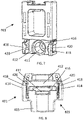
- One of the pivot shoe and mounting frame assemblies 200 is shown in isolation in FIG. 2 .
- the assembly 200 comprises a mounting frame 300 for mounting to the sash 101 and a pivot shoe 400 which is configured to be slidably mounted within the window frame 102.
- the pivot shoe and mounting frame assembly 200 enables the sash 101 to be slidably mounted in the frame 102 and slidable relative to the frame 102 to open and close the sash window 100.
- the pivot shoe 400 comprises a generally cuboidal main body 401 formed from a resilient plastics material.
- a pin-receiving portion 405 projects from the main body 40 and a pin channel 406 comprising a neck 408 is formed in the pin-receiving portion 405.
- the pivot shoe 400 also comprises a braking member 440 and a rotatable cam member 450 mounted within the main body 401.
- the braking member 440 and rotatable cam member 450 are shown outside of the main body 401 in FIG. 5 and FIG. 6 , and the main body 401 is shown without the braking member 440 and rotatable cam member 450 in FIG. 7 and FIG. 8 .
- the main body 401 On the frame-side 410 of the main body 401, the main body 401 is formed with a recess 412 for accommodating the braking member 440 within the main body 401.
- the recess is formed on its lateral sides by two braking arms 414 which project outwardly from the base 416 of the recess 412.
- a cylindrical channel 411 which, in use, contains the barrel section 452 of the cam rotatable cam member 450 connects the base 416 of the recess 412 with the sash-side 403 of the main body 401.
- the braking arms 414 comprise sloping cam surfaces 420 that slope into the recess 412, as can be best seen in FIG. 8 .
- the slope of the cam surfaces 420 is oriented such that the cam surfaces 420 slope further into the recess 412 when moving away from the base 416 of the recess 412.
- the rotatable cam member 450 comprises a cylindrical barrel section 451 connected to a circular cam plate 452 along a cam axis C.
- the cam plate 452 is formed with two cam wedges 456 which project outwardly from the cam plate 452, along the cam axis C.
- the cam wedges 456 are defined by circular sectors of the cam plate 452 and are arranged diametrically opposite one another, either side of the cam axis C.
- Each cam wedge 456 comprises sloping cam surfaces 458 which slope between the cam plate 452 and the top 460 of the cam wedge 456.
- a notch 462 which extends along the cam axis C is formed in the barrel section 451 of the cam member 450.
- the braking member 440 is generally plate-like and is shaped to be received in the recess 416 of the main body 401 of the pivot shoe 400.
- the braking member 440 is provided with a planar braking face 441.
- the braking member 440 comprises a cam face 442 which is formed with two cam recesses 443.
- the cam recesses 443 are shaped to receive the cam wedges 456 of the rotatable cam member 450, and so are defined by circular sectors which are arranged diametrically opposite one another.
- Each of the cam recesses 443 comprises sloping cam surfaces 444 which slope between the cam face 442 and the base 445 of the cam recess 443.
- the braking member 440 On the lateral sides 446 of the braking member 440, the braking member 440 is formed with lateral cam surfaces 447 which slope outwardly moving from the braking face 441 to the cam face 442.
- the braking member 440 is contained within the recess 412 of the main body 401 of the pivot shoe 400 and the barrel section 452 of the cam rotatable cam member 450 is contained within the cylindrical channel 411 of the pivot shoe 400, as shown in FIG. 3 and FIG. 4 .
- the cam wedges 456 of the rotatable cam member 456 sit within the cam recesses 443 of the braking member 440.
- the notch 463 of the rotatable cam member 450 is oriented such that a side 466 of the notch 463 blocks the neck 408 of the pin channel 406, as shown in FIG. 4 .
- a pin 327 of the mounting frame assembly 300 is prevented from being removed from the pin channel 406, and is therefore locked in the pin channel 406, as will be described below.
- the mounting frame 300 comprises mounting portion 301 and an arm portion 320.
- the mounting portion 301 is L-shaped and is formed by an elongate bottom portion 302 and an elongate sleeve section 303.
- the mounting portion 301 is formed with apertures 304 for fixing the mounting portion to a sash 101 with the bottom section 302 being fixed along the bottom of the sash 101 and the sleeve section being fixed along a side of the sash 101, as shown in FIG. 1 .
- the sleeve section 303 defines a channel 305, which can be best seen in FIG. 13 , that runs along the length of the sleeve section 303, with an entrance 307 to the channel 305 being provided at the end of the sleeve section 303 adjacent the bottom portion 302.
- a locking block 310 made from a plastics material is contained within the channel 305.
- the locking block 310 is formed with a generally circular locking portion 311 which projects into the channel 305 and is configured to snap-fit with a complementarily shaped circular recess 321 formed in the arm portion 320, as will be described in more detail below.
- the arm portion 320 which is shown in isolation in FIG. 9 , comprises an elongate body 322 which is shaped to be received within the sleeve section 303 of the mounting portion 301.
- the body 322 is formed with the aforementioned circular recess 321 for forming a snap-fit connection with the mounting portion 301.
- a T-shaped pin 327 provided by an end casting projects outwardly from the body 322, in a direction substantially perpendicular to a longitudinal axis Y and a transverse axis X defined by the body 322.
- the T-shaped pin 327 is oriented such that the top-portion 328 of the T-shape is aligned with a transverse axis X defined by the body 322.
- the pivot shoe and mounting frame assembly 200 is arranged as shown in FIG. 1 and FIG. 2 .
- the mounting frame 300 is attached to the sash 101 and the T-shaped pin 327 of the mounting frame is located in the pin channel 406 of the pivot shoe 400, with the pivot shoe being located in a window frame. Opening and closing of the sash window 100 can be achieved by moving the sash 101 relative to the frame 102, along the longitudinal axis L. This movement moves the pivot shoe within the window frame, as is well known in the art.
- the T-shaped pin 327 is prevented from being removed from the notch of 463 by the side 466 of the notch 463 blocking the neck 408 of the pin channel 406, as shown in FIG. 4 .
- the pivot shoe 300 that has been described above provides a braking function to fix the position of the braking shoe 300 within the window frame 102 when the sash 101 being removed.
- the sash 101 is rotated about the about an axis of rotation R which is indicated in FIG. 10 .
- the T-shaped pin 327 which is located in the notch 462 of the rotatable cam member 450, engages with the internal faces of the notch 462 and causes the rotatable cam member 450 to rotate.
- Rotation of the rotatable cam member 450 causes the cam surfaces 458 of the cam wedges 456 of the rotatable cam member 450 to engage with the cam surfaces 444 of the cam recesses 445 of the braking member 440, which in turn causes the braking member 440 to be pushed away from the rotatable cam member 450.
- the braking member 440 As the braking member 440 is pushed away from the rotatable cam member 450, the lateral cam surfaces 447 of the braking member 440 engage with the cam surfaces 420 on the braking arms 414 to push the braking arms 414 such that they resiliently deform outwardly and into engagement with the internal surfaces at the front and the rear of the window frame 102. Furthermore, the braking face 441 of the braking member 440 is pushed out of the recess 412 of the pivot shoe 400 and into engagement with the transverse internal surfaces of the widow frame (the transverse internal surfaces being oriented perpendicularly to the front and rear internal surfaces).
- the cam wedges 456 of the rotatable cam member 450 and the complementarily shaped cam recesses 443 of the braking member 440 are dimensioned such that rotation of the cam member 450 by approximately 30 degrees moves the cam wedges 456 completely out of the cam recesses 443. As such, the braking function is fully engaged once the rotatable cam member 450 has been rotated by approximately 30 degrees. Therefore, rotation of the mounting frame 300 by approximately 30 degrees causes the braking arms 414 and braking member 440 to deploy to the configuration shown in FIG. 10 to fix the position of the pivot shoe 400 within the window frame 102.
- the rotatable cam member 450 and braking member 440 are configured so that the braking function is fully engaged once the rotatable cam member 450 has been rotated by approximately 30 degrees.
- the rotatable cam member and braking member may be configured so that the braking function becomes fully engaged by rotating the rotatable cam member through a different angle, which may be greater or less than 30 degrees.
- the sash 101 is rotated back to an angle of less than 30 degrees. This causes the T-shaped pin 327 to rotate the rotatable cam member 450 back to a position in which the cam wedges 456 of the rotatable cam member 450 are aligned with the complementarily shaped cam recesses 443 of the braking member 440. As this happens, the reaction force created by the resiliently deformed braking arms 414 trying to return to their undeformed shape, which acts on the lateral cam surfaces 447 of the braking member 440, pulls the braking member 440 back into the recess 412 of the pivot shoe 400 as the braking arms 414 return to their undeformed shape.
- the pivot shoe and mounting frame assembly 200 provides two ways in which the sash 100 can be tilted and removed from the window frame 102 in use.
- the first method is a "lift-off' method, and will be described with reference to FIG. 11 and FIG. 12 .
- the sash 101 is tilted by 90 degrees with respect to the window frame 102 such that the mounting frame is oriented as shown in FIG. 11 .
- the braking function provided by the pivot shoe 400 has been engaged, and the notch 462 of the rotatable cam member 450 has been rotated into alignment with the neck 408 of the pin channel 406 of the pivot shoe 400 such that the T-shaped pin 327 can be lifted out of the pin channel 406, as shown in FIG. 12 .
- the sash 101 can therefore be removed from the window frame by lifting the T-shaped pins 327 of the mounting frames 300 out of their respective pin channels 406.
- the T-shaped pins 327 must be placed back into their respective pin channels, and the sash 102 must then be rotated back to the position in which it is aligned with the window frame. While this embodiment of the invention requires the sash 101 to be rotated by 90 degrees with respect to the window frame 102 to remove the sash 101, other embodiments of the invention may be configured such that the sash can be removed by rotating it to a different angle.
- the second method of removing the sash 100 from the window frame 102 is a "slide-off' method, and will be described with reference to FIG. 13 and FIG. 14 .
- the sash 101 is rotated with respect to the window frame 102 to an angle of at least 30 degrees so that the braking function provided by the pivot shoe 400 engages.
- the sleeve section 303 can then be slid off from the arm portion 320 to remove the sash 101 from the window frame 102. This process leaves the arm portions 320 mounted to the pivot shoe 400 while the sash 101 is removed.
- the arm portions 320 When removing the sash 101, enough force must be applied to the sleeve section 303 to remove the snap-fitting circular projecting portion 311 of the locking block 310 from the circular recess 321 in the arm portion 320 of the mounting frame.
- the arm portions 320 To replace the sash 101, the arm portions 320 must be relocated in the channels 305 of their respective mounting frames and slid into the channels 305 until the snap-fit between the locking block 310 and the arm portion 320 engages.
- the angle at which the sash 101 is rotated to in order to remove it using the slide-off method is determined by the angle at which the pivot shoe 400 braking is configured to engage. However, if braking is not required, the sash 101 needs only to be rotated to a position in which enough clearance between the sash 101 and the window frame 102 is provided for the sash 101 to removed.
- pivot shoe comprising a different braking function could be used to provide a combined lift-off and slide off function.
- pivot shoe described above is not limited to use with a mounting frame that is able to provide a combined lift-off and slide-off function.
- the pivot shoe could be used to provide its advantageous braking function to a lift-off-only sash window, slide-off-only sash window, or any other tilting sash window system.
Landscapes
- Engineering & Computer Science (AREA)
- Mechanical Engineering (AREA)
- Civil Engineering (AREA)
- Structural Engineering (AREA)
- Wing Frames And Configurations (AREA)
Abstract
Description
- The present invention concerns sash windows. More particularly, but not exclusively, this invention concerns an assembly for removably mounting a sash to a window frame.
- Sash windows typically comprise at least one window sash that is movable along a window frame to open or close the sash window. This type of window arrangement has been known for many years.
- Modern sash windows can be configured to tilt in use so that the outer surface of the window can be cleaned by someone located inside the building to which the sash window is mounted. Some tilting sash windows are also configured to be easily removed from the window frame without the need for specialist tools. A benefit of this type of arrangement is that the sashes can be easily removed from the frame prior to installation of the frame in a building. The frame can then be fixed to the building and the sashes quickly installed in the frame. A further benefit of this sort of arrangement is that the sashes can be easily removed at a later date for maintenance purposes.
- Prior art sash windows are typically configured for removal via a single removal method. For example, the sash may be configured to tilt and be completely lifted out of the frame. Such a configuration is sometimes referred to as a "lift-off' configuration. Alternatively, the sash may be configured to tilt and be slidably removed from the frame while leaving part of a mounting assembly fixed in the frame. Such a configuration is sometimes referred to as a "slide-off' configuration. Currently, when purchasing a sash window, the customer would have to choose between a lift-off or slide-off sash window, depending on preference. Furthermore, some window manufacturers may have to make both lift-off and slide-off variants to meet the needs of different customers.
- When removing a sash from its window frame, the spiral balance which normally holds the sash in position in use via a pivot shoe can cause the pivot shoe to move upwards as the weight of the sash is removed from the pivot shoe. It can be difficult to remove the sash if the pivot shoes move unexpectedly while the sash is being removed. Sash reinstallation can also be difficult if the pivot shoes have moved to a position in which the sash cannot be easily re-engaged with the pivot shoes.
- The present invention seeks to mitigate the above-mentioned problems. Alternatively or additionally, the present invention seeks to provide improved apparatus for attaching a sash to a window frame.
- The present invention provides, according to a first aspect, an assembly for attaching a sash to a window frame. The assembly comprises a mounting frame for mounting to the sash and a pivot shoe, wherein the mounting frame comprises a mounting portion slidably mounted to an arm portion, and the arm portion is pivotally mounted to the pivot shoe, wherein the mounting frame is pivotable with respect to the pivot shoe from an untilted position to a first tilted position in which the mounting frame can be removed from the pivot shoe, and a second tilted position in which the mounting portion can be slidably removed from the arm portion.
- The pivot shoe and mounting frame assembly according to the first embodiment of the invention thereby provides both a lift-off and slide-off functionality. For "lift-off' removal of a sash, the sash is tilted to move the mounting frame to the first tilted position, the sash can be removed by lifting the mounting frame out of the pivot shoe, while leaving the pivot shoe retained within the window frame. For "slide-off' removal of a sash, the sash is tilted to move the mounting frame to the second tilted position, the sash can then be removed by sliding the mounting portion away from the arm portion, while leaving the arm portion mounted to the pivot shoe.
- The assembly according to the first embodiment of the invention can enable sash window manufacturers to reduce the number of different types of windows that they produce, as they may no longer need to produce separate lift-off and slide-off sash windows. Furthermore, the end user is provided with two options for removing the sash, as opposed to the one option provided by a lift-off only or slide-off only sash window.
- The first position and second position may be substantially the same position. The first position and the second position may be different positions. There may be two or more positions which correspond to the first position. There may be two or more positions which correspond to the second position.
- One of the arm portion and the pivot shoe may comprise a pin and the other of the arm portion and the pivot shoe is formed with a slot, and wherein the mounting frame is pivotally mounted to the pivot shoe via the pin which is received within the slot and rotates within the slot as the mounting frame is pivoted with respect to the pivot shoe, and wherein the slot and pin are configured such that the pin is removable from the slot when the mounting frame is in in the first position and wherein the pin is locked within the slot when the mounting frame is pivoted away from the first position.
- The sash may therefore be prevented from being lifted away from the pivot shoe when the mounting frame is not in the first position by the locking member being locked in the slot. For example, when the sash is untilted, the sash mounting portion is prevented from being removed from the pivot shoe by the pin being locked within the slot during sliding movement of the sash with respect to the window frame. The pivot shoe may comprise the pin and the arm portion may be formed with the slot. Alternatively, the arm portion may comprise the pin and the pivot shoe may be formed with the slot. The pin may comprise formations configured to engage with a part of the locking mechanism that retains the pin within the slot. For example, the pin may be a T-shaped pin. The pin may be an end casting.
- The pivot shoe may comprise a brake configured to engage with the window frame when the mounting frame is pivoted away from the untilted position. The brake may therefore be engaged when the mounting frame is in the first and/or second positions. The brake thereby prevents unwanted movement of the pivot shoe when the window sash is being removed from the window frame. Rotation of the pin within the slot may cause the brake to engage. The brake may be configured to become engaged when the pin is rotated through a predetermined angle. The predetermined angle may be greater than 20 degrees. For example, the predetermined angle may be approximately 30 degrees.
- The mounting portion may be formed with a sleeve and the arm portion may be slidably mounted within the sleeve. The arm portion may be formed with a sleeve and the mounting portion may be slidably mounted within the sleeve. The mounting portion may be substantially L shaped and configured to be fixed to perpendicular sides of the window sash.
- The mountain frame may comprise a locking mechanism to prevent relative sliding movement between the mounting portion and the arm portion. The locking mechanism may be unlocked to allow relative sliding movement between the mounting portion and the arm portion. The locking mechanism may be provided by snap-fit features formed on the mounting portion and the arm portion. Alternatively, the locking mechanism may be provided by, for example, a latch.
- The present invention provides, according to a second aspect, a pivot shoe for an assembly for attaching a sash to a window frame. The pivot shoe comprises a rotatable cam member and a first braking member, and wherein rotation of the rotatable cam member is configured to be coupled to the tilting of a window sash, and wherein rotation of the rotatable cam member about a cam axis causes the first braking member to move in a direction substantially perpendicular to the cam axis to engage the frame of a window in a direction substantially perpendicular to the cam axis.
- The pivot shoe thereby provides an automatic braking function which is coupled to the tilting of a window sash, so that the braking shoe is prevented from unwanted movement when the window sash is tilted and, optionally, removed.
- The pivot shoe may comprise a second braking member located on the opposite side of the cam axis to the first braking member, wherein rotation of the rotatable cam member about the cam axis causes the first braking member and second braking member to move in substantially opposite directions.
- The first braking member may comprise a resiliently deformable material which is resiliently deformed when the first braking member is moved in a direction substantially perpendicular to the cam axis. The first braking member may therefore return to its undeformed shape when not in use. The second braking member may also comprise a resiliently deformable material which is resiliently deformed when moving the second braking member in a direction substantially perpendicular to the cam axis. The second braking member may therefore return to its undeformed shape when not in use. The first braking member may comprise an arm formed by a body of the pivot shoe. The second braking member may comprise an arm formed by a body of the pivot shoe. The first and second arms may be positioned on opposite sides of the cam axis.
- The pivot shoe may comprise a moveable cam member which engages with the rotatable cam such that rotation of the rotatable cam member moves the moveable cam member along the cam axis in a first direction, and wherein movement of the moveable cam member in the first direction causes the moveable cam member to engage with the first braking member and move the first braking member in the direction substantially perpendicular to the cam axis.
- An end of the rotatable cam member may be formed with cam surfaces which engage with corresponding cam surfaces on the moveable cam member so that the moveable cam member is pushed along the cam axis by the camming engagement of the cam surfaces as the rotatable cam member is rotated. The first braking member may comprise a cam surface which engages with a cam surface of the moveable cam member.
- Movement of the moveable cam member along the cam axis may cause the moveable cam member to engage with the second braking member and move the second braking member in the direction substantially perpendicular to the cam axis. The second braking member may comprise a cam surface which engages with a cam surface of the moveable cam member.
- The moveable cam member may comprise a third braking member configured to engage the sash of a window frame in a direction substantially parallel to the cam axis.
- The pivot shoe may be configured such that rotation of the rotatable cam member by a predetermined angle about the cam axis may cause one or more braking member to engage the frame of a window. The predetermined angle may be greater than 20 degrees. For example, the predetermined angle may be between 20 and 60 degrees. The predetermined angle may be approximately 30 degrees. The predetermined angle may be approximately 45 degrees.
- The reaction force due to the resiliently deformed first braking member trying to return to its undeformed shape may be configured to move the moveable cam member along the cam axis in a second, opposite direction to the first direction. The reaction force due to the resiliently deformed second braking member trying to return to its undeformed shape may be configured to move the moveable cam member along the cam axis in the second, opposite direction.
- The present invention provides, according to a third aspect, a sash window assembly comprising an assembly according to the first aspect of the invention, wherein the pivot shoe is mounted within a window frame of the assembly and the mounting frame is attached to a window sash of the assembly.
- The present invention provides, according to a fourth aspect, a kit of parts for forming a pivot shoe and mounting frame assembly, the kit of parts comprising a pivot shoe and mounting frame according to the first aspect of the invention.
- The present invention provides, according to a fourth aspect, a sash window assembly comprising a pivot shoe according to the second aspect of the invention, wherein the pivot shoe is mounted within a window frame of the assembly.
- It will of course be appreciated that features described in relation to one aspect of the present invention may be incorporated into other aspects of the present invention. For example, the pivot shoe of the second aspect of the invention may be incorporated in the assembly according to the first aspect of the invention.
- Embodiments of the present invention will now be described by way of example only with reference to the accompanying schematic drawings of which:
-
FIG. 1 shows a schematic of a sash window comprising two vertically moving sashes, wherein each sash is attached to the window frame via two pivot shoe and mounting frame assemblies according to an embodiment of the invention; -
FIG. 2 shows one of the pivot shoe and mounting frame assemblies ofFIG. 1 in isolation; -
FIG. 3 shows the pivot shoe in isolation from its frame-side; -
FIG. 4 shows the pivot shoe in isolation from its sash-side; -
FIG. 5 is a first view of the rotatable cam member and braking member of the pivot shoe; -
FIG. 6 is a second view of the rotatable cam member and braking member of the pivot shoe; -
FIG. 7 shows the main body of the pivot shoe from its sash-side with the rotatable cam member and braking member removed; -
FIG. 8 shows the underside of the main body of the pivot shoe with the rotatable cam member and braking member removed; -
FIG. 9 shows the arm portion of the mounting frame in isolation; -
FIG. 10 is a view of the pivot shoe when the arm portion of the mounting frame has been rotated and the braking mechanism of the pivot shoe has been deployed; -
FIG. 11 shows the pivot shoe and mounting frame assembly with the mounting frame having been rotated 90 degrees with respect to the pivot shoe to a position in which the mounting frame can be lifted out of the pivot shoe; -
FIG. 12 corresponds to the view ofFIG. 11 but where the mounting frame has been lifted out of the pivot shoe; -
FIG. 13 shows the pivot shoe and mounting frame assembly with the mounting frame having been rotated with respect to the pivot shoe to a position in which the mounting portion of the mounting frame can be slidably removed from the arm portion of the mounting frame; and -
FIG. 14 shows the pivot shoe and mounting frame assembly when the mounting portion of the mounting frame has been slidably removed from the arm portion of the mounting frame. - A
sash window 100 comprising a two window vertically movingsashes 101 mounted in awindow frame 102 is shown schematically inFIG. 1 . Eachwindow sash 101 is attached to thewindow frame 102 via two pivot shoe and mountingframe assemblies 200 according to an embodiment of the invention. One of the pivot shoe and mountingframe assemblies 200 is shown in isolation inFIG. 2 . Theassembly 200 comprises a mountingframe 300 for mounting to thesash 101 and apivot shoe 400 which is configured to be slidably mounted within thewindow frame 102. The pivot shoe and mountingframe assembly 200 enables thesash 101 to be slidably mounted in theframe 102 and slidable relative to theframe 102 to open and close thesash window 100. - Frame-side and sash-side perspective views of the
pivot shoe 400 are shown inFIG. 3 and FIG. 4 , respectively. The pivot shoe comprises a generally cuboidalmain body 401 formed from a resilient plastics material. On the rear, or sash-side 403 of the main body 401 a pin-receivingportion 405 projects from the main body 40 and apin channel 406 comprising aneck 408 is formed in the pin-receivingportion 405. - The
pivot shoe 400 also comprises abraking member 440 and arotatable cam member 450 mounted within themain body 401. The brakingmember 440 androtatable cam member 450 are shown outside of themain body 401 inFIG. 5 and FIG. 6 , and themain body 401 is shown without the brakingmember 440 androtatable cam member 450 inFIG. 7 and FIG. 8 . - On the frame-
side 410 of themain body 401, themain body 401 is formed with arecess 412 for accommodating thebraking member 440 within themain body 401. The recess is formed on its lateral sides by two brakingarms 414 which project outwardly from thebase 416 of therecess 412. Acylindrical channel 411 which, in use, contains thebarrel section 452 of the camrotatable cam member 450 connects thebase 416 of therecess 412 with the sash-side 403 of themain body 401. - At the distal ends 418 of the braking
arms 414, the brakingarms 414 comprise sloping cam surfaces 420 that slope into therecess 412, as can be best seen inFIG. 8 . The slope of the cam surfaces 420 is oriented such that the cam surfaces 420 slope further into therecess 412 when moving away from thebase 416 of therecess 412. - The
rotatable cam member 450 comprises acylindrical barrel section 451 connected to acircular cam plate 452 along a cam axis C. At thefirst end 453 of thecam member 450, thecam plate 452 is formed with twocam wedges 456 which project outwardly from thecam plate 452, along the cam axis C. Thecam wedges 456 are defined by circular sectors of thecam plate 452 and are arranged diametrically opposite one another, either side of the cam axis C. Eachcam wedge 456 comprises sloping cam surfaces 458 which slope between thecam plate 452 and the top 460 of thecam wedge 456. - At the second,
opposite end 461 of therotatable cam member 450, anotch 462 which extends along the cam axis C is formed in thebarrel section 451 of thecam member 450. - The braking
member 440 is generally plate-like and is shaped to be received in therecess 416 of themain body 401 of thepivot shoe 400. On the sash-side 401 of thebraking member 440, the brakingmember 440 is provided with aplanar braking face 441. Opposite the sash-side 401, the brakingmember 440 comprises acam face 442 which is formed with two cam recesses 443. The cam recesses 443 are shaped to receive thecam wedges 456 of therotatable cam member 450, and so are defined by circular sectors which are arranged diametrically opposite one another. Each of the cam recesses 443 comprises sloping cam surfaces 444 which slope between thecam face 442 and thebase 445 of thecam recess 443. - On the
lateral sides 446 of thebraking member 440, the brakingmember 440 is formed with lateral cam surfaces 447 which slope outwardly moving from thebraking face 441 to thecam face 442. - In use, the braking
member 440 is contained within therecess 412 of themain body 401 of thepivot shoe 400 and thebarrel section 452 of the camrotatable cam member 450 is contained within thecylindrical channel 411 of thepivot shoe 400, as shown inFIG. 3 and FIG. 4 . When thesash 101 is not tilted with respect to theframe 102, thecam wedges 456 of therotatable cam member 456 sit within the cam recesses 443 of thebraking member 440. In this configuration, the notch 463 of therotatable cam member 450 is oriented such that aside 466 of the notch 463 blocks theneck 408 of thepin channel 406, as shown inFIG. 4 . In this configuration, apin 327 of the mountingframe assembly 300 is prevented from being removed from thepin channel 406, and is therefore locked in thepin channel 406, as will be described below. - The mounting
frame 300 comprises mountingportion 301 and anarm portion 320. The mountingportion 301 is L-shaped and is formed by anelongate bottom portion 302 and anelongate sleeve section 303. The mountingportion 301 is formed withapertures 304 for fixing the mounting portion to asash 101 with thebottom section 302 being fixed along the bottom of thesash 101 and the sleeve section being fixed along a side of thesash 101, as shown inFIG. 1 . - The
sleeve section 303 defines achannel 305, which can be best seen inFIG. 13 , that runs along the length of thesleeve section 303, with anentrance 307 to thechannel 305 being provided at the end of thesleeve section 303 adjacent thebottom portion 302. At the opposite,distal end 309 of the sleeve section 303 alocking block 310 made from a plastics material is contained within thechannel 305. Thelocking block 310 is formed with a generallycircular locking portion 311 which projects into thechannel 305 and is configured to snap-fit with a complementarily shapedcircular recess 321 formed in thearm portion 320, as will be described in more detail below. - The
arm portion 320, which is shown in isolation inFIG. 9 , comprises anelongate body 322 which is shaped to be received within thesleeve section 303 of the mountingportion 301. At a firstdistal end 323 of thebody 322, thebody 322 is formed with the aforementionedcircular recess 321 for forming a snap-fit connection with the mountingportion 301. At the second, oppositedistal end 325 of thebody 322, a T-shapedpin 327 provided by an end casting projects outwardly from thebody 322, in a direction substantially perpendicular to a longitudinal axis Y and a transverse axis X defined by thebody 322. The T-shapedpin 327 is oriented such that the top-portion 328 of the T-shape is aligned with a transverse axis X defined by thebody 322. - In normal use, the pivot shoe and mounting
frame assembly 200, is arranged as shown inFIG. 1 andFIG. 2 . The mountingframe 300 is attached to thesash 101 and the T-shapedpin 327 of the mounting frame is located in thepin channel 406 of thepivot shoe 400, with the pivot shoe being located in a window frame. Opening and closing of thesash window 100 can be achieved by moving thesash 101 relative to theframe 102, along the longitudinal axis L. This movement moves the pivot shoe within the window frame, as is well known in the art. When thesash 101 is moved upwardly, the T-shapedpin 327 is prevented from being removed from the notch of 463 by theside 466 of the notch 463 blocking theneck 408 of thepin channel 406, as shown inFIG. 4 . - The
pivot shoe 300 that has been described above provides a braking function to fix the position of thebraking shoe 300 within thewindow frame 102 when thesash 101 being removed. As will be described in more detail below, to remove thesash 101, thesash 101 is rotated about the about an axis of rotation R which is indicated inFIG. 10 . During this rotation, the T-shapedpin 327, which is located in thenotch 462 of therotatable cam member 450, engages with the internal faces of thenotch 462 and causes therotatable cam member 450 to rotate. Rotation of therotatable cam member 450 causes the cam surfaces 458 of thecam wedges 456 of therotatable cam member 450 to engage with the cam surfaces 444 of the cam recesses 445 of thebraking member 440, which in turn causes thebraking member 440 to be pushed away from therotatable cam member 450. - As the
braking member 440 is pushed away from therotatable cam member 450, the lateral cam surfaces 447 of thebraking member 440 engage with the cam surfaces 420 on the brakingarms 414 to push the brakingarms 414 such that they resiliently deform outwardly and into engagement with the internal surfaces at the front and the rear of thewindow frame 102. Furthermore, thebraking face 441 of thebraking member 440 is pushed out of therecess 412 of thepivot shoe 400 and into engagement with the transverse internal surfaces of the widow frame (the transverse internal surfaces being oriented perpendicularly to the front and rear internal surfaces). Thecam wedges 456 of therotatable cam member 450 and the complementarily shaped cam recesses 443 of thebraking member 440 are dimensioned such that rotation of thecam member 450 by approximately 30 degrees moves thecam wedges 456 completely out of the cam recesses 443. As such, the braking function is fully engaged once therotatable cam member 450 has been rotated by approximately 30 degrees. Therefore, rotation of the mountingframe 300 by approximately 30 degrees causes the brakingarms 414 andbraking member 440 to deploy to the configuration shown inFIG. 10 to fix the position of thepivot shoe 400 within thewindow frame 102. In this presently described embodiment of the invention therotatable cam member 450 andbraking member 440 are configured so that the braking function is fully engaged once therotatable cam member 450 has been rotated by approximately 30 degrees. However, in other embodiments of the invention, the rotatable cam member and braking member may be configured so that the braking function becomes fully engaged by rotating the rotatable cam member through a different angle, which may be greater or less than 30 degrees. - To remove the braking of the
pivot shoe 300 within thewindow frame 102, thesash 101 is rotated back to an angle of less than 30 degrees. This causes the T-shapedpin 327 to rotate therotatable cam member 450 back to a position in which thecam wedges 456 of therotatable cam member 450 are aligned with the complementarily shaped cam recesses 443 of thebraking member 440. As this happens, the reaction force created by the resiliently deformed brakingarms 414 trying to return to their undeformed shape, which acts on the lateral cam surfaces 447 of thebraking member 440, pulls thebraking member 440 back into therecess 412 of thepivot shoe 400 as the brakingarms 414 return to their undeformed shape. - The pivot shoe and mounting
frame assembly 200 provides two ways in which thesash 100 can be tilted and removed from thewindow frame 102 in use. The first method is a "lift-off' method, and will be described with reference toFIG. 11 and FIG. 12 . To remove thesash 101 via the lift-off method, thesash 101 is tilted by 90 degrees with respect to thewindow frame 102 such that the mounting frame is oriented as shown inFIG. 11 . In this configuration, the braking function provided by thepivot shoe 400 has been engaged, and thenotch 462 of therotatable cam member 450 has been rotated into alignment with theneck 408 of thepin channel 406 of thepivot shoe 400 such that the T-shapedpin 327 can be lifted out of thepin channel 406, as shown inFIG. 12 . Thesash 101 can therefore be removed from the window frame by lifting the T-shapedpins 327 of the mountingframes 300 out of theirrespective pin channels 406. - To replace the
sash 102, the T-shapedpins 327 must be placed back into their respective pin channels, and thesash 102 must then be rotated back to the position in which it is aligned with the window frame. While this embodiment of the invention requires thesash 101 to be rotated by 90 degrees with respect to thewindow frame 102 to remove thesash 101, other embodiments of the invention may be configured such that the sash can be removed by rotating it to a different angle. - The second method of removing the
sash 100 from thewindow frame 102 is a "slide-off' method, and will be described with reference toFIG. 13 and FIG. 14 . To remove thesash 101 via the slide-off method, thesash 101 is rotated with respect to thewindow frame 102 to an angle of at least 30 degrees so that the braking function provided by thepivot shoe 400 engages. For each of the two mountingframes 300 mounted to thesash 101, thesleeve section 303 can then be slid off from thearm portion 320 to remove thesash 101 from thewindow frame 102. This process leaves thearm portions 320 mounted to thepivot shoe 400 while thesash 101 is removed. When removing thesash 101, enough force must be applied to thesleeve section 303 to remove the snap-fittingcircular projecting portion 311 of thelocking block 310 from thecircular recess 321 in thearm portion 320 of the mounting frame. To replace thesash 101, thearm portions 320 must be relocated in thechannels 305 of their respective mounting frames and slid into thechannels 305 until the snap-fit between the lockingblock 310 and thearm portion 320 engages. It should be noted that in this embodiment of the invention, the angle at which thesash 101 is rotated to in order to remove it using the slide-off method is determined by the angle at which thepivot shoe 400 braking is configured to engage. However, if braking is not required, thesash 101 needs only to be rotated to a position in which enough clearance between thesash 101 and thewindow frame 102 is provided for thesash 101 to removed. - Whilst the present invention has been described and illustrated with reference to particular embodiments, it will be appreciated by those of ordinary skill in the art that the invention lends itself to many different variations not specifically illustrated herein. By way of example only, certain possible variations will now be described.
- In other embodiments of the invention, it will be appreciated that a pivot shoe comprising a different braking function could be used to provide a combined lift-off and slide off function.
- Furthermore, it will be appreciated that the pivot shoe described above is not limited to use with a mounting frame that is able to provide a combined lift-off and slide-off function. As such, the pivot shoe could be used to provide its advantageous braking function to a lift-off-only sash window, slide-off-only sash window, or any other tilting sash window system.
- Where in the foregoing description, integers or elements are mentioned which have known, obvious or foreseeable equivalents, then such equivalents are herein incorporated as if individually set forth. Reference should be made to the claims for determining the true scope of the present invention, which should be construed so as to encompass any such equivalents. It will also be appreciated by the reader that integers or features of the invention that are described as preferable, advantageous, convenient or the like are optional and do not limit the scope of the independent claims. Moreover, it is to be understood that such optional integers or features, whilst of possible benefit in some embodiments of the invention, may not be desirable, and may therefore be absent, in other embodiments.
Claims (15)
- An assembly (200) for attaching a sash to a window frame, the assembly (200) comprising a mounting frame (300) for mounting to the sash and a pivot shoe (400),wherein the mounting frame (300) comprises a mounting portion (301) slidably mounted to an arm portion (320), and the arm portion (320) is pivotally mounted to the pivot shoe (400),wherein the mounting frame (300) is pivotable with respect to the pivot shoe (400) from an untilted position to:a first tilted position in which the mounting frame (300) can be removed from the pivot shoe (400), anda second tilted position in which the mounting portion (301) can be slidably removed from the arm portion (320).
- An assembly according to claim 1, wherein one of the arm portion and the pivot shoe comprises a pin and the other of the arm portion and the pivot shoe is formed with a slot, and wherein the mounting frame is pivotally mounted to the pivot shoe via the pin which is received within the slot and rotates within the slot as the mounting frame is pivoted with respect to the pivot shoe, and wherein the slot and pin are configured such that the pin is removable from the slot when the mounting frame is in in the first position and wherein the pin is locked within the slot when the mounting frame is pivoted away from the first position.
- An assembly according to claim 1 or claim 2, wherein the pivot shoe comprises a brake configured to engage with the window frame when the mounting frame is pivoted away from the untilted position.
- An assembly according to claim 3 when dependent on claim 2, wherein rotation of the pin within the slot causes the brake to engage.
- An assembly according to any preceding claim, wherein one of the mounting portion or arm is formed with a sleeve and the other of the mounting portion or arm portion is slidably mounted within the sleeve.
- An assembly according to any preceding claim, wherein the mountain frame comprises a locking mechanism to prevent relative sliding movement between the mounting portion and the arm portion.
- A pivot shoe (300) for an assembly (200) for attaching a sash to a window frame,
wherein the pivot shoe (300) comprises a rotatable cam member (450) and a first braking member (440), and wherein rotation of the rotatable cam member (450) is configured to be coupled to the tilting of a window sash, and wherein rotation of the rotatable cam member (450) about a cam axis causes the first braking member (440) to move in a direction substantially perpendicular to the cam axis to engage the frame of a window in a direction substantially perpendicular to the cam axis. - A pivot shoe according to claim 7 comprising a second braking member located on the opposite side of the cam axis to the first braking member, and wherein rotation of the rotatable cam member about the cam axis causes the first braking member and second braking member to move in substantially opposite directions.
- A pivot shoe according to claims 7 or 8, wherein the first braking member comprises a resiliently deformable material which is resiliently deformed when the first braking member is moved in a direction substantially perpendicular to the cam axis.
- A pivot shoe according to any of claim 7 to 9, wherein the pivot shoe comprises a moveable cam member which engages with the rotatable cam such that rotation of the rotatable cam member moves the moveable cam member along the cam axis in a first direction, and wherein movement of the moveable cam member in the first direction causes the moveable cam member to engage with the first braking member and move the first braking member in the direction substantially perpendicular to the cam axis.
- A pivot shoe according to claim 10, wherein the moveable cam member provides a third braking member configured to engage the sash of a window frame in a direction substantially parallel to the cam axis.
- A pivot shoe according to claim 10 or 11 when dependent on claim 9, wherein the reaction force due to the resiliently deformed first braking member trying to return to its undeformed shape is configured to move the moveable cam member along the cam axis in a second, opposite direction to the first direction.
- A sash window assembly comprising an assembly according to any of claims 1 to 6, wherein the pivot shoe is mounted within a window frame of the assembly and the mounting frame is attached to a window sash of the assembly.
- A kit of parts for forming a pivot shoe and mounting frame assembly, the kit of parts comprising a pivot shoe and mounting frame according to any of claims 1 to 7.
- A sash window assembly comprising a pivot shoe according to any of claims 8 to 12, wherein the pivot shoe is mounted within a window frame of the assembly.
Applications Claiming Priority (1)
| Application Number | Priority Date | Filing Date | Title |
|---|---|---|---|
| GB2020442.6A GB2602310B (en) | 2020-12-22 | 2020-12-22 | Sash window assemblies |
Publications (1)
| Publication Number | Publication Date |
|---|---|
| EP4019726A1 true EP4019726A1 (en) | 2022-06-29 |
Family
ID=74221179
Family Applications (1)
| Application Number | Title | Priority Date | Filing Date |
|---|---|---|---|
| EP21216296.0A Pending EP4019726A1 (en) | 2020-12-22 | 2021-12-21 | Sash window assemblies |
Country Status (2)
| Country | Link |
|---|---|
| EP (1) | EP4019726A1 (en) |
| GB (1) | GB2602310B (en) |
Citations (4)
| Publication number | Priority date | Publication date | Assignee | Title |
|---|---|---|---|---|
| US3399490A (en) * | 1966-08-04 | 1968-09-03 | Weatherproof Products Corp | Tilt-out sash window |
| GB2280697A (en) * | 1993-07-27 | 1995-02-08 | Caldwell Hardware | Tiltable to sash windows |
| US20080236046A1 (en) * | 2007-03-30 | 2008-10-02 | Caldwell Manufacturing Company, Inc. | Tamper Proof Locking Device for Window Balance Carriers |
| US20200157863A1 (en) * | 2017-04-07 | 2020-05-21 | Amesbury Group, Inc. | Inverted constant force window balance |
Family Cites Families (3)
| Publication number | Priority date | Publication date | Assignee | Title |
|---|---|---|---|---|
| US5127192A (en) * | 1991-08-07 | 1992-07-07 | Cross Rex D | Pivot shoe for removable sash |
| US5544450A (en) * | 1992-06-24 | 1996-08-13 | Andersen Corporation | Double-hung tilting sash type window system |
| US9458655B2 (en) * | 2014-11-17 | 2016-10-04 | Caldwell Manufacturing Company North America, LLC | Constant force moving coil window balance with drop-in carrier |
-
2020
- 2020-12-22 GB GB2020442.6A patent/GB2602310B/en active Active
-
2021
- 2021-12-21 EP EP21216296.0A patent/EP4019726A1/en active Pending
Patent Citations (4)
| Publication number | Priority date | Publication date | Assignee | Title |
|---|---|---|---|---|
| US3399490A (en) * | 1966-08-04 | 1968-09-03 | Weatherproof Products Corp | Tilt-out sash window |
| GB2280697A (en) * | 1993-07-27 | 1995-02-08 | Caldwell Hardware | Tiltable to sash windows |
| US20080236046A1 (en) * | 2007-03-30 | 2008-10-02 | Caldwell Manufacturing Company, Inc. | Tamper Proof Locking Device for Window Balance Carriers |
| US20200157863A1 (en) * | 2017-04-07 | 2020-05-21 | Amesbury Group, Inc. | Inverted constant force window balance |
Also Published As
| Publication number | Publication date |
|---|---|
| GB202020442D0 (en) | 2021-02-03 |
| GB2602310B (en) | 2024-03-13 |
| GB2602310A (en) | 2022-06-29 |
Similar Documents
| Publication | Publication Date | Title |
|---|---|---|
| US4683676A (en) | Tilt window balance shoe assembly | |
| EP3936693B1 (en) | Roof window with a primary frame and at least one secondary frame, method for installing such a roof window and method for dismantling a secondary frame of the roof window | |
| US6915609B2 (en) | Brake shoe for sash window or door assembly | |
| US6349576B2 (en) | Lockable sash assembly | |
| US5127192A (en) | Pivot shoe for removable sash | |
| US12410648B2 (en) | Window balance shoes for a pivotable window | |
| US5615522A (en) | Roof window with positioning assembly | |
| IE930436A1 (en) | Locking slide block | |
| US6098340A (en) | Louvre window assembly | |
| US11946298B2 (en) | Push rod lock for a switchgear cabinet housing, corresponding arrangement, and corresponding method | |
| CA2626289C (en) | Two piece carrier and balance assembly | |
| TW201728821A (en) | Reversible non-handed latch | |
| US20220154521A1 (en) | Slide-and-swing wing system | |
| EP4019726A1 (en) | Sash window assemblies | |
| JPH1025942A (en) | Window stay | |
| CZ20014427A3 (en) | Device for turnable and slidable suspension of plate-like parts | |
| CN114270006B (en) | Hinge and system for releasably connecting a door to a frame | |
| GB2628213A (en) | Pivot shoe | |
| CN114645647A (en) | Device for fastening a fitting to a building closure and fastening method | |
| GB2282180A (en) | A window fitting | |
| JPH0629414Y2 (en) | Hinge | |
| CN115680402A (en) | Hinge for a door or window and method for assembling a hinge on a door or window | |
| GB2404411A (en) | A locking balance shoe for a sash window | |
| GB2238573A (en) | Connecting rod/fastening bolt assembly for window or door rabbets | |
| US20260049513A1 (en) | Closure system |
Legal Events
| Date | Code | Title | Description |
|---|---|---|---|
| PUAI | Public reference made under article 153(3) epc to a published international application that has entered the european phase |
Free format text: ORIGINAL CODE: 0009012 |
|
| STAA | Information on the status of an ep patent application or granted ep patent |
Free format text: STATUS: THE APPLICATION HAS BEEN PUBLISHED |
|
| AK | Designated contracting states |
Kind code of ref document: A1 Designated state(s): AL AT BE BG CH CY CZ DE DK EE ES FI FR GB GR HR HU IE IS IT LI LT LU LV MC MK MT NL NO PL PT RO RS SE SI SK SM TR |
|
| STAA | Information on the status of an ep patent application or granted ep patent |
Free format text: STATUS: REQUEST FOR EXAMINATION WAS MADE |
|
| 17P | Request for examination filed |
Effective date: 20221222 |
|
| RBV | Designated contracting states (corrected) |
Designated state(s): AL AT BE BG CH CY CZ DE DK EE ES FI FR GB GR HR HU IE IS IT LI LT LU LV MC MK MT NL NO PL PT RO RS SE SI SK SM TR |