EP4019407A1 - Fan cowl failsafe gooseneck assembly - Google Patents
Fan cowl failsafe gooseneck assembly Download PDFInfo
- Publication number
- EP4019407A1 EP4019407A1 EP21216399.2A EP21216399A EP4019407A1 EP 4019407 A1 EP4019407 A1 EP 4019407A1 EP 21216399 A EP21216399 A EP 21216399A EP 4019407 A1 EP4019407 A1 EP 4019407A1
- Authority
- EP
- European Patent Office
- Prior art keywords
- gooseneck
- panel
- gooseneck hinge
- coupled
- hinge assembly
- Prior art date
- Legal status (The legal status is an assumption and is not a legal conclusion. Google has not performed a legal analysis and makes no representation as to the accuracy of the status listed.)
- Granted
Links
Images


Classifications
-
- F—MECHANICAL ENGINEERING; LIGHTING; HEATING; WEAPONS; BLASTING
- F01—MACHINES OR ENGINES IN GENERAL; ENGINE PLANTS IN GENERAL; STEAM ENGINES
- F01D—NON-POSITIVE DISPLACEMENT MACHINES OR ENGINES, e.g. STEAM TURBINES
- F01D25/00—Component parts, details, or accessories, not provided for in, or of interest apart from, other groups
- F01D25/24—Casings; Casing parts, e.g. diaphragms, casing fastenings
-
- B—PERFORMING OPERATIONS; TRANSPORTING
- B64—AIRCRAFT; AVIATION; COSMONAUTICS
- B64D—EQUIPMENT FOR FITTING IN OR TO AIRCRAFT; FLIGHT SUITS; PARACHUTES; ARRANGEMENT OR MOUNTING OF POWER PLANTS OR PROPULSION TRANSMISSIONS IN AIRCRAFT
- B64D29/00—Power-plant nacelles, fairings or cowlings
- B64D29/08—Inspection panels for power plants
-
- B—PERFORMING OPERATIONS; TRANSPORTING
- B64—AIRCRAFT; AVIATION; COSMONAUTICS
- B64C—AEROPLANES; HELICOPTERS
- B64C1/00—Fuselages; Constructional features common to fuselages, wings, stabilising surfaces or the like
- B64C1/14—Windows; Doors; Hatch covers or access panels; Surrounding frame structures; Canopies; Windscreens accessories therefor, e.g. pressure sensors, water deflectors, hinges, seals, handles, latches, windscreen wipers
- B64C1/1407—Doors; surrounding frames
- B64C1/1446—Inspection hatches
-
- E—FIXED CONSTRUCTIONS
- E05—LOCKS; KEYS; WINDOW OR DOOR FITTINGS; SAFES
- E05D—HINGES OR SUSPENSION DEVICES FOR DOORS, WINDOWS OR WINGS
- E05D3/00—Hinges with pins
- E05D3/02—Hinges with pins with one pin
-
- E—FIXED CONSTRUCTIONS
- E05—LOCKS; KEYS; WINDOW OR DOOR FITTINGS; SAFES
- E05D—HINGES OR SUSPENSION DEVICES FOR DOORS, WINDOWS OR WINGS
- E05D5/00—Construction of single parts, e.g. the parts for attachment
- E05D5/02—Parts for attachment, e.g. flaps
- E05D5/06—Bent flaps
-
- E—FIXED CONSTRUCTIONS
- E05—LOCKS; KEYS; WINDOW OR DOOR FITTINGS; SAFES
- E05D—HINGES OR SUSPENSION DEVICES FOR DOORS, WINDOWS OR WINGS
- E05D5/00—Construction of single parts, e.g. the parts for attachment
- E05D5/02—Parts for attachment, e.g. flaps
- E05D5/06—Bent flaps
- E05D5/062—Bent flaps specially adapted for vehicles
-
- E—FIXED CONSTRUCTIONS
- E05—LOCKS; KEYS; WINDOW OR DOOR FITTINGS; SAFES
- E05D—HINGES OR SUSPENSION DEVICES FOR DOORS, WINDOWS OR WINGS
- E05D5/00—Construction of single parts, e.g. the parts for attachment
- E05D5/02—Parts for attachment, e.g. flaps
- E05D5/06—Bent flaps
- E05D2005/067—Bent flaps gooseneck shaped
-
- E—FIXED CONSTRUCTIONS
- E05—LOCKS; KEYS; WINDOW OR DOOR FITTINGS; SAFES
- E05Y—INDEXING SCHEME ASSOCIATED WITH SUBCLASSES E05D AND E05F, RELATING TO CONSTRUCTION ELEMENTS, ELECTRIC CONTROL, POWER SUPPLY, POWER SIGNAL OR TRANSMISSION, USER INTERFACES, MOUNTING OR COUPLING, DETAILS, ACCESSORIES, AUXILIARY OPERATIONS NOT OTHERWISE PROVIDED FOR, APPLICATION THEREOF
- E05Y2900/00—Application of doors, windows, wings or fittings thereof
- E05Y2900/50—Application of doors, windows, wings or fittings thereof for vehicles
- E05Y2900/502—Application of doors, windows, wings or fittings thereof for vehicles for aircraft or spacecraft
-
- F—MECHANICAL ENGINEERING; LIGHTING; HEATING; WEAPONS; BLASTING
- F05—INDEXING SCHEMES RELATING TO ENGINES OR PUMPS IN VARIOUS SUBCLASSES OF CLASSES F01-F04
- F05D—INDEXING SCHEME FOR ASPECTS RELATING TO NON-POSITIVE-DISPLACEMENT MACHINES OR ENGINES, GAS-TURBINES OR JET-PROPULSION PLANTS
- F05D2220/00—Application
- F05D2220/30—Application in turbines
- F05D2220/32—Application in turbines in gas turbines
- F05D2220/323—Application in turbines in gas turbines for aircraft propulsion, e.g. jet engines
Definitions
- the present disclosure (invention) relates to nacelles and, more particularly, to gooseneck hinges that facilitate rotation of a first panel of a nacelle relative to a second panel of a nacelle.
- Gas turbine engine systems for modern aircraft often include a nacelle.
- the nacelle provides various functionalities such as reducing engine noise, providing a smooth surface for airflow through and around a gas turbine engine, thrust reversing capabilities, and the like.
- a gooseneck hinge assembly includes a first gooseneck hinge portion having a first portion first end configured to be coupled to a first surface, a first portion second end having a first portion aperture configured to receive a pin, and a first gooseneck curve between the first portion first end and the first portion second end.
- the gooseneck hinge assembly further includes a second gooseneck hinge portion being a mirror image of the first gooseneck hinge portion and having a second portion first end configured to be coupled to the first surface, a second portion second end having a second portion aperture configured to receive the pin, and a second gooseneck curve between the second portion first end and the second portion second end.
- the gooseneck hinge assembly further includes the pin coupled to a second surface and configured to extend through the first portion aperture and the second portion aperture to facilitate rotation of the second surface relative to the first surface.
- the first gooseneck hinge portion defines a first portion flange configured to extend parallel to the first surface and to be coupled to the first surface
- the second gooseneck hinge portion defines a second portion flange configured to extend away from the first portion flange, to extend parallel to the first surface, and to be coupled to the first surface
- the assembly further includes a receiving attachment configured to be coupled to the second surface and defining a U-shaped slot for receiving the first portion second end and the second portion second end such that the pin extends through the receiving attachment, the first portion aperture, and the second portion aperture.
- a receiving attachment configured to be coupled to the second surface and defining a U-shaped slot for receiving the first portion second end and the second portion second end such that the pin extends through the receiving attachment, the first portion aperture, and the second portion aperture.
- the receiving attachment further includes a receiving flange extending parallel to the second surface and configured to be coupled to the second surface.
- first gooseneck hinge portion, the second gooseneck hinge portion, and the receiving attachment are each composed in part of a metallic material.
- the U-shaped slot is configured to receive a portion of the first gooseneck curve and the second gooseneck curve in response to the rotation of the second surface relative to the first surface.
- the gooseneck hinge assembly is configured for use with a nacelle of an aircraft.
- the first surface is a first composite panel of the nacelle and the second surface is a second composite panel of the nacelle.
- the first composite panel defines a bump-up
- the first gooseneck hinge portion defines a first portion flange configured to extend parallel to the first surface and to be coupled to the bump-up
- the second gooseneck hinge portion defines a second portion flange configured to extend away from the first portion flange, to extend parallel to the first surface, and to be coupled to the bump-up.
- At least one of the first composite panel or the second composite panel is a portion of a fan cowl of the nacelle.
- a gooseneck hinge assembly for use in a nacelle.
- the gooseneck hinge assembly includes a first gooseneck hinge portion having a first portion first end configured to be coupled to a first panel, a first portion second end having a first portion aperture configured to receive a pin, and a first gooseneck curve between the first portion first end and the first portion second end.
- the gooseneck hinge assembly further includes a second gooseneck hinge portion being a mirror image of the first gooseneck hinge portion and having a second portion first end configured to be coupled to the first panel, a second portion second end having a second portion aperture configured to receive the pin, and a second gooseneck curve between the second portion first end and the second portion second end.
- the gooseneck hinge assembly further includes the pin coupled to a second panel and configured to extend through the first portion aperture and the second portion aperture to facilitate rotation of the second panel relative to the first panel.
- the first gooseneck hinge portion defines a first portion flange configured to extend parallel to the first panel and to be coupled to the first panel
- the second gooseneck hinge portion defines a second portion flange configured to extend away from the first portion flange, to extend parallel to the first panel, and to be coupled to the first panel.
- the assembly further includes a receiving attachment configured to be coupled to the second panel and defining a U-shaped slot for receiving the first portion second end and the second portion second end such that the pin extends through the receiving attachment, the first portion aperture, and the second portion aperture.
- a receiving attachment configured to be coupled to the second panel and defining a U-shaped slot for receiving the first portion second end and the second portion second end such that the pin extends through the receiving attachment, the first portion aperture, and the second portion aperture.
- the receiving attachment further includes a receiving flange extending parallel to the second panel and configured to be coupled to the second panel.
- first gooseneck hinge portion, the second gooseneck hinge portion, and the receiving attachment are each composed in part of a metallic material.
- the U-shaped slot is configured to receive a portion of the first gooseneck curve and the second gooseneck curve in response to the rotation of the second panel relative to the first panel.
- the first panel defines a bump-up
- the first gooseneck hinge portion defines a first portion flange configured to extend parallel to the first panel and to be coupled to the bump-up
- the second gooseneck hinge portion defines a second portion flange configured to extend away from the first portion flange, to extend parallel to the first panel, and to be coupled to the bump-up.
- At least one of the first panel or the second panel is a portion of a fan cowl of the nacelle.
- a gooseneck hinge assembly includes a first gooseneck hinge portion having a first portion first end configured to be coupled to a first surface, a first portion second end having a first portion aperture configured to receive a pin, and a first gooseneck curve between the first portion first end and the first portion second end.
- the gooseneck hinge assembly further includes a second gooseneck hinge portion being a mirror image of the first gooseneck hinge portion and having a second portion first end configured to be coupled to the first surface, a second portion second end having a second portion aperture configured to receive the pin, and a second gooseneck curve between the second portion first end and the second portion second end.
- the gooseneck hinge assembly further includes a receiving attachment configured to be coupled to a second surface and defining a U-shaped slot for receiving the first portion second end and the second portion second end.
- the gooseneck hinge assembly further includes the pin configured to extend through the receiving attachment, the first portion aperture, and the second portion aperture to facilitate rotation of the second surface relative to the first surface.
- the first gooseneck hinge portion defines a first portion flange configured to extend parallel to the first surface and to be coupled to the first surface
- the second gooseneck hinge portion defines a second portion flange configured to extend away from the first portion flange, to extend parallel to the first surface, and to be coupled to the first surface
- any reference to singular includes plural embodiments, and any reference to more than one component or step may include a singular embodiment or step.
- any reference to attached, fixed, connected or the like may include permanent, removable, temporary, partial, full and/or any other possible attachment option.
- any reference to without contact (or similar phrases) may also include reduced contact or minimal contact.
- an aircraft 100 may comprise a fuselage 112 and a pair of wings 114.
- a propulsion system 120 e.g., a turbofan gas turbine engine with a nacelle assembly
- the propulsion system 120 may be configured to provide at least one of forward thrust or propulsion for the aircraft 100.
- the propulsion system 120 may comprise an engine including a fan 118 and an engine core 116, housed within a nacelle assembly 122.
- the typical nacelle assembly or more simply a nacelle assembly 122, may comprise an inlet 124, a fan cowl 220, a thrust reverser 235, and an exhaust system.
- the nacelle assembly 122 surrounds the engine core 116 providing smooth aerodynamic surfaces for airflow around and into the engine.
- the nacelle also helps define a bypass air duct through the propulsion system 120.
- the inlet 124 has a center 128 and a diameter 126 that extends through the center.
- the diameter of the inlet 124 may be, for example, between 60 inches (1.52 meters (m)) and 120 inches (3 m), between 70 inches (1.8 m) and 90 inches (2.3 m), or about 80 inches (2.0 m).
- any diameter 126 may be present without departing from the scope of the present disclosure.
- the fan 118 may draw and direct a flow of air into and through the propulsion system 120.
- the air is divided into two principal flow paths, one flow path through engine core 116 (i.e., a "core airflow"), and another flow path through a bypass air duct (i.e., a "bypass airflow").
- the engine core flow path is directed into the engine core 116 and initially passes through a compressor that increases the air flow pressure, and then through a combustor where the air is mixed with fuel and ignited.
- the combustion of the fuel and air mixture causes a series of turbine blades at the rear of the engine core 116 to rotate, and to drive the engine's compressor and fan 118.
- the highpressure exhaust gases from the combustion of the fuel and air mixture are thereafter directed through an exhaust system aft of the engine for thrust.
- a thrust reverser system 235 of the aircraft 100 may be included in the nacelle assembly 122 and may include a translating sleeve 230 and a cascade, or cascade array, 240.
- the nacelle assembly 122 may include an axis 260.
- the thrust reverser system 235 may also comprise an air diversion system that is configured to direct airflow in the bypass duct through the cascade to create reverse thrust.
- the air diversion system may be any suitable system including, for example, blocker doors, diversion doors, and/or the like.
- a gooseneck hinge assembly 300 may be used between two panels (e.g., a first panel 324 and a second panel 326) of a portion of the nacelle assembly 122 of FIG. 1 , such as the fan cowl 220 of FIG. 2 to allow rotation of a first panel relative to a second panel.
- the gooseneck hinge assembly 300 may be used between any two surfaces to facilitate rotation of a first surface relative to a second surface.
- the gooseneck hinge assembly 300 provides redundancy should a portion of the gooseneck hinge assembly 300 become inoperable, as described below.
- the gooseneck hinge assembly 300 includes a first gooseneck hinge portion 302 and a second gooseneck hinge portion 304 which is a mirror image of the first gooseneck hinge portion 302.
- Each of the portions 302, 304 have a first end 306 and a second end 308 with a gooseneck curve 312 therebetween.
- the second end 308 defines an aperture 310 for receiving a pin 314.
- the portions 302, 304 may further define or include a flange 320 designed to be coupled to a surface. In various embodiments, the flange 320 may be located closer to the first end 306 than the second end 308.
- the portions 302, 304 may be coupled together.
- the portions 302, 304 may be coupled together via fasteners 352, an adhesive, or any other fastening means capable of permanently or removably coupling the portions 302, 304 together.
- the gooseneck hinge assembly 300 further includes a receiving attachment 316 that defines a U-shaped slot 318 extending along at least a portion thereof in a direction parallel to a longitudinal axis of the portions 302, 304.
- the receiving attachment 316 may further include a flange 322 designed to be coupled to a surface.
- the assembly 300 may be utilized in a nacelle.
- the gooseneck hinge assembly 300 may facilitate rotation of a first surface (such as a first panel 324) relative to a second surface (such as a second panel 326).
- the panels 324, 326 may be, for example, composite panels used in a nacelle, such as in a fan cowl.
- the first panel 324 may rotate away from the second panel 326 to provide access to an interior of the nacelle (e.g., where the assembly 300 is located) for various reasons.
- the first ends 306 of the gooseneck hinge portions 302, 304 may be coupled to the first panel 324.
- the first ends 306 may be coupled to the first panel 324 at the flanges 320.
- the first panel 324 may include a bump-up 328 onto which the flanges 320 are fastened, such as by use of fasteners or the like.
- the receiving attachment 316 may be coupled to the second panel 326, for example, by coupling the flange 322 to the second panel 326.
- the second panel 326 may include a bump-up 330 onto which the flange 322 is fastened, such as by use of fasteners or the like.
- the bump-ups 328, 330 may not be present.
- the second ends 308 of the gooseneck hinge portions 302, 304 may be coupled to the receiving attachment 316 via the pin 314.
- the second ends 308 of the gooseneck hinge portions 302, 304 may be located in the U-shaped slot 318 such that the apertures 310 of the portions 302, 304 align with apertures 332 of the receiving attachment 316.
- the pin 314 may then be inserted through the apertures 310 and 332 to rotatably couple the gooseneck hinge portions 302, 304 to the receiving attachment 316.
- this rotatable coupling of the gooseneck portions 302, 304 to the receiving attachment 316 thus rotatably couples the first panel 324 to the second panel 326.
- the gooseneck curves 312 result in the second ends 308 of the gooseneck portions 302, 304 being received by the U-shaped slot 318 in response to the first panel 324 being rotated towards the second panel 326. That is, in response to rotation of the first panel 324 towards the second panel 326, a portion of the gooseneck portions 302, 304 (e.g., a portion between the second ends 308 and the gooseneck curves 312) may be received by the U-shaped slot 318.
- the gooseneck curves 312 result in the gooseneck hinge assembly 300 facilitating rotation of the first panel 324 relative to the second panel 326 without any portion of the first panel 324 or the second panel 326 being cut out to facilitate any hinge portion. This desirably increases surface coverage of the panels 324, 326.
- one or both of the gooseneck portions 302, 304 may include a lightening hole 350.
- the lightening hole 350 may extend through a portion or the entire area of the respective gooseneck portion 302, 304.
- the lightening hole 350 may reduce an amount of material present in the respective gooseneck portion 302, 304, thus desirably reducing a total weight of the gooseneck hinge assembly 300.
- gooseneck portions 302, 304 are provided as two portions rather than a single gooseneck portion, failure of one of the gooseneck portions 302, 304 still allows rotation of the first panel 324 relative to the second panel 326 due to the remaining non-failed gooseneck portion 302, 304. This desirably provides redundancy in the case of a failed gooseneck portion 302, 304.
- references to "one embodiment”, “an embodiment”, “various embodiments”, etc. indicate that the embodiment described may include a particular feature, structure, or characteristic, but every embodiment may not necessarily include the particular feature, structure, or characteristic. Moreover, such phrases are not necessarily referring to the same embodiment. Further, when a particular feature, structure, or characteristic is described in connection with an embodiment, it is submitted that it is within the knowledge of one skilled in the art to affect such feature, structure, or characteristic in connection with other embodiments whether or not explicitly described. After reading the description, it will be apparent to one skilled in the relevant art(s) how to implement the disclosure in alternative embodiments.
Landscapes
- Engineering & Computer Science (AREA)
- Mechanical Engineering (AREA)
- Aviation & Aerospace Engineering (AREA)
- General Engineering & Computer Science (AREA)
- Pivots And Pivotal Connections (AREA)
Abstract
Description
- The present disclosure (invention) relates to nacelles and, more particularly, to gooseneck hinges that facilitate rotation of a first panel of a nacelle relative to a second panel of a nacelle.
- Gas turbine engine systems for modern aircraft often include a nacelle. The nacelle provides various functionalities such as reducing engine noise, providing a smooth surface for airflow through and around a gas turbine engine, thrust reversing capabilities, and the like. In certain situations, it may be desirable for two panels of the nacelle to be capable of relative rotation. For example, this may facilitate opening of a thrust reverser, opening of a fan cowl, or the like.
- According to an aspect of the present invention, there is provided a gooseneck hinge assembly. The gooseneck hinge assembly includes a first gooseneck hinge portion having a first portion first end configured to be coupled to a first surface, a first portion second end having a first portion aperture configured to receive a pin, and a first gooseneck curve between the first portion first end and the first portion second end. The gooseneck hinge assembly further includes a second gooseneck hinge portion being a mirror image of the first gooseneck hinge portion and having a second portion first end configured to be coupled to the first surface, a second portion second end having a second portion aperture configured to receive the pin, and a second gooseneck curve between the second portion first end and the second portion second end. The gooseneck hinge assembly further includes the pin coupled to a second surface and configured to extend through the first portion aperture and the second portion aperture to facilitate rotation of the second surface relative to the first surface.
- Optionally, the first gooseneck hinge portion defines a first portion flange configured to extend parallel to the first surface and to be coupled to the first surface, and the second gooseneck hinge portion defines a second portion flange configured to extend away from the first portion flange, to extend parallel to the first surface, and to be coupled to the first surface.
- Optionally, the assembly further includes a receiving attachment configured to be coupled to the second surface and defining a U-shaped slot for receiving the first portion second end and the second portion second end such that the pin extends through the receiving attachment, the first portion aperture, and the second portion aperture.
- Optionally, the receiving attachment further includes a receiving flange extending parallel to the second surface and configured to be coupled to the second surface.
- Optionally, the first gooseneck hinge portion, the second gooseneck hinge portion, and the receiving attachment are each composed in part of a metallic material.
- Optionally, the U-shaped slot is configured to receive a portion of the first gooseneck curve and the second gooseneck curve in response to the rotation of the second surface relative to the first surface.
- Optionally, the gooseneck hinge assembly is configured for use with a nacelle of an aircraft.
- Optionally, the first surface is a first composite panel of the nacelle and the second surface is a second composite panel of the nacelle.
- Optionally, the first composite panel defines a bump-up, the first gooseneck hinge portion defines a first portion flange configured to extend parallel to the first surface and to be coupled to the bump-up, and the second gooseneck hinge portion defines a second portion flange configured to extend away from the first portion flange, to extend parallel to the first surface, and to be coupled to the bump-up.
- Optionally, at least one of the first composite panel or the second composite panel is a portion of a fan cowl of the nacelle.
- According to another aspect of the present invention, there is provided a gooseneck hinge assembly for use in a nacelle. The gooseneck hinge assembly includes a first gooseneck hinge portion having a first portion first end configured to be coupled to a first panel, a first portion second end having a first portion aperture configured to receive a pin, and a first gooseneck curve between the first portion first end and the first portion second end. The gooseneck hinge assembly further includes a second gooseneck hinge portion being a mirror image of the first gooseneck hinge portion and having a second portion first end configured to be coupled to the first panel, a second portion second end having a second portion aperture configured to receive the pin, and a second gooseneck curve between the second portion first end and the second portion second end. The gooseneck hinge assembly further includes the pin coupled to a second panel and configured to extend through the first portion aperture and the second portion aperture to facilitate rotation of the second panel relative to the first panel.
- Optionally, the first gooseneck hinge portion defines a first portion flange configured to extend parallel to the first panel and to be coupled to the first panel, and the second gooseneck hinge portion defines a second portion flange configured to extend away from the first portion flange, to extend parallel to the first panel, and to be coupled to the first panel.
- Optionally, the assembly further includes a receiving attachment configured to be coupled to the second panel and defining a U-shaped slot for receiving the first portion second end and the second portion second end such that the pin extends through the receiving attachment, the first portion aperture, and the second portion aperture.
- Optionally, the receiving attachment further includes a receiving flange extending parallel to the second panel and configured to be coupled to the second panel.
- Optionally, the first gooseneck hinge portion, the second gooseneck hinge portion, and the receiving attachment are each composed in part of a metallic material.
- Optionally, the U-shaped slot is configured to receive a portion of the first gooseneck curve and the second gooseneck curve in response to the rotation of the second panel relative to the first panel.
- Optionally, the first panel defines a bump-up, the first gooseneck hinge portion defines a first portion flange configured to extend parallel to the first panel and to be coupled to the bump-up, and the second gooseneck hinge portion defines a second portion flange configured to extend away from the first portion flange, to extend parallel to the first panel, and to be coupled to the bump-up.
- Optionally, at least one of the first panel or the second panel is a portion of a fan cowl of the nacelle.
- According to another aspect of the present invention, there is provided a gooseneck hinge assembly. The gooseneck hinge assembly includes a first gooseneck hinge portion having a first portion first end configured to be coupled to a first surface, a first portion second end having a first portion aperture configured to receive a pin, and a first gooseneck curve between the first portion first end and the first portion second end. The gooseneck hinge assembly further includes a second gooseneck hinge portion being a mirror image of the first gooseneck hinge portion and having a second portion first end configured to be coupled to the first surface, a second portion second end having a second portion aperture configured to receive the pin, and a second gooseneck curve between the second portion first end and the second portion second end. The gooseneck hinge assembly further includes a receiving attachment configured to be coupled to a second surface and defining a U-shaped slot for receiving the first portion second end and the second portion second end. The gooseneck hinge assembly further includes the pin configured to extend through the receiving attachment, the first portion aperture, and the second portion aperture to facilitate rotation of the second surface relative to the first surface.
- Optionally, the first gooseneck hinge portion defines a first portion flange configured to extend parallel to the first surface and to be coupled to the first surface, and the second gooseneck hinge portion defines a second portion flange configured to extend away from the first portion flange, to extend parallel to the first surface, and to be coupled to the first surface.
- The foregoing features and elements may be combined in various combinations without exclusivity, unless expressly indicated otherwise. These features and elements as well as the operation thereof will become more apparent in light of the following description and the accompanying drawings. It should be understood, however, the following description and drawings are intended to be exemplary in nature and non-limiting.
- The subject matter of the present disclosure is particularly pointed out and distinctly claimed in the concluding portion of the specification. A more complete understanding of the present disclosure, however, may best be obtained by referring to the detailed description and claims when considered in connection with the drawing figures, wherein like numerals denote like elements.
-
FIG. 1 illustrates a perspective view of an aircraft in accordance with various embodiments; -
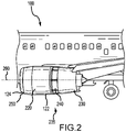
FIG. 2 illustrates a side view of the aircraft ofFIG. 1 including a nacelle in accordance with various embodiments; -
FIG. 3 illustrates a perspective view of a gooseneck hinge assembly for use in a nacelle in accordance with various embodiments; and -
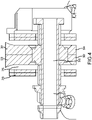
FIG. 4 illustrates a cross-sectional view of the gooseneck hinge assembly ofFIG. 3 in accordance with various embodiments. - The detailed description of various embodiments herein makes reference to the accompanying drawings, which show various embodiments by way of illustration. While these various embodiments are described in sufficient detail to enable those skilled in the art to practice the inventions, it should be understood that other embodiments may be realized and that logical, chemical and mechanical changes may be made without departing from the spirit and scope of the inventions. Thus, the detailed description herein is presented for purposes of illustration only and not of limitation. For example, the steps recited in any of the method or process descriptions may be executed in any order and are not necessarily limited to the order presented.
- Furthermore, any reference to singular includes plural embodiments, and any reference to more than one component or step may include a singular embodiment or step. Also, any reference to attached, fixed, connected or the like may include permanent, removable, temporary, partial, full and/or any other possible attachment option. Additionally, any reference to without contact (or similar phrases) may also include reduced contact or minimal contact.
- In various embodiments and with reference to
FIG. 1 , anaircraft 100 may comprise afuselage 112 and a pair ofwings 114. A propulsion system 120 (e.g., a turbofan gas turbine engine with a nacelle assembly) may be coupled to the aircraft 100 (e.g., mounted on the underside of a wing 114). Thepropulsion system 120 may be configured to provide at least one of forward thrust or propulsion for theaircraft 100. - In various embodiments, the
propulsion system 120 may comprise an engine including afan 118 and anengine core 116, housed within anacelle assembly 122. With reference toFIGS. 1 and2 , the typical nacelle assembly, or more simply anacelle assembly 122, may comprise aninlet 124, afan cowl 220, athrust reverser 235, and an exhaust system. Thenacelle assembly 122 surrounds theengine core 116 providing smooth aerodynamic surfaces for airflow around and into the engine. The nacelle also helps define a bypass air duct through thepropulsion system 120. - The
inlet 124 has acenter 128 and adiameter 126 that extends through the center. The diameter of theinlet 124 may be, for example, between 60 inches (1.52 meters (m)) and 120 inches (3 m), between 70 inches (1.8 m) and 90 inches (2.3 m), or about 80 inches (2.0 m). However, one skilled in the art will realize that anydiameter 126 may be present without departing from the scope of the present disclosure. - In various embodiments, the
fan 118 may draw and direct a flow of air into and through thepropulsion system 120. After thefan 118, the air is divided into two principal flow paths, one flow path through engine core 116 (i.e., a "core airflow"), and another flow path through a bypass air duct (i.e., a "bypass airflow"). The engine core flow path is directed into theengine core 116 and initially passes through a compressor that increases the air flow pressure, and then through a combustor where the air is mixed with fuel and ignited. The combustion of the fuel and air mixture causes a series of turbine blades at the rear of theengine core 116 to rotate, and to drive the engine's compressor andfan 118. The highpressure exhaust gases from the combustion of the fuel and air mixture are thereafter directed through an exhaust system aft of the engine for thrust. - In various embodiments and with reference to
FIG. 2 , athrust reverser system 235 of theaircraft 100 may be included in thenacelle assembly 122 and may include a translatingsleeve 230 and a cascade, or cascade array, 240. Thenacelle assembly 122 may include anaxis 260. Thethrust reverser system 235 may also comprise an air diversion system that is configured to direct airflow in the bypass duct through the cascade to create reverse thrust. The air diversion system may be any suitable system including, for example, blocker doors, diversion doors, and/or the like. - Referring now to
FIGS. 3 and4 , agooseneck hinge assembly 300 may be used between two panels (e.g., afirst panel 324 and a second panel 326) of a portion of thenacelle assembly 122 ofFIG. 1 , such as thefan cowl 220 ofFIG. 2 to allow rotation of a first panel relative to a second panel. In various embodiments, thegooseneck hinge assembly 300 may be used between any two surfaces to facilitate rotation of a first surface relative to a second surface. Unlike conventional hinges, thegooseneck hinge assembly 300 provides redundancy should a portion of thegooseneck hinge assembly 300 become inoperable, as described below. - The
gooseneck hinge assembly 300 includes a firstgooseneck hinge portion 302 and a secondgooseneck hinge portion 304 which is a mirror image of the firstgooseneck hinge portion 302. Each of theportions first end 306 and asecond end 308 with agooseneck curve 312 therebetween. Thesecond end 308 defines anaperture 310 for receiving apin 314. Theportions flange 320 designed to be coupled to a surface. In various embodiments, theflange 320 may be located closer to thefirst end 306 than thesecond end 308. - In various embodiments, the
portions portions portions - The
gooseneck hinge assembly 300 further includes a receivingattachment 316 that defines aU-shaped slot 318 extending along at least a portion thereof in a direction parallel to a longitudinal axis of theportions attachment 316 may further include aflange 322 designed to be coupled to a surface. - As referenced above, the
assembly 300 may be utilized in a nacelle. In that regard, thegooseneck hinge assembly 300 may facilitate rotation of a first surface (such as a first panel 324) relative to a second surface (such as a second panel 326). Thepanels first panel 324 may rotate away from thesecond panel 326 to provide access to an interior of the nacelle (e.g., where theassembly 300 is located) for various reasons. - The first ends 306 of the
gooseneck hinge portions first panel 324. For example, the first ends 306 may be coupled to thefirst panel 324 at theflanges 320. In various embodiments, thefirst panel 324 may include a bump-up 328 onto which theflanges 320 are fastened, such as by use of fasteners or the like. - The receiving
attachment 316 may be coupled to thesecond panel 326, for example, by coupling theflange 322 to thesecond panel 326. In various embodiments, thesecond panel 326 may include a bump-up 330 onto which theflange 322 is fastened, such as by use of fasteners or the like. In various embodiments, the bump-ups - The second ends 308 of the
gooseneck hinge portions attachment 316 via thepin 314. For example, the second ends 308 of thegooseneck hinge portions U-shaped slot 318 such that theapertures 310 of theportions apertures 332 of the receivingattachment 316. Thepin 314 may then be inserted through theapertures gooseneck hinge portions attachment 316. Because the receivingattachment 316 is fastened to thesecond panel 326 and thegooseneck portions first panel 324, this rotatable coupling of thegooseneck portions attachment 316 thus rotatably couples thefirst panel 324 to thesecond panel 326. - The gooseneck curves 312 result in the second ends 308 of the
gooseneck portions U-shaped slot 318 in response to thefirst panel 324 being rotated towards thesecond panel 326. That is, in response to rotation of thefirst panel 324 towards thesecond panel 326, a portion of thegooseneck portions 302, 304 (e.g., a portion between the second ends 308 and the gooseneck curves 312) may be received by theU-shaped slot 318. In that regard, the gooseneck curves 312 result in thegooseneck hinge assembly 300 facilitating rotation of thefirst panel 324 relative to thesecond panel 326 without any portion of thefirst panel 324 or thesecond panel 326 being cut out to facilitate any hinge portion. This desirably increases surface coverage of thepanels - In various embodiments, one or both of the
gooseneck portions respective gooseneck portion respective gooseneck portion gooseneck hinge assembly 300. - Because the
gooseneck portions gooseneck portions first panel 324 relative to thesecond panel 326 due to the remainingnon-failed gooseneck portion gooseneck portion - In the detailed description herein, references to "one embodiment", "an embodiment", "various embodiments", etc., indicate that the embodiment described may include a particular feature, structure, or characteristic, but every embodiment may not necessarily include the particular feature, structure, or characteristic. Moreover, such phrases are not necessarily referring to the same embodiment. Further, when a particular feature, structure, or characteristic is described in connection with an embodiment, it is submitted that it is within the knowledge of one skilled in the art to affect such feature, structure, or characteristic in connection with other embodiments whether or not explicitly described. After reading the description, it will be apparent to one skilled in the relevant art(s) how to implement the disclosure in alternative embodiments.
- Benefits, other advantages, and solutions to problems have been described herein with regard to specific embodiments. Furthermore, the connecting lines shown in the various figures contained herein are intended to represent various functional relationships and/or physical couplings between the various elements. It should be noted that many alternative or additional functional relationships or physical connections may be present in a practical system. However, the benefits, advantages, solutions to problems, and any elements that may cause any benefit, advantage, or solution to occur or become more pronounced are not to be construed as critical, required, or essential features or elements of the inventions. The scope of the inventions is accordingly to be limited by nothing other than the appended claims, in which reference to an element in the singular is not intended to mean "one and only one" unless explicitly so stated, but rather "one or more." Moreover, where a phrase similar to "at least one of A, B, or C" is used in the claims, it is intended that the phrase be interpreted to mean that A alone may be present in an embodiment, B alone may be present in an embodiment, C alone may be present in an embodiment, or that any combination of the elements A, B and C may be present in a single embodiment; for example, A and B, A and C, B and C, or A and B and C. Different cross-hatching is used throughout the figures to denote different parts but not necessarily to denote the same or different materials.
- Furthermore, no element, component, or method step in the present disclosure is intended to be dedicated to the public regardless of whether the element, component, or method step is explicitly recited in the claims. As used herein, the terms "comprises", "comprising", or any other variation thereof, are intended to cover a non-exclusive inclusion, such that a process, method, article, or apparatus that comprises a list of elements does not include only those elements but may include other elements not expressly listed or inherent to such process, method, article, or apparatus.
Claims (11)
- A gooseneck hinge assembly (300), comprising:a first gooseneck hinge portion (302) having a first portion first end (306) configured to be coupled to a first surface (324), a first portion second end (308) having a first portion aperture (310) configured to receive a pin (314), and a first gooseneck curve (312) between the first portion first end (306) and the first portion second end (308);a second gooseneck hinge portion (304) being a mirror image of the first gooseneck hinge portion (302) and having a second portion first end (306) configured to be coupled to the first surface (324), a second portion second end (308) having a second portion aperture (310) configured to receive the pin (314), and a second gooseneck curve (312) between the second portion first end (306) and the second portion second end (308); andthe pin (314) coupled to a second surface (326) and configured to extend through the first portion aperture (310) and the second portion aperture (310) to facilitate rotation of the second surface (326) relative to the first surface (324).
- The gooseneck hinge assembly (300) of claim 1, wherein the first gooseneck hinge portion (302) defines a first portion flange (320) configured to extend parallel to the first surface (324) and to be coupled to the first surface (324), and the second gooseneck hinge portion (304) defines a second portion flange (320) configured to extend away from the first portion flange (320), to extend parallel to the first surface (324), and to be coupled to the first surface (324).
- The gooseneck hinge assembly (300) of claim 2, wherein the first surface (324) defines a bump-up (328), the first portion flange (320) configured to be coupled to the bump-up (328), and the second portion flange (320) configured to be coupled to the bump-up (328).
- The gooseneck hinge assembly (300) of claim 1, 2, or 3, further comprising a receiving attachment (316) configured to be coupled to the second surface (326) and defining a U-shaped slot (318) for receiving the first portion second end (308) and the second portion second end (308) such that the pin (314) extends through the receiving attachment (316), the first portion aperture (310), and the second portion aperture (310).
- The gooseneck hinge assembly (300) of claim 4, wherein the receiving attachment (316) further includes a receiving flange (322) extending parallel to the second surface (326) and configured to be coupled to the second surface (326).
- The gooseneck hinge assembly (300) of claim 4 or 5, wherein the first gooseneck hinge portion (302), the second gooseneck hinge portion (304), and the receiving attachment (316) are each composed in part of a metallic material.
- The gooseneck hinge assembly (300) of claim 4, 5, or 6, wherein the U-shaped slot (318) is configured to receive a portion of the first gooseneck curve (312) and the second gooseneck curve (312) in response to the rotation of the second surface (326) relative to the first surface (324).
- The gooseneck hinge assembly (300) of any preceding claim, wherein the gooseneck hinge assembly (300) is configured for use with a nacelle (122), for example of an aircraft (100).
- The gooseneck hinge assembly (300) of claim 8, wherein the first surface (324) is a first composite panel (324) of the nacelle (122) and the second surface (326) is a second composite panel (326) of the nacelle (122).
- The gooseneck hinge assembly (300) of claim 9, wherein at least one of the first panel (324) or the second panel (326) is a portion of a fan cowl (220) of the nacelle (122).
- The gooseneck hinge assembly (300) of any preceding claim, wherein the first surface (324) is a first panel (324) and the second surface (326) is a second panel (326).
Applications Claiming Priority (1)
| Application Number | Priority Date | Filing Date | Title |
|---|---|---|---|
| US17/133,351 US11384660B1 (en) | 2020-12-23 | 2020-12-23 | Fan cowl failsafe gooseneck assembly |
Publications (2)
| Publication Number | Publication Date |
|---|---|
| EP4019407A1 true EP4019407A1 (en) | 2022-06-29 |
| EP4019407B1 EP4019407B1 (en) | 2025-02-12 |
Family
ID=79283194
Family Applications (1)
| Application Number | Title | Priority Date | Filing Date |
|---|---|---|---|
| EP21216399.2A Active EP4019407B1 (en) | 2020-12-23 | 2021-12-21 | Fan cowl failsafe gooseneck assembly |
Country Status (2)
| Country | Link |
|---|---|
| US (1) | US11384660B1 (en) |
| EP (1) | EP4019407B1 (en) |
Citations (2)
| Publication number | Priority date | Publication date | Assignee | Title |
|---|---|---|---|---|
| US20130042435A1 (en) * | 2011-08-19 | 2013-02-21 | Midway Products Group, Inc. | Hinge assembly |
| US20200172255A1 (en) * | 2018-12-04 | 2020-06-04 | Goodrich Corporation | Guided fan cowl hinge |
Family Cites Families (11)
| Publication number | Priority date | Publication date | Assignee | Title |
|---|---|---|---|---|
| US4854010A (en) * | 1987-11-20 | 1989-08-08 | The Boeing Company | Hinge mechanism for aircraft door |
| FR2661213B1 (en) * | 1990-04-19 | 1992-07-03 | Snecma | AVIATION ENGINE WITH VERY HIGH DILUTION RATES AND OF THE SAID TYPE FRONT CONTRAFAN. |
| FR2768489B1 (en) * | 1997-09-12 | 1999-11-19 | Eurocopter France | ARTICULATED HOOK PANEL |
| US6517027B1 (en) | 2001-12-03 | 2003-02-11 | Pratt & Whitney Canada Corp. | Flexible/fixed support for engine cowl |
| US8439308B2 (en) | 2010-11-19 | 2013-05-14 | The Boeing Company | Spring loaded pressure relief door |
| US9873504B2 (en) * | 2013-10-18 | 2018-01-23 | Rohr, Inc. | Propulsion system nacelle with reduced number of external split lines |
| US9758234B2 (en) | 2015-01-08 | 2017-09-12 | Rohr, Inc. | Quick release hinge |
| US9777522B2 (en) * | 2015-06-09 | 2017-10-03 | Nissan North America, Inc. | Door hinge check structure |
| DE102015226546A1 (en) * | 2015-12-22 | 2017-06-22 | Rolls-Royce Deutschland Ltd & Co Kg | Engine cowling |
| US11280124B2 (en) | 2018-01-16 | 2022-03-22 | The Boeing Company | Locking hinge apparatus for aircraft doors |
| FR3079000A1 (en) | 2018-03-13 | 2019-09-20 | Airbus Operations | DOUBLE FLOW TURBOREACTOR FOR AN AIRCRAFT WITH AN OPENING EQUIPPED WITH A HINGE WITH SWINGLOCK CLAMP |
-
2020
- 2020-12-23 US US17/133,351 patent/US11384660B1/en active Active
-
2021
- 2021-12-21 EP EP21216399.2A patent/EP4019407B1/en active Active
Patent Citations (2)
| Publication number | Priority date | Publication date | Assignee | Title |
|---|---|---|---|---|
| US20130042435A1 (en) * | 2011-08-19 | 2013-02-21 | Midway Products Group, Inc. | Hinge assembly |
| US20200172255A1 (en) * | 2018-12-04 | 2020-06-04 | Goodrich Corporation | Guided fan cowl hinge |
Also Published As
| Publication number | Publication date |
|---|---|
| US20220195890A1 (en) | 2022-06-23 |
| EP4019407B1 (en) | 2025-02-12 |
| US11384660B1 (en) | 2022-07-12 |
Similar Documents
| Publication | Publication Date | Title |
|---|---|---|
| EP3705711B1 (en) | Hidden link system blocker door | |
| US9714627B2 (en) | Mounting of aircraft propulsion system outer sleeve and inner structure to pylon with distinct hinges | |
| EP3549856B1 (en) | Fan cowl latch concept for fuselage mounted power plant | |
| US20200003152A1 (en) | Target door reverser with non-parallel hinge lines | |
| US11053887B2 (en) | Thrust reverser with displaceable trailing edge body | |
| US11548652B2 (en) | Nacelle | |
| US10724474B2 (en) | Hybrid articulating/translating trailing edge reverser | |
| EP3326916B1 (en) | Nacelle latch alignment | |
| EP3546735B1 (en) | Hybrid pivot door thrust reversers | |
| EP3712073A1 (en) | Self-engaging fan cowl hook latch | |
| EP4019407B1 (en) | Fan cowl failsafe gooseneck assembly | |
| US11566585B2 (en) | Synchronization mechanism for pivot door thrust reversers | |
| US10995701B2 (en) | Translating sleeve thrust reverser assembly | |
| EP4257481A1 (en) | Nacelle inlet structure fitting with locator clip and hoist bracket | |
| EP3663207B1 (en) | Guided fan cowl hinge | |
| EP3733525B1 (en) | Fan cowl securement retainers | |
| US11731774B2 (en) | Dual axis hinge radial displacement limiter |
Legal Events
| Date | Code | Title | Description |
|---|---|---|---|
| PUAI | Public reference made under article 153(3) epc to a published international application that has entered the european phase |
Free format text: ORIGINAL CODE: 0009012 |
|
| STAA | Information on the status of an ep patent application or granted ep patent |
Free format text: STATUS: THE APPLICATION HAS BEEN PUBLISHED |
|
| AK | Designated contracting states |
Kind code of ref document: A1 Designated state(s): AL AT BE BG CH CY CZ DE DK EE ES FI FR GB GR HR HU IE IS IT LI LT LU LV MC MK MT NL NO PL PT RO RS SE SI SK SM TR |
|
| STAA | Information on the status of an ep patent application or granted ep patent |
Free format text: STATUS: REQUEST FOR EXAMINATION WAS MADE |
|
| STAA | Information on the status of an ep patent application or granted ep patent |
Free format text: STATUS: EXAMINATION IS IN PROGRESS |
|
| 17P | Request for examination filed |
Effective date: 20221229 |
|
| RBV | Designated contracting states (corrected) |
Designated state(s): AL AT BE BG CH CY CZ DE DK EE ES FI FR GB GR HR HU IE IS IT LI LT LU LV MC MK MT NL NO PL PT RO RS SE SI SK SM TR |
|
| 17Q | First examination report despatched |
Effective date: 20230127 |
|
| GRAP | Despatch of communication of intention to grant a patent |
Free format text: ORIGINAL CODE: EPIDOSNIGR1 |
|
| STAA | Information on the status of an ep patent application or granted ep patent |
Free format text: STATUS: GRANT OF PATENT IS INTENDED |
|
| INTG | Intention to grant announced |
Effective date: 20240906 |
|
| GRAS | Grant fee paid |
Free format text: ORIGINAL CODE: EPIDOSNIGR3 |
|
| GRAA | (expected) grant |
Free format text: ORIGINAL CODE: 0009210 |
|
| STAA | Information on the status of an ep patent application or granted ep patent |
Free format text: STATUS: THE PATENT HAS BEEN GRANTED |
|
| AK | Designated contracting states |
Kind code of ref document: B1 Designated state(s): AL AT BE BG CH CY CZ DE DK EE ES FI FR GB GR HR HU IE IS IT LI LT LU LV MC MK MT NL NO PL PT RO RS SE SI SK SM TR |
|
| REG | Reference to a national code |
Ref country code: GB Ref legal event code: FG4D |
|
| REG | Reference to a national code |
Ref country code: CH Ref legal event code: EP |
|
| REG | Reference to a national code |
Ref country code: DE Ref legal event code: R096 Ref document number: 602021025954 Country of ref document: DE |
|
| REG | Reference to a national code |
Ref country code: IE Ref legal event code: FG4D |
|
| REG | Reference to a national code |
Ref country code: NL Ref legal event code: MP Effective date: 20250212 |
|
| PG25 | Lapsed in a contracting state [announced via postgrant information from national office to epo] |
Ref country code: RS Free format text: LAPSE BECAUSE OF FAILURE TO SUBMIT A TRANSLATION OF THE DESCRIPTION OR TO PAY THE FEE WITHIN THE PRESCRIBED TIME-LIMIT Effective date: 20250512 |
|
| PG25 | Lapsed in a contracting state [announced via postgrant information from national office to epo] |
Ref country code: FI Free format text: LAPSE BECAUSE OF FAILURE TO SUBMIT A TRANSLATION OF THE DESCRIPTION OR TO PAY THE FEE WITHIN THE PRESCRIBED TIME-LIMIT Effective date: 20250212 |
|
| PG25 | Lapsed in a contracting state [announced via postgrant information from national office to epo] |
Ref country code: PL Free format text: LAPSE BECAUSE OF FAILURE TO SUBMIT A TRANSLATION OF THE DESCRIPTION OR TO PAY THE FEE WITHIN THE PRESCRIBED TIME-LIMIT Effective date: 20250212 |
|
| PG25 | Lapsed in a contracting state [announced via postgrant information from national office to epo] |
Ref country code: ES Free format text: LAPSE BECAUSE OF FAILURE TO SUBMIT A TRANSLATION OF THE DESCRIPTION OR TO PAY THE FEE WITHIN THE PRESCRIBED TIME-LIMIT Effective date: 20250212 |
|
| REG | Reference to a national code |
Ref country code: LT Ref legal event code: MG9D |
|
| PG25 | Lapsed in a contracting state [announced via postgrant information from national office to epo] |
Ref country code: NO Free format text: LAPSE BECAUSE OF FAILURE TO SUBMIT A TRANSLATION OF THE DESCRIPTION OR TO PAY THE FEE WITHIN THE PRESCRIBED TIME-LIMIT Effective date: 20250512 Ref country code: IS Free format text: LAPSE BECAUSE OF FAILURE TO SUBMIT A TRANSLATION OF THE DESCRIPTION OR TO PAY THE FEE WITHIN THE PRESCRIBED TIME-LIMIT Effective date: 20250612 |
|
| PG25 | Lapsed in a contracting state [announced via postgrant information from national office to epo] |
Ref country code: NL Free format text: LAPSE BECAUSE OF FAILURE TO SUBMIT A TRANSLATION OF THE DESCRIPTION OR TO PAY THE FEE WITHIN THE PRESCRIBED TIME-LIMIT Effective date: 20250212 |
|
| PG25 | Lapsed in a contracting state [announced via postgrant information from national office to epo] |
Ref country code: HR Free format text: LAPSE BECAUSE OF FAILURE TO SUBMIT A TRANSLATION OF THE DESCRIPTION OR TO PAY THE FEE WITHIN THE PRESCRIBED TIME-LIMIT Effective date: 20250212 |
|
| PG25 | Lapsed in a contracting state [announced via postgrant information from national office to epo] |
Ref country code: PT Free format text: LAPSE BECAUSE OF FAILURE TO SUBMIT A TRANSLATION OF THE DESCRIPTION OR TO PAY THE FEE WITHIN THE PRESCRIBED TIME-LIMIT Effective date: 20250612 Ref country code: LV Free format text: LAPSE BECAUSE OF FAILURE TO SUBMIT A TRANSLATION OF THE DESCRIPTION OR TO PAY THE FEE WITHIN THE PRESCRIBED TIME-LIMIT Effective date: 20250212 |
|
| PG25 | Lapsed in a contracting state [announced via postgrant information from national office to epo] |
Ref country code: GR Free format text: LAPSE BECAUSE OF FAILURE TO SUBMIT A TRANSLATION OF THE DESCRIPTION OR TO PAY THE FEE WITHIN THE PRESCRIBED TIME-LIMIT Effective date: 20250513 Ref country code: BG Free format text: LAPSE BECAUSE OF FAILURE TO SUBMIT A TRANSLATION OF THE DESCRIPTION OR TO PAY THE FEE WITHIN THE PRESCRIBED TIME-LIMIT Effective date: 20250212 |
|
| REG | Reference to a national code |
Ref country code: AT Ref legal event code: MK05 Ref document number: 1765874 Country of ref document: AT Kind code of ref document: T Effective date: 20250212 |
|
| PG25 | Lapsed in a contracting state [announced via postgrant information from national office to epo] |
Ref country code: SE Free format text: LAPSE BECAUSE OF FAILURE TO SUBMIT A TRANSLATION OF THE DESCRIPTION OR TO PAY THE FEE WITHIN THE PRESCRIBED TIME-LIMIT Effective date: 20250212 |
|
| PG25 | Lapsed in a contracting state [announced via postgrant information from national office to epo] |
Ref country code: SM Free format text: LAPSE BECAUSE OF FAILURE TO SUBMIT A TRANSLATION OF THE DESCRIPTION OR TO PAY THE FEE WITHIN THE PRESCRIBED TIME-LIMIT Effective date: 20250212 |
|
| PG25 | Lapsed in a contracting state [announced via postgrant information from national office to epo] |
Ref country code: DK Free format text: LAPSE BECAUSE OF FAILURE TO SUBMIT A TRANSLATION OF THE DESCRIPTION OR TO PAY THE FEE WITHIN THE PRESCRIBED TIME-LIMIT Effective date: 20250212 |
|
| PG25 | Lapsed in a contracting state [announced via postgrant information from national office to epo] |
Ref country code: IT Free format text: LAPSE BECAUSE OF FAILURE TO SUBMIT A TRANSLATION OF THE DESCRIPTION OR TO PAY THE FEE WITHIN THE PRESCRIBED TIME-LIMIT Effective date: 20250212 |
|
| PG25 | Lapsed in a contracting state [announced via postgrant information from national office to epo] |
Ref country code: AT Free format text: LAPSE BECAUSE OF FAILURE TO SUBMIT A TRANSLATION OF THE DESCRIPTION OR TO PAY THE FEE WITHIN THE PRESCRIBED TIME-LIMIT Effective date: 20250212 |
|
| PG25 | Lapsed in a contracting state [announced via postgrant information from national office to epo] |
Ref country code: EE Free format text: LAPSE BECAUSE OF FAILURE TO SUBMIT A TRANSLATION OF THE DESCRIPTION OR TO PAY THE FEE WITHIN THE PRESCRIBED TIME-LIMIT Effective date: 20250212 Ref country code: CZ Free format text: LAPSE BECAUSE OF FAILURE TO SUBMIT A TRANSLATION OF THE DESCRIPTION OR TO PAY THE FEE WITHIN THE PRESCRIBED TIME-LIMIT Effective date: 20250212 |
|
| PG25 | Lapsed in a contracting state [announced via postgrant information from national office to epo] |
Ref country code: RO Free format text: LAPSE BECAUSE OF FAILURE TO SUBMIT A TRANSLATION OF THE DESCRIPTION OR TO PAY THE FEE WITHIN THE PRESCRIBED TIME-LIMIT Effective date: 20250212 |
|
| PG25 | Lapsed in a contracting state [announced via postgrant information from national office to epo] |
Ref country code: SK Free format text: LAPSE BECAUSE OF FAILURE TO SUBMIT A TRANSLATION OF THE DESCRIPTION OR TO PAY THE FEE WITHIN THE PRESCRIBED TIME-LIMIT Effective date: 20250212 |
|
| REG | Reference to a national code |
Ref country code: DE Ref legal event code: R097 Ref document number: 602021025954 Country of ref document: DE |
|
| PLBE | No opposition filed within time limit |
Free format text: ORIGINAL CODE: 0009261 |
|
| STAA | Information on the status of an ep patent application or granted ep patent |
Free format text: STATUS: NO OPPOSITION FILED WITHIN TIME LIMIT |
|
| PGFP | Annual fee paid to national office [announced via postgrant information from national office to epo] |
Ref country code: DE Payment date: 20251126 Year of fee payment: 5 |
|
| PGFP | Annual fee paid to national office [announced via postgrant information from national office to epo] |
Ref country code: GB Payment date: 20251120 Year of fee payment: 5 |
|
| PGFP | Annual fee paid to national office [announced via postgrant information from national office to epo] |
Ref country code: FR Payment date: 20251120 Year of fee payment: 5 |
|
| 26N | No opposition filed |
Effective date: 20251113 |