EP4019393A1 - Outboard motor - Google Patents
Outboard motor Download PDFInfo
- Publication number
- EP4019393A1 EP4019393A1 EP21201678.6A EP21201678A EP4019393A1 EP 4019393 A1 EP4019393 A1 EP 4019393A1 EP 21201678 A EP21201678 A EP 21201678A EP 4019393 A1 EP4019393 A1 EP 4019393A1
- Authority
- EP
- European Patent Office
- Prior art keywords
- case
- case part
- outboard motor
- engine
- parts
- Prior art date
- Legal status (The legal status is an assumption and is not a legal conclusion. Google has not performed a legal analysis and makes no representation as to the accuracy of the status listed.)
- Pending
Links
Images



Classifications
-
- B—PERFORMING OPERATIONS; TRANSPORTING
- B63—SHIPS OR OTHER WATERBORNE VESSELS; RELATED EQUIPMENT
- B63H—MARINE PROPULSION OR STEERING
- B63H20/00—Outboard propulsion units, e.g. outboard motors or Z-drives; Arrangements thereof on vessels
- B63H20/32—Housings
-
- B—PERFORMING OPERATIONS; TRANSPORTING
- B63—SHIPS OR OTHER WATERBORNE VESSELS; RELATED EQUIPMENT
- B63H—MARINE PROPULSION OR STEERING
- B63H20/00—Outboard propulsion units, e.g. outboard motors or Z-drives; Arrangements thereof on vessels
- B63H20/001—Arrangements, apparatus and methods for handling fluids used in outboard drives
- B63H20/002—Arrangements, apparatus and methods for handling fluids used in outboard drives for handling lubrication liquids
-
- B—PERFORMING OPERATIONS; TRANSPORTING
- B63—SHIPS OR OTHER WATERBORNE VESSELS; RELATED EQUIPMENT
- B63H—MARINE PROPULSION OR STEERING
- B63H20/00—Outboard propulsion units, e.g. outboard motors or Z-drives; Arrangements thereof on vessels
- B63H20/02—Mounting of propulsion units
-
- B—PERFORMING OPERATIONS; TRANSPORTING
- B63—SHIPS OR OTHER WATERBORNE VESSELS; RELATED EQUIPMENT
- B63H—MARINE PROPULSION OR STEERING
- B63H20/00—Outboard propulsion units, e.g. outboard motors or Z-drives; Arrangements thereof on vessels
- B63H20/08—Means enabling movement of the position of the propulsion element, e.g. for trim, tilt or steering; Control of trim or tilt
-
- B—PERFORMING OPERATIONS; TRANSPORTING
- B63—SHIPS OR OTHER WATERBORNE VESSELS; RELATED EQUIPMENT
- B63H—MARINE PROPULSION OR STEERING
- B63H20/00—Outboard propulsion units, e.g. outboard motors or Z-drives; Arrangements thereof on vessels
- B63H20/08—Means enabling movement of the position of the propulsion element, e.g. for trim, tilt or steering; Control of trim or tilt
- B63H20/10—Means enabling trim or tilt, or lifting of the propulsion element when an obstruction is hit; Control of trim or tilt
-
- B—PERFORMING OPERATIONS; TRANSPORTING
- B63—SHIPS OR OTHER WATERBORNE VESSELS; RELATED EQUIPMENT
- B63H—MARINE PROPULSION OR STEERING
- B63H20/00—Outboard propulsion units, e.g. outboard motors or Z-drives; Arrangements thereof on vessels
- B63H20/08—Means enabling movement of the position of the propulsion element, e.g. for trim, tilt or steering; Control of trim or tilt
- B63H20/12—Means enabling steering
-
- B—PERFORMING OPERATIONS; TRANSPORTING
- B63—SHIPS OR OTHER WATERBORNE VESSELS; RELATED EQUIPMENT
- B63H—MARINE PROPULSION OR STEERING
- B63H20/00—Outboard propulsion units, e.g. outboard motors or Z-drives; Arrangements thereof on vessels
- B63H20/14—Transmission between propulsion power unit and propulsion element
-
- B—PERFORMING OPERATIONS; TRANSPORTING
- B63—SHIPS OR OTHER WATERBORNE VESSELS; RELATED EQUIPMENT
- B63H—MARINE PROPULSION OR STEERING
- B63H23/00—Transmitting power from propulsion power plant to propulsive elements
- B63H23/32—Other parts
- B63H23/34—Propeller shafts; Paddle-wheel shafts; Attachment of propellers on shafts
Definitions
- the present invention relates to an outboard motor.
- outboard motors There are conventional outboard motors known in the art that include a propulsion unit having a propeller, an engine that drives the propulsion unit, and a drive shaft that transmits the power of the engine to the propulsion unit (see, for example, JP A 2009-160970 ).
- the engine is arranged upward of the propulsion unit and is covered by a cover.
- a case is provided between the engine and the propulsion unit.
- the engine is secured to an upper portion of the case, and the propulsion unit is secured to a lower portion of the case.
- the engine and the propulsion unit are supported on the case.
- the drive shaft extends downward from the engine.
- the propulsion unit is connected to the lower end portion of the drive shaft.
- the case receives a load from the engine and the propulsion unit.
- the case is a part that serves the role as a frame for stably supporting the engine and the propulsion unit, and needs to have a sufficient mechanical strength. Since the case is arranged between the engine and the propulsion unit, the case serves the role of guiding the drive shaft extending downward from the engine toward the propulsion unit. Therefore, the case is formed in a tubular shape so as to surround the drive shaft. With conventional outboard motors, the case is manufactured by casting.
- the dimension of the case in the up-down direction is large.
- casting it is difficult to manufacture a case having a large dimension in the up-down direction. Therefore, in order to manufacture a case having a large dimension in the up-down direction, it is necessary to manufacture an upper case part and a lower case part by casting and then assemble them together. This, however, results in a problem that the upper and lower case parts each need to have a flange for the assembly, thereby increasing the weight of the case.
- An outboard motor disclosed herein includes: an engine; a propulsion unit arranged downward of the engine and including a propeller; a drive shaft connected to the engine and the propulsion unit so as to transmit a drive force from the engine to the propulsion unit; and a case arranged between the engine and the propulsion unit.
- the case includes an engine attachment portion to which the engine is attached and a propulsion unit attachment portion to which the propulsion unit is attached.
- the case is composed of a plurality of case parts that are formed separately from each other and assembled together.
- the case parts include a first case part and a second case part opposing each other in a direction perpendicular to an axis of the drive shaft.
- the case is obtained by assembling together a plurality of case parts.
- the case parts each have a relatively simple and small configuration. Therefore, it is possible to relatively easily manufacture the case even when the case has a complicated or large configuration.
- the case parts include a first case part and a second case part that oppose each other in the direction perpendicular to the axis of the drive shaft.
- the first case part and the second case part are assembled on top of each other, they need to have a flange, which leads to an increase in weight, but there is no need for such a flange. Therefore, with the outboard motor described above, even when the upper case has a complicated or large configuration, it is possible to prevent an increase in weight while ensuring a sufficient mechanical strength.
- an outboard motor that can be easily manufactured while ensuring a sufficient mechanical strength and preventing an increase in weight even when the case has a complicated or large-sized configuration.
- FIG. 1 shows a watercraft 10 including an outboard motor 100 according to the present embodiment.
- the watercraft 10 includes the hull 11, a steering wheel 12, a remote controller 13 and the outboard motor 100.
- the outboard motor 100 is attached to the rear portion of the hull 11.
- the steering wheel 12 is provided for steering the hull 11.
- the outboard motor 100 rotates leftward or rightward relative to the hull 11. It is possible to shift gears of the outboard motor 100.
- the remote controller 13 By operating the remote controller 13, the passenger can switch the state of the outboard motor 100 between forward, backward and neutral.
- the outboard motor 100 includes an engine 1, and the engine 1 is provided with a throttle valve (not shown). By operating the remote controller 13, the passenger can adjust the opening of the throttle valve. By adjusting the opening of the throttle valve, it is possible to adjust the output power of the outboard motor 100.
- FIG. 2 is a side view showing the outboard motor 100.
- the outboard motor 100 includes an outboard motor main unit 101, a support member 50 for supporting the outboard motor main unit 101, and an attachment member 70 for attaching the support member 50 to the hull 11.
- the outboard motor main unit 101 includes the engine 1, a propulsion unit 5 including a propeller 3, the drive shaft 7 connected to the engine 1 and the propulsion unit 5, and an upper case 20.
- the upper case 20 is arranged between the engine 1 and the propulsion unit 5.
- the engine 1 is arranged upward of the upper case 20.
- the propulsion unit 5 is arranged downward of the upper case 20 and is arranged downward of the engine 1.
- the engine 1 is an internal combustion engine that is driven through combustion of fuel such as gasoline or diesel oil.
- the engine 1 is covered by a cover 2.
- the drive shaft 7 is configured to transmit power output from the engine 1 to the propulsion unit 5.
- the drive shaft 7 extends downward from the engine 1.
- the drive shaft 7 rotates by being driven by the engine 1.
- the propulsion unit 5 includes a propeller shaft 9 on which the propeller 3 is provided, a gear device 15 that links together the drive shaft 7 and the propeller shaft 9, and a lower case 6.
- the gear device 15 transmits the rotation of the drive shaft 7 to the propeller shaft 9 while decelerating the rotation.
- the gear device 15 includes a pinion gear, a forward bevel gear, a backward bevel gear and a dog clutch.
- a gear device well known in the art can be suitably used as the gear device 15.
- the propeller 3 rotates together with the propeller shaft 9, thereby generating forward or backward propulsion.
- the upper case 20 is composed of a plurality of case parts 21 to 26 to be described below. These case parts 21 to 26 are formed separately from each other. That is, the case parts 21 to 26 are separate parts.
- the upper case 20 includes an upper plate part 25 and a lower plate part 26 as case parts.
- the upper plate part 25 and the lower plate part 26 are each formed in a horizontal plate shape. Note however that there is no particular limitation on the shape of the upper plate part 25 and the lower plate part 26.
- the upper plate part 25 and the lower plate part 26 extend in the left-right direction and in the front-rear direction.
- the engine 1 is attached to the upper plate part 25.
- the upper plate part 25 is an example of the "engine attachment portion" to which the engine 1 is attached.
- a propulsion unit 6 is attached to the lower plate part 26.
- the lower plate part 26 is an example of the "propulsion unit attachment portion" to which the propulsion unit 6 is attached.
- the upper case 20 includes, as case parts, a first case part 21 and a second case part 22 that oppose each other in the direction perpendicular to the axis 7c of the drive shaft 7.
- the first case part 21 and the second case part 22 each extend in the up-down direction.
- the first case part 21 and the second case part 22 each extend in the front-rear direction.
- the drive shaft 7 is arranged between the first case part 21 and the second case part 22.
- the second case part 22 is arranged rightward of the first case part 21.
- the first case part 21 is arranged leftward of the drive shaft 7, and the second case part 22 is arranged rightward of the drive shaft 7.
- FIG. 5 is a front surface view showing the first case part 21, as the first case part 21 is viewed from the left side.
- FIG. 6 is a reverse surface view showing the first case part 21, as the first case part 21 is viewed from the right side.
- the first case part 21 includes a main body 31 having a curved plate shape extending in the up-down direction and the front-rear direction, and a plurality of reinforcement ribs 33 provided on the main body 31.
- the dimension of the first case part 21 in the up-down direction is larger than that in the front-rear direction and larger than that in the left-right direction.
- the reinforcement ribs 33 are provided on the reverse side of the main body 31.
- the reinforcement ribs 33 are each an elongate projection that is protruding from the reverse-side surface of the main body 31.
- the reinforcement ribs 33 include a horizontal rib 33h extending in the horizontal direction, slant ribs 33a, 33b, 33c and 33d extending rearward and downward, a slant rib 33e extending rearward and upward, a vertical rib 33v extending in the vertical direction, and a curved rib 33f that is curved.
- the horizontal rib 33h, the slant rib 33a and the curved rib 33f are provided along the edge of the main body 31.
- the slant ribs 33b, 33c, 33d and 33e and the vertical rib 33v are provided on the inside of the edge of the main body 31.
- the axis 7c of the drive shaft 7 extends in the vertical direction.
- the slant ribs 33a, 33b, 33c, 33d and 33e each extend in a slant direction relative to a direction parallel to the axis 7c of the drive shaft 7.
- the slant ribs 33a, 33b and 33c extend rearward and downward. In other words, a slant ribs 33a, 33b and 33c extend toward the propeller 3 as they extend rearward.
- the horizontal rib 33h extends in a direction perpendicular to a direction parallel to the axis 7c of the drive shaft 7.
- the main body 31 includes through holes 32.
- the through holes 32 are open in a direction perpendicular to the axis 7c of the drive shaft 7.
- the through holes 32 are open leftward and rightward.
- the main body 31 includes three through holes 32.
- the number of through holes 32 may be two or four or more.
- the number of through holes 32 is not limited to more than one, but may be one.
- the through holes 32 are provided so as to reduce the weight of the first case part 21.
- the three through holes 32 are arranged in the up-down direction. Note however that there is no particular limitation on the arrangement of the through holes 32. There is no limitation on the shapes of the through holes 32.
- the second case part 22 has a shape that is in left-right symmetry with the first case part 21. Therefore, elements of the second case part 22 corresponding to those of the first case part 21 are denoted by like reference signs, and the configuration of the second case part 22 will not be described.
- the upper case 20 includes, as case parts, a third case part 23 and a fourth case part 24 connected to the first case part 21 and the second case part 22, respectively.
- the third case part 23 and the fourth case part 24 are provided bridging between the first case part 21 and the second case part 22.
- the third case part 23 and the fourth case part 24 extend in the left-right direction.
- the third case part 23 and the fourth case part 24 extend perpendicular to the first case part 21 and the second case part 22.
- the third case part 23 or the fourth case part 24 may extend slant relative to at least one of the first case part 21 and the second case part 22.
- the fourth case part 24 is arranged upward of the third case part 23.
- the third case part 23 is arranged downward relative to the middle position of the first case part 21 and the second case part 22 in the up-down direction.
- the fourth case part 24 is arranged upward relative to the middle position of the first case part 21 and the second case part 22 in the up-down direction.
- the third case part 23 and the fourth case part 24 each have a hole 37 through which a steering shaft 61, 62 (see FIG. 2 ) to be described below is inserted.
- a first reinforcement member 27 is connected to the first case part 21 and the second case part 22.
- the first reinforcement member 27 is provided bridging between the first case part 21 and the second case part 22.
- the first reinforcement member 27 extends in the left-right direction.
- the first reinforcement member 27 extends perpendicular to the first case part 21 and the second case part 22.
- the first reinforcement member 27 may extend slant relative to at least one of the first case part 21 and the second case part 22.
- the first reinforcement member 27 is arranged upward of the third case part 23 and downward of the fourth case part 24.
- a second reinforcement member 28 is connected to the first case part 21, the second case part 22 and the upper plate part 25.
- the second reinforcement member 28 is formed in a triangular ring shape.
- the second reinforcement member 28 is provided bridging between the first case part 21, the second case part 22 and the upper plate part 25.
- the second reinforcement member 28 is arranged upward relative to the third case part 23.
- the upper case 20 is obtained by assembling together the case parts 21 to 26.
- the case parts 21 to 26 include bolt holes 35.
- the case parts 21 to 26 are assembled together by bolts 36 inserted through these bolt holes 35 (see FIG. 2 ).
- bolts 36 inserted through these bolt holes 35 (see FIG. 2 ).
- Some or all of the case parts 21 to 26 may be attached together by means of fastening devices such as the bolts 36 or may be attached together by welding, or the like, without using fastening devices.
- the case parts 21 to 26 are separate from each other and are manufactured separately. Since the case parts 21 to 26 are separate from each other, the case parts 21 to 26 do not need to use the same material or the same manufacturing method. That is, the case parts 21 to 26 may use the same material or may use different materials.
- the case parts 21 to 26 may include case parts of different materials.
- the case parts 21 to 26 may use the same manufacturing method or may use different manufacturing methods.
- the case parts 21 to 26 may include case parts manufactured by casting and case parts manufactured by forging.
- the first case part 21 and the second case part 22 are made of die-cast aluminum, and are manufactured by casting.
- the third case part 23 and the fourth case part 24 are a heat-treated aluminum forged material, and are manufactured by forging. Note however that the above description is merely illustrative, and there is no limitation on the material and the manufacturing method of the first to fourth case parts 21 to 24.
- the third case part 23 and the fourth case part 24 may be a heat-treated gravity-cast material.
- the mechanical strength of the third case part 23 and the fourth case part 24 is higher than the mechanical strength of the first case part 21 and the second case part 22.
- the outboard motor main unit 101 further includes components such as an exhaust pipe for discharging exhaust gas of the engine 1, an oil tank for storing oil of the engine 1 and a water pump for supplying cooling water to the engine 1.
- the inside of the upper case 20 can be used as a space for installation of these components. Since the upper case 20 is not a closed case, these components can be arranged so as to straddle the inside and the outside of the upper case 20.
- an oil tank 87 and an exhaust pipe 88 may be arranged so as to straddle the inside and the outside of the upper case 20.
- the oil tank 87 includes an inner portion 87i and an outer portion 87o.
- the exhaust pipe 88 includes an inner portion 88i and an outer portion 88o.
- the inner portions 87i and 88i are arranged inside the upper case 20, downward relative to the upper end of the upper case 20 and upward relative to the lower end thereof.
- the inner portions 87i and 88i are arranged downward relative to the upper end of the upper case 20, upward relative to the lower end thereof, rearward relative to the front end thereof and forward relative to the rear end thereof.
- the inner portions 87i and 88i overlap with the upper case 20 as viewed in a side view.
- the outer portions 87o and 88o is located outside the upper case 20, downward relative to the upper end of the upper case 20 and upward relative to the lower end thereof.
- the outer portions 87o and 88o do not overlap with the upper case 20 as viewed in a side view.
- the support member 50 that horizontally rotatably supports the outboard motor main unit 101 includes an upper support member 51, and a lower support member 52 that is spaced apart downward from the upper support member 51.
- the fourth case part 24 is horizontally rotatably connected to the upper support member 51 by the upper steering shaft 61.
- the third case part 23 is horizontally rotatably connected to the lower support member 52 by the lower steering shaft 62.
- the upper steering shaft 61 and the lower steering shaft 62 are arranged on the same axis 60c (hereinafter referred to as the steering axis).
- the drive shaft 7 is inserted through the upper steering shaft 61 and the lower steering shaft 62.
- the steering axis 60c coincides with the axis 7c of the drive shaft 7.
- the outboard motor main unit 101 can rotate leftward and rightward about the steering axis 60c.
- the upper steering shaft 61 and the lower steering shaft 62 horizontally rotatably connect the upper case 20 to the support member 50.
- the upper steering shaft 61 and the lower steering shaft 62 are separated from each other. Note however that the upper steering shaft 61 and the lower steering shaft 62 may be connected together.
- the steering shafts may be a single shaft.
- a reinforcement member 85 is connected to the upper support member 51 and the lower support member 52.
- the upper end portion of the reinforcement member 85 is secured to the upper support member 51, and the lower end portion of the reinforcement member 85 is secured to the lower support member 52.
- the reinforcement member 85 extends rearward and downward, bridging between the upper support member 51 and the lower support member 52.
- the attachment member 70 is attached to a rear portion of the hull 11.
- the support member 50 is vertically rotatably connected to the attachment member 70 by a tilt shaft 65 extending in the left-right direction.
- the tilt shaft 65 vertically rotatably links the support member 50 to the attachment member 70.
- the attachment member 70 is vertically rotatably connected to the upper support member 51 by the tilt shaft 65.
- a tilt cylinder 80 is connected to the attachment member 70 and the support member 50.
- the tilt cylinder 80 is vertically rotatably connected to the attachment member 70 and the support member 50.
- the tilt cylinder 80 includes a cylinder 81 and a rod 82.
- An upper end portion 81a of the cylinder 81 is vertically rotatably connected to the attachment member 70.
- a lower end portion 82a of the rod 82 is vertically rotatably connected to the lower support member 52.
- the support member 50 and the outboard motor main unit 101 rotate about the tilt shaft 65 as the rod 82 extends and retracts. In FIG. 2 , the support member 50 and the outboard motor main unit 101 rotate counterclockwise when the rod 82 extends, and rotates clockwise when the rod 82 retracts.
- the outboard motor 100 according to the present embodiment is configured as described above. Next, various advantageous effects of the outboard motor 100 according to the present embodiment will be described.
- the upper case 20 is obtained by assembling together the case parts 21 to 26.
- the case parts 21 to 26 each have a relatively simple and small configuration. Therefore, it is possible to relatively easily manufacture the upper case 20 even when the upper case 20 has a complicated or large configuration.
- the case parts 21 to 26 include the first case part 21 and the second case part 22 that oppose each other in the direction perpendicular to the axis 7c of the drive shaft 7. Even when the size of the upper case 20 in the up-down direction (the size in the direction of the axis 7c of the drive shaft 7) is large, it is possible to easily manufacture the first case part 21 and the second case part 22. When the first case part 21 and the second case part 22 are assembled on top of each other, they need to have a flange, which leads to an increase in weight, but there is no need for such a flange in the present embodiment. With the outboard motor 100 according to the present embodiment, even when the upper case 20 has a complicated or large configuration, it is possible to prevent an increase in weight while ensuring a sufficient mechanical strength.
- the drive shaft 7 is arranged between the first case part 21 and the second case part 22.
- the first case part 21 and the second case part 22 can serve the role of guiding the drive shaft 7 downward from the engine 1 toward the propulsion unit 5.
- the upper case 20 includes the upper plate part 25 to which the engine 1 is attached, and the lower plate part 26 to which the propulsion unit 5 is attached.
- the first case part 21 and the second case part 22 each extend in the up-down direction. Thus, it is possible to prevent an increase in weight while ensuring a sufficient mechanical strength of the upper case 20.
- the first case part 21 is arranged leftward of the drive shaft 7, and the second case part 22 is arranged rightward of the drive shaft 7.
- the configuration of the upper case 20 can be made relatively simple.
- the upper case 20 includes the third case part 23 that is provided bridging between the first case part 21 and the second case part 22.
- the configuration of the upper case 20 can be made relatively simple while ensuring a sufficient mechanical strength.
- the third case part 23 extends perpendicular to the first case part 21 and the second case part 22. Thus, it is possible to ensure a sufficient mechanical strength of the upper case 20.
- the case parts 21 to 26 of the upper case 20 are separate from each other.
- the case parts 21 to 26 are separately manufactured. Therefore, there is no such limitation that the case parts 21 to 26 need to use the same material.
- the case parts 21 to 26 of the upper case 20 include case parts of different materials. With the outboard motor 100 according to the present embodiment, there is fewer limitations on the material of the upper case 20. By appropriately selecting the material of each of the case parts 21 to 26, it is possible to prevent an increase in weight while ensuring a sufficient mechanical strength of the upper case 20.
- the case parts 21 to 26 need to use the same manufacturing method.
- the case parts 21 to 26 of the upper case 20 include the case parts 21 and 22 manufactured by casting and the case parts 23 and 24 manufactured by forging. According to the present embodiment, by appropriately selecting the manufacturing method for each of the case parts 21 to 26, it is possible to relatively easily manufacture the upper case 20 and to prevent an increase in weight while ensuring a sufficient mechanical strength even when the upper case 20 has a complicated or large configuration.
- the first case part 21 and the second case part 22 include the reinforcement ribs 33 in addition to the main body 31 (see FIG. 6 ).
- the reinforcement ribs 33 include the horizontal rib 33h extending in a direction perpendicular to a direction parallel to the axis 7c of the drive shaft 7, and the slant ribs 33a to 33e extending slant relative to a direction parallel to the axis 7c of the drive shaft 7.
- the present embodiment it is easy to provide the horizontal rib 33h and the slant ribs 33a to 33e on the first case part 21 and the second case part 22. Therefore, it is possible to increase the mechanical strength of the first case part 21 and the second case part 22 without increasing the thickness of the main body 31. Thus, it is possible to prevent an increase in weight while ensuring a sufficient mechanical strength of the upper case 20.
- the propulsion unit 5 is connected to a lower portion of the upper case 20. While the propeller 3 of the propulsion unit 5 rotates to generate forward propulsion, the rear portion of the upper case 20 is pulled rearward and downward.
- Reference sign F1 in FIG. 2 denotes the pulling force generated at the rear portion of the upper case 20.
- the first case part 21 and the second case part 22 include the slant ribs 33a to 33c extending rearward and downward (see FIG. 6 ). Therefore, it is possible to ensure a sufficient mechanical strength of the upper case 20 for the pulling force F1.
- the through holes 32 are formed in the first case part 21 and the second case part 22.
- the through holes 32 are holes that are open when the upper case 20 is assembled (see FIG. 2 ).
- the through holes 32 are holes that are always open without being closed by the bolts 36, etc.
- the oil tank 87 includes the inner portion 87i that is located inside the upper case 20 and the outer portion 87o that is located outside the upper case 20.
- the exhaust pipe 88 includes the inner portion 88i that is located inside the upper case 20 and the outer portion 88o that is located outside the upper case 20. Since the upper case 20 is not a case having a closed tubular shape, the oil tank 87 and the exhaust pipe 88 can be arranged so as to straddle the inside and the outside of the upper case 20. According to the present embodiment, there is a high degree of freedom in the arrangement of parts such as the oil tank 87 and the exhaust pipe 88.
- the upper case 20 includes the fourth case part 24 through which the upper steering shaft 61 is inserted and the third case part 23 through which the lower steering shaft 62 is inserted.
- the upper steering shaft 61 and the lower steering shaft 62 are arranged inside the upper case 20. Therefore, as compared with a case where the steering shafts are arranged forward relative to the upper case 20, it is possible to reduce the size of the outboard motor 100.
- the upper case 20 includes the first reinforcement member 27 secured to the first case part 21 and the second case part 22.
- the upper case 20 also includes the second reinforcement member 28 secured to the first case part 21, the second case part 22 and the upper plate part 25. With the first reinforcement member 27 and the second reinforcement member 28, it is possible to further increase the mechanical strength of the upper case 20.
- the outboard motor 100 according to the second embodiment is similar to the outboard motor 100 according to the first embodiment, with a change made to the configuration of the upper case 20.
- like elements to those of the first embodiment will be denoted by like reference signs, and will not be further described below.
- FIG. 8 is a perspective view showing the upper case 20 of the outboard motor 100 according to the second embodiment.
- the upper case 20 is obtained by assembling together the first case part 21, the second case part 22, the third case part 23, the fourth case part 24, the upper plate part 25 and the lower plate part 26.
- the engine 1 is attached to the upper plate part 25, and the propulsion unit 5 is attached to the lower plate part 26.
- the configuration of the first case part 21 and the second case part 22 according to the second embodiment is different from the configuration of the first case part 21 and the second case part 22 according to the first embodiment.
- reinforcement ribs are not provided on the first case part 21 and the second case part 22.
- the first case part 21 and the second case part 22 includes the through holes 32 that are open leftward and rightward.
- the first case part 21 is arranged leftward of the steering shaft (not shown), and the second case part 22 is arranged rightward of the steering shaft.
- the first reinforcement member 27 is connected to the first case part 21 and the second case part 22.
- the first reinforcement member 27 extends in the left-right direction, bridging between the first case part 21 and the second case part 22.
- the first reinforcement member 27 is arranged downward of the third case part 23.
- the second reinforcement member 28 is connected to the first case part 21, the second case part 22 and the upper plate part 25.
- the upper steering shaft 61 (see FIG. 8 ) is inserted through the fourth case part 24, the upper support member 51 is attached to the upper steering shaft 61.
- the lower steering shaft 62 (see FIG. 8 ) is inserted through the third case part 23, and the lower support member 52 is attached to the lower steering shaft 62.
- the upper case 20 is horizontally rotatably supported on the upper support member 51 and the lower support member 52.
- the drive shaft 7 is inserted through the upper steering shaft 61 and the lower steering shaft 62 (see FIG. 2 ). The axes of the upper steering shaft 61, the lower steering shaft 62 and the drive shaft 7 coincide with each other.
- the upper support member 51 is vertically rotatably supported on the attachment member 70 by the tilt shaft 65 extending in the left-right direction.
- the lower support member 52 is vertically rotatably supported on the attachment member 70 via the tilt cylinder 80.
- a rubber damper 91 is arranged between the third case part 23 and the first case part 21 and between the third case part 23 and the second case part 22.
- the third case part 23 and the first case part 21 are assembled together with the damper 91 therebetween.
- a left end portion 23a of the third case part 23 and the first case part 21 are not in direct contact with each other but are in indirect contact with each other with the damper 91 therebetween.
- the right end portion of the third case part 23 and the second case part 22 are not in direct contact with each other but are in indirect contact with each other with the damper 91 therebetween.
- the attachment member 70 includes the tilt shaft support portion 71 that supports the tilt shaft 65.
- a damper 92 is provided on the tilt shaft support portion 71.
- the tilt shaft support portion 71 includes an inner member 71a and an outer member 71b each having a cylindrical shape.
- the inner member 71a is arranged on the inner side of the outer member 71b.
- the tilt shaft 65 is rotatably supported on the inner member 71a.
- the damper 92 is made of rubber, and is arranged between the inner member 71a and the outer member 71b.
- the shape of the damper 92 is tubular and tapered.
- the attachment member 70 includes a connecting portion 73 to which the tilt cylinder 80 is connected.
- the upper end portion 81a of the cylinder 81 of the tilt cylinder 80 is connected to the connecting portion 73.
- a rubber damper 93 is provided on the connecting portion 73.
- the lower support member 52 includes a connecting portion 56 to which the tilt cylinder 80 is connected.
- the lower end portion 82a of the rod 82 of the tilt cylinder 80 is connected to the connecting portion 56.
- a rubber damper 94 is provided on the connecting portion 56.
- the first case part 21 and the second case part 22 do not always need to be arranged leftward and rightward, respectively, of the drive shaft 7.
- the first case part 21 and the second case part 22 do not always need to be opposing each other in the left-right direction.
- the first case part 21 and the second case part 22 may be arranged so as to oppose each other in the front-rear direction.
- the upper case 20 includes a left case part 29L and a right case part 29R extending in the front-rear direction, in addition to the first to fourth case parts 21 to 24.
- the left case part 29L and the right case part 29R are connected to the first case part 21 and the second case part 22, bridging between the first case part 21 and the second case part 22.
- the upper case 20 includes the upper plate part 25 and the lower plate part 26.
- the upper plate part 25 serves the role of stably supporting the engine 1
- the upper plate part 25 is not always needed.
- the upper plate part 25 may be absent as long as the engine 1 can be stably supported.
- the lower plate part 26 serves the role of stably supporting the propulsion unit 5, the lower plate part 26 is not always needed.
- the lower plate part 26 may be absent as long as the propulsion unit 5 can be stably supported.
- the upper case 20 includes the third case part 23 and the fourth case part 24 bridging between the first case part 21 and the second case part 22 in the embodiments described above, the third case part 23 and the fourth case part 24 are not always needed.
- the first case part 21 and the second case part 22 may be indirectly connected together or may be directly connected together.
- the upper case 20 may or may not include the reinforcement ribs 33.
- the first case part 21 and the second case part 22 may include the reinforcement ribs 33 as in the first embodiment or may not include the reinforcement ribs 33.
- Other case parts 23 to 26 may include the reinforcement ribs 33.
- the first case part 21 and the second case part 22 may not include the through holes 32.
- Other case parts 23 to 26 may include the through holes 32.
- the steering shaft may not be inserted through the upper case 20.
- the case parts of the upper case 20 may not include a case part through which the steering shaft is inserted.
- the steering shaft may be arranged forward of the upper case 20.
- dampers 91 to 94 may be provided in the outboard motor 100 according to the first embodiment. In the outboard motor 100 according to the second embodiment, some or all of the dampers 91 to 94 may be absent. In the outboard motor 100, the dampers 91 to 94 may or may not be provided.
- first reinforcement member 27 and the second reinforcement member 28 are effective for increasing the mechanical strength of the upper case 20
- one or both of the first reinforcement member 27 and the second reinforcement member 28 may be absent as long as a sufficient mechanical strength is ensured for the upper case 20.
- the upper case 20 may include other reinforcement members that connect together two or more case parts.
Landscapes
- Chemical & Material Sciences (AREA)
- Engineering & Computer Science (AREA)
- Combustion & Propulsion (AREA)
- Mechanical Engineering (AREA)
- Ocean & Marine Engineering (AREA)
- General Details Of Gearings (AREA)
Abstract
Description
- The present invention relates to an outboard motor.
- There are conventional outboard motors known in the art that include a propulsion unit having a propeller, an engine that drives the propulsion unit, and a drive shaft that transmits the power of the engine to the propulsion unit (see, for example,
JP A 2009-160970 - The case receives a load from the engine and the propulsion unit. The case is a part that serves the role as a frame for stably supporting the engine and the propulsion unit, and needs to have a sufficient mechanical strength. Since the case is arranged between the engine and the propulsion unit, the case serves the role of guiding the drive shaft extending downward from the engine toward the propulsion unit. Therefore, the case is formed in a tubular shape so as to surround the drive shaft. With conventional outboard motors, the case is manufactured by casting.
- In recent years, outboard motors are becoming more and more complicated in structure. With casting, however, it is necessary to ensure a draft, and it is difficult to manufacture cases with complicated shapes.
- With a large-sized outboard motor, the dimension of the case in the up-down direction is large. With casting, however, it is difficult to manufacture a case having a large dimension in the up-down direction. Therefore, in order to manufacture a case having a large dimension in the up-down direction, it is necessary to manufacture an upper case part and a lower case part by casting and then assemble them together. This, however, results in a problem that the upper and lower case parts each need to have a flange for the assembly, thereby increasing the weight of the case.
- It is an object of the present invention to provide an outboard motor that can be easily manufactured while ensuring a sufficient mechanical strength and preventing an increase in weight even when the case has a complicated or large-sized configuration. According to the present invention said object is solved by an outboard motor having the features of
independent claim 1. Preferred embodiments are laid down in the dependent claims. The subject matter of the independent claim refers to the outboard motor in specific attitude when attached the watercraft. - An outboard motor disclosed herein includes: an engine; a propulsion unit arranged downward of the engine and including a propeller; a drive shaft connected to the engine and the propulsion unit so as to transmit a drive force from the engine to the propulsion unit; and a case arranged between the engine and the propulsion unit. The case includes an engine attachment portion to which the engine is attached and a propulsion unit attachment portion to which the propulsion unit is attached. The case is composed of a plurality of case parts that are formed separately from each other and assembled together. The case parts include a first case part and a second case part opposing each other in a direction perpendicular to an axis of the drive shaft.
- With the outboard motor described above, the case is obtained by assembling together a plurality of case parts. As compared with the case where it is formed as a single part, the case parts each have a relatively simple and small configuration. Therefore, it is possible to relatively easily manufacture the case even when the case has a complicated or large configuration. The case parts include a first case part and a second case part that oppose each other in the direction perpendicular to the axis of the drive shaft. When the first case part and the second case part are assembled on top of each other, they need to have a flange, which leads to an increase in weight, but there is no need for such a flange. Therefore, with the outboard motor described above, even when the upper case has a complicated or large configuration, it is possible to prevent an increase in weight while ensuring a sufficient mechanical strength.
- According to the present invention, it is possible to provide an outboard motor that can be easily manufactured while ensuring a sufficient mechanical strength and preventing an increase in weight even when the case has a complicated or large-sized configuration.
-
-
FIG. 1 is a perspective view showing a watercraft including an outboard motor according to an embodiment. -
FIG. 2 is a side view showing an outboard motor according to a first embodiment. -
FIG. 3 is a perspective view showing a portion of an upper case of the outboard motor according to the first embodiment. -
FIG. 4 is a perspective view showing a portion of the upper case of the outboard motor according to the first embodiment. -
FIG. 5 is a front surface view showing a first case part of the outboard motor according to the first embodiment. -
FIG. 6 is a reverse surface view showing the first case part of the outboard motor according to the first embodiment. -
FIG. 7 is a side view showing the outboard motor according to the first embodiment, schematically showing an oil tank and an exhaust pipe. -
FIG. 8 is a perspective view showing an upper case of an outboard motor according to a second embodiment. -
FIG. 9 is a side view showing a portion of the outboard motor according to the second embodiment. -
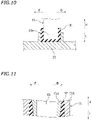
FIG. 10 is a cross-sectional view showing a damper arranged between a third case part and a first case part. -
FIG. 11 is a cross-sectional view showing a damper provided on a tilt shaft support portion of an attachment member. -
FIG. 12 is a plan view schematically showing a configuration of an upper case of an outboard motor according to an alternative embodiment. - Embodiments will now be described with reference to the drawings.
FIG. 1 shows awatercraft 10 including anoutboard motor 100 according to the present embodiment. The terms front, rear, left and right, as used in the description below, refers to these directions as viewed facing the forward direction of thewatercraft 10, while anaxis 7c of adrive shaft 7 to be described below extends vertically and theoutboard motor 100 is not inclined left and right relative to ahull 11. The designations F, B, L and R, as used in the figures, refer to front, rear, left and right, respectively. - The
watercraft 10 includes thehull 11, asteering wheel 12, aremote controller 13 and theoutboard motor 100. Theoutboard motor 100 is attached to the rear portion of thehull 11. - The
steering wheel 12 is provided for steering thehull 11. As the passenger of thewatercraft 10 operates thesteering wheel 12, theoutboard motor 100 rotates leftward or rightward relative to thehull 11. It is possible to shift gears of theoutboard motor 100. By operating theremote controller 13, the passenger can switch the state of theoutboard motor 100 between forward, backward and neutral. Theoutboard motor 100 includes anengine 1, and theengine 1 is provided with a throttle valve (not shown). By operating theremote controller 13, the passenger can adjust the opening of the throttle valve. By adjusting the opening of the throttle valve, it is possible to adjust the output power of theoutboard motor 100. -
FIG. 2 is a side view showing theoutboard motor 100. Theoutboard motor 100 includes an outboard motormain unit 101, asupport member 50 for supporting the outboard motormain unit 101, and anattachment member 70 for attaching thesupport member 50 to thehull 11. - The outboard motor
main unit 101 includes theengine 1, apropulsion unit 5 including apropeller 3, thedrive shaft 7 connected to theengine 1 and thepropulsion unit 5, and anupper case 20. Theupper case 20 is arranged between theengine 1 and thepropulsion unit 5. Theengine 1 is arranged upward of theupper case 20. Thepropulsion unit 5 is arranged downward of theupper case 20 and is arranged downward of theengine 1. - The
engine 1 is an internal combustion engine that is driven through combustion of fuel such as gasoline or diesel oil. Theengine 1 is covered by acover 2. - The
drive shaft 7 is configured to transmit power output from theengine 1 to thepropulsion unit 5. Thedrive shaft 7 extends downward from theengine 1. Thedrive shaft 7 rotates by being driven by theengine 1. - The
propulsion unit 5 includes apropeller shaft 9 on which thepropeller 3 is provided, agear device 15 that links together thedrive shaft 7 and thepropeller shaft 9, and alower case 6. Thegear device 15 transmits the rotation of thedrive shaft 7 to thepropeller shaft 9 while decelerating the rotation. Although not shown in the figure, thegear device 15 includes a pinion gear, a forward bevel gear, a backward bevel gear and a dog clutch. A gear device well known in the art can be suitably used as thegear device 15. Thepropeller 3 rotates together with thepropeller shaft 9, thereby generating forward or backward propulsion. - The
upper case 20 is composed of a plurality ofcase parts 21 to 26 to be described below. Thesecase parts 21 to 26 are formed separately from each other. That is, thecase parts 21 to 26 are separate parts. - The
upper case 20 includes anupper plate part 25 and alower plate part 26 as case parts. Here, theupper plate part 25 and thelower plate part 26 are each formed in a horizontal plate shape. Note however that there is no particular limitation on the shape of theupper plate part 25 and thelower plate part 26. Theupper plate part 25 and thelower plate part 26 extend in the left-right direction and in the front-rear direction. Theengine 1 is attached to theupper plate part 25. Theupper plate part 25 is an example of the "engine attachment portion" to which theengine 1 is attached. Apropulsion unit 6 is attached to thelower plate part 26. Thelower plate part 26 is an example of the "propulsion unit attachment portion" to which thepropulsion unit 6 is attached. - As shown in
FIG. 3 andFIG. 4 , theupper case 20 includes, as case parts, afirst case part 21 and asecond case part 22 that oppose each other in the direction perpendicular to theaxis 7c of thedrive shaft 7. Thefirst case part 21 and thesecond case part 22 each extend in the up-down direction. Thefirst case part 21 and thesecond case part 22 each extend in the front-rear direction. Thedrive shaft 7 is arranged between thefirst case part 21 and thesecond case part 22. In the present embodiment, thesecond case part 22 is arranged rightward of thefirst case part 21. Thefirst case part 21 is arranged leftward of thedrive shaft 7, and thesecond case part 22 is arranged rightward of thedrive shaft 7. -
FIG. 5 is a front surface view showing thefirst case part 21, as thefirst case part 21 is viewed from the left side.FIG. 6 is a reverse surface view showing thefirst case part 21, as thefirst case part 21 is viewed from the right side. Thefirst case part 21 includes amain body 31 having a curved plate shape extending in the up-down direction and the front-rear direction, and a plurality ofreinforcement ribs 33 provided on themain body 31. The dimension of thefirst case part 21 in the up-down direction is larger than that in the front-rear direction and larger than that in the left-right direction. - As shown in
FIG. 6 , thereinforcement ribs 33 are provided on the reverse side of themain body 31. Thereinforcement ribs 33 are each an elongate projection that is protruding from the reverse-side surface of themain body 31. Thereinforcement ribs 33 include ahorizontal rib 33h extending in the horizontal direction,slant ribs slant rib 33e extending rearward and upward, avertical rib 33v extending in the vertical direction, and acurved rib 33f that is curved. - The
horizontal rib 33h, theslant rib 33a and thecurved rib 33f are provided along the edge of themain body 31. Theslant ribs vertical rib 33v are provided on the inside of the edge of themain body 31. - As described above, the
axis 7c of thedrive shaft 7 extends in the vertical direction. Theslant ribs axis 7c of thedrive shaft 7. Theslant ribs slant ribs propeller 3 as they extend rearward. Thehorizontal rib 33h extends in a direction perpendicular to a direction parallel to theaxis 7c of thedrive shaft 7. - As shown in
FIG. 5 , themain body 31 includes through holes 32. The through holes 32 are open in a direction perpendicular to theaxis 7c of thedrive shaft 7. Here, the throughholes 32 are open leftward and rightward. In the present embodiment, themain body 31 includes three throughholes 32. Note however that there is no limitation on the number of throughholes 32. The number of throughholes 32 may be two or four or more. The number of throughholes 32 is not limited to more than one, but may be one. The through holes 32 are provided so as to reduce the weight of thefirst case part 21. In the present embodiment, the three throughholes 32 are arranged in the up-down direction. Note however that there is no particular limitation on the arrangement of the through holes 32. There is no limitation on the shapes of the through holes 32. - The
second case part 22 has a shape that is in left-right symmetry with thefirst case part 21. Therefore, elements of thesecond case part 22 corresponding to those of thefirst case part 21 are denoted by like reference signs, and the configuration of thesecond case part 22 will not be described. - As shown in
FIG. 3 , theupper case 20 includes, as case parts, athird case part 23 and afourth case part 24 connected to thefirst case part 21 and thesecond case part 22, respectively. Thethird case part 23 and thefourth case part 24 are provided bridging between thefirst case part 21 and thesecond case part 22. Thethird case part 23 and thefourth case part 24 extend in the left-right direction. Here, thethird case part 23 and thefourth case part 24 extend perpendicular to thefirst case part 21 and thesecond case part 22. Note however that there is no limitation thereto. Thethird case part 23 or thefourth case part 24 may extend slant relative to at least one of thefirst case part 21 and thesecond case part 22. Thefourth case part 24 is arranged upward of thethird case part 23. Thethird case part 23 is arranged downward relative to the middle position of thefirst case part 21 and thesecond case part 22 in the up-down direction. Thefourth case part 24 is arranged upward relative to the middle position of thefirst case part 21 and thesecond case part 22 in the up-down direction. Thethird case part 23 and thefourth case part 24 each have ahole 37 through which asteering shaft 61, 62 (seeFIG. 2 ) to be described below is inserted. - As shown in
FIG. 3 , afirst reinforcement member 27 is connected to thefirst case part 21 and thesecond case part 22. Thefirst reinforcement member 27 is provided bridging between thefirst case part 21 and thesecond case part 22. Thefirst reinforcement member 27 extends in the left-right direction. Here, thefirst reinforcement member 27 extends perpendicular to thefirst case part 21 and thesecond case part 22. Note however that there is no limitation thereto. Thefirst reinforcement member 27 may extend slant relative to at least one of thefirst case part 21 and thesecond case part 22. Thefirst reinforcement member 27 is arranged upward of thethird case part 23 and downward of thefourth case part 24. - As shown in
FIG. 4 , asecond reinforcement member 28 is connected to thefirst case part 21, thesecond case part 22 and theupper plate part 25. Thesecond reinforcement member 28 is formed in a triangular ring shape. Thesecond reinforcement member 28 is provided bridging between thefirst case part 21, thesecond case part 22 and theupper plate part 25. Thesecond reinforcement member 28 is arranged upward relative to thethird case part 23. - The
upper case 20 is obtained by assembling together thecase parts 21 to 26. In the present embodiment, thecase parts 21 to 26 include bolt holes 35. Thecase parts 21 to 26 are assembled together bybolts 36 inserted through these bolt holes 35 (seeFIG. 2 ). Note however that there is no particular limitation on the manner of assembly of thecase parts 21 to 26. Some or all of thecase parts 21 to 26 may be attached together by means of fastening devices such as thebolts 36 or may be attached together by welding, or the like, without using fastening devices. - The
case parts 21 to 26 are separate from each other and are manufactured separately. Since thecase parts 21 to 26 are separate from each other, thecase parts 21 to 26 do not need to use the same material or the same manufacturing method. That is, thecase parts 21 to 26 may use the same material or may use different materials. Thecase parts 21 to 26 may include case parts of different materials. Thecase parts 21 to 26 may use the same manufacturing method or may use different manufacturing methods. Thecase parts 21 to 26 may include case parts manufactured by casting and case parts manufactured by forging. - In the present embodiment, the
first case part 21 and thesecond case part 22 are made of die-cast aluminum, and are manufactured by casting. Thethird case part 23 and thefourth case part 24 are a heat-treated aluminum forged material, and are manufactured by forging. Note however that the above description is merely illustrative, and there is no limitation on the material and the manufacturing method of the first tofourth case parts 21 to 24. Thethird case part 23 and thefourth case part 24 may be a heat-treated gravity-cast material. The mechanical strength of thethird case part 23 and thefourth case part 24 is higher than the mechanical strength of thefirst case part 21 and thesecond case part 22. - Although not shown in
FIG. 2 to FIG. 4 , the outboard motormain unit 101 further includes components such as an exhaust pipe for discharging exhaust gas of theengine 1, an oil tank for storing oil of theengine 1 and a water pump for supplying cooling water to theengine 1. The inside of theupper case 20 can be used as a space for installation of these components. Since theupper case 20 is not a closed case, these components can be arranged so as to straddle the inside and the outside of theupper case 20. - For example, as shown in
FIG. 7 , anoil tank 87 and anexhaust pipe 88 may be arranged so as to straddle the inside and the outside of theupper case 20. In the example shown inFIG. 7 , theoil tank 87 includes aninner portion 87i and an outer portion 87o. Theexhaust pipe 88 includes aninner portion 88i and an outer portion 88o. Theinner portions upper case 20, downward relative to the upper end of theupper case 20 and upward relative to the lower end thereof. Theinner portions upper case 20, upward relative to the lower end thereof, rearward relative to the front end thereof and forward relative to the rear end thereof. Theinner portions upper case 20 as viewed in a side view. On the other hand, the outer portions 87o and 88o is located outside theupper case 20, downward relative to the upper end of theupper case 20 and upward relative to the lower end thereof. The outer portions 87o and 88o do not overlap with theupper case 20 as viewed in a side view. - As shown in
FIG. 2 , thesupport member 50 that horizontally rotatably supports the outboard motormain unit 101 includes anupper support member 51, and alower support member 52 that is spaced apart downward from theupper support member 51. Thefourth case part 24 is horizontally rotatably connected to theupper support member 51 by theupper steering shaft 61. Thethird case part 23 is horizontally rotatably connected to thelower support member 52 by thelower steering shaft 62. Theupper steering shaft 61 and thelower steering shaft 62 are arranged on thesame axis 60c (hereinafter referred to as the steering axis). Thedrive shaft 7 is inserted through theupper steering shaft 61 and thelower steering shaft 62. The steeringaxis 60c coincides with theaxis 7c of thedrive shaft 7. The outboard motormain unit 101 can rotate leftward and rightward about the steeringaxis 60c. Theupper steering shaft 61 and thelower steering shaft 62 horizontally rotatably connect theupper case 20 to thesupport member 50. In the present embodiment, theupper steering shaft 61 and thelower steering shaft 62 are separated from each other. Note however that theupper steering shaft 61 and thelower steering shaft 62 may be connected together. The steering shafts may be a single shaft. - A
reinforcement member 85 is connected to theupper support member 51 and thelower support member 52. The upper end portion of thereinforcement member 85 is secured to theupper support member 51, and the lower end portion of thereinforcement member 85 is secured to thelower support member 52. Thereinforcement member 85 extends rearward and downward, bridging between theupper support member 51 and thelower support member 52. - The
attachment member 70 is attached to a rear portion of thehull 11. Thesupport member 50 is vertically rotatably connected to theattachment member 70 by atilt shaft 65 extending in the left-right direction. Thetilt shaft 65 vertically rotatably links thesupport member 50 to theattachment member 70. Here, theattachment member 70 is vertically rotatably connected to theupper support member 51 by thetilt shaft 65. - A
tilt cylinder 80 is connected to theattachment member 70 and thesupport member 50. Thetilt cylinder 80 is vertically rotatably connected to theattachment member 70 and thesupport member 50. Specifically, thetilt cylinder 80 includes acylinder 81 and arod 82. Anupper end portion 81a of thecylinder 81 is vertically rotatably connected to theattachment member 70. Alower end portion 82a of therod 82 is vertically rotatably connected to thelower support member 52. Thesupport member 50 and the outboard motormain unit 101 rotate about thetilt shaft 65 as therod 82 extends and retracts. InFIG. 2 , thesupport member 50 and the outboard motormain unit 101 rotate counterclockwise when therod 82 extends, and rotates clockwise when therod 82 retracts. - The
outboard motor 100 according to the present embodiment is configured as described above. Next, various advantageous effects of theoutboard motor 100 according to the present embodiment will be described. - With the
outboard motor 100 according to the present embodiment, theupper case 20 is obtained by assembling together thecase parts 21 to 26. As compared with theupper case 20 where it is formed as a single part, thecase parts 21 to 26 each have a relatively simple and small configuration. Therefore, it is possible to relatively easily manufacture theupper case 20 even when theupper case 20 has a complicated or large configuration. - The
case parts 21 to 26 include thefirst case part 21 and thesecond case part 22 that oppose each other in the direction perpendicular to theaxis 7c of thedrive shaft 7. Even when the size of theupper case 20 in the up-down direction (the size in the direction of theaxis 7c of the drive shaft 7) is large, it is possible to easily manufacture thefirst case part 21 and thesecond case part 22. When thefirst case part 21 and thesecond case part 22 are assembled on top of each other, they need to have a flange, which leads to an increase in weight, but there is no need for such a flange in the present embodiment. With theoutboard motor 100 according to the present embodiment, even when theupper case 20 has a complicated or large configuration, it is possible to prevent an increase in weight while ensuring a sufficient mechanical strength. - The
drive shaft 7 is arranged between thefirst case part 21 and thesecond case part 22. Thus, thefirst case part 21 and thesecond case part 22 can serve the role of guiding thedrive shaft 7 downward from theengine 1 toward thepropulsion unit 5. - The
upper case 20 includes theupper plate part 25 to which theengine 1 is attached, and thelower plate part 26 to which thepropulsion unit 5 is attached. Thefirst case part 21 and thesecond case part 22 each extend in the up-down direction. Thus, it is possible to prevent an increase in weight while ensuring a sufficient mechanical strength of theupper case 20. - The
first case part 21 is arranged leftward of thedrive shaft 7, and thesecond case part 22 is arranged rightward of thedrive shaft 7. Thus, the configuration of theupper case 20 can be made relatively simple. - The
upper case 20 includes thethird case part 23 that is provided bridging between thefirst case part 21 and thesecond case part 22. Thus, the configuration of theupper case 20 can be made relatively simple while ensuring a sufficient mechanical strength. - According to the present embodiment, the
third case part 23 extends perpendicular to thefirst case part 21 and thesecond case part 22. Thus, it is possible to ensure a sufficient mechanical strength of theupper case 20. - The
case parts 21 to 26 of theupper case 20 are separate from each other. Thecase parts 21 to 26 are separately manufactured. Therefore, there is no such limitation that thecase parts 21 to 26 need to use the same material. In the present embodiment, thecase parts 21 to 26 of theupper case 20 include case parts of different materials. With theoutboard motor 100 according to the present embodiment, there is fewer limitations on the material of theupper case 20. By appropriately selecting the material of each of thecase parts 21 to 26, it is possible to prevent an increase in weight while ensuring a sufficient mechanical strength of theupper case 20. - According to the present embodiment, there is no such limitation that the
case parts 21 to 26 need to use the same manufacturing method. In the present embodiment, thecase parts 21 to 26 of theupper case 20 include thecase parts case parts case parts 21 to 26, it is possible to relatively easily manufacture theupper case 20 and to prevent an increase in weight while ensuring a sufficient mechanical strength even when theupper case 20 has a complicated or large configuration. - The
first case part 21 and thesecond case part 22 include thereinforcement ribs 33 in addition to the main body 31 (seeFIG. 6 ). Thereinforcement ribs 33 include thehorizontal rib 33h extending in a direction perpendicular to a direction parallel to theaxis 7c of thedrive shaft 7, and theslant ribs 33a to 33e extending slant relative to a direction parallel to theaxis 7c of thedrive shaft 7. When the upper case is produced as a single tubular part that is manufactured by casting as with conventional techniques, it is difficult to form the horizontal rib and the slant ribs. However, according to the present embodiment, it is easy to provide thehorizontal rib 33h and theslant ribs 33a to 33e on thefirst case part 21 and thesecond case part 22. Therefore, it is possible to increase the mechanical strength of thefirst case part 21 and thesecond case part 22 without increasing the thickness of themain body 31. Thus, it is possible to prevent an increase in weight while ensuring a sufficient mechanical strength of theupper case 20. - As shown in
FIG. 2 , thepropulsion unit 5 is connected to a lower portion of theupper case 20. While thepropeller 3 of thepropulsion unit 5 rotates to generate forward propulsion, the rear portion of theupper case 20 is pulled rearward and downward. Reference sign F1 inFIG. 2 denotes the pulling force generated at the rear portion of theupper case 20. In the present embodiment, thefirst case part 21 and thesecond case part 22 include theslant ribs 33a to 33c extending rearward and downward (seeFIG. 6 ). Therefore, it is possible to ensure a sufficient mechanical strength of theupper case 20 for the pulling force F1. - As shown in
FIG. 5 , the throughholes 32 are formed in thefirst case part 21 and thesecond case part 22. Note that as opposed to the bolt holes 35 in which thebolts 36 are inserted, the throughholes 32 are holes that are open when theupper case 20 is assembled (seeFIG. 2 ). The through holes 32 are holes that are always open without being closed by thebolts 36, etc. With the throughholes 32 formed in thefirst case part 21 and thesecond case part 22, it is possible to reduce the weight of thefirst case part 21 and thesecond case part 22. Thus, it is possible to reduce the weight of theupper case 20. - As shown in
FIG. 7 , in the present embodiment, theoil tank 87 includes theinner portion 87i that is located inside theupper case 20 and the outer portion 87o that is located outside theupper case 20. Theexhaust pipe 88 includes theinner portion 88i that is located inside theupper case 20 and the outer portion 88o that is located outside theupper case 20. Since theupper case 20 is not a case having a closed tubular shape, theoil tank 87 and theexhaust pipe 88 can be arranged so as to straddle the inside and the outside of theupper case 20. According to the present embodiment, there is a high degree of freedom in the arrangement of parts such as theoil tank 87 and theexhaust pipe 88. - The
upper case 20 includes thefourth case part 24 through which theupper steering shaft 61 is inserted and thethird case part 23 through which thelower steering shaft 62 is inserted. Theupper steering shaft 61 and thelower steering shaft 62 are arranged inside theupper case 20. Therefore, as compared with a case where the steering shafts are arranged forward relative to theupper case 20, it is possible to reduce the size of theoutboard motor 100. - The
upper case 20 includes thefirst reinforcement member 27 secured to thefirst case part 21 and thesecond case part 22. Theupper case 20 also includes thesecond reinforcement member 28 secured to thefirst case part 21, thesecond case part 22 and theupper plate part 25. With thefirst reinforcement member 27 and thesecond reinforcement member 28, it is possible to further increase the mechanical strength of theupper case 20. - The
outboard motor 100 according to the second embodiment is similar to theoutboard motor 100 according to the first embodiment, with a change made to the configuration of theupper case 20. In the following description, like elements to those of the first embodiment will be denoted by like reference signs, and will not be further described below. -
FIG. 8 is a perspective view showing theupper case 20 of theoutboard motor 100 according to the second embodiment. As in the first embodiment, theupper case 20 is obtained by assembling together thefirst case part 21, thesecond case part 22, thethird case part 23, thefourth case part 24, theupper plate part 25 and thelower plate part 26. Although not shown in the figure, theengine 1 is attached to theupper plate part 25, and thepropulsion unit 5 is attached to thelower plate part 26. - The configuration of the
first case part 21 and thesecond case part 22 according to the second embodiment is different from the configuration of thefirst case part 21 and thesecond case part 22 according to the first embodiment. In the second embodiment, reinforcement ribs are not provided on thefirst case part 21 and thesecond case part 22. Note however that also in the second embodiment, thefirst case part 21 and thesecond case part 22 includes the throughholes 32 that are open leftward and rightward. Thefirst case part 21 is arranged leftward of the steering shaft (not shown), and thesecond case part 22 is arranged rightward of the steering shaft. - The
first reinforcement member 27 is connected to thefirst case part 21 and thesecond case part 22. Thefirst reinforcement member 27 extends in the left-right direction, bridging between thefirst case part 21 and thesecond case part 22. In the present embodiment, thefirst reinforcement member 27 is arranged downward of thethird case part 23. Thesecond reinforcement member 28 is connected to thefirst case part 21, thesecond case part 22 and theupper plate part 25. - As shown in
FIG. 9 , the upper steering shaft 61 (seeFIG. 8 ) is inserted through thefourth case part 24, theupper support member 51 is attached to theupper steering shaft 61. The lower steering shaft 62 (seeFIG. 8 ) is inserted through thethird case part 23, and thelower support member 52 is attached to thelower steering shaft 62. Theupper case 20 is horizontally rotatably supported on theupper support member 51 and thelower support member 52. Although not shown in the figure, also in the present embodiment, thedrive shaft 7 is inserted through theupper steering shaft 61 and the lower steering shaft 62 (seeFIG. 2 ). The axes of theupper steering shaft 61, thelower steering shaft 62 and thedrive shaft 7 coincide with each other. - The
upper support member 51 is vertically rotatably supported on theattachment member 70 by thetilt shaft 65 extending in the left-right direction. Thelower support member 52 is vertically rotatably supported on theattachment member 70 via thetilt cylinder 80. - In the present embodiment, a
rubber damper 91 is arranged between thethird case part 23 and thefirst case part 21 and between thethird case part 23 and thesecond case part 22. As shown inFIG. 10 , thethird case part 23 and thefirst case part 21 are assembled together with thedamper 91 therebetween. Aleft end portion 23a of thethird case part 23 and thefirst case part 21 are not in direct contact with each other but are in indirect contact with each other with thedamper 91 therebetween. Although not shown in the figure, the right end portion of thethird case part 23 and thesecond case part 22 are not in direct contact with each other but are in indirect contact with each other with thedamper 91 therebetween. - As shown in
FIG. 9 , theattachment member 70 includes the tiltshaft support portion 71 that supports thetilt shaft 65. Adamper 92 is provided on the tiltshaft support portion 71. As shown inFIG. 11 , the tiltshaft support portion 71 includes aninner member 71a and anouter member 71b each having a cylindrical shape. Theinner member 71a is arranged on the inner side of theouter member 71b. Thetilt shaft 65 is rotatably supported on theinner member 71a. Thedamper 92 is made of rubber, and is arranged between theinner member 71a and theouter member 71b. The shape of thedamper 92 is tubular and tapered. - As shown in
FIG. 9 , theattachment member 70 includes a connectingportion 73 to which thetilt cylinder 80 is connected. Theupper end portion 81a of thecylinder 81 of thetilt cylinder 80 is connected to the connectingportion 73. Arubber damper 93 is provided on the connectingportion 73. Thelower support member 52 includes a connectingportion 56 to which thetilt cylinder 80 is connected. Thelower end portion 82a of therod 82 of thetilt cylinder 80 is connected to the connectingportion 56. Arubber damper 94 is provided on the connectingportion 56. - Also in the second embodiment, similar advantageous effects to those of the first embodiment can be realized. In addition, according to the present embodiment, it is possible, with the
dampers 91 to 94, to reduce vibrations transmitted to thehull 11 from theengine 1 and thepropulsion unit 5. - While the first embodiment and the second embodiment have been described above, the first embodiment and the second embodiment are merely illustrative, and various alternative embodiments are possible. Alternative embodiments will now be described briefly.
- The
first case part 21 and thesecond case part 22 do not always need to be arranged leftward and rightward, respectively, of thedrive shaft 7. Thefirst case part 21 and thesecond case part 22 do not always need to be opposing each other in the left-right direction. For example, as schematically shown inFIG. 12 , thefirst case part 21 and thesecond case part 22 may be arranged so as to oppose each other in the front-rear direction. In the example shown inFIG. 12 , theupper case 20 includes aleft case part 29L and aright case part 29R extending in the front-rear direction, in addition to the first tofourth case parts 21 to 24. Theleft case part 29L and theright case part 29R are connected to thefirst case part 21 and thesecond case part 22, bridging between thefirst case part 21 and thesecond case part 22. - In the embodiments described above, the
upper case 20 includes theupper plate part 25 and thelower plate part 26. However, while theupper plate part 25 serves the role of stably supporting theengine 1, theupper plate part 25 is not always needed. Theupper plate part 25 may be absent as long as theengine 1 can be stably supported. While thelower plate part 26 serves the role of stably supporting thepropulsion unit 5, thelower plate part 26 is not always needed. Thelower plate part 26 may be absent as long as thepropulsion unit 5 can be stably supported. - While the
upper case 20 includes thethird case part 23 and thefourth case part 24 bridging between thefirst case part 21 and thesecond case part 22 in the embodiments described above, thethird case part 23 and thefourth case part 24 are not always needed. Thefirst case part 21 and thesecond case part 22 may be indirectly connected together or may be directly connected together. - The
upper case 20 may or may not include thereinforcement ribs 33. Thefirst case part 21 and thesecond case part 22 may include thereinforcement ribs 33 as in the first embodiment or may not include thereinforcement ribs 33.Other case parts 23 to 26 may include thereinforcement ribs 33. - The
first case part 21 and thesecond case part 22 may not include the through holes 32.Other case parts 23 to 26 may include the through holes 32. - The steering shaft may not be inserted through the
upper case 20. The case parts of theupper case 20 may not include a case part through which the steering shaft is inserted. The steering shaft may be arranged forward of theupper case 20. - As in the second embodiment, some or all of the
dampers 91 to 94 may be provided in theoutboard motor 100 according to the first embodiment. In theoutboard motor 100 according to the second embodiment, some or all of thedampers 91 to 94 may be absent. In theoutboard motor 100, thedampers 91 to 94 may or may not be provided. - While the
first reinforcement member 27 and thesecond reinforcement member 28 are effective for increasing the mechanical strength of theupper case 20, one or both of thefirst reinforcement member 27 and thesecond reinforcement member 28 may be absent as long as a sufficient mechanical strength is ensured for theupper case 20. Theupper case 20 may include other reinforcement members that connect together two or more case parts. - 1: Engine, 5: Propulsion unit, 7: Drive shaft, 11: Hull, 20: Uppercase (case), 21: First case part, 22: Second case part, 23: Third case part, 24: Fourth case part, 25: Upper plate part (engine attachment portion), 26: Lower plate part (propulsion unit attachment portion), 27: First reinforcement member, 28: Second reinforcement member, 32: Through hole, 33: Reinforcement ribs, 50: Support member, 56: Connecting portion, 61: Upper steering shaft, 62: Lower steering shaft, 65: Tilt shaft, 70: Attachment member, 71: Tilt shaft support portion, 73: Connecting portion, 80: Tilt cylinder, 87: Oil tank, 87i: Inner portion, 87o: Outer portion, 88: Exhaust pipe, 88i: Inner portion, 88o: Outer portion, 91 to 94: Damper, 100: Outboard motor
Claims (15)
- An outboard motor (100) configured to be attachable to a watercraft (10) and especially with regard to the outboard motor (100) attached the watercraft (10), the outboard motor (100) comprising:an engine (1);a propulsion unit (5) arranged downward of the engine (1) and including a propeller (3);a drive shaft (7) connected to the engine (1) and the propulsion unit (5) so as to transmit a drive force from the engine (1) to the propulsion unit (5); anda case (20) arranged between the engine (1) and the propulsion unit (5) and including an engine attachment portion (25) to which the engine (1) is attached and a propulsion unit attachment portion (26) to which the propulsion unit (5) is attached,wherein:the case (20) is composed of a plurality of case parts (21 to 26) that are formed separately from each other and assembled together; andthe case parts (21 to 26) include a first case part (21) and a second case part (22) opposing each other in a direction perpendicular to an axis (7c) of the drive shaft (7).
- The outboard motor (100) according to claim 1, wherein the drive shaft (7) is arranged between the first case part (21) and the second case part (22).
- The outboard motor (100) according to claim 1 or 2, wherein the case parts (21 to 26) include an upper plate part (25) to which the engine (1) is attached and a lower plate part (26) to which the propulsion unit (5) is attached;the engine attachment portion of the case (20) is the upper plate part (25);the propulsion unit attachment portion of the case (20) is the lower plate part (26); andthe first case part (21) and the second case part (22) each extend in an up-down direction.
- The outboard motor (100) according to any one of claims 1 to 3, wherein the first case part (21) is arranged leftward of the drive shaft (7), and the second case part (22) is arranged rightward of the drive shaft (7).
- The outboard motor (100) according to any one of claims 1 to 4, wherein the case parts (21 to 26) include a third case part (23) connected to the first case part (21) and the second case part (22), bridging between the first case part (21) and the second case part (22).
- The outboard motor (100) according to claim 5, wherein the third case part (23) extends perpendicular to the first case part (21) and the second case part (22).
- The outboard motor (100) according to any one of claims 1 to 6, wherein the case parts (21 to 26) include case parts of different materials; and/or
the case parts (21 to 26) include a case part (21, 22) manufactured by casting and a case part (23, 24) manufactured by forging. - The outboard motor (100) according to any one of claims 1 to 7, wherein the first case part (21) and/or the second case part (22) include a reinforcement rib (33) extending in a direction perpendicular to or slant relative to a direction parallel to an axis (7c) of the drive shaft (7); and/or
the first case part (21) and/or the second case part (22) include a reinforcement rib (33a, 33b, 33c) extending rearward and downward. - The outboard motor (100) according to any one of claims 1 to 8, wherein a through hole (32) that is open in a direction perpendicular to an axis (7c) of the drive shaft (7) is formed in the first case part (21) and/or the second case part (22).
- The outboard motor (100) according to any one of claims 1 to 9, comprising a part (87, 88) including an inner portion (87i, 88i) that is located inside the case (20), downward relative to an upper end of the case (20) and upward relative to a lower end of the case (20), and an outer portion (87o, 88o) that is located outside the case (20), downward relative to the upper end of the case (20) and upward relative to the lower end of the case (20).
- The outboard motor (100) according to any one of claims 1 to 10, comprising:an attachment member (70) attached to a hull (11) of the watercraft (10);a support member (50) attached to the attachment member (70) and the case (20);a tilt shaft (65) that vertically rotatably links the support member (50) to the attachment member (70); anda steering shaft (61, 62) that horizontally rotatably links the case (20) to the support member (50).
- The outboard motor (100) according to claim 11, wherein the case parts (21 to 26) include a case part (23, 24) in which the steering shaft (61, 62) is inserted; and/or
the outboard motor (100) comprises a damper (91) arranged between any two of the case parts (21 to 26). - The outboard motor (100) according to claims 11 or 12, wherein:the attachment member (70) includes a tilt shaft support portion (71) supporting the tilt shaft (65); anda damper (92) is provided on the tilt shaft support portion (71).
- The outboard motor (100) according to any one of claims 11 to 13, comprising:
a tilt cylinder (80) connected to the attachment member (70) and the support member (50), wherein:the attachment member (70) and/or the support member (50) includes a connecting portion (73, 56) connected to the tilt cylinder (80); anda damper (93, 94) is provided on the connecting portion (73, 56). - The outboard motor (100) according to any one of claims 1 to 14, comprising a reinforcement member (27, 28) secured to at least two of the case parts (21 to 26).
Applications Claiming Priority (1)
| Application Number | Priority Date | Filing Date | Title |
|---|---|---|---|
| JP2020212111A JP2022098622A (en) | 2020-12-22 | 2020-12-22 | Outboard engine |
Publications (1)
| Publication Number | Publication Date |
|---|---|
| EP4019393A1 true EP4019393A1 (en) | 2022-06-29 |
Family
ID=78087049
Family Applications (1)
| Application Number | Title | Priority Date | Filing Date |
|---|---|---|---|
| EP21201678.6A Pending EP4019393A1 (en) | 2020-12-22 | 2021-10-08 | Outboard motor |
Country Status (3)
| Country | Link |
|---|---|
| US (1) | US12195155B2 (en) |
| EP (1) | EP4019393A1 (en) |
| JP (1) | JP2022098622A (en) |
Families Citing this family (1)
| Publication number | Priority date | Publication date | Assignee | Title |
|---|---|---|---|---|
| JP7350038B2 (en) | 2021-11-11 | 2023-09-25 | ヤマハ発動機株式会社 | Outboard motor suspension structure, outboard motor |
Citations (4)
| Publication number | Priority date | Publication date | Assignee | Title |
|---|---|---|---|---|
| US5487687A (en) * | 1994-07-18 | 1996-01-30 | Brunswick Corporation | Midsection and cowl assembly for an outboard marine drive |
| US20050250394A1 (en) * | 2004-05-07 | 2005-11-10 | Daisuke Nakamura | Outboard motor with bracket assembly |
| JP2009160970A (en) | 2007-12-28 | 2009-07-23 | Yamaha Motor Co Ltd | Outboard motor |
| US9376191B1 (en) * | 2014-06-27 | 2016-06-28 | Brunswick Corporation | Outboard motor with lightweight midsection housing |
Family Cites Families (2)
| Publication number | Priority date | Publication date | Assignee | Title |
|---|---|---|---|---|
| US4080099A (en) * | 1976-05-02 | 1978-03-21 | Brunswick Corporation | Propeller |
| CA2584386C (en) * | 2006-05-01 | 2013-11-19 | Honda Motor Co., Ltd. | Outboard engine unit |
-
2020
- 2020-12-22 JP JP2020212111A patent/JP2022098622A/en active Pending
-
2021
- 2021-10-08 EP EP21201678.6A patent/EP4019393A1/en active Pending
- 2021-11-08 US US17/520,777 patent/US12195155B2/en active Active
Patent Citations (4)
| Publication number | Priority date | Publication date | Assignee | Title |
|---|---|---|---|---|
| US5487687A (en) * | 1994-07-18 | 1996-01-30 | Brunswick Corporation | Midsection and cowl assembly for an outboard marine drive |
| US20050250394A1 (en) * | 2004-05-07 | 2005-11-10 | Daisuke Nakamura | Outboard motor with bracket assembly |
| JP2009160970A (en) | 2007-12-28 | 2009-07-23 | Yamaha Motor Co Ltd | Outboard motor |
| US9376191B1 (en) * | 2014-06-27 | 2016-06-28 | Brunswick Corporation | Outboard motor with lightweight midsection housing |
Also Published As
| Publication number | Publication date |
|---|---|
| US12195155B2 (en) | 2025-01-14 |
| US20220194540A1 (en) | 2022-06-23 |
| JP2022098622A (en) | 2022-07-04 |
Similar Documents
| Publication | Publication Date | Title |
|---|---|---|
| US20230174212A1 (en) | Drive arrangement for a marine vessel | |
| JP2007055310A (en) | Outboard motor | |
| JP6946997B2 (en) | Oil pan guard for vehicles | |
| US12195155B2 (en) | Outboard motor | |
| EP3403916A1 (en) | Outboard motor | |
| US12358602B2 (en) | Hybrid ship propulsion machine | |
| US12434787B2 (en) | Hybrid power unit, hybrid straddle vehicle, and case of hybrid power unit | |
| EP4019392B1 (en) | Outboard motor | |
| JP5859353B2 (en) | Suspension device | |
| JP7147349B2 (en) | Outboard motor | |
| US7845997B2 (en) | Boat-propelling machine | |
| JP5844668B2 (en) | Suspension device | |
| US12384502B2 (en) | Outboard motor and boat | |
| US7238070B2 (en) | Outboard motor | |
| US12617454B2 (en) | Agricultural tractor | |
| US20240208628A1 (en) | Outboard motor | |
| JP4055906B2 (en) | Drive axle mounting structure for work vehicle | |
| JP2024152242A (en) | Outboard motors and marine vehicles | |
| JP2018086952A (en) | Outboard motor shift device | |
| JP7105554B2 (en) | Outboard motor | |
| JP2005082128A (en) | HST mounting structure of work vehicle | |
| JP2024152243A (en) | Outboard motors and marine vehicles | |
| JP4719439B2 (en) | Drive device | |
| JP4128921B2 (en) | Tractor | |
| JP5623659B2 (en) | Straddle-type electric vehicle |
Legal Events
| Date | Code | Title | Description |
|---|---|---|---|
| PUAI | Public reference made under article 153(3) epc to a published international application that has entered the european phase |
Free format text: ORIGINAL CODE: 0009012 |
|
| STAA | Information on the status of an ep patent application or granted ep patent |
Free format text: STATUS: THE APPLICATION HAS BEEN PUBLISHED |
|
| AK | Designated contracting states |
Kind code of ref document: A1 Designated state(s): AL AT BE BG CH CY CZ DE DK EE ES FI FR GB GR HR HU IE IS IT LI LT LU LV MC MK MT NL NO PL PT RO RS SE SI SK SM TR |
|
| STAA | Information on the status of an ep patent application or granted ep patent |
Free format text: STATUS: REQUEST FOR EXAMINATION WAS MADE |
|
| 17P | Request for examination filed |
Effective date: 20221209 |
|
| RBV | Designated contracting states (corrected) |
Designated state(s): AL AT BE BG CH CY CZ DE DK EE ES FI FR GB GR HR HU IE IS IT LI LT LU LV MC MK MT NL NO PL PT RO RS SE SI SK SM TR |
|
| STAA | Information on the status of an ep patent application or granted ep patent |
Free format text: STATUS: EXAMINATION IS IN PROGRESS |
|
| 17Q | First examination report despatched |
Effective date: 20240703 |