EP4019392A1 - Outboard motor - Google Patents
Outboard motor Download PDFInfo
- Publication number
- EP4019392A1 EP4019392A1 EP21200945.0A EP21200945A EP4019392A1 EP 4019392 A1 EP4019392 A1 EP 4019392A1 EP 21200945 A EP21200945 A EP 21200945A EP 4019392 A1 EP4019392 A1 EP 4019392A1
- Authority
- EP
- European Patent Office
- Prior art keywords
- reinforcement member
- support member
- outboard motor
- connecting portion
- relative
- Prior art date
- Legal status (The legal status is an assumption and is not a legal conclusion. Google has not performed a legal analysis and makes no representation as to the accuracy of the status listed.)
- Granted
Links
Images




Classifications
-
- B—PERFORMING OPERATIONS; TRANSPORTING
- B63—SHIPS OR OTHER WATERBORNE VESSELS; RELATED EQUIPMENT
- B63H—MARINE PROPULSION OR STEERING
- B63H20/00—Outboard propulsion units, e.g. outboard motors or Z-drives; Arrangements thereof on vessels
- B63H20/02—Mounting of propulsion units
-
- B—PERFORMING OPERATIONS; TRANSPORTING
- B63—SHIPS OR OTHER WATERBORNE VESSELS; RELATED EQUIPMENT
- B63H—MARINE PROPULSION OR STEERING
- B63H20/00—Outboard propulsion units, e.g. outboard motors or Z-drives; Arrangements thereof on vessels
- B63H20/08—Means enabling movement of the position of the propulsion element, e.g. for trim, tilt or steering; Control of trim or tilt
-
- B—PERFORMING OPERATIONS; TRANSPORTING
- B63—SHIPS OR OTHER WATERBORNE VESSELS; RELATED EQUIPMENT
- B63H—MARINE PROPULSION OR STEERING
- B63H20/00—Outboard propulsion units, e.g. outboard motors or Z-drives; Arrangements thereof on vessels
- B63H20/08—Means enabling movement of the position of the propulsion element, e.g. for trim, tilt or steering; Control of trim or tilt
- B63H20/10—Means enabling trim or tilt, or lifting of the propulsion element when an obstruction is hit; Control of trim or tilt
-
- B—PERFORMING OPERATIONS; TRANSPORTING
- B63—SHIPS OR OTHER WATERBORNE VESSELS; RELATED EQUIPMENT
- B63H—MARINE PROPULSION OR STEERING
- B63H20/00—Outboard propulsion units, e.g. outboard motors or Z-drives; Arrangements thereof on vessels
- B63H20/08—Means enabling movement of the position of the propulsion element, e.g. for trim, tilt or steering; Control of trim or tilt
- B63H20/12—Means enabling steering
-
- B—PERFORMING OPERATIONS; TRANSPORTING
- B63—SHIPS OR OTHER WATERBORNE VESSELS; RELATED EQUIPMENT
- B63H—MARINE PROPULSION OR STEERING
- B63H23/00—Transmitting power from propulsion power plant to propulsive elements
- B63H23/32—Other parts
- B63H23/34—Propeller shafts; Paddle-wheel shafts; Attachment of propellers on shafts
-
- B—PERFORMING OPERATIONS; TRANSPORTING
- B63—SHIPS OR OTHER WATERBORNE VESSELS; RELATED EQUIPMENT
- B63H—MARINE PROPULSION OR STEERING
- B63H25/00—Steering; Slowing-down otherwise than by use of propulsive elements; Dynamic anchoring, i.e. positioning vessels by means of main or auxiliary propulsive elements
- B63H25/42—Steering or dynamic anchoring by propulsive elements; Steering or dynamic anchoring by propellers used therefor only; Steering or dynamic anchoring by rudders carrying propellers
Definitions
- the present invention relates to an outboard motor.
- outboard motors There are conventional outboard motors known in the art that include an outboard motor main unit having an engine and a propulsion unit, an attachment member attached to a hull, and a support member steerably supporting the outboard motor main unit on the attachment member.
- JP A 2018-2004 discloses such an outboard motor.
- the engine and the propulsion unit of the outboard motor main unit are linked together by a drive shaft extending in the up-down direction.
- the support member of the outboard motor disclosed in JP A 2018-2004 includes an upper support portion and a lower support portion that support the outboard motor main unit so as to surround the drive shaft, and a left and a right link portion that link together the upper support portion and the lower support portion.
- the lower support portion is arranged spaced apart downward from the upper support portion.
- the left and right link portions are formed in a rod shape extending parallel to the drive shaft.
- a lateral load may be applied to a lower portion of the outboard motor main unit.
- leftward or rightward water pressure may be applied to the propulsion unit.
- a lateral load is applied to the support member via the outboard motor main unit.
- An object of the present invention is to provide an outboard motor having an increased mechanical strength against lateral loads while preventing an increase in size and weight of the support member. According to the present invention said object is solved by an outboard motor having the features of independent claim 1. Preferred embodiments are laid down in the dependent claims. The subject matter of the independent claim refers to the outboard motor in specific attitude when attached the watercraft.
- An outboard motor disclosed herein includes an outboard motor main unit including an engine, a propulsion unit arranged downward of the engine, and a drive shaft connected to the engine and the propulsion unit.
- the outboard motor includes an attachment member attached to a hull; and a support member vertically rotatably connected to the attachment member and horizontally rotatably supporting the outboard motor main unit.
- the attachment member includes a left clamp bracket, and a right clamp bracket arranged rightward relative to the left clamp bracket.
- the support member includes a left side portion located rightward of the left clamp bracket and a right side portion located leftward of the right clamp bracket, and is sandwiched between the left clamp bracket and the right clamp bracket.
- the outboard motor includes: a left tilt shaft that vertically rotatably links together the left side portion of the support member and the left clamp bracket; a right tilt shaft that vertically rotatably links together the right side portion of the support member and the right clamp bracket.
- the outboard motor includes a left reinforcement member that includes a left upper connecting portion connected to the support member and located leftward relative to the left side portion of the support member, and a left lower connecting portion connected to the support member and located downward relative to the left upper connecting portion.
- the outboard motor includes a right reinforcement member that includes a right upper connecting portion connected to the support member and located rightward relative to the right side portion of the support member, and a right lower connecting portion connected to the support member and located downward relative to the right upper connecting portion.
- the outboard motor described above includes the left reinforcement member and the right reinforcement member that reinforce the support member.
- the left upper connecting portion of the left reinforcement member is connected to the support member at a position leftward relative to the left side portion of the support member, and the left lower connecting portion thereof is connected to the support member at a position downward relative to the left upper connecting portion.
- the right upper connecting portion of the right reinforcement member is connected to the support member at a position rightward relative to the right side portion of the support member, and the right lower connecting portion thereof is connected to the support member at a position downward relative to the right upper connecting portion.
- the left reinforcement member and the right reinforcement member it is possible to efficiently increase the mechanical strength of the support member against lateral loads. While a portion of the lateral load applied to the propulsion unit is transmitted to portions of the outboard motor main unit other than the propulsion unit, another portion of the lateral load is transmitted from the support member to the hull via the left reinforcement member, the right reinforcement member and the attachment member. The lateral load applied to the outboard motor main unit is reduced. Therefore, with the outboard motor described above, it is possible to increase the mechanical strength against lateral loads while preventing an increase in size and weight of the support member.
- an outboard motor having an increased mechanical strength against lateral loads while preventing an increase in size and weight of the support member.
- FIG. 1 shows a watercraft 10 including an outboard motor 100 according to the present embodiment.
- the watercraft 10 includes the hull 11, a steering wheel 12, a remote controller 13 and the outboard motor 100.
- the outboard motor 100 is attached to the rear portion of the hull 11.
- the steering wheel 12 is provided for steering the hull 11.
- the outboard motor 100 rotates leftward or rightward relative to the hull 11. It is possible to shift gears of the outboard motor 100.
- the remote controller 13 By operating the remote controller 13, the passenger can switch the state of the outboard motor 100 between forward, backward and neutral.
- the outboard motor 100 includes an engine 1, and the engine 1 is provided with a throttle valve (not shown). By operating the remote controller 13, the passenger can adjust the opening of the throttle valve. By adjusting the opening of the throttle valve, it is possible to adjust the output power of the outboard motor 100.
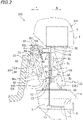
- FIG. 2 is a side view showing the outboard motor 100.
- the outboard motor 100 includes an outboard motor main unit 101, a support member 50 for supporting the outboard motor main unit 101, and an attachment member 70 for attaching the support member 50 to the hull 11.
- the outboard motor main unit 101 includes the engine 1, a propulsion unit 5 including a propeller 3, the drive shaft 7 connected to the engine 1 and the propulsion unit 5, and an upper case 20.
- the engine 1 is arranged upward of the upper case 20.
- the propulsion unit 5 is arranged downward of the upper case 20 and is arranged downward of the engine 1.
- the engine 1 is an internal combustion engine that is driven through combustion of fuel such as gasoline or diesel oil.
- the engine 1 is covered by a cover 2.
- the drive shaft 7 is configured to transmit power output from the engine 1 to the propulsion unit 5.
- the drive shaft 7 extends downward from the engine 1.
- the drive shaft 7 rotates by being driven by the engine 1.
- the propulsion unit 5 includes a propeller shaft 9 on which the propeller 3 is provided, a gear device 15 that links together the drive shaft 7 and the propeller shaft 9, and a lower case 6.
- the gear device 15 transmits the rotation of the drive shaft 7 to the propeller shaft 9 while decelerating the rotation.
- the gear device 15 includes a pinion gear, a forward bevel gear, a backward bevel gear and a dog clutch.
- a gear device well known in the art can be suitably used as the gear device 15.
- the propeller 3 rotates together with the propeller shaft 9, thereby generating forward or backward propulsion.
- FIG. 3 is a perspective view showing the upper case 20, the support member 50 and the attachment member 70.
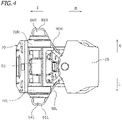
- FIG. 4 is a plan view showing the upper case 20, the support member 50 and the attachment member 70.
- FIG. 5 is a back view showing the upper case 20, the support member 50 and the attachment member 70.
- the upper case 20 is arranged between the engine 1 and the propulsion unit 5.
- the upper case 20 supports the engine 1 and also supports the propulsion unit 5.
- the upper case 20 is composed of a plurality of case parts 21 to 30.
- the case parts 21 to 30 are formed separately from each other. That is, the case parts 21 to 30 are separate parts.
- the case part 25 and the case part 26 are formed in a flat plate shape.
- the case part 26 is arranged downward of the case part 25.
- the engine 1 is attached to the case part 25.
- the propulsion unit 6 is attached to the case part 26.
- the case part 21 and the case part 22 oppose each other in a direction perpendicular to the axis 7c of the drive shaft 7 (see FIG. 2 ).
- the drive shaft 7 is arranged between the case part 21 and the case part 22.
- the case part 22 is arranged rightward of the case part 21.
- the case part 21 is arranged leftward of the drive shaft 7, and the case part 22 is arranged rightward of the drive shaft 7.
- Through holes 32 are formed in the case part 21 and the case part 22.
- the through holes 32 are open in a direction perpendicular to the axis 7c of the drive shaft 7.
- the through holes 32 are open leftward and rightward.
- the case part 29 is secured to the lower portion of the case part 21.
- the case part 30 is secured to the lower portion of the case part 22.
- the case part 29 and the case part 30 are arranged upward of the case part 26 and secured to the case part 26.
- the case part 23 is connected to the case part 21 and the case part 22.
- the case part 23 extends in the left-right direction, bridging between the lower portion of the case part 21 and the lower portion of the case part 22.
- the case part 24 is arranged upward of the case part 23.
- the case part 24 extends in the left-right direction, bridging between the upper portion of the case part 21 and the upper portion of the case part 22.
- the case part 24 is connected to the case part 21, the case part 22 and the case part 25.
- a cylindrical upper steering shaft 61 is inserted through the case part 24.
- a cylindrical lower steering shaft 62 is inserted through the case part 23.
- the drive shaft 7 is inserted through the upper steering shaft 61 and the lower steering shaft 62.
- the drive shaft 7 is arranged coaxial with the upper steering shaft 61 and the lower steering shaft 62.
- the case part 28 is connected to the case part 21, the case part 22 and the case part 25.
- the case part 27 is connected to the case part 21, the case part 29, the case part 22, the case part 30 and the case part 26.
- the upper case 20 is obtained by assembling together the case parts 21 to 30.
- the manner of assembly of the case parts 21 to 30 There is no particular limitation on the manner of assembly of the case parts 21 to 30.
- Some or all of the case parts 21 to 30 may be attached together by means of fastening devices such as bolts or may be attached together by welding, or the like, without using fastening devices.
- the support member 50 is a member that horizontally rotatably supports the outboard motor main unit 101.
- the support member 50 includes an upper support member 51 and a lower support member 52.
- the upper support member 51 supports the upper portion of the upper case 20.
- the lower support member 52 supports the lower portion of the upper case 20.
- the upper support member 51 and the lower support member 52 are separate from each other, and the lower support member 52 is spaced apart downward from the upper support member 51.
- the case part 24 is horizontally rotatably supported on the upper support member 51 by the upper steering shaft 61.
- the case part 23 is horizontally rotatably supported on the lower support member 52 by the lower steering shaft 62.
- the upper steering shaft 61 and the lower steering shaft 62 horizontally rotatably connect the upper case 20 to the support member 50.
- the axes of the upper steering shaft 61 and the lower steering shaft 62 coincide with the axis 7c of the drive shaft 7.
- the outboard motor main unit 101 can rotate leftward and rightward about the
- the attachment member 70 is attached to the rear portion of the hull 11.
- the support member 50 is connected, by a tilt shaft 65 extending in the left-right direction, to the attachment member 70.
- the tilt shaft 65 vertically rotatably links the support member 50 to the attachment member 70.
- the attachment member 70 is vertically rotatably connected to the upper support member 51 by the tilt shaft 65.
- the attachment member 70 includes a left clamp bracket 70L, and a right clamp bracket 70R arranged rightward relative to the left clamp bracket 70L. At least a portion of the upper support member 51 is sandwiched between the left clamp bracket 70L and the right clamp bracket 70R.
- the tilt shaft 65 includes a left tilt shaft 65L and a right tilt shaft 65R (see FIG. 6 ).
- the upper support member 51 includes a left cover 54L that covers the left tilt shaft 65L and a right cover 54R that covers the right tilt shaft 65R.
- the left cover 54L is arranged leftward of the left clamp bracket 70L
- the right cover 54R is arranged rightward of the right clamp bracket 70R.
- a left reinforcement member 90L is connected to the upper support member 51 and the lower support member 52.
- the left reinforcement member 90L is provided bridging between the left portion of the upper support member 51 and the left portion of the lower support member 52.
- the left reinforcement member 90L includes a left upper connecting portion 91L connected to the upper support member 51 and a left lower connecting portion 92L connected to the lower support member 52.
- the left upper connecting portion 91L is connected to the left cover 54L of the upper support member 51.
- FIG. 6 is a plan view schematically showing the left reinforcement member 90L, the right reinforcement member 90R, etc.
- the right reinforcement member 90R is provided bridging between the right portion of the upper support member 51 and the right portion of the lower support member 52.
- the right reinforcement member 90R includes the right upper connecting portion 91R connected to the upper support member 51, and the right lower connecting portion 92R connected to the lower support member 52.
- the right upper connecting portion 91R is connected to the right cover 54R of the upper support member 51.
- the upper support member 51 includes a left side portion 51L located rightward of the left clamp bracket 70L, and a right side portion 51R located leftward of the right clamp bracket 70R. Part or whole of the upper support member 51 is sandwiched between the left clamp bracket 70L and the right clamp bracket 70R.
- the left upper connecting portion 91L of the left reinforcement member 90L is located leftward relative to the left side portion 51L of the upper support member 51.
- the left upper connecting portion 91L is located leftward relative to the left clamp bracket 70L.
- the left lower connecting portion 92L is located downward relative to the left upper connecting portion 91L.
- the right upper connecting portion 91R of the right reinforcement member 90R is located rightward relative to the right side portion 51R of the upper support member 51.
- the right upper connecting portion 91R is located rightward relative to the right clamp bracket 70R.
- the right lower connecting portion 92R is located downward relative to the right upper connecting portion 91R.
- the left tilt shaft 65L rotatably links together the left side portion 51L of the upper support member 51 and the left clamp bracket 70L.
- the right tilt shaft 65R rotatably links together the right side portion 51R of the upper support member 51 and the right clamp bracket 70R.
- the left tilt shaft 65L and the right tilt shaft 65R are integrated with the upper support member 51.
- the left tilt shaft 65L, the right tilt shaft 65R and the upper support member 51 are a single part. Note however that there is no limitation thereto.
- the left tilt shaft 65L and the right tilt shaft 65R may be separate from the upper support member 51.
- the left tilt shaft 65L may be integral with or separate from the left clamp bracket 70L.
- the right tilt shaft 65R may be integral with or separate from the right clamp bracket 70R.
- the tilt cylinder 80 is connected to the attachment member 70 and the support member 50.
- the tilt cylinder 80 is vertically rotatably connected to the attachment member 70 and the support member 50.
- the tilt cylinder 80 includes a rod 83 and a cylinder 84.
- a first link portion 81 is provided at the upper end portion of the rod 83.
- the first link portion 81 is vertically rotatably linked to the attachment member 70.
- a second link portion 82 is provided at the lower end portion of the cylinder 84.
- the second link portion 82 is vertically rotatably linked to the lower support member 52.
- the outboard motor main unit 101 rotates about the tilt shaft 65 as the rod 83 extends and retracts. In FIG. 2 , the outboard motor main unit 101 rotates counterclockwise when the rod 83 extends, and rotates clockwise when the rod 83 retracts.
- the left reinforcement member 90L and the right reinforcement member 90R are arranged so as to straddle in the up-down direction at least one of the first link portion 81 and the second link portion 82 of the tilt cylinder 80. That is, it is preferred that at least one of the first link portion 81 and the second link portion 82 of the tilt cylinder 80 is arranged downward relative to an upper end 90t of the left reinforcement member 90L and the right reinforcement member 90R and upward relative to a lower end 90b thereof.
- the left reinforcement member 90L and the right reinforcement member 90R are arranged so as to straddle in the up-down direction both of the first link portion 81 and the second link portion 82 of the tilt cylinder 80. That is, the first link portion 81 and the second link portion 82 of the tilt cylinder 80 are arranged downward relative to the upper end 90t of the left reinforcement member 90L and the right reinforcement member 90R and upward relative to the lower end 90b thereof.
- the left reinforcement member 90L and the right reinforcement member 90R are slant relative to the drive shaft 7.
- the left lower connecting portion 92L of the left reinforcement member 90L is arranged rearward and downward relative to the left upper connecting portion 91L.
- the right lower connecting portion 92R of the right reinforcement member 90R is arranged rearward and downward relative to the right upper connecting portion 91R.
- the left reinforcement member 90L and the right reinforcement member 90R extend rearward and downward. Therefore, the left reinforcement member 90L and the right reinforcement member 90R can suitably support the load in the up-down direction and the front-rear direction.
- left reinforcement member 90L and the right reinforcement member 90R are entirely slant relative to the drive shaft 7 as viewed from the side of the outboard motor 100 in the present embodiment, the left reinforcement member 90L and the right reinforcement member 90R may be partially slant relative to the drive shaft 7.
- part or whole of the left reinforcement member 90L preferably extends downward and rightward.
- Part or whole of the right reinforcement member 90R preferably extends downward and leftward.
- the left reinforcement member 90L preferably includes a slant portion 93L extending downward and rightward
- the right reinforcement member 90R preferably includes a slant portion 93R extending downward and leftward.
- the entirety of the left reinforcement member 90L extends downward and rightward.
- the entirety of the right reinforcement member 90R extends downward and leftward.
- the left reinforcement member 90L and the right reinforcement member 90R are formed in a plate shape.
- the dimension of the left reinforcement member 90L and the right reinforcement member 90R in the left-right direction is smaller than that in the front-rear direction and that in the up-down direction.
- the dimension of the left reinforcement member 90L and the right reinforcement member 90R in the front-rear direction is larger than the outer diameter of the cylinder 84 of the tilt cylinder 80.
- the left reinforcement member 90L and the right reinforcement member 90R are partly located forward relative to the axis of the tilt shaft 65.
- the left reinforcement member 90L includes bolt holes 95 through which bolts 55 (not shown in FIG.
- the right reinforcement member 90R similarly includes bolt holes.
- the left reinforcement member 90L and the right reinforcement member 90R includes holes 94 that run through in the left-right direction. As opposed to the bolt holes 95, the holes 94 are always open without being closed.
- the holes 94 are formed in order to reduce the weight of the left reinforcement member 90L and the right reinforcement member 90R. While the number of holes 94 is four herein, there is no particular limitation on the number of holes 94.
- the outboard motor 100 is configured as described above. Next, various advantageous effects of the outboard motor 100 according to the present embodiment will be described.
- a load in the lateral direction may be applied to a lower portion of the outboard motor main unit 101.
- a load in the lateral direction may be applied to a lower portion of the outboard motor main unit 101.
- leftward or rightward water pressure may be applied to the propulsion unit 5.
- the propulsion unit 5 is supported by the upper case 20, and the upper case 20 is supported by the support member 50.
- the lateral load is transmitted to the upper case 20.
- a portion of the lateral load transmitted to the upper case 20 is transmitted to the support member 50.
- the upper case 20 is supported by the upper support member 51 and the lower support member 52.
- the left reinforcement member 90L and the right reinforcement member 90R are connected to the upper support member 51 and the lower support member 52.
- the support member 50 is reinforced by the left reinforcement member 90L and the right reinforcement member 90R.
- the left upper connecting portion 91L of the left reinforcement member 90L is located leftward relative to the left side portion 51L of the upper support member 51
- the right upper connecting portion 91R of the right reinforcement member 90R is located rightward relative to the right side portion 51R of the upper support member 51. Therefore, with the left reinforcement member 90L and the right reinforcement member 90R, it is possible to efficiently increase the mechanical strength of the support member 50 against lateral loads.
- a portion of the lateral load that is transmitted from the propulsion unit 5 to the upper case 20 is transmitted from the lower support member 52 to the hull 11 via the left reinforcement member 90L, the right reinforcement member 90R, the upper support member 51 and the attachment member 70.
- a portion of the lateral load that is transmitted from the propulsion unit 5 to the upper case 20 is transmitted directly to the upper support member 51 from the lower support member 52. This reduces the lateral load applied to the upper case 20. It is possible to prevent an increase in size and weight of the upper case 20. Therefore, with the outboard motor 100 according to the present embodiment, it is possible to increase the mechanical strength against lateral loads while preventing an increase in size and weight of the support member 50.
- the left upper connecting portion 91L of the left reinforcement member 90L is located leftward relative to the left clamp bracket 70L, and the right upper connecting portion 91R of the right reinforcement member 90R is located rightward relative to the right clamp bracket 70R.
- the left upper connecting portion 91L is located more leftward.
- the right upper connecting portion 91R is located more rightward. Therefore, it is possible to more effectively increase the mechanical strength of the support member 50 against lateral loads.
- first link portion 81 and the second link portion 82 of the tilt cylinder 80 is arranged downward relative to the upper end 90t of the left reinforcement member 90L and the right reinforcement member 90R and upward relative to the lower end 90b thereof.
- first link portion 81 and the second link portion 82 of the tilt cylinder 80 is arranged downward relative to the upper end 90t of the left reinforcement member 90L and the right reinforcement member 90R and upward relative to the lower end 90b thereof. Therefore, when a lateral load is applied to the propulsion unit 5, it is possible to prevent the lateral load from being transmitted to the tilt cylinder 80 via the upper case 20 and the support member 50.
- the upper end 90t of the left reinforcement member 90L and the right reinforcement member 90R is located upward relative to the first link portion 81 of the tilt cylinder 80, and the lower end 90b thereof is located downward relative to the second link portion 82 of the tilt cylinder 80.
- the dimension of the left reinforcement member 90L and the right reinforcement member 90R in the up-down direction is relatively large. Therefore, even if the dimension of the support member 50 in the up-down direction is relatively large, it is possible to sufficiently increase the mechanical strength of the support member 50 against lateral loads.
- the left lower connecting portion 92L of the left reinforcement member 90L is arranged rearward relative to the left upper connecting portion 91L
- the right lower connecting portion 92R of the right reinforcement member 90R is arranged rearward relative to the right upper connecting portion 91R.
- the left reinforcement member 90L and the right reinforcement member 90R extend downward and rearward. Therefore, the left reinforcement member 90L and the right reinforcement member 90R can sufficiently support a load in the left-right direction (i.e., a lateral load), and can also support a load in the up-down direction and the front-rear direction. Thus, it is possible to increase the mechanical strength of the support member 50.
- the left reinforcement member 90L includes the slant portion 93L extending downward and rightward.
- the right reinforcement member 90R includes the slant portion 93R extending downward and leftward.
- the left reinforcement member 90L has a significant mechanical strength against loads upward and leftward.
- the right reinforcement member 90R has a significant mechanical strength against loads upward and rightward. Therefore, it is possible to increase the mechanical strength of the support member 50 against lateral loads.
- the support member 50 may be an integral member, it includes in the present embodiment the upper support member 51 and the lower support member 52, which are separate from each other.
- the lower support member 52 is spaced apart downward from the upper support member 51.
- the support member 50 includes no member that links together the upper support member 51 and the lower support member 52. Therefore, as compared with a case where the support member 50 is an integral member, it is possible to reduce the size and the weight of the support member 50.
- the left upper connecting portion 91L of the left reinforcement member 90L and the right upper connecting portion 91R of the right reinforcement member 90R are connected to the upper support member 51, and the left lower connecting portion 92L of the left reinforcement member 90L and the right lower connecting portion 92R of the right reinforcement member 90R are connected to the lower support member 52.
- the support member 50 includes the upper support member 51 and the lower support member 52, which are separate from each other, it is possible, with the left reinforcement member 90L and the right reinforcement member 90R, to sufficiently increase the mechanical strength of the support member 50 against
- the left reinforcement member 90L and the right reinforcement member 90R are formed in a plate shape in the present embodiment. Therefore, it is possible to easily manufacture the left reinforcement member 90L and the right reinforcement member 90R.
- the left reinforcement member 90L and the right reinforcement member 90R includes the holes 94 that run through in the left-right direction. Therefore, it is possible to reduce the weight of the left reinforcement member 90L and the right reinforcement member 90R.
- the outboard motor 100 may include a lateral reinforcement member 90C connected to the left reinforcement member 90L and the right reinforcement member 90R.
- the lateral reinforcement member 90C is provided bridging between the left reinforcement member 90L and the right reinforcement member 90R.
- the lateral reinforcement member 90C extends in the left-right direction. Note however that there is no limitation thereto.
- the lateral reinforcement member 90C may extend leftward and rearward or may extend rightward and rearward.
- the lateral reinforcement member 90C may extend downward and rearward or may extend upward and rearward.
- the lateral reinforcement member 90C may extend straight or may be curved.
- the lateral reinforcement member 90C may be curved or may be bent, and there is no particular limitation on the method for connecting the lateral reinforcement member 90C to the left reinforcement member 90L and the right reinforcement member 90R. As shown in FIG. 7 , the lateral reinforcement member 90C may be connected to the left reinforcement member 90L and the right reinforcement member 90R by means of fastening devices such as the bolts 55, or may be connected thereto by welding, or the like, without using fastening devices. By providing the lateral reinforcement member 90C on the left reinforcement member 90L and the right reinforcement member 90R, it is possible to further increase the mechanical strength of the support member 50 against lateral loads.
- the outboard motor 100 may include the steering actuator 85 for rotating the outboard motor main unit 101 left and right.
- the steering actuator 85 includes a cylinder 85C, a left rod 85L extending leftward from the cylinder 85C, and a right rod 85R extending rightward from the cylinder 85C.
- the cylinder 85C and a steering shaft 60 are linked together by a link shaft 86 extending in the vertical direction.
- the steering shaft 60 rotates clockwise when the left rod 85L extends and the right rod 85R retracts, and the steering shaft 60 rotates counterclockwise when the right rod 85R extends and the left rod 85L retracts.
- the cylinder 85C may be linked to the upper steering shaft 61 or may be linked to the lower steering shaft 62.
- a middle steering shaft (not shown) that links together the upper steering shaft 61 and the lower steering shaft 62 may be provided between the upper steering shaft 61 and the lower steering shaft 62, and the middle steering shaft may be linked to the cylinder 85C.
- At least a portion of the steering actuator 85 is preferably arranged between the left reinforcement member 90L and the right reinforcement member 90R. Then, the space between the left reinforcement member 90L and the right reinforcement member 90R can be used as an installation space for the steering actuator 85. It is possible to reduce the size of the outboard motor 100.
- the steering actuator 85 may serve also as a lateral reinforcement member.
- the left end portion of the left rod 85L may be connected to the left reinforcement member 90L
- the right end portion of the right rod 85R may be connected to the right reinforcement member 90R.
- the left rod 85L, the cylinder 85C and the right rod 85R serve as a lateral reinforcement member bridging between the left reinforcement member 90L and the right reinforcement member 90R.
- the left rod 85L and the left tilt shaft 65L may be arranged coaxial with each other, and the right rod 85R and the right tilt shaft 65R may be arranged coaxial with each other.
- the steering actuator 85 may be connected to the left upper connecting portion 91L of the left reinforcement member 90L and to the right upper connecting portion 91R of the right reinforcement member 90R. Note that FIG. 9 does not show a mechanism for linking together the cylinder 85C and the steering shaft 60.
- the left upper connecting portion 91L of the left reinforcement member 90L may be attached to the left tilt shaft 65L.
- the right upper connecting portion 91R of the right reinforcement member 90R may be attached to the right tilt shaft 65R.
- the left upper connecting portion 91L of the left reinforcement member 90L includes a hole 96 through which the left tilt shaft 65L is inserted.
- the right upper connecting portion 91R of the right reinforcement member 90R may include a hole through which the right tilt shaft 65R is inserted.
- the left upper connecting portion 91L of the left reinforcement member 90L may be arranged rightward of the left clamp bracket 70L.
- the right upper connecting portion 91R of the right reinforcement member 90R may be arranged leftward of the right clamp bracket 70R.
- the left upper connecting portion 91L may be arranged leftward of the left clamp bracket 70L and the right upper connecting portion 91R may be arranged rightward of the right clamp bracket 70R.
- a portion of the left reinforcement member 90L may extend in the vertical direction and another portion thereof may extend downward and rightward.
- a portion of the right reinforcement member 90R may extend in the vertical direction and another portion may extend downward and leftward.
- the left reinforcement member 90L may include a vertical portion 96L extending in the vertical direction, and the slant portion 93L extending downward and rightward from the lower end of the vertical portion 96L.
- the right reinforcement member 90R may include a vertical portion 96R extending in the vertical direction, and the slant portion 93R extending downward and leftward from the lower end of the vertical portion 96R.
- the left upper connecting portion 91L of the left reinforcement member 90L may be connected to any of the left cover 54L, the left tilt shaft 65L and the left side portion 51L of the upper support member 51, or may be connected to a portion of the upper support member 51 other than the left side portion 51L.
- the right upper connecting portion 91R of the right reinforcement member 90R may be connected to any of the right cover 54R, the right tilt shaft 65R and the right side portion 51R of the upper support member 51, or may be connected to a portion of the upper support member 51 other than the right side portion 51R.
- left reinforcement member 90L and the right reinforcement member 90R are formed in a plate shape in the embodiment described above, there is no particular limitation thereto.
- the left reinforcement member 90L and the right reinforcement member 90R may be formed in a rod shape.
- the left reinforcement member 90L and the right reinforcement member 90R may or may not be shaped in left-right symmetry.
- the holes 94 of the left reinforcement member 90L and the right reinforcement member 90R are not always necessary.
- the holes 94 may be absent.
- the case part 21 and the case part 22 of the upper case 20 do not need to oppose each other in the left-right direction.
- the case part 21 and the case part 22 of the upper case 20 may oppose each other in the front-rear direction.
- the upper case 20 does not need to have a frame structure obtained by assembling together the case parts 21 to 30.
- the upper case 20 may be formed in a closed tubular shape.
- the tilt cylinder 80 is arranged so that the rod 83 extends upward and forward.
- the tilt cylinder 80 may be arranged so that the rod 83 extends upward and rearward.
- the lower end portion of the cylinder 84 may be vertically rotatably linked to the attachment member 70, and the upper end portion of the rod 83 may be vertically rotatably linked to the upper support member 51.
- the lower end portion of the cylinder 84 serves as the first link portion
- the upper end portion of the rod 83 serves as the second link portion.
- the positions of the rod 83 and the cylinder 84 may be switched around.
Landscapes
- Chemical & Material Sciences (AREA)
- Engineering & Computer Science (AREA)
- Combustion & Propulsion (AREA)
- Mechanical Engineering (AREA)
- Ocean & Marine Engineering (AREA)
- Automatic Cycles, And Cycles In General (AREA)
Abstract
Description
- The present invention relates to an outboard motor.
- There are conventional outboard motors known in the art that include an outboard motor main unit having an engine and a propulsion unit, an attachment member attached to a hull, and a support member steerably supporting the outboard motor main unit on the attachment member. For example,
JP A 2018-2004 - The support member of the outboard motor disclosed in
JP A 2018-2004 - Now, while navigating a watercraft, a lateral load may be applied to a lower portion of the outboard motor main unit. For example, when the watercraft turns, leftward or rightward water pressure may be applied to the propulsion unit. In such a case, a lateral load is applied to the support member via the outboard motor main unit. With conventional outboard motors, there is a need to increase the size or the weight of the support member in order to increase the mechanical strength against lateral loads.
- An object of the present invention is to provide an outboard motor having an increased mechanical strength against lateral loads while preventing an increase in size and weight of the support member. According to the present invention said object is solved by an outboard motor having the features of
independent claim 1. Preferred embodiments are laid down in the dependent claims. The subject matter of the independent claim refers to the outboard motor in specific attitude when attached the watercraft. - An outboard motor disclosed herein includes an outboard motor main unit including an engine, a propulsion unit arranged downward of the engine, and a drive shaft connected to the engine and the propulsion unit. The outboard motor includes an attachment member attached to a hull; and a support member vertically rotatably connected to the attachment member and horizontally rotatably supporting the outboard motor main unit. The attachment member includes a left clamp bracket, and a right clamp bracket arranged rightward relative to the left clamp bracket. The support member includes a left side portion located rightward of the left clamp bracket and a right side portion located leftward of the right clamp bracket, and is sandwiched between the left clamp bracket and the right clamp bracket. The outboard motor includes: a left tilt shaft that vertically rotatably links together the left side portion of the support member and the left clamp bracket; a right tilt shaft that vertically rotatably links together the right side portion of the support member and the right clamp bracket. The outboard motor includes a left reinforcement member that includes a left upper connecting portion connected to the support member and located leftward relative to the left side portion of the support member, and a left lower connecting portion connected to the support member and located downward relative to the left upper connecting portion. The outboard motor includes a right reinforcement member that includes a right upper connecting portion connected to the support member and located rightward relative to the right side portion of the support member, and a right lower connecting portion connected to the support member and located downward relative to the right upper connecting portion.
- The outboard motor described above includes the left reinforcement member and the right reinforcement member that reinforce the support member. The left upper connecting portion of the left reinforcement member is connected to the support member at a position leftward relative to the left side portion of the support member, and the left lower connecting portion thereof is connected to the support member at a position downward relative to the left upper connecting portion. The right upper connecting portion of the right reinforcement member is connected to the support member at a position rightward relative to the right side portion of the support member, and the right lower connecting portion thereof is connected to the support member at a position downward relative to the right upper connecting portion. With the outboard motor described above, the left reinforcement member and the right reinforcement member reinforce the left and right side portions of the support member. Therefore, with the left reinforcement member and the right reinforcement member, it is possible to efficiently increase the mechanical strength of the support member against lateral loads. While a portion of the lateral load applied to the propulsion unit is transmitted to portions of the outboard motor main unit other than the propulsion unit, another portion of the lateral load is transmitted from the support member to the hull via the left reinforcement member, the right reinforcement member and the attachment member. The lateral load applied to the outboard motor main unit is reduced. Therefore, with the outboard motor described above, it is possible to increase the mechanical strength against lateral loads while preventing an increase in size and weight of the support member.
- According to the present invention, it is possible to provide an outboard motor having an increased mechanical strength against lateral loads while preventing an increase in size and weight of the support member.
-
-
FIG. 1 is a perspective view showing a watercraft including an outboard motor according to an embodiment. -
FIG. 2 is a side view showing an outboard motor. -
FIG. 3 is a perspective view showing a main portion of the outboard motor. -
FIG. 4 is a plan view showing the main portion of the outboard motor. -
FIG. 5 is a back view showing the main portion of the outboard motor. -
FIG. 6 is a plan view schematically showing the main portion of the outboard motor according to the embodiment. -
FIG. 7 is a plan view schematically showing the main portion of the outboard motor according to an alternative embodiment. -
FIG. 8 is a plan view schematically showing the main portion of the outboard motor according to an alternative embodiment. -
FIG. 9 is a plan view schematically showing the main portion of the outboard motor according to an alternative embodiment. -
FIG. 10 is a plan view schematically showing the main portion of the outboard motor according to an alternative embodiment. -
FIG. 11 is a side view showing a left upper connecting portion of a left reinforcement member according to an alternative embodiment. -
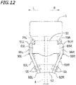
FIG. 12 is a back view schematically showing the main portion of the outboard motor according to an alternative embodiment. - Embodiments will now be described with reference to the drawings.
FIG. 1 shows awatercraft 10 including anoutboard motor 100 according to the present embodiment. The terms front, rear, left and right, as used in the description below, refers to these directions as viewed facing the forward direction of thewatercraft 10, while anaxis 7c of adrive shaft 7 to be described below extends vertically and theoutboard motor 100 is not inclined left and right relative to ahull 11. The designations F, B, L and R, as used in the figures, refer to front, rear, left and right, respectively. - The
watercraft 10 includes thehull 11, asteering wheel 12, aremote controller 13 and theoutboard motor 100. Theoutboard motor 100 is attached to the rear portion of thehull 11. - The
steering wheel 12 is provided for steering thehull 11. As the passenger of thewatercraft 10 operates thesteering wheel 12, theoutboard motor 100 rotates leftward or rightward relative to thehull 11. It is possible to shift gears of theoutboard motor 100. By operating theremote controller 13, the passenger can switch the state of theoutboard motor 100 between forward, backward and neutral. Theoutboard motor 100 includes anengine 1, and theengine 1 is provided with a throttle valve (not shown). By operating theremote controller 13, the passenger can adjust the opening of the throttle valve. By adjusting the opening of the throttle valve, it is possible to adjust the output power of theoutboard motor 100. -
FIG. 2 is a side view showing theoutboard motor 100. Theoutboard motor 100 includes an outboard motormain unit 101, asupport member 50 for supporting the outboard motormain unit 101, and anattachment member 70 for attaching thesupport member 50 to thehull 11. - The outboard motor
main unit 101 includes theengine 1, apropulsion unit 5 including apropeller 3, thedrive shaft 7 connected to theengine 1 and thepropulsion unit 5, and anupper case 20. Theengine 1 is arranged upward of theupper case 20. Thepropulsion unit 5 is arranged downward of theupper case 20 and is arranged downward of theengine 1. - The
engine 1 is an internal combustion engine that is driven through combustion of fuel such as gasoline or diesel oil. Theengine 1 is covered by acover 2. - The
drive shaft 7 is configured to transmit power output from theengine 1 to thepropulsion unit 5. Thedrive shaft 7 extends downward from theengine 1. Thedrive shaft 7 rotates by being driven by theengine 1. - The
propulsion unit 5 includes apropeller shaft 9 on which thepropeller 3 is provided, agear device 15 that links together thedrive shaft 7 and thepropeller shaft 9, and alower case 6. Thegear device 15 transmits the rotation of thedrive shaft 7 to thepropeller shaft 9 while decelerating the rotation. Although not shown in the figure, thegear device 15 includes a pinion gear, a forward bevel gear, a backward bevel gear and a dog clutch. A gear device well known in the art can be suitably used as thegear device 15. Thepropeller 3 rotates together with thepropeller shaft 9, thereby generating forward or backward propulsion. -
FIG. 3 is a perspective view showing theupper case 20, thesupport member 50 and theattachment member 70.FIG. 4 is a plan view showing theupper case 20, thesupport member 50 and theattachment member 70.FIG. 5 is a back view showing theupper case 20, thesupport member 50 and theattachment member 70. - As shown in
FIG. 2 , theupper case 20 is arranged between theengine 1 and thepropulsion unit 5. Theupper case 20 supports theengine 1 and also supports thepropulsion unit 5. As shown inFIG. 3 , theupper case 20 is composed of a plurality ofcase parts 21 to 30. Thecase parts 21 to 30 are formed separately from each other. That is, thecase parts 21 to 30 are separate parts. - The
case part 25 and thecase part 26 are formed in a flat plate shape. Thecase part 26 is arranged downward of thecase part 25. As shown inFIG. 2 , theengine 1 is attached to thecase part 25. Thepropulsion unit 6 is attached to thecase part 26. - As shown in
FIG. 3 , thecase part 21 and thecase part 22 oppose each other in a direction perpendicular to theaxis 7c of the drive shaft 7 (seeFIG. 2 ). Thedrive shaft 7 is arranged between thecase part 21 and thecase part 22. In the present embodiment, thecase part 22 is arranged rightward of thecase part 21. Thecase part 21 is arranged leftward of thedrive shaft 7, and thecase part 22 is arranged rightward of thedrive shaft 7. Throughholes 32 are formed in thecase part 21 and thecase part 22. The through holes 32 are open in a direction perpendicular to theaxis 7c of thedrive shaft 7. Here, the throughholes 32 are open leftward and rightward. - The
case part 29 is secured to the lower portion of thecase part 21. Thecase part 30 is secured to the lower portion of thecase part 22. Thecase part 29 and thecase part 30 are arranged upward of thecase part 26 and secured to thecase part 26. - The
case part 23 is connected to thecase part 21 and thecase part 22. Thecase part 23 extends in the left-right direction, bridging between the lower portion of thecase part 21 and the lower portion of thecase part 22. Thecase part 24 is arranged upward of thecase part 23. Thecase part 24 extends in the left-right direction, bridging between the upper portion of thecase part 21 and the upper portion of thecase part 22. Thecase part 24 is connected to thecase part 21, thecase part 22 and thecase part 25. As shown inFIG. 2 , a cylindricalupper steering shaft 61 is inserted through thecase part 24. A cylindricallower steering shaft 62 is inserted through thecase part 23. Thedrive shaft 7 is inserted through theupper steering shaft 61 and thelower steering shaft 62. Thedrive shaft 7 is arranged coaxial with theupper steering shaft 61 and thelower steering shaft 62. - As shown in
FIG. 3 , thecase part 28 is connected to thecase part 21, thecase part 22 and thecase part 25. Thecase part 27 is connected to thecase part 21, thecase part 29, thecase part 22, thecase part 30 and thecase part 26. - The
upper case 20 is obtained by assembling together thecase parts 21 to 30. There is no particular limitation on the manner of assembly of thecase parts 21 to 30. Some or all of thecase parts 21 to 30 may be attached together by means of fastening devices such as bolts or may be attached together by welding, or the like, without using fastening devices. - The
support member 50 is a member that horizontally rotatably supports the outboard motormain unit 101. Thesupport member 50 includes anupper support member 51 and alower support member 52. Theupper support member 51 supports the upper portion of theupper case 20. Thelower support member 52 supports the lower portion of theupper case 20. Theupper support member 51 and thelower support member 52 are separate from each other, and thelower support member 52 is spaced apart downward from theupper support member 51. Thecase part 24 is horizontally rotatably supported on theupper support member 51 by theupper steering shaft 61. Thecase part 23 is horizontally rotatably supported on thelower support member 52 by thelower steering shaft 62. Theupper steering shaft 61 and thelower steering shaft 62 horizontally rotatably connect theupper case 20 to thesupport member 50. In the present embodiment, the axes of theupper steering shaft 61 and thelower steering shaft 62 coincide with theaxis 7c of thedrive shaft 7. The outboard motormain unit 101 can rotate leftward and rightward about theaxis 7c. - The
attachment member 70 is attached to the rear portion of thehull 11. Thesupport member 50 is connected, by atilt shaft 65 extending in the left-right direction, to theattachment member 70. Thetilt shaft 65 vertically rotatably links thesupport member 50 to theattachment member 70. Here, theattachment member 70 is vertically rotatably connected to theupper support member 51 by thetilt shaft 65. - As shown in
FIG. 4 , theattachment member 70 includes aleft clamp bracket 70L, and aright clamp bracket 70R arranged rightward relative to theleft clamp bracket 70L. At least a portion of theupper support member 51 is sandwiched between theleft clamp bracket 70L and theright clamp bracket 70R. - As will be described below, the
tilt shaft 65 includes aleft tilt shaft 65L and aright tilt shaft 65R (seeFIG. 6 ). Theupper support member 51 includes aleft cover 54L that covers theleft tilt shaft 65L and aright cover 54R that covers theright tilt shaft 65R. Theleft cover 54L is arranged leftward of theleft clamp bracket 70L, and theright cover 54R is arranged rightward of theright clamp bracket 70R. - As shown in
FIG. 2 , aleft reinforcement member 90L is connected to theupper support member 51 and thelower support member 52. Theleft reinforcement member 90L is provided bridging between the left portion of theupper support member 51 and the left portion of thelower support member 52. Theleft reinforcement member 90L includes a leftupper connecting portion 91L connected to theupper support member 51 and a left lower connectingportion 92L connected to thelower support member 52. In the present embodiment, the leftupper connecting portion 91L is connected to theleft cover 54L of theupper support member 51. - A
right reinforcement member 90R is connected to theupper support member 51 and the lower support member 52 (seeFIG. 5 ).FIG. 6 is a plan view schematically showing theleft reinforcement member 90L, theright reinforcement member 90R, etc. Theright reinforcement member 90R is provided bridging between the right portion of theupper support member 51 and the right portion of thelower support member 52. Theright reinforcement member 90R includes the rightupper connecting portion 91R connected to theupper support member 51, and the right lower connectingportion 92R connected to thelower support member 52. In the present embodiment, as shown inFIG. 5 , the rightupper connecting portion 91R is connected to theright cover 54R of theupper support member 51. - As shown in
FIG. 6 , theupper support member 51 includes aleft side portion 51L located rightward of theleft clamp bracket 70L, and aright side portion 51R located leftward of theright clamp bracket 70R. Part or whole of theupper support member 51 is sandwiched between theleft clamp bracket 70L and theright clamp bracket 70R. The leftupper connecting portion 91L of theleft reinforcement member 90L is located leftward relative to theleft side portion 51L of theupper support member 51. The leftupper connecting portion 91L is located leftward relative to theleft clamp bracket 70L. The left lower connectingportion 92L is located downward relative to the leftupper connecting portion 91L. The rightupper connecting portion 91R of theright reinforcement member 90R is located rightward relative to theright side portion 51R of theupper support member 51. The rightupper connecting portion 91R is located rightward relative to theright clamp bracket 70R. The right lower connectingportion 92R is located downward relative to the rightupper connecting portion 91R. - The
left tilt shaft 65L rotatably links together theleft side portion 51L of theupper support member 51 and theleft clamp bracket 70L. Theright tilt shaft 65R rotatably links together theright side portion 51R of theupper support member 51 and theright clamp bracket 70R. In the present embodiment, theleft tilt shaft 65L and theright tilt shaft 65R are integrated with theupper support member 51. Theleft tilt shaft 65L, theright tilt shaft 65R and theupper support member 51 are a single part. Note however that there is no limitation thereto. Theleft tilt shaft 65L and theright tilt shaft 65R may be separate from theupper support member 51. Theleft tilt shaft 65L may be integral with or separate from theleft clamp bracket 70L. Theright tilt shaft 65R may be integral with or separate from theright clamp bracket 70R. - As shown in
FIG. 2 , thetilt cylinder 80 is connected to theattachment member 70 and thesupport member 50. Thetilt cylinder 80 is vertically rotatably connected to theattachment member 70 and thesupport member 50. Specifically, thetilt cylinder 80 includes arod 83 and acylinder 84. Afirst link portion 81 is provided at the upper end portion of therod 83. Thefirst link portion 81 is vertically rotatably linked to theattachment member 70. Asecond link portion 82 is provided at the lower end portion of thecylinder 84. Thesecond link portion 82 is vertically rotatably linked to thelower support member 52. The outboard motormain unit 101 rotates about thetilt shaft 65 as therod 83 extends and retracts. InFIG. 2 , the outboard motormain unit 101 rotates counterclockwise when therod 83 extends, and rotates clockwise when therod 83 retracts. - It is preferred that the
left reinforcement member 90L and theright reinforcement member 90R are arranged so as to straddle in the up-down direction at least one of thefirst link portion 81 and thesecond link portion 82 of thetilt cylinder 80. That is, it is preferred that at least one of thefirst link portion 81 and thesecond link portion 82 of thetilt cylinder 80 is arranged downward relative to anupper end 90t of theleft reinforcement member 90L and theright reinforcement member 90R and upward relative to alower end 90b thereof. - In the present embodiment, the
left reinforcement member 90L and theright reinforcement member 90R are arranged so as to straddle in the up-down direction both of thefirst link portion 81 and thesecond link portion 82 of thetilt cylinder 80. That is, thefirst link portion 81 and thesecond link portion 82 of thetilt cylinder 80 are arranged downward relative to theupper end 90t of theleft reinforcement member 90L and theright reinforcement member 90R and upward relative to thelower end 90b thereof. - As viewed from the side of the
outboard motor 100, theleft reinforcement member 90L and theright reinforcement member 90R are slant relative to thedrive shaft 7. The left lower connectingportion 92L of theleft reinforcement member 90L is arranged rearward and downward relative to the leftupper connecting portion 91L. The right lower connectingportion 92R of theright reinforcement member 90R is arranged rearward and downward relative to the rightupper connecting portion 91R. Theleft reinforcement member 90L and theright reinforcement member 90R extend rearward and downward. Therefore, theleft reinforcement member 90L and theright reinforcement member 90R can suitably support the load in the up-down direction and the front-rear direction. Note that while theleft reinforcement member 90L and theright reinforcement member 90R are entirely slant relative to thedrive shaft 7 as viewed from the side of theoutboard motor 100 in the present embodiment, theleft reinforcement member 90L and theright reinforcement member 90R may be partially slant relative to thedrive shaft 7. - As shown in
FIG. 5 , part or whole of theleft reinforcement member 90L preferably extends downward and rightward. Part or whole of theright reinforcement member 90R preferably extends downward and leftward. In other words, theleft reinforcement member 90L preferably includes aslant portion 93L extending downward and rightward, and theright reinforcement member 90R preferably includes aslant portion 93R extending downward and leftward. In the present embodiment, the entirety of theleft reinforcement member 90L extends downward and rightward. The entirety of theright reinforcement member 90R extends downward and leftward. - While there is no particular limitation on the shape of the
left reinforcement member 90L and theright reinforcement member 90R, theleft reinforcement member 90L and theright reinforcement member 90R are formed in a plate shape. The dimension of theleft reinforcement member 90L and theright reinforcement member 90R in the left-right direction is smaller than that in the front-rear direction and that in the up-down direction. As shown inFIG. 2 , the dimension of theleft reinforcement member 90L and theright reinforcement member 90R in the front-rear direction is larger than the outer diameter of thecylinder 84 of thetilt cylinder 80. Theleft reinforcement member 90L and theright reinforcement member 90R are partly located forward relative to the axis of thetilt shaft 65. Theleft reinforcement member 90L includes bolt holes 95 through which bolts 55 (not shown inFIG. 2 , seeFIG. 6 ) are inserted for attaching theleft reinforcement member 90L to theleft cover 54L. Although not shown in the figure, theright reinforcement member 90R similarly includes bolt holes. In addition to the bolt holes 95, theleft reinforcement member 90L and theright reinforcement member 90R includesholes 94 that run through in the left-right direction. As opposed to the bolt holes 95, theholes 94 are always open without being closed. Theholes 94 are formed in order to reduce the weight of theleft reinforcement member 90L and theright reinforcement member 90R. While the number ofholes 94 is four herein, there is no particular limitation on the number ofholes 94. - The
outboard motor 100 is configured as described above. Next, various advantageous effects of theoutboard motor 100 according to the present embodiment will be described. - While navigating the
watercraft 10, a load in the lateral direction (lateral load) may be applied to a lower portion of the outboard motormain unit 101. For example, when thewatercraft 10 turns, leftward or rightward water pressure may be applied to thepropulsion unit 5. Thepropulsion unit 5 is supported by theupper case 20, and theupper case 20 is supported by thesupport member 50. When a lateral load is applied to thepropulsion unit 5, the lateral load is transmitted to theupper case 20. A portion of the lateral load transmitted to theupper case 20 is transmitted to thesupport member 50. In the present embodiment, theupper case 20 is supported by theupper support member 51 and thelower support member 52. Therefore, when a lateral load is applied to theupper case 20, a portion of the lateral load is transmitted to theupper support member 51 and thelower support member 52. Attempting to support the lateral load with only theupper support member 51 and thelower support member 52 results in a need to increase the mechanical strength of theupper support member 51 and thelower support member 52 against lateral loads, and hence to increase the size and the weight of theupper support member 51 and thelower support member 52. - However, with the
outboard motor 100 according to the present embodiment, theleft reinforcement member 90L and theright reinforcement member 90R are connected to theupper support member 51 and thelower support member 52. Thesupport member 50 is reinforced by theleft reinforcement member 90L and theright reinforcement member 90R. Particularly, the leftupper connecting portion 91L of theleft reinforcement member 90L is located leftward relative to theleft side portion 51L of theupper support member 51, and the rightupper connecting portion 91R of theright reinforcement member 90R is located rightward relative to theright side portion 51R of theupper support member 51. Therefore, with theleft reinforcement member 90L and theright reinforcement member 90R, it is possible to efficiently increase the mechanical strength of thesupport member 50 against lateral loads. A portion of the lateral load that is transmitted from thepropulsion unit 5 to theupper case 20 is transmitted from thelower support member 52 to thehull 11 via theleft reinforcement member 90L, theright reinforcement member 90R, theupper support member 51 and theattachment member 70. A portion of the lateral load that is transmitted from thepropulsion unit 5 to theupper case 20 is transmitted directly to theupper support member 51 from thelower support member 52. This reduces the lateral load applied to theupper case 20. It is possible to prevent an increase in size and weight of theupper case 20. Therefore, with theoutboard motor 100 according to the present embodiment, it is possible to increase the mechanical strength against lateral loads while preventing an increase in size and weight of thesupport member 50. - In the present embodiment, as shown in
FIG. 6 , the leftupper connecting portion 91L of theleft reinforcement member 90L is located leftward relative to theleft clamp bracket 70L, and the rightupper connecting portion 91R of theright reinforcement member 90R is located rightward relative to theright clamp bracket 70R. The leftupper connecting portion 91L is located more leftward. The rightupper connecting portion 91R is located more rightward. Therefore, it is possible to more effectively increase the mechanical strength of thesupport member 50 against lateral loads. - As shown in
FIG. 2 , at least one of thefirst link portion 81 and thesecond link portion 82 of thetilt cylinder 80 is arranged downward relative to theupper end 90t of theleft reinforcement member 90L and theright reinforcement member 90R and upward relative to thelower end 90b thereof. In the present embodiment, thefirst link portion 81 and thesecond link portion 82 of thetilt cylinder 80 is arranged downward relative to theupper end 90t of theleft reinforcement member 90L and theright reinforcement member 90R and upward relative to thelower end 90b thereof. Therefore, when a lateral load is applied to thepropulsion unit 5, it is possible to prevent the lateral load from being transmitted to thetilt cylinder 80 via theupper case 20 and thesupport member 50. It is possible to prevent a large lateral load from being applied to thetilt cylinder 80. Theupper end 90t of theleft reinforcement member 90L and theright reinforcement member 90R is located upward relative to thefirst link portion 81 of thetilt cylinder 80, and thelower end 90b thereof is located downward relative to thesecond link portion 82 of thetilt cylinder 80. Thus, the dimension of theleft reinforcement member 90L and theright reinforcement member 90R in the up-down direction is relatively large. Therefore, even if the dimension of thesupport member 50 in the up-down direction is relatively large, it is possible to sufficiently increase the mechanical strength of thesupport member 50 against lateral loads. - The left lower connecting
portion 92L of theleft reinforcement member 90L is arranged rearward relative to the leftupper connecting portion 91L, and the right lower connectingportion 92R of theright reinforcement member 90R is arranged rearward relative to the rightupper connecting portion 91R. Theleft reinforcement member 90L and theright reinforcement member 90R extend downward and rearward. Therefore, theleft reinforcement member 90L and theright reinforcement member 90R can sufficiently support a load in the left-right direction (i.e., a lateral load), and can also support a load in the up-down direction and the front-rear direction. Thus, it is possible to increase the mechanical strength of thesupport member 50. - As shown in
FIG. 5 , theleft reinforcement member 90L includes theslant portion 93L extending downward and rightward. Theright reinforcement member 90R includes theslant portion 93R extending downward and leftward. Theleft reinforcement member 90L has a significant mechanical strength against loads upward and leftward. Theright reinforcement member 90R has a significant mechanical strength against loads upward and rightward. Therefore, it is possible to increase the mechanical strength of thesupport member 50 against lateral loads. - While the
support member 50 may be an integral member, it includes in the present embodiment theupper support member 51 and thelower support member 52, which are separate from each other. Thelower support member 52 is spaced apart downward from theupper support member 51. Thesupport member 50 includes no member that links together theupper support member 51 and thelower support member 52. Therefore, as compared with a case where thesupport member 50 is an integral member, it is possible to reduce the size and the weight of thesupport member 50. The leftupper connecting portion 91L of theleft reinforcement member 90L and the rightupper connecting portion 91R of theright reinforcement member 90R are connected to theupper support member 51, and the left lower connectingportion 92L of theleft reinforcement member 90L and the right lower connectingportion 92R of theright reinforcement member 90R are connected to thelower support member 52. Thus, although thesupport member 50 includes theupper support member 51 and thelower support member 52, which are separate from each other, it is possible, with theleft reinforcement member 90L and theright reinforcement member 90R, to sufficiently increase the mechanical strength of thesupport member 50 against lateral loads. - While there is no particular limitation on the shape of the
left reinforcement member 90L and theright reinforcement member 90R, theleft reinforcement member 90L and theright reinforcement member 90R are formed in a plate shape in the present embodiment. Therefore, it is possible to easily manufacture theleft reinforcement member 90L and theright reinforcement member 90R. - The
left reinforcement member 90L and theright reinforcement member 90R includes theholes 94 that run through in the left-right direction. Therefore, it is possible to reduce the weight of theleft reinforcement member 90L and theright reinforcement member 90R. - While one embodiment has been described above, the embodiment is merely illustrative, and various alternative embodiments are possible. Next, alternative embodiments will be described briefly.
- As shown in
FIG. 7 , theoutboard motor 100 may include alateral reinforcement member 90C connected to theleft reinforcement member 90L and theright reinforcement member 90R. Thelateral reinforcement member 90C is provided bridging between theleft reinforcement member 90L and theright reinforcement member 90R. Thelateral reinforcement member 90C extends in the left-right direction. Note however that there is no limitation thereto. Thelateral reinforcement member 90C may extend leftward and rearward or may extend rightward and rearward. Thelateral reinforcement member 90C may extend downward and rearward or may extend upward and rearward. Thelateral reinforcement member 90C may extend straight or may be curved. Thelateral reinforcement member 90C may be curved or may be bent, and there is no particular limitation on the method for connecting thelateral reinforcement member 90C to theleft reinforcement member 90L and theright reinforcement member 90R. As shown inFIG. 7 , thelateral reinforcement member 90C may be connected to theleft reinforcement member 90L and theright reinforcement member 90R by means of fastening devices such as thebolts 55, or may be connected thereto by welding, or the like, without using fastening devices. By providing thelateral reinforcement member 90C on theleft reinforcement member 90L and theright reinforcement member 90R, it is possible to further increase the mechanical strength of thesupport member 50 against lateral loads. - As shown in
FIG. 8 , theoutboard motor 100 may include thesteering actuator 85 for rotating the outboard motormain unit 101 left and right. Here, the steeringactuator 85 includes acylinder 85C, aleft rod 85L extending leftward from thecylinder 85C, and aright rod 85R extending rightward from thecylinder 85C. Thecylinder 85C and a steeringshaft 60 are linked together by alink shaft 86 extending in the vertical direction. InFIG. 8 , the steeringshaft 60 rotates clockwise when theleft rod 85L extends and theright rod 85R retracts, and the steeringshaft 60 rotates counterclockwise when theright rod 85R extends and theleft rod 85L retracts. Note that thecylinder 85C may be linked to theupper steering shaft 61 or may be linked to thelower steering shaft 62. A middle steering shaft (not shown) that links together theupper steering shaft 61 and thelower steering shaft 62 may be provided between theupper steering shaft 61 and thelower steering shaft 62, and the middle steering shaft may be linked to thecylinder 85C. - At least a portion of the
steering actuator 85 is preferably arranged between theleft reinforcement member 90L and theright reinforcement member 90R. Then, the space between theleft reinforcement member 90L and theright reinforcement member 90R can be used as an installation space for thesteering actuator 85. It is possible to reduce the size of theoutboard motor 100. - The steering
actuator 85 may serve also as a lateral reinforcement member. For example, the left end portion of theleft rod 85L may be connected to theleft reinforcement member 90L, and the right end portion of theright rod 85R may be connected to theright reinforcement member 90R. Then, theleft rod 85L, thecylinder 85C and theright rod 85R serve as a lateral reinforcement member bridging between theleft reinforcement member 90L and theright reinforcement member 90R. Thus, by using thesteering actuator 85 as a lateral reinforcement member, it is possible to increase the mechanical strength of thesupport member 50 against lateral loads without increasing the number of components. - As shown in
FIG. 9 , theleft rod 85L and theleft tilt shaft 65L may be arranged coaxial with each other, and theright rod 85R and theright tilt shaft 65R may be arranged coaxial with each other. The steeringactuator 85 may be connected to the leftupper connecting portion 91L of theleft reinforcement member 90L and to the rightupper connecting portion 91R of theright reinforcement member 90R. Note thatFIG. 9 does not show a mechanism for linking together thecylinder 85C and the steeringshaft 60. - As shown in
FIG. 10 , the leftupper connecting portion 91L of theleft reinforcement member 90L may be attached to theleft tilt shaft 65L. The rightupper connecting portion 91R of theright reinforcement member 90R may be attached to theright tilt shaft 65R. As shown inFIG. 11 , the leftupper connecting portion 91L of theleft reinforcement member 90L includes ahole 96 through which theleft tilt shaft 65L is inserted. Similarly, the rightupper connecting portion 91R of theright reinforcement member 90R may include a hole through which theright tilt shaft 65R is inserted. By inserting theleft tilt shaft 65L through thehole 96 of the leftupper connecting portion 91L and inserting theright tilt shaft 65R through the hole of the rightupper connecting portion 91R, it is possible to easily attach theleft reinforcement member 90L and theright reinforcement member 90R to theupper support member 51. - As shown in
FIG. 10 , the leftupper connecting portion 91L of theleft reinforcement member 90L may be arranged rightward of theleft clamp bracket 70L. The rightupper connecting portion 91R of theright reinforcement member 90R may be arranged leftward of theright clamp bracket 70R. Alternatively, the leftupper connecting portion 91L may be arranged leftward of theleft clamp bracket 70L and the rightupper connecting portion 91R may be arranged rightward of theright clamp bracket 70R. - As shown in
FIG. 12 , a portion of theleft reinforcement member 90L may extend in the vertical direction and another portion thereof may extend downward and rightward. A portion of theright reinforcement member 90R may extend in the vertical direction and another portion may extend downward and leftward. In other words, theleft reinforcement member 90L may include avertical portion 96L extending in the vertical direction, and theslant portion 93L extending downward and rightward from the lower end of thevertical portion 96L. Theright reinforcement member 90R may include avertical portion 96R extending in the vertical direction, and theslant portion 93R extending downward and leftward from the lower end of thevertical portion 96R. - The left
upper connecting portion 91L of theleft reinforcement member 90L may be connected to any of theleft cover 54L, theleft tilt shaft 65L and theleft side portion 51L of theupper support member 51, or may be connected to a portion of theupper support member 51 other than theleft side portion 51L. The rightupper connecting portion 91R of theright reinforcement member 90R may be connected to any of theright cover 54R, theright tilt shaft 65R and theright side portion 51R of theupper support member 51, or may be connected to a portion of theupper support member 51 other than theright side portion 51R. - While the
left reinforcement member 90L and theright reinforcement member 90R are formed in a plate shape in the embodiment described above, there is no particular limitation thereto. For example, theleft reinforcement member 90L and theright reinforcement member 90R may be formed in a rod shape. Theleft reinforcement member 90L and theright reinforcement member 90R may or may not be shaped in left-right symmetry. - The
holes 94 of theleft reinforcement member 90L and theright reinforcement member 90R are not always necessary. Theholes 94 may be absent. - The
case part 21 and thecase part 22 of theupper case 20 do not need to oppose each other in the left-right direction. Thecase part 21 and thecase part 22 of theupper case 20 may oppose each other in the front-rear direction. Theupper case 20 does not need to have a frame structure obtained by assembling together thecase parts 21 to 30. Theupper case 20 may be formed in a closed tubular shape. - As shown in
FIG. 2 , in the embodiment described above, thetilt cylinder 80 is arranged so that therod 83 extends upward and forward. However, there is no limitation on the arrangement of thetilt cylinder 80. For example, thetilt cylinder 80 may be arranged so that therod 83 extends upward and rearward. For example, the lower end portion of thecylinder 84 may be vertically rotatably linked to theattachment member 70, and the upper end portion of therod 83 may be vertically rotatably linked to theupper support member 51. In this case, the lower end portion of thecylinder 84 serves as the first link portion, and the upper end portion of therod 83 serves as the second link portion. In this embodiment or the embodiment described above (seeFIG. 2 ), the positions of therod 83 and thecylinder 84 may be switched around. - 1: Engine, 5: Propulsion unit, 7: Drive shaft, 11: Hull, 20: Upper case, 50: Support member, 51: Upper support member, 51L: Left side portion, 51R: Right side portion, 52: Lower support member, 60: Steering shaft, 61: Upper steering shaft, 62: Lower steering shaft, 65: Tilt shaft, 65L: Left tilt shaft, 65R: Right tilt shaft, 70: Attachment member, 70L: Left clamp bracket, 70R: Right clamp bracket, 80: Tilt cylinder, 81: First link portion, 82: Second link portion, 85: Steering actuator, 90C: Lateral reinforcement member, 90L: Left reinforcement member, 90R: Right reinforcement member, 91L: Left upper connecting portion, 91R: Right upper connecting portion, 92L: Left lower connecting portion, 92R: Right lower connecting portion, 93L: Slant portion, 93R: Slant portion, 94: Hole, 100: Outboard motor, 101: Outboard motor main unit
Claims (14)
- An outboard motor (100) configured to be attachable to a watercraft (10) and especially with regard to the outboard motor (100) attached the watercraft (10), the comprising:an outboard motor main unit (101) including an engine (1), a propulsion unit (5) arranged downward of the engine (1), and a drive shaft (7) connected to the engine (1) and the propulsion unit (5);an attachment member (70) configured to be attached to a hull (11) of the watercraft (10); anda support member (50) vertically rotatably connected to the attachment member (70) and horizontally rotatably supporting the outboard motor main unit (101), wherein:the attachment member (70) includes a left clamp bracket (70L), and a right clamp bracket (70R) arranged rightward relative to the left clamp bracket (70L);the support member (50) includes a left side portion (51L) located rightward of the left clamp bracket (70L) and a right side portion (51R) located leftward of the right clamp bracket (70R), and is sandwiched between the left clamp bracket (70L) and the right clamp bracket (70R); andthe outboard motor (100) comprises:a left tilt shaft (65L) that vertically rotatably links together the left side portion (51L) of the support member (50) and the left clamp bracket (70L);a right tilt shaft (65R) that vertically rotatably links together the right side portion (51R) of the support member (50) and the right clamp bracket (70R);a left reinforcement member (90L) that includes a left upper connecting portion (91L) connected to the support member (50) and located leftward relative to the left side portion (51L) of the support member (50), and a left lower connecting portion (92L) connected to the support member (50) and located downward relative to the left upper connecting portion (91L); anda right reinforcement member (90R) that includes a right upper connecting portion (91R) connected to the support member (50) and located rightward relative to the right side portion (51R) of the support member (50), and a right lower connecting portion (92R) connected to the support member (50) and located downward relative to the right upper connecting portion (91R).
- The outboard motor (100) according to claim 1, comprising:a tilt cylinder (80) including a first link portion (81) vertically rotatably linked to the attachment member (70) and a second link portion (82) vertically rotatably linked to the support member (50),wherein at least one of the first link portion (81) and the second link portion (82) of the tilt cylinder (80) is arranged downward relative to an upper end (90t) of the left reinforcement member (90L) and the right reinforcement member (90R) and upward relative to a lower end (90b) thereof.
- The outboard motor (100) according to claim 2, wherein both of the first link portion (81) and the second link portion (82) of the tilt cylinder (80) are arranged downward relative to an upper end (90t) of the left reinforcement member (90L) and the right reinforcement member (90R) and upward relative to a lower end (90b) thereof.
- The outboard motor (100) according to any one of claims 1 to 3, wherein:the left lower connecting portion (92L) of the left reinforcement member (90L) is arranged rearward relative to the left upper connecting portion (91L); andthe right lower connecting portion (92R) of the right reinforcement member (90R) is arranged rearward relative to the right upper connecting portion (91R).
- The outboard motor (100) according to any one of claims 1 to 4, wherein:the support member (50) includes an upper support member (51) sandwiched between the left clamp bracket (70L) and the right clamp bracket (70R), and a lower support member (52) spaced apart downward from the upper support member (51);the left upper connecting portion (91L) of the left reinforcement member (90L) and the right upper connecting portion (91R) of the right reinforcement member (90R) are connected to the upper support member (51); andthe left lower connecting portion (92L) of the left reinforcement member (90L) and the right lower connecting portion (92R) of the right reinforcement member (90R) are connected to the lower support member (52).
- The outboard motor (100) according to any one of claims 1 to 5, wherein:the left upper connecting portion (91L) of the left reinforcement member (90L) is located leftward relative to the left clamp bracket (70L); andthe right upper connecting portion (91R) of the right reinforcement member (90R) is located rightward relative to the right clamp bracket (70R).
- The outboard motor (100) according to any one of claims 1 to 6, wherein:the left upper connecting portion (91L) of the left reinforcement member (90L) is attached to the left tilt shaft (65L); andthe right upper connecting portion (91R) of the right reinforcement member (90R) is attached to the right tilt shaft (65R).
- The outboard motor (100) according to any one of claims 1 to 7, wherein:the left reinforcement member (90L) includes a slant portion (93L) extending downward and rightward; andthe right reinforcement member (90R) includes a slant portion (93R) extending downward and leftward.
- The outboard motor (100) according to any one of claims 1 to 8, comprising a lateral reinforcement member (90C) connected to the left reinforcement member (90L) and the right reinforcement member (90R) and bridging between the left reinforcement member (90L) and the right reinforcement member (90R).
- The outboard motor (100) according to claim 9, wherein the lateral reinforcement member (90C) extends in a left-right direction.
- The outboard motor (100) according to any one of claims 1 to 10, comprising:
a steering actuator (85) that rotates the outboard motor main unit (101) left and right, wherein at least a portion of the steering actuator (85) is arranged between the left reinforcement member (90L) and the right reinforcement member (90R). - The outboard motor (100) according to any one of claims 1 to 11, wherein part or whole of the left reinforcement member (90L) and the right reinforcement member (90R) extends downward and rearward and is slant relative to the drive shaft (7) as viewed from a side.
- The outboard motor (100) according to any one of claims 1 to 12, wherein the left reinforcement member (90L) and the right reinforcement member (90R) are formed in a plate shape.
- The outboard motor (100) according to any one of claims 1 to 13, wherein the left reinforcement member (90L) and the right reinforcement member (90R) include holes (94) that run through in a left-right direction.
Applications Claiming Priority (1)
| Application Number | Priority Date | Filing Date | Title |
|---|---|---|---|
| JP2020212112A JP2022098623A (en) | 2020-12-22 | 2020-12-22 | Outboard engine |
Publications (2)
| Publication Number | Publication Date |
|---|---|
| EP4019392A1 true EP4019392A1 (en) | 2022-06-29 |
| EP4019392B1 EP4019392B1 (en) | 2024-04-10 |
Family
ID=78078114
Family Applications (1)
| Application Number | Title | Priority Date | Filing Date |
|---|---|---|---|
| EP21200945.0A Active EP4019392B1 (en) | 2020-12-22 | 2021-10-05 | Outboard motor |
Country Status (3)
| Country | Link |
|---|---|
| US (1) | US12012194B2 (en) |
| EP (1) | EP4019392B1 (en) |
| JP (1) | JP2022098623A (en) |
Families Citing this family (1)
| Publication number | Priority date | Publication date | Assignee | Title |
|---|---|---|---|---|
| JP7350038B2 (en) | 2021-11-11 | 2023-09-25 | ヤマハ発動機株式会社 | Outboard motor suspension structure, outboard motor |
Citations (4)
| Publication number | Priority date | Publication date | Assignee | Title |
|---|---|---|---|---|
| US3486724A (en) * | 1968-04-16 | 1969-12-30 | Raymond Adamski | Outboard motor support |
| SE343809B (en) * | 1971-01-04 | 1972-03-20 | Mathewson Corp | |
| US20090170384A1 (en) * | 2007-07-02 | 2009-07-02 | Brunswick Corporation | Support system for a marine propulsion device |
| JP2018002004A (en) | 2016-07-04 | 2018-01-11 | ヤマハ発動機株式会社 | Outboard engine |
Family Cites Families (2)
| Publication number | Priority date | Publication date | Assignee | Title |
|---|---|---|---|---|
| JPH01311987A (en) * | 1988-06-13 | 1989-12-15 | Sanshin Ind Co Ltd | Outboard engine |
| JP5982721B2 (en) * | 2013-01-15 | 2016-08-31 | ヤマハ発動機株式会社 | Suspension device for outboard motor and ship equipped with the device |
-
2020
- 2020-12-22 JP JP2020212112A patent/JP2022098623A/en active Pending
-
2021
- 2021-10-05 EP EP21200945.0A patent/EP4019392B1/en active Active
- 2021-12-10 US US17/547,282 patent/US12012194B2/en active Active
Patent Citations (4)
| Publication number | Priority date | Publication date | Assignee | Title |
|---|---|---|---|---|
| US3486724A (en) * | 1968-04-16 | 1969-12-30 | Raymond Adamski | Outboard motor support |
| SE343809B (en) * | 1971-01-04 | 1972-03-20 | Mathewson Corp | |
| US20090170384A1 (en) * | 2007-07-02 | 2009-07-02 | Brunswick Corporation | Support system for a marine propulsion device |
| JP2018002004A (en) | 2016-07-04 | 2018-01-11 | ヤマハ発動機株式会社 | Outboard engine |
Also Published As
| Publication number | Publication date |
|---|---|
| US12012194B2 (en) | 2024-06-18 |
| US20220194536A1 (en) | 2022-06-23 |
| EP4019392B1 (en) | 2024-04-10 |
| JP2022098623A (en) | 2022-07-04 |
Similar Documents
| Publication | Publication Date | Title |
|---|---|---|
| JP2010158926A (en) | Outboard motor | |
| EP3569488B1 (en) | Outboard motor | |
| US9233743B2 (en) | Steering device of outboard motor | |
| US6883451B2 (en) | Outboard motor steering system | |
| EP4019392B1 (en) | Outboard motor | |
| JP2007055310A (en) | Outboard motor | |
| US20230174212A1 (en) | Drive arrangement for a marine vessel | |
| JP2005313822A (en) | Outboard motor operating device | |
| US12195155B2 (en) | Outboard motor | |
| JP7147349B2 (en) | Outboard motor | |
| JP2018108766A (en) | Outboard motor | |
| JP4935174B2 (en) | Outboard motor shift device | |
| JP2020168889A (en) | Ship maneuvering system | |
| JP3750883B2 (en) | Outboard motor | |
| JP4183806B2 (en) | Power tilt device for outboard motor | |
| JP3867055B2 (en) | Outboard motor steering system | |
| JP4713631B2 (en) | Outboard motor | |
| US12384502B2 (en) | Outboard motor and boat | |
| JP2018002004A (en) | Outboard engine | |
| US20260054813A1 (en) | Marine propulsion device | |
| JP5285562B2 (en) | Power steering device for small ships | |
| JP2012254702A (en) | Shift apparatus of outboard motor | |
| US20240208628A1 (en) | Outboard motor | |
| JPS609097Y2 (en) | Support structure of steering shaft in riding agricultural machinery | |
| JP2004218812A (en) | Outboard motor shift change device |
Legal Events
| Date | Code | Title | Description |
|---|---|---|---|
| PUAI | Public reference made under article 153(3) epc to a published international application that has entered the european phase |
Free format text: ORIGINAL CODE: 0009012 |
|
| STAA | Information on the status of an ep patent application or granted ep patent |
Free format text: STATUS: THE APPLICATION HAS BEEN PUBLISHED |
|
| AK | Designated contracting states |
Kind code of ref document: A1 Designated state(s): AL AT BE BG CH CY CZ DE DK EE ES FI FR GB GR HR HU IE IS IT LI LT LU LV MC MK MT NL NO PL PT RO RS SE SI SK SM TR |
|
| STAA | Information on the status of an ep patent application or granted ep patent |
Free format text: STATUS: REQUEST FOR EXAMINATION WAS MADE |
|
| 17P | Request for examination filed |
Effective date: 20221006 |
|
| RBV | Designated contracting states (corrected) |
Designated state(s): AL AT BE BG CH CY CZ DE DK EE ES FI FR GB GR HR HU IE IS IT LI LT LU LV MC MK MT NL NO PL PT RO RS SE SI SK SM TR |
|
| GRAP | Despatch of communication of intention to grant a patent |
Free format text: ORIGINAL CODE: EPIDOSNIGR1 |
|
| STAA | Information on the status of an ep patent application or granted ep patent |
Free format text: STATUS: GRANT OF PATENT IS INTENDED |
|
| INTG | Intention to grant announced |
Effective date: 20240115 |
|
| GRAS | Grant fee paid |
Free format text: ORIGINAL CODE: EPIDOSNIGR3 |
|
| GRAA | (expected) grant |
Free format text: ORIGINAL CODE: 0009210 |
|
| STAA | Information on the status of an ep patent application or granted ep patent |
Free format text: STATUS: THE PATENT HAS BEEN GRANTED |
|
| AK | Designated contracting states |
Kind code of ref document: B1 Designated state(s): AL AT BE BG CH CY CZ DE DK EE ES FI FR GB GR HR HU IE IS IT LI LT LU LV MC MK MT NL NO PL PT RO RS SE SI SK SM TR |
|
| REG | Reference to a national code |
Ref country code: GB Ref legal event code: FG4D |
|
| REG | Reference to a national code |
Ref country code: CH Ref legal event code: EP |
|
| REG | Reference to a national code |
Ref country code: DE Ref legal event code: R096 Ref document number: 602021011556 Country of ref document: DE |
|
| REG | Reference to a national code |
Ref country code: IE Ref legal event code: FG4D Ref country code: DE Ref legal event code: R082 Ref document number: 602021011556 Country of ref document: DE |
|
| P01 | Opt-out of the competence of the unified patent court (upc) registered |
Free format text: CASE NUMBER: APP_37588/2024 Effective date: 20240624 |
|
| REG | Reference to a national code |
Ref country code: LT Ref legal event code: MG9D |
|
| REG | Reference to a national code |
Ref country code: NL Ref legal event code: MP Effective date: 20240410 |
|
| REG | Reference to a national code |
Ref country code: AT Ref legal event code: MK05 Ref document number: 1674674 Country of ref document: AT Kind code of ref document: T Effective date: 20240410 |
|
| PG25 | Lapsed in a contracting state [announced via postgrant information from national office to epo] |
Ref country code: NL Free format text: LAPSE BECAUSE OF FAILURE TO SUBMIT A TRANSLATION OF THE DESCRIPTION OR TO PAY THE FEE WITHIN THE PRESCRIBED TIME-LIMIT Effective date: 20240410 |
|
| PG25 | Lapsed in a contracting state [announced via postgrant information from national office to epo] |
Ref country code: NL Free format text: LAPSE BECAUSE OF FAILURE TO SUBMIT A TRANSLATION OF THE DESCRIPTION OR TO PAY THE FEE WITHIN THE PRESCRIBED TIME-LIMIT Effective date: 20240410 |
|
| PG25 | Lapsed in a contracting state [announced via postgrant information from national office to epo] |
Ref country code: IS Free format text: LAPSE BECAUSE OF FAILURE TO SUBMIT A TRANSLATION OF THE DESCRIPTION OR TO PAY THE FEE WITHIN THE PRESCRIBED TIME-LIMIT Effective date: 20240810 |
|
| PG25 | Lapsed in a contracting state [announced via postgrant information from national office to epo] |
Ref country code: BG Free format text: LAPSE BECAUSE OF FAILURE TO SUBMIT A TRANSLATION OF THE DESCRIPTION OR TO PAY THE FEE WITHIN THE PRESCRIBED TIME-LIMIT Effective date: 20240410 |
|
| PG25 | Lapsed in a contracting state [announced via postgrant information from national office to epo] |
Ref country code: HR Free format text: LAPSE BECAUSE OF FAILURE TO SUBMIT A TRANSLATION OF THE DESCRIPTION OR TO PAY THE FEE WITHIN THE PRESCRIBED TIME-LIMIT Effective date: 20240410 Ref country code: FI Free format text: LAPSE BECAUSE OF FAILURE TO SUBMIT A TRANSLATION OF THE DESCRIPTION OR TO PAY THE FEE WITHIN THE PRESCRIBED TIME-LIMIT Effective date: 20240410 |
|
| PG25 | Lapsed in a contracting state [announced via postgrant information from national office to epo] |
Ref country code: GR Free format text: LAPSE BECAUSE OF FAILURE TO SUBMIT A TRANSLATION OF THE DESCRIPTION OR TO PAY THE FEE WITHIN THE PRESCRIBED TIME-LIMIT Effective date: 20240711 |
|
| PG25 | Lapsed in a contracting state [announced via postgrant information from national office to epo] |
Ref country code: PT Free format text: LAPSE BECAUSE OF FAILURE TO SUBMIT A TRANSLATION OF THE DESCRIPTION OR TO PAY THE FEE WITHIN THE PRESCRIBED TIME-LIMIT Effective date: 20240812 |
|
| PG25 | Lapsed in a contracting state [announced via postgrant information from national office to epo] |
Ref country code: ES Free format text: LAPSE BECAUSE OF FAILURE TO SUBMIT A TRANSLATION OF THE DESCRIPTION OR TO PAY THE FEE WITHIN THE PRESCRIBED TIME-LIMIT Effective date: 20240410 |
|
| PG25 | Lapsed in a contracting state [announced via postgrant information from national office to epo] |
Ref country code: AT Free format text: LAPSE BECAUSE OF FAILURE TO SUBMIT A TRANSLATION OF THE DESCRIPTION OR TO PAY THE FEE WITHIN THE PRESCRIBED TIME-LIMIT Effective date: 20240410 |
|
| PG25 | Lapsed in a contracting state [announced via postgrant information from national office to epo] |
Ref country code: PL Free format text: LAPSE BECAUSE OF FAILURE TO SUBMIT A TRANSLATION OF THE DESCRIPTION OR TO PAY THE FEE WITHIN THE PRESCRIBED TIME-LIMIT Effective date: 20240410 |
|
| PG25 | Lapsed in a contracting state [announced via postgrant information from national office to epo] |
Ref country code: LV Free format text: LAPSE BECAUSE OF FAILURE TO SUBMIT A TRANSLATION OF THE DESCRIPTION OR TO PAY THE FEE WITHIN THE PRESCRIBED TIME-LIMIT Effective date: 20240410 |
|
| PG25 | Lapsed in a contracting state [announced via postgrant information from national office to epo] |
Ref country code: PT Free format text: LAPSE BECAUSE OF FAILURE TO SUBMIT A TRANSLATION OF THE DESCRIPTION OR TO PAY THE FEE WITHIN THE PRESCRIBED TIME-LIMIT Effective date: 20240812 Ref country code: PL Free format text: LAPSE BECAUSE OF FAILURE TO SUBMIT A TRANSLATION OF THE DESCRIPTION OR TO PAY THE FEE WITHIN THE PRESCRIBED TIME-LIMIT Effective date: 20240410 Ref country code: NO Free format text: LAPSE BECAUSE OF FAILURE TO SUBMIT A TRANSLATION OF THE DESCRIPTION OR TO PAY THE FEE WITHIN THE PRESCRIBED TIME-LIMIT Effective date: 20240710 Ref country code: LV Free format text: LAPSE BECAUSE OF FAILURE TO SUBMIT A TRANSLATION OF THE DESCRIPTION OR TO PAY THE FEE WITHIN THE PRESCRIBED TIME-LIMIT Effective date: 20240410 Ref country code: IS Free format text: LAPSE BECAUSE OF FAILURE TO SUBMIT A TRANSLATION OF THE DESCRIPTION OR TO PAY THE FEE WITHIN THE PRESCRIBED TIME-LIMIT Effective date: 20240810 Ref country code: HR Free format text: LAPSE BECAUSE OF FAILURE TO SUBMIT A TRANSLATION OF THE DESCRIPTION OR TO PAY THE FEE WITHIN THE PRESCRIBED TIME-LIMIT Effective date: 20240410 Ref country code: GR Free format text: LAPSE BECAUSE OF FAILURE TO SUBMIT A TRANSLATION OF THE DESCRIPTION OR TO PAY THE FEE WITHIN THE PRESCRIBED TIME-LIMIT Effective date: 20240711 Ref country code: FI Free format text: LAPSE BECAUSE OF FAILURE TO SUBMIT A TRANSLATION OF THE DESCRIPTION OR TO PAY THE FEE WITHIN THE PRESCRIBED TIME-LIMIT Effective date: 20240410 Ref country code: ES Free format text: LAPSE BECAUSE OF FAILURE TO SUBMIT A TRANSLATION OF THE DESCRIPTION OR TO PAY THE FEE WITHIN THE PRESCRIBED TIME-LIMIT Effective date: 20240410 Ref country code: BG Free format text: LAPSE BECAUSE OF FAILURE TO SUBMIT A TRANSLATION OF THE DESCRIPTION OR TO PAY THE FEE WITHIN THE PRESCRIBED TIME-LIMIT Effective date: 20240410 Ref country code: AT Free format text: LAPSE BECAUSE OF FAILURE TO SUBMIT A TRANSLATION OF THE DESCRIPTION OR TO PAY THE FEE WITHIN THE PRESCRIBED TIME-LIMIT Effective date: 20240410 Ref country code: RS Free format text: LAPSE BECAUSE OF FAILURE TO SUBMIT A TRANSLATION OF THE DESCRIPTION OR TO PAY THE FEE WITHIN THE PRESCRIBED TIME-LIMIT Effective date: 20240710 |
|
| REG | Reference to a national code |
Ref country code: DE Ref legal event code: R097 Ref document number: 602021011556 Country of ref document: DE |
|
| PG25 | Lapsed in a contracting state [announced via postgrant information from national office to epo] |
Ref country code: DK Free format text: LAPSE BECAUSE OF FAILURE TO SUBMIT A TRANSLATION OF THE DESCRIPTION OR TO PAY THE FEE WITHIN THE PRESCRIBED TIME-LIMIT Effective date: 20240410 |
|
| PG25 | Lapsed in a contracting state [announced via postgrant information from national office to epo] |
Ref country code: EE Free format text: LAPSE BECAUSE OF FAILURE TO SUBMIT A TRANSLATION OF THE DESCRIPTION OR TO PAY THE FEE WITHIN THE PRESCRIBED TIME-LIMIT Effective date: 20240410 |
|
| PG25 | Lapsed in a contracting state [announced via postgrant information from national office to epo] |
Ref country code: CZ Free format text: LAPSE BECAUSE OF FAILURE TO SUBMIT A TRANSLATION OF THE DESCRIPTION OR TO PAY THE FEE WITHIN THE PRESCRIBED TIME-LIMIT Effective date: 20240410 |
|
| PG25 | Lapsed in a contracting state [announced via postgrant information from national office to epo] |
Ref country code: RO Free format text: LAPSE BECAUSE OF FAILURE TO SUBMIT A TRANSLATION OF THE DESCRIPTION OR TO PAY THE FEE WITHIN THE PRESCRIBED TIME-LIMIT Effective date: 20240410 Ref country code: SK Free format text: LAPSE BECAUSE OF FAILURE TO SUBMIT A TRANSLATION OF THE DESCRIPTION OR TO PAY THE FEE WITHIN THE PRESCRIBED TIME-LIMIT Effective date: 20240410 |
|
| PG25 | Lapsed in a contracting state [announced via postgrant information from national office to epo] |
Ref country code: SM Free format text: LAPSE BECAUSE OF FAILURE TO SUBMIT A TRANSLATION OF THE DESCRIPTION OR TO PAY THE FEE WITHIN THE PRESCRIBED TIME-LIMIT Effective date: 20240410 |
|
| PG25 | Lapsed in a contracting state [announced via postgrant information from national office to epo] |
Ref country code: SM Free format text: LAPSE BECAUSE OF FAILURE TO SUBMIT A TRANSLATION OF THE DESCRIPTION OR TO PAY THE FEE WITHIN THE PRESCRIBED TIME-LIMIT Effective date: 20240410 Ref country code: SK Free format text: LAPSE BECAUSE OF FAILURE TO SUBMIT A TRANSLATION OF THE DESCRIPTION OR TO PAY THE FEE WITHIN THE PRESCRIBED TIME-LIMIT Effective date: 20240410 Ref country code: RO Free format text: LAPSE BECAUSE OF FAILURE TO SUBMIT A TRANSLATION OF THE DESCRIPTION OR TO PAY THE FEE WITHIN THE PRESCRIBED TIME-LIMIT Effective date: 20240410 Ref country code: EE Free format text: LAPSE BECAUSE OF FAILURE TO SUBMIT A TRANSLATION OF THE DESCRIPTION OR TO PAY THE FEE WITHIN THE PRESCRIBED TIME-LIMIT Effective date: 20240410 Ref country code: DK Free format text: LAPSE BECAUSE OF FAILURE TO SUBMIT A TRANSLATION OF THE DESCRIPTION OR TO PAY THE FEE WITHIN THE PRESCRIBED TIME-LIMIT Effective date: 20240410 Ref country code: CZ Free format text: LAPSE BECAUSE OF FAILURE TO SUBMIT A TRANSLATION OF THE DESCRIPTION OR TO PAY THE FEE WITHIN THE PRESCRIBED TIME-LIMIT Effective date: 20240410 |
|
| PLBE | No opposition filed within time limit |
Free format text: ORIGINAL CODE: 0009261 |
|
| STAA | Information on the status of an ep patent application or granted ep patent |
Free format text: STATUS: NO OPPOSITION FILED WITHIN TIME LIMIT |
|
| 26N | No opposition filed |
Effective date: 20250113 |
|
| PG25 | Lapsed in a contracting state [announced via postgrant information from national office to epo] |
Ref country code: SI Free format text: LAPSE BECAUSE OF FAILURE TO SUBMIT A TRANSLATION OF THE DESCRIPTION OR TO PAY THE FEE WITHIN THE PRESCRIBED TIME-LIMIT Effective date: 20240410 |
|
| REG | Reference to a national code |
Ref country code: DE Ref legal event code: R119 Ref document number: 602021011556 Country of ref document: DE |
|
| REG | Reference to a national code |
Ref country code: CH Ref legal event code: PL |
|
| PG25 | Lapsed in a contracting state [announced via postgrant information from national office to epo] |
Ref country code: MC Free format text: LAPSE BECAUSE OF FAILURE TO SUBMIT A TRANSLATION OF THE DESCRIPTION OR TO PAY THE FEE WITHIN THE PRESCRIBED TIME-LIMIT Effective date: 20240410 |
|
| PG25 | Lapsed in a contracting state [announced via postgrant information from national office to epo] |
Ref country code: DE Free format text: LAPSE BECAUSE OF NON-PAYMENT OF DUE FEES Effective date: 20250501 |
|
| PG25 | Lapsed in a contracting state [announced via postgrant information from national office to epo] |
Ref country code: LU Free format text: LAPSE BECAUSE OF NON-PAYMENT OF DUE FEES Effective date: 20241005 Ref country code: BE Free format text: LAPSE BECAUSE OF NON-PAYMENT OF DUE FEES Effective date: 20241031 |
|
| PG25 | Lapsed in a contracting state [announced via postgrant information from national office to epo] |
Ref country code: CH Free format text: LAPSE BECAUSE OF NON-PAYMENT OF DUE FEES Effective date: 20241031 |
|
| REG | Reference to a national code |
Ref country code: BE Ref legal event code: MM Effective date: 20241031 |
|
| PG25 | Lapsed in a contracting state [announced via postgrant information from national office to epo] |
Ref country code: SE Free format text: LAPSE BECAUSE OF FAILURE TO SUBMIT A TRANSLATION OF THE DESCRIPTION OR TO PAY THE FEE WITHIN THE PRESCRIBED TIME-LIMIT Effective date: 20240410 |
|
| PG25 | Lapsed in a contracting state [announced via postgrant information from national office to epo] |
Ref country code: IE Free format text: LAPSE BECAUSE OF NON-PAYMENT OF DUE FEES Effective date: 20241005 |
|
| PGFP | Annual fee paid to national office [announced via postgrant information from national office to epo] |
Ref country code: IT Payment date: 20251024 Year of fee payment: 5 |
|
| PGFP | Annual fee paid to national office [announced via postgrant information from national office to epo] |
Ref country code: FR Payment date: 20251030 Year of fee payment: 5 |
|
| PG25 | Lapsed in a contracting state [announced via postgrant information from national office to epo] |
Ref country code: CY Free format text: LAPSE BECAUSE OF FAILURE TO SUBMIT A TRANSLATION OF THE DESCRIPTION OR TO PAY THE FEE WITHIN THE PRESCRIBED TIME-LIMIT; INVALID AB INITIO Effective date: 20211005 |
|
| PG25 | Lapsed in a contracting state [announced via postgrant information from national office to epo] |
Ref country code: HU Free format text: LAPSE BECAUSE OF FAILURE TO SUBMIT A TRANSLATION OF THE DESCRIPTION OR TO PAY THE FEE WITHIN THE PRESCRIBED TIME-LIMIT; INVALID AB INITIO Effective date: 20211005 |