EP4019306B1 - Open roof construction for a vehicle - Google Patents
Open roof construction for a vehicle Download PDFInfo
- Publication number
- EP4019306B1 EP4019306B1 EP20216345.7A EP20216345A EP4019306B1 EP 4019306 B1 EP4019306 B1 EP 4019306B1 EP 20216345 A EP20216345 A EP 20216345A EP 4019306 B1 EP4019306 B1 EP 4019306B1
- Authority
- EP
- European Patent Office
- Prior art keywords
- slide shoe
- enlarged head
- lever
- roof construction
- open roof
- Prior art date
- Legal status (The legal status is an assumption and is not a legal conclusion. Google has not performed a legal analysis and makes no representation as to the accuracy of the status listed.)
- Active
Links
Images


Classifications
-
- B—PERFORMING OPERATIONS; TRANSPORTING
- B60—VEHICLES IN GENERAL
- B60J—WINDOWS, WINDSCREENS, NON-FIXED ROOFS, DOORS, OR SIMILAR DEVICES FOR VEHICLES; REMOVABLE EXTERNAL PROTECTIVE COVERINGS SPECIALLY ADAPTED FOR VEHICLES
- B60J7/00—Non-fixed roofs; Roofs with movable panels, e.g. rotary sunroofs
- B60J7/02—Non-fixed roofs; Roofs with movable panels, e.g. rotary sunroofs of sliding type, e.g. comprising guide shoes
- B60J7/04—Non-fixed roofs; Roofs with movable panels, e.g. rotary sunroofs of sliding type, e.g. comprising guide shoes with rigid plate-like element or elements, e.g. open roofs with harmonica-type folding rigid panels
- B60J7/057—Driving or actuating arrangements e.g. manually operated levers or knobs
-
- B—PERFORMING OPERATIONS; TRANSPORTING
- B60—VEHICLES IN GENERAL
- B60J—WINDOWS, WINDSCREENS, NON-FIXED ROOFS, DOORS, OR SIMILAR DEVICES FOR VEHICLES; REMOVABLE EXTERNAL PROTECTIVE COVERINGS SPECIALLY ADAPTED FOR VEHICLES
- B60J7/00—Non-fixed roofs; Roofs with movable panels, e.g. rotary sunroofs
- B60J7/02—Non-fixed roofs; Roofs with movable panels, e.g. rotary sunroofs of sliding type, e.g. comprising guide shoes
- B60J7/04—Non-fixed roofs; Roofs with movable panels, e.g. rotary sunroofs of sliding type, e.g. comprising guide shoes with rigid plate-like element or elements, e.g. open roofs with harmonica-type folding rigid panels
- B60J7/043—Sunroofs e.g. sliding above the roof
-
- B—PERFORMING OPERATIONS; TRANSPORTING
- B60—VEHICLES IN GENERAL
- B60J—WINDOWS, WINDSCREENS, NON-FIXED ROOFS, DOORS, OR SIMILAR DEVICES FOR VEHICLES; REMOVABLE EXTERNAL PROTECTIVE COVERINGS SPECIALLY ADAPTED FOR VEHICLES
- B60J7/00—Non-fixed roofs; Roofs with movable panels, e.g. rotary sunroofs
- B60J7/02—Non-fixed roofs; Roofs with movable panels, e.g. rotary sunroofs of sliding type, e.g. comprising guide shoes
- B60J7/04—Non-fixed roofs; Roofs with movable panels, e.g. rotary sunroofs of sliding type, e.g. comprising guide shoes with rigid plate-like element or elements, e.g. open roofs with harmonica-type folding rigid panels
- B60J7/043—Sunroofs e.g. sliding above the roof
- B60J7/0435—Sunroofs e.g. sliding above the roof pivoting upwardly to vent mode and moving at the outside of the roof to fully open mode
-
- B—PERFORMING OPERATIONS; TRANSPORTING
- B60—VEHICLES IN GENERAL
- B60J—WINDOWS, WINDSCREENS, NON-FIXED ROOFS, DOORS, OR SIMILAR DEVICES FOR VEHICLES; REMOVABLE EXTERNAL PROTECTIVE COVERINGS SPECIALLY ADAPTED FOR VEHICLES
- B60J7/00—Non-fixed roofs; Roofs with movable panels, e.g. rotary sunroofs
- B60J7/02—Non-fixed roofs; Roofs with movable panels, e.g. rotary sunroofs of sliding type, e.g. comprising guide shoes
- B60J7/04—Non-fixed roofs; Roofs with movable panels, e.g. rotary sunroofs of sliding type, e.g. comprising guide shoes with rigid plate-like element or elements, e.g. open roofs with harmonica-type folding rigid panels
- B60J7/047—Non-fixed roofs; Roofs with movable panels, e.g. rotary sunroofs of sliding type, e.g. comprising guide shoes with rigid plate-like element or elements, e.g. open roofs with harmonica-type folding rigid panels movable to overlapping or nested relationship
-
- B—PERFORMING OPERATIONS; TRANSPORTING
- B60—VEHICLES IN GENERAL
- B60J—WINDOWS, WINDSCREENS, NON-FIXED ROOFS, DOORS, OR SIMILAR DEVICES FOR VEHICLES; REMOVABLE EXTERNAL PROTECTIVE COVERINGS SPECIALLY ADAPTED FOR VEHICLES
- B60J7/00—Non-fixed roofs; Roofs with movable panels, e.g. rotary sunroofs
- B60J7/02—Non-fixed roofs; Roofs with movable panels, e.g. rotary sunroofs of sliding type, e.g. comprising guide shoes
- B60J7/04—Non-fixed roofs; Roofs with movable panels, e.g. rotary sunroofs of sliding type, e.g. comprising guide shoes with rigid plate-like element or elements, e.g. open roofs with harmonica-type folding rigid panels
- B60J7/05—Non-fixed roofs; Roofs with movable panels, e.g. rotary sunroofs of sliding type, e.g. comprising guide shoes with rigid plate-like element or elements, e.g. open roofs with harmonica-type folding rigid panels pivoting upwardly to vent mode and moving downward before sliding to fully open mode
-
- B—PERFORMING OPERATIONS; TRANSPORTING
- B60—VEHICLES IN GENERAL
- B60J—WINDOWS, WINDSCREENS, NON-FIXED ROOFS, DOORS, OR SIMILAR DEVICES FOR VEHICLES; REMOVABLE EXTERNAL PROTECTIVE COVERINGS SPECIALLY ADAPTED FOR VEHICLES
- B60J7/00—Non-fixed roofs; Roofs with movable panels, e.g. rotary sunroofs
- B60J7/02—Non-fixed roofs; Roofs with movable panels, e.g. rotary sunroofs of sliding type, e.g. comprising guide shoes
- B60J7/04—Non-fixed roofs; Roofs with movable panels, e.g. rotary sunroofs of sliding type, e.g. comprising guide shoes with rigid plate-like element or elements, e.g. open roofs with harmonica-type folding rigid panels
- B60J7/053—Non-fixed roofs; Roofs with movable panels, e.g. rotary sunroofs of sliding type, e.g. comprising guide shoes with rigid plate-like element or elements, e.g. open roofs with harmonica-type folding rigid panels sliding with final closing motion having vertical component to attain closed and sealed condition, e.g. sliding under the roof
Definitions
- the invention relates to an open roof construction for a vehicle in accordance with the preamble of the main claim.
- Such an open roof construction is known from US 2006/082193 A1 .
- the slide shoe contributes to defining the movement of the lever, and thus to the movement of the panel (for example between closed and open positions thereof).
- a proper cooperation between the slide shoe and the guide should be assured at any moment.
- the forces generated even at low speeds
- the slide shoe to disengage (partly or fully) from the guide.
- the pin-like member at its second end (where it is connected to the slide shoe) is provided with an enlarged head intended for engaging the slide shoe at a side thereof facing away from the lever, wherein the dimensions of the enlarged head are such that, as seen in a direction from the enlarged head towards the lever, at least part of said enlarged head overlaps at least one guide part.
- the guide is provided with two guide parts at opposite sides of the pin-like member (commonly above and below the pin-like member when the slide shoe moves in a substantially horizontal direction, as will be the case in most open roof constructions of the type the present invention relates to), whereas the slide shoe (likewise) is provided with two slide shoe parts at opposite sides of the pin-like member, such as to define two opposite pairs of cooperating guide part and slide shoe part.
- the open roof construction in accordance with the present invention is characterised as set forth in the main claim.
- the enlarged head of the pin-like member may overlap with only one guide part, but when the enlarged head has such a design that it overlaps both opposite guide parts, the favourable effect obtained can be maximised.
- the enlarged head has an asymmetrical design. This may result in a different amount of overlap with respect to different guide parts, or it may result from a specific design of the slide shoe (for example when the pin-like member does not have a central position in the slide shoe).
- both opposite pairs of cooperating guide part and slide shoe part are located between the enlarged head and the lever.
- the enlarged head in an overlapping manner will cooperate with both guide parts.
- the slide shoe is provided with a reinforcement member extending at least partially between the enlarged head and a pair of cooperating guide part and slide shoe part.
- a reinforcement member which at least partially, and preferably entirely, may be embedded in the slide shoe, adds to the resistance of the slide shoe against disengaging from the guide by increasing the stiffness of the slide shoe.
- the reinforcement member may reduce deformations of the slide shoe and further may improve a transmission of forces between the enlarged head and a guide part.
- a reinforcement member for example, may comprise a plate or disc made of a rigid material, such as plastic or metal and may have a wide range of shapes and dimensions, depending on the features of the slide shoe.
- the reinforcement member may extend between the enlarged head and both opposite pairs of cooperating guide part and slide shoe part, also when only one of said pairs is located between the enlarged head and the lever.
- this does not preclude the possibility that the reinforcement member extends in another manner.
- the reinforcement member firstly extends between the enlarged head and the first one of said opposite pairs of cooperating guide part and slide shoe part and secondly extends at the side of the second one of said opposite pairs of cooperating guide part and slide shoe part facing away from the lever.
- the respective cooperating guide parts and slide shoe parts may comprise longitudinally extending guide walls and longitudinally extending slide shoe recesses, respectively.
- the open roof construction comprises two of said pairs of cooperating guide part and slide shoe part, most commonly the first one of said opposite pairs of cooperating guide part and slide shoe part is positioned above the pin-like member, whereas the second one of said opposite pairs of cooperating guide part and slide shoe part is positioned below the pin-like member, especially when the slide shoe carries out a horizontal movement along the guide.
- the lever is U-shaped in the region where the pin-like member is attached thereto. This may provide constructional and/or functional advantages.
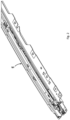
- FIG 1 part of a vehicle 1 is shown which in its stationary roof 2 is provided with an open roof construction 3.
- Part of the open roof construction is a panel 4 which can be moved between different positions (such as a closed position and the open position illustrated in figure 1 ) by means of a moving mechanism 5 (see figure 2 ).
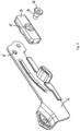
- the precise construction and operation of the moving mechanism 5 is not relevant for the present invention. It only is important that it firstly comprises at least a movable lever 6 ( figures 3-11 ).
- the movable lever 6 may be a front lever attached to a support 7 for the panel 4, but it is noted that the invention is not limited to such a specific type of lever.
- a pin-like member 8 (for example a pin or bolt) with a first end is connected to the lever 6 (for example inserted in a hole 6' of the lever) and with a second end is connected to a slide shoe 9 (for example partly housed in a recess 9' of the slide shoe), thus connecting the slide shoe 9 to the lever 6 (while generally allowing the slide shoe to rotate with respect to the lever).
- the slide shoe 9, for defining a movement of the movable lever 6, cooperates with and moves longitudinally along a guide 10.
- the guide 10 and slide shoe 9 are provided with at least one pair of cooperating guide part and slide shoe part, as will be explained in detail below while discussing the figures 5-11 .
- the pin-like member 8 at its second end is provided with an enlarged head 11 intended for engaging the slide shoe 9 at a side thereof facing away from the lever 6.
- the dimensions of the enlarged head 11 are such that, as seen in a direction from the enlarged head 11 towards the lever 6, at least part of said enlarged head overlaps at least one guide part.
- the guide 10 is provided with two guide parts 12,13 (for example wall parts) at opposite (here upper and lower) sides of the pin-like member 8 and positioned between the enlarged head 11 and the lever 6.
- the slide shoe 9 is provided with two corresponding slide shoe parts 14,15 (for example recesses) at opposite sides of the pin-like member cooperating with the guide parts 12,13, such as to define two opposite pairs 12,14 and 13,15 each of which comprises a guide part 12,13 and a slide shoe part 14,15 cooperating with each other.
- the embodiment according to figure 6 is similar to that according to figure 5 , but in this embodiment the enlarged head 11 has an asymmetrical design.
- the slide shoe 9 additionally is provided with a reinforcement member 16 extending (at least partially) between the enlarged head 11 and the two pairs 12,14 and 13,15 of cooperating guide part and slide shoe part.
- the reinforcement member 16 is at least partially, and preferably entirely, embedded in the slide shoe 9.
- FIG 9 an embodiment is illustrated which bears much resemblance with the previous embodiment but which now, additionally, is provided with a reinforcement member.
- a first part 16' of the reinforcement member extends between the enlarged head 11 and the first pair 12,14 of said opposite pairs of cooperating guide part and slide shoe part
- a second part 16" of the reinforcement member extends at the side of the second pair 13,15 of said opposite pairs of cooperating guide part and slide shoe part facing away from the lever 6 (in this figure at the right side of said pair 13,15).
- the reinforcement member only comprises the first part 16' or only comprises the second part 16".
- lever 6 is U-shaped in the region where the pin-like member 8 is attached thereto.
- figure 11 illustrates an embodiment in which, again, only the first pair 12,14 of said opposite pairs of cooperating guide part and slide shoe part is located between the enlarged head 11 and the lever 6 (at the side of the enlarged head 11 facing towards the lever 6), whereas the second pair 13,15 of said opposite pairs of cooperating guide part and slide shoe part is located at the side of the lever 6 facing away from the enlarged head 11 (thus, in this figure at the left of the lever 6).
- first and second pairs 12,14 and 13,15 could be exchanged (for example in figure 11 the (upper) first pair 12,14 could be positioned at the left of the lever 6, whereas the (lower) second pair 13,15 then would be positioned between the lever 6 and the enlarged head 11).
Landscapes
- Engineering & Computer Science (AREA)
- Mechanical Engineering (AREA)
- Vehicle Interior And Exterior Ornaments, Soundproofing, And Insulation (AREA)
- Fittings On The Vehicle Exterior For Carrying Loads, And Devices For Holding Or Mounting Articles (AREA)
- Automotive Seat Belt Assembly (AREA)
Description
- The invention relates to an open roof construction for a vehicle in accordance with the preamble of the main claim. Such an open roof construction is known from
US 2006/082193 A1 . - In such an open roof construction the slide shoe contributes to defining the movement of the lever, and thus to the movement of the panel (for example between closed and open positions thereof). To ensure a safe operation of the open roof construction in general, and a reliable positioning of the panel in its different positions specifically, a proper cooperation between the slide shoe and the guide should be assured at any moment. Especially it should be avoided that in case of a crash situation (for example with the panel in its open position) the forces generated (even at low speeds) cause the slide shoe to disengage (partly or fully) from the guide.
- In accordance with the above state of the art the pin-like member at its second end (where it is connected to the slide shoe) is provided with an enlarged head intended for engaging the slide shoe at a side thereof facing away from the lever, wherein the dimensions of the enlarged head are such that, as seen in a direction from the enlarged head towards the lever, at least part of said enlarged head overlaps at least one guide part.
- It appeared that as a result of said overlap between the enlarged head and at least one guide part a proper cooperation between the slide shoe and guide (as occurs at the interface between the cooperating guide part and slide shoe part) even can be assured under severe conditions, such as a crash situation (for example with the panel in its open position). The enlarged head may limit or prevent a deformation of the slide shoe.
- In the state of the art open roof construction the guide is provided with two guide parts at opposite sides of the pin-like member (commonly above and below the pin-like member when the slide shoe moves in a substantially horizontal direction, as will be the case in most open roof constructions of the type the present invention relates to), whereas the slide shoe (likewise) is provided with two slide shoe parts at opposite sides of the pin-like member, such as to define two opposite pairs of cooperating guide part and slide shoe part.
- In view of the above it is an object of the present invention to provide an open roof construction in which a proper cooperation between the slide shoe and guide is maintained through a very large range of operational circumstances.
- The open roof construction in accordance with the present invention is characterised as set forth in the main claim.
- The enlarged head of the pin-like member may overlap with only one guide part, but when the enlarged head has such a design that it overlaps both opposite guide parts, the favourable effect obtained can be maximised.
- In one embodiment the enlarged head has an asymmetrical design. This may result in a different amount of overlap with respect to different guide parts, or it may result from a specific design of the slide shoe (for example when the pin-like member does not have a central position in the slide shoe).
- In one embodiment comprising two of said pairs of cooperating guide part and slide shoe part, both opposite pairs of cooperating guide part and slide shoe part are located between the enlarged head and the lever. In such an embodiment the enlarged head in an overlapping manner will cooperate with both guide parts.
- In another embodiment comprising two of said pairs of cooperating guide part and slide shoe part, only a first one of said opposite pairs of cooperating guide part and slide shoe part is located between the enlarged head and the lever, at the side of the enlarged head facing towards the lever, whereas the second one of said opposite pairs of cooperating guide part and slide shoe part is located at the side of the enlarged head facing away from the lever. In such an embodiment the enlarged head in an overlapping manner will only cooperate with the guide part of the first pair.
- In yet another embodiment of the open roof construction which also comprises two of said pairs of cooperating guide part and slide shoe part, again only a first one of said opposite pairs of cooperating guide part and slide shoe part is located between the enlarged head and the lever, at the side of the enlarged head facing towards the lever, whereas the second one of said opposite pairs of cooperating guide part and slide shoe part now is located at the side of the lever facing away from the enlarged head.
- In one embodiment the slide shoe is provided with a reinforcement member extending at least partially between the enlarged head and a pair of cooperating guide part and slide shoe part. Such a reinforcement member, which at least partially, and preferably entirely, may be embedded in the slide shoe, adds to the resistance of the slide shoe against disengaging from the guide by increasing the stiffness of the slide shoe. The reinforcement member may reduce deformations of the slide shoe and further may improve a transmission of forces between the enlarged head and a guide part. Such a reinforcement member, for example, may comprise a plate or disc made of a rigid material, such as plastic or metal and may have a wide range of shapes and dimensions, depending on the features of the slide shoe.
- In an embodiment of the open roof construction which again comprises two of said pairs of cooperating guide part and slide shoe part, the reinforcement member may extend between the enlarged head and both opposite pairs of cooperating guide part and slide shoe part, also when only one of said pairs is located between the enlarged head and the lever. However, this does not preclude the possibility that the reinforcement member extends in another manner.
- For example, it is possible that the reinforcement member firstly extends between the enlarged head and the first one of said opposite pairs of cooperating guide part and slide shoe part and secondly extends at the side of the second one of said opposite pairs of cooperating guide part and slide shoe part facing away from the lever.
- The respective cooperating guide parts and slide shoe parts may comprise longitudinally extending guide walls and longitudinally extending slide shoe recesses, respectively.
- When the open roof construction comprises two of said pairs of cooperating guide part and slide shoe part, most commonly the first one of said opposite pairs of cooperating guide part and slide shoe part is positioned above the pin-like member, whereas the second one of said opposite pairs of cooperating guide part and slide shoe part is positioned below the pin-like member, especially when the slide shoe carries out a horizontal movement along the guide.
- In one embodiment the lever is U-shaped in the region where the pin-like member is attached thereto. This may provide constructional and/or functional advantages.
- Hereinafter the invention will be elucidated by means of the drawings, in which:
-
Figure 1 illustrates a general view of a vehicle provided with an open roof construction, comprising a panel which is shown in an open position; -
Figure 2 illustrates part of a moving mechanism for the panel; -
Figure 3 shows an exploded view of said part of the moving mechanism; -
Figure 4 shows a lever, slide shoe and pin-like member in a disassembled state, and -
Figures 5-11 show cross-sectional views of different embodiments of the open roof construction according to the present invention. - In
figure 1 part of avehicle 1 is shown which in itsstationary roof 2 is provided with anopen roof construction 3. Part of the open roof construction is apanel 4 which can be moved between different positions (such as a closed position and the open position illustrated infigure 1 ) by means of a moving mechanism 5 (seefigure 2 ). - The precise construction and operation of the
moving mechanism 5 is not relevant for the present invention. It only is important that it firstly comprises at least a movable lever 6 (figures 3-11 ). Themovable lever 6 may be a front lever attached to asupport 7 for thepanel 4, but it is noted that the invention is not limited to such a specific type of lever. - A pin-like member 8 (for example a pin or bolt) with a first end is connected to the lever 6 (for example inserted in a hole 6' of the lever) and with a second end is connected to a slide shoe 9 (for example partly housed in a recess 9' of the slide shoe), thus connecting the
slide shoe 9 to the lever 6 (while generally allowing the slide shoe to rotate with respect to the lever). Theslide shoe 9, for defining a movement of themovable lever 6, cooperates with and moves longitudinally along aguide 10. For this, theguide 10 andslide shoe 9 are provided with at least one pair of cooperating guide part and slide shoe part, as will be explained in detail below while discussing thefigures 5-11 . - As will appear below, the pin-
like member 8 at its second end is provided with an enlargedhead 11 intended for engaging theslide shoe 9 at a side thereof facing away from thelever 6. The dimensions of the enlargedhead 11 are such that, as seen in a direction from the enlargedhead 11 towards thelever 6, at least part of said enlarged head overlaps at least one guide part. - Referring to
figure 5 , an embodiment is illustrated in cross section in which theguide 10 is provided with twoguide parts 12,13 (for example wall parts) at opposite (here upper and lower) sides of the pin-like member 8 and positioned between the enlargedhead 11 and thelever 6. Theslide shoe 9 is provided with two correspondingslide shoe parts 14,15 (for example recesses) at opposite sides of the pin-like member cooperating with theguide parts opposite pairs guide part slide shoe part - In
figure 5 one can see that, as seen in the viewing direction according to arrow V, the enlargedhead 11 of the pin-like member 8 overlaps both theguide parts 12 and 13 (in this embodiment one also could say that the width of a gap defined between theopposite guide parts - The embodiment according to
figure 6 is similar to that according tofigure 5 , but in this embodiment the enlargedhead 11 has an asymmetrical design. - In
figure 7 again an embodiment is illustrated similar to that offigure 5 . Now, however, theslide shoe 9 additionally is provided with areinforcement member 16 extending (at least partially) between the enlargedhead 11 and the twopairs reinforcement member 16 is at least partially, and preferably entirely, embedded in theslide shoe 9. - In the embodiment illustrated in
figure 8 only afirst pair head 11 and the movable lever 6 (or, in other words, at the side of the enlargedhead 11 facing towards themovable lever 6, in this figure at the left from the enlarged head 11), whereas thesecond pair head 11 facing away from the lever 6 (in this figure at the right from the enlarged head 11). - Now referring to
figure 9 , an embodiment is illustrated which bears much resemblance with the previous embodiment but which now, additionally, is provided with a reinforcement member. As illustrated, a first part 16' of the reinforcement member extends between the enlargedhead 11 and thefirst pair second part 16" of the reinforcement member extends at the side of thesecond pair pair 13,15). - It should be noted that it also is possible that the reinforcement member only comprises the first part 16' or only comprises the
second part 16". - The embodiment illustrated in
figure 10 is quite similar to that illustrated infigure 5 , but in this embodiment thelever 6 is U-shaped in the region where the pin-like member 8 is attached thereto. - Finally,
figure 11 illustrates an embodiment in which, again, only thefirst pair head 11 and the lever 6 (at the side of the enlargedhead 11 facing towards the lever 6), whereas thesecond pair lever 6 facing away from the enlarged head 11 (thus, in this figure at the left of the lever 6). - Of course, the positions of the first and
second pairs figure 11 the (upper)first pair lever 6, whereas the (lower)second pair lever 6 and the enlarged head 11). - The invention is not limited to the embodiments described before which may be varied widely within the scope of the invention as defined by the appending claims.
Claims (13)
- Open roof construction for a vehicle (1), comprising a panel (4) and a moving mechanism (5) intended for moving the panel between different positions, wherein the moving mechanism comprises at least a movable lever (6) to which, by means of a pin-like member (8), a slide shoe (9) is connected that, for defining a movement of the movable lever, cooperates with and moves longitudinally along a guide (10), wherein the pin-like member (8) at a first end is connected to said lever (6) and at a second end is connected to said slide shoe (9) and wherein the guide (10) is provided with two guide parts (12,13) at opposite sides of the pin-like member (8), whereas the slide shoe (9) is provided with two slide shoe parts (14,15) at opposite sides of the pin-like member, such as to define two opposite pairs (12,14;13,15) of cooperating guide part and slide shoe part, and wherein the pin-like member (8) at its second end is provided with an enlarged head (11) intended for engaging the slide shoe (9) at a side thereof facing away from the lever (6), wherein the dimensions of the enlarged head are such that, as seen in a direction from the enlarged head towards the lever, at least part of said enlarged head overlaps at least one guide part (12,13), characterized in that at least one pair (12,14;13,15) of cooperating guide part and slide shoe part is located between the enlarged head (11) and the lever (6).
- Open roof construction according to claim 1, wherein the enlarged head (11) has such a design that it overlaps both opposite guide parts (12,13).
- Open roof construction according to claim 2, wherein the enlarged head (11) has an asymmetrical design.
- Open roof construction according to any of the claims 1-3, wherein both opposite pairs (12,14;13,15) of cooperating guide part and slide shoe part are located between the enlarged head (11) and the lever (6).
- Open roof construction according to any of the claims 1-3, wherein only a first one (12,14) of said opposite pairs (12,14;13,15) of cooperating guide part and slide shoe part is located between the enlarged head (11) and the lever (6), at the side of the enlarged head facing towards the lever, whereas the second one (13,15) of said opposite pairs of cooperating guide part and slide shoe part is located at the side of the enlarged head facing away from the lever.
- Open roof construction according to any of the claims 1-3, wherein only a first one (12,14) of said opposite pairs (12,14;13,15) of cooperating guide part and slide shoe part is located between the enlarged head (11) and the lever (6), at the side of the enlarged head facing towards the lever, whereas the second one (13,15) of said opposite pairs of cooperating guide part and slide shoe part is located at the side of the lever facing away from the enlarged head.
- Open roof construction according to any of the previous claims, wherein the slide shoe (9) is provided with a reinforcement member (16;16',16") extending at least partially between the enlarged head (11) and a pair of cooperating guide part and slide shoe part.
- Open roof construction according to claim 7, wherein the reinforcement member (16;16',16") is at least partially, and preferably entirely, embedded in the slide shoe (9).
- Open roof construction according to claim 7 or 8 in combination with claim 4, wherein the reinforcement member extends between the enlarged head and both opposite pairs of cooperating guide part and slide shoe part.
- Open roof construction according to claim 7 or 8 in combination with claim 5, wherein the reinforcement member (16',16") firstly extends between the enlarged head (11) and the first one (12,14) of said opposite pairs of cooperating guide part and slide shoe part and secondly extends at the side of the second one (13,15) of said opposite pairs of cooperating guide part and slide shoe part facing away from the lever (6).
- Open roof construction according to any of the previous claims, wherein the respective cooperating guide parts (12,13) and slide shoe parts (14,15) comprise longitudinally extending guide walls and longitudinally extending slide shoe recesses, respectively.
- Open roof construction according to claim 5 or 6, wherein the first one (12,14) of said opposite pairs of cooperating guide part and slide shoe part is positioned above the pin-like member (8), whereas the second one (13,15) of said opposite pairs of cooperating guide part and slide shoe part is positioned below the pin-like member.
- Open roof construction according to any of the previous claims, wherein the lever (6) is U-shaped in the region where the pin-like member (8) is attached thereto .
Priority Applications (3)
| Application Number | Priority Date | Filing Date | Title |
|---|---|---|---|
| EP20216345.7A EP4019306B1 (en) | 2020-12-22 | 2020-12-22 | Open roof construction for a vehicle |
| CN202111511245.7A CN114654980B (en) | 2020-12-22 | 2021-12-06 | Open roof structure for vehicles |
| US17/554,774 US11807088B2 (en) | 2020-12-22 | 2021-12-17 | Open roof construction for a vehicle |
Applications Claiming Priority (1)
| Application Number | Priority Date | Filing Date | Title |
|---|---|---|---|
| EP20216345.7A EP4019306B1 (en) | 2020-12-22 | 2020-12-22 | Open roof construction for a vehicle |
Publications (2)
| Publication Number | Publication Date |
|---|---|
| EP4019306A1 EP4019306A1 (en) | 2022-06-29 |
| EP4019306B1 true EP4019306B1 (en) | 2024-03-13 |
Family
ID=73856727
Family Applications (1)
| Application Number | Title | Priority Date | Filing Date |
|---|---|---|---|
| EP20216345.7A Active EP4019306B1 (en) | 2020-12-22 | 2020-12-22 | Open roof construction for a vehicle |
Country Status (3)
| Country | Link |
|---|---|
| US (1) | US11807088B2 (en) |
| EP (1) | EP4019306B1 (en) |
| CN (1) | CN114654980B (en) |
Families Citing this family (1)
| Publication number | Priority date | Publication date | Assignee | Title |
|---|---|---|---|---|
| DE102021114030B4 (en) * | 2021-05-31 | 2024-06-13 | Webasto SE | Fixed roof element for a vehicle roof, comprising a guide rail or other element of a shading system |
Family Cites Families (11)
| Publication number | Priority date | Publication date | Assignee | Title |
|---|---|---|---|---|
| DE2840443C2 (en) * | 1978-09-16 | 1982-08-12 | Webasto-Werk W. Baier GmbH & Co, 8035 Gauting | Device for adjusting the height of a rigid sliding cover |
| US5154482A (en) * | 1990-03-31 | 1992-10-13 | Aisin Seiki Kabushiki Kaisha | Outer sliding-type sunroof |
| JP3409368B2 (en) * | 1993-06-25 | 2003-05-26 | アイシン精機株式会社 | Sunroof device for vehicles |
| IT1261560B (en) * | 1993-08-11 | 1996-05-23 | DEVICE FOR OPENING AND CLOSING A CAR ROOF | |
| JP4367109B2 (en) * | 2003-11-27 | 2009-11-18 | アイシン精機株式会社 | Sunroof device |
| DE102004050609B3 (en) * | 2004-10-15 | 2006-03-16 | Dr.Ing.H.C. F. Porsche Ag | Roof arrangement for a vehicle |
| JP5671914B2 (en) * | 2010-09-29 | 2015-02-18 | アイシン精機株式会社 | Vehicle roof device |
| EP2711219B1 (en) * | 2012-09-25 | 2015-07-22 | Inalfa Roof Systems Group B.V. | Drive mechanism and open roof construction provided therewith |
| EP2727755B1 (en) * | 2012-10-30 | 2015-10-21 | Inalfa Roof Systems Group B.V. | Open roof construction for a vehicle |
| CN203681215U (en) * | 2013-11-29 | 2014-07-02 | 银娜珐天窗系统集团股份有限公司 | Guide rail, panel with guide rail, and car roof component |
| US9981539B1 (en) * | 2017-01-31 | 2018-05-29 | Inalfa Roof Systems Group, B.V. | Open roof construction for a vehicle |
-
2020
- 2020-12-22 EP EP20216345.7A patent/EP4019306B1/en active Active
-
2021
- 2021-12-06 CN CN202111511245.7A patent/CN114654980B/en active Active
- 2021-12-17 US US17/554,774 patent/US11807088B2/en active Active
Also Published As
| Publication number | Publication date |
|---|---|
| CN114654980B (en) | 2026-02-27 |
| EP4019306A1 (en) | 2022-06-29 |
| US20220194192A1 (en) | 2022-06-23 |
| US11807088B2 (en) | 2023-11-07 |
| CN114654980A (en) | 2022-06-24 |
Similar Documents
| Publication | Publication Date | Title |
|---|---|---|
| KR101342350B1 (en) | Door check link apparatus for vehicle | |
| EP3086995B1 (en) | Vehicle side portion structure with two parts reinforcing b-pillar member for improved side crash worthiness | |
| US7914073B2 (en) | Slider structure of sunroof apparatus | |
| EP2196354B1 (en) | Vehicle seat slide device | |
| EP2030872B1 (en) | Lower structure of vehicle body | |
| US12172501B2 (en) | Vehicle door assembly | |
| US4394792A (en) | Buckle for a safety belt | |
| JP2637704B2 (en) | Guide link for sliding cover attached to sliding / lifting roof structure for vehicles | |
| EP0098560B1 (en) | Lock arrangement for a vehicle sliding door | |
| EP4019306B1 (en) | Open roof construction for a vehicle | |
| EP0609029A1 (en) | Rear door assembly for automobiles | |
| US4393557A (en) | Safety belt buckle | |
| JP6483301B1 (en) | Slide device for automobile sunroof | |
| WO2009012840A1 (en) | Locking device for the bonnet of a motor vehicle | |
| US20210078391A1 (en) | Vehicle opening-closing structure | |
| CN103085684B (en) | Automobile, automobile seat and sliding rail mechanism of automobile seat | |
| CA1212031A (en) | Seat mount for a motor vehicle | |
| EP3564054B1 (en) | Locking mechanism and open roof construction provided therewith | |
| US11541732B1 (en) | Vehicle door assembly | |
| US12330484B2 (en) | Vehicle door system and a method for improving durability of a door system | |
| CN203046937U (en) | Automobile, automobile seat and sliding rail mechanism thereof | |
| US20230193664A1 (en) | Door latch jamming assembly | |
| EP4268988A1 (en) | Vehicle center pillar member and method for manufacturing same | |
| US20050001447A1 (en) | Actuating device for open/close member of vehicle | |
| CN202301895U (en) | Gear handle with built-in type gear unlocking button |
Legal Events
| Date | Code | Title | Description |
|---|---|---|---|
| PUAI | Public reference made under article 153(3) epc to a published international application that has entered the european phase |
Free format text: ORIGINAL CODE: 0009012 |
|
| STAA | Information on the status of an ep patent application or granted ep patent |
Free format text: STATUS: THE APPLICATION HAS BEEN PUBLISHED |
|
| AK | Designated contracting states |
Kind code of ref document: A1 Designated state(s): AL AT BE BG CH CY CZ DE DK EE ES FI FR GB GR HR HU IE IS IT LI LT LU LV MC MK MT NL NO PL PT RO RS SE SI SK SM TR |
|
| STAA | Information on the status of an ep patent application or granted ep patent |
Free format text: STATUS: REQUEST FOR EXAMINATION WAS MADE |
|
| 17P | Request for examination filed |
Effective date: 20221221 |
|
| RBV | Designated contracting states (corrected) |
Designated state(s): AL AT BE BG CH CY CZ DE DK EE ES FI FR GB GR HR HU IE IS IT LI LT LU LV MC MK MT NL NO PL PT RO RS SE SI SK SM TR |
|
| GRAP | Despatch of communication of intention to grant a patent |
Free format text: ORIGINAL CODE: EPIDOSNIGR1 |
|
| STAA | Information on the status of an ep patent application or granted ep patent |
Free format text: STATUS: GRANT OF PATENT IS INTENDED |
|
| INTG | Intention to grant announced |
Effective date: 20231026 |
|
| GRAS | Grant fee paid |
Free format text: ORIGINAL CODE: EPIDOSNIGR3 |
|
| GRAA | (expected) grant |
Free format text: ORIGINAL CODE: 0009210 |
|
| GRAF | Information related to payment of grant fee modified |
Free format text: ORIGINAL CODE: EPIDOSCIGR3 |
|
| STAA | Information on the status of an ep patent application or granted ep patent |
Free format text: STATUS: THE PATENT HAS BEEN GRANTED |
|
| AK | Designated contracting states |
Kind code of ref document: B1 Designated state(s): AL AT BE BG CH CY CZ DE DK EE ES FI FR GB GR HR HU IE IS IT LI LT LU LV MC MK MT NL NO PL PT RO RS SE SI SK SM TR |
|
| REG | Reference to a national code |
Ref country code: GB Ref legal event code: FG4D |
|
| REG | Reference to a national code |
Ref country code: CH Ref legal event code: EP |
|
| REG | Reference to a national code |
Ref country code: DE Ref legal event code: R096 Ref document number: 602020027116 Country of ref document: DE |
|
| REG | Reference to a national code |
Ref country code: IE Ref legal event code: FG4D |
|
| PG25 | Lapsed in a contracting state [announced via postgrant information from national office to epo] |
Ref country code: LT Free format text: LAPSE BECAUSE OF FAILURE TO SUBMIT A TRANSLATION OF THE DESCRIPTION OR TO PAY THE FEE WITHIN THE PRESCRIBED TIME-LIMIT Effective date: 20240313 |
|
| REG | Reference to a national code |
Ref country code: LT Ref legal event code: MG9D |
|
| PG25 | Lapsed in a contracting state [announced via postgrant information from national office to epo] |
Ref country code: GR Free format text: LAPSE BECAUSE OF FAILURE TO SUBMIT A TRANSLATION OF THE DESCRIPTION OR TO PAY THE FEE WITHIN THE PRESCRIBED TIME-LIMIT Effective date: 20240614 |
|
| REG | Reference to a national code |
Ref country code: NL Ref legal event code: MP Effective date: 20240313 |
|
| PG25 | Lapsed in a contracting state [announced via postgrant information from national office to epo] |
Ref country code: HR Free format text: LAPSE BECAUSE OF FAILURE TO SUBMIT A TRANSLATION OF THE DESCRIPTION OR TO PAY THE FEE WITHIN THE PRESCRIBED TIME-LIMIT Effective date: 20240313 Ref country code: RS Free format text: LAPSE BECAUSE OF FAILURE TO SUBMIT A TRANSLATION OF THE DESCRIPTION OR TO PAY THE FEE WITHIN THE PRESCRIBED TIME-LIMIT Effective date: 20240613 |
|
| PG25 | Lapsed in a contracting state [announced via postgrant information from national office to epo] |
Ref country code: ES Free format text: LAPSE BECAUSE OF FAILURE TO SUBMIT A TRANSLATION OF THE DESCRIPTION OR TO PAY THE FEE WITHIN THE PRESCRIBED TIME-LIMIT Effective date: 20240313 |
|
| PG25 | Lapsed in a contracting state [announced via postgrant information from national office to epo] |
Ref country code: RS Free format text: LAPSE BECAUSE OF FAILURE TO SUBMIT A TRANSLATION OF THE DESCRIPTION OR TO PAY THE FEE WITHIN THE PRESCRIBED TIME-LIMIT Effective date: 20240613 Ref country code: NO Free format text: LAPSE BECAUSE OF FAILURE TO SUBMIT A TRANSLATION OF THE DESCRIPTION OR TO PAY THE FEE WITHIN THE PRESCRIBED TIME-LIMIT Effective date: 20240613 Ref country code: LT Free format text: LAPSE BECAUSE OF FAILURE TO SUBMIT A TRANSLATION OF THE DESCRIPTION OR TO PAY THE FEE WITHIN THE PRESCRIBED TIME-LIMIT Effective date: 20240313 Ref country code: HR Free format text: LAPSE BECAUSE OF FAILURE TO SUBMIT A TRANSLATION OF THE DESCRIPTION OR TO PAY THE FEE WITHIN THE PRESCRIBED TIME-LIMIT Effective date: 20240313 Ref country code: GR Free format text: LAPSE BECAUSE OF FAILURE TO SUBMIT A TRANSLATION OF THE DESCRIPTION OR TO PAY THE FEE WITHIN THE PRESCRIBED TIME-LIMIT Effective date: 20240614 Ref country code: FI Free format text: LAPSE BECAUSE OF FAILURE TO SUBMIT A TRANSLATION OF THE DESCRIPTION OR TO PAY THE FEE WITHIN THE PRESCRIBED TIME-LIMIT Effective date: 20240313 Ref country code: ES Free format text: LAPSE BECAUSE OF FAILURE TO SUBMIT A TRANSLATION OF THE DESCRIPTION OR TO PAY THE FEE WITHIN THE PRESCRIBED TIME-LIMIT Effective date: 20240313 Ref country code: BG Free format text: LAPSE BECAUSE OF FAILURE TO SUBMIT A TRANSLATION OF THE DESCRIPTION OR TO PAY THE FEE WITHIN THE PRESCRIBED TIME-LIMIT Effective date: 20240313 |
|
| REG | Reference to a national code |
Ref country code: AT Ref legal event code: MK05 Ref document number: 1665436 Country of ref document: AT Kind code of ref document: T Effective date: 20240313 |
|
| PG25 | Lapsed in a contracting state [announced via postgrant information from national office to epo] |
Ref country code: SE Free format text: LAPSE BECAUSE OF FAILURE TO SUBMIT A TRANSLATION OF THE DESCRIPTION OR TO PAY THE FEE WITHIN THE PRESCRIBED TIME-LIMIT Effective date: 20240313 Ref country code: LV Free format text: LAPSE BECAUSE OF FAILURE TO SUBMIT A TRANSLATION OF THE DESCRIPTION OR TO PAY THE FEE WITHIN THE PRESCRIBED TIME-LIMIT Effective date: 20240313 |
|
| PG25 | Lapsed in a contracting state [announced via postgrant information from national office to epo] |
Ref country code: NL Free format text: LAPSE BECAUSE OF FAILURE TO SUBMIT A TRANSLATION OF THE DESCRIPTION OR TO PAY THE FEE WITHIN THE PRESCRIBED TIME-LIMIT Effective date: 20240313 |
|
| PG25 | Lapsed in a contracting state [announced via postgrant information from national office to epo] |
Ref country code: NL Free format text: LAPSE BECAUSE OF FAILURE TO SUBMIT A TRANSLATION OF THE DESCRIPTION OR TO PAY THE FEE WITHIN THE PRESCRIBED TIME-LIMIT Effective date: 20240313 |
|
| PG25 | Lapsed in a contracting state [announced via postgrant information from national office to epo] |
Ref country code: IS Free format text: LAPSE BECAUSE OF FAILURE TO SUBMIT A TRANSLATION OF THE DESCRIPTION OR TO PAY THE FEE WITHIN THE PRESCRIBED TIME-LIMIT Effective date: 20240713 |
|
| PG25 | Lapsed in a contracting state [announced via postgrant information from national office to epo] |
Ref country code: PT Free format text: LAPSE BECAUSE OF FAILURE TO SUBMIT A TRANSLATION OF THE DESCRIPTION OR TO PAY THE FEE WITHIN THE PRESCRIBED TIME-LIMIT Effective date: 20240715 Ref country code: SM Free format text: LAPSE BECAUSE OF FAILURE TO SUBMIT A TRANSLATION OF THE DESCRIPTION OR TO PAY THE FEE WITHIN THE PRESCRIBED TIME-LIMIT Effective date: 20240313 |
|
| PG25 | Lapsed in a contracting state [announced via postgrant information from national office to epo] |
Ref country code: EE Free format text: LAPSE BECAUSE OF FAILURE TO SUBMIT A TRANSLATION OF THE DESCRIPTION OR TO PAY THE FEE WITHIN THE PRESCRIBED TIME-LIMIT Effective date: 20240313 Ref country code: CZ Free format text: LAPSE BECAUSE OF FAILURE TO SUBMIT A TRANSLATION OF THE DESCRIPTION OR TO PAY THE FEE WITHIN THE PRESCRIBED TIME-LIMIT Effective date: 20240313 |
|
| PG25 | Lapsed in a contracting state [announced via postgrant information from national office to epo] |
Ref country code: AT Free format text: LAPSE BECAUSE OF FAILURE TO SUBMIT A TRANSLATION OF THE DESCRIPTION OR TO PAY THE FEE WITHIN THE PRESCRIBED TIME-LIMIT Effective date: 20240313 |
|
| PG25 | Lapsed in a contracting state [announced via postgrant information from national office to epo] |
Ref country code: PL Free format text: LAPSE BECAUSE OF FAILURE TO SUBMIT A TRANSLATION OF THE DESCRIPTION OR TO PAY THE FEE WITHIN THE PRESCRIBED TIME-LIMIT Effective date: 20240313 |
|
| PG25 | Lapsed in a contracting state [announced via postgrant information from national office to epo] |
Ref country code: SK Free format text: LAPSE BECAUSE OF FAILURE TO SUBMIT A TRANSLATION OF THE DESCRIPTION OR TO PAY THE FEE WITHIN THE PRESCRIBED TIME-LIMIT Effective date: 20240313 |
|
| PG25 | Lapsed in a contracting state [announced via postgrant information from national office to epo] |
Ref country code: SM Free format text: LAPSE BECAUSE OF FAILURE TO SUBMIT A TRANSLATION OF THE DESCRIPTION OR TO PAY THE FEE WITHIN THE PRESCRIBED TIME-LIMIT Effective date: 20240313 Ref country code: SK Free format text: LAPSE BECAUSE OF FAILURE TO SUBMIT A TRANSLATION OF THE DESCRIPTION OR TO PAY THE FEE WITHIN THE PRESCRIBED TIME-LIMIT Effective date: 20240313 Ref country code: RO Free format text: LAPSE BECAUSE OF FAILURE TO SUBMIT A TRANSLATION OF THE DESCRIPTION OR TO PAY THE FEE WITHIN THE PRESCRIBED TIME-LIMIT Effective date: 20240313 Ref country code: PT Free format text: LAPSE BECAUSE OF FAILURE TO SUBMIT A TRANSLATION OF THE DESCRIPTION OR TO PAY THE FEE WITHIN THE PRESCRIBED TIME-LIMIT Effective date: 20240715 Ref country code: PL Free format text: LAPSE BECAUSE OF FAILURE TO SUBMIT A TRANSLATION OF THE DESCRIPTION OR TO PAY THE FEE WITHIN THE PRESCRIBED TIME-LIMIT Effective date: 20240313 Ref country code: IS Free format text: LAPSE BECAUSE OF FAILURE TO SUBMIT A TRANSLATION OF THE DESCRIPTION OR TO PAY THE FEE WITHIN THE PRESCRIBED TIME-LIMIT Effective date: 20240713 Ref country code: EE Free format text: LAPSE BECAUSE OF FAILURE TO SUBMIT A TRANSLATION OF THE DESCRIPTION OR TO PAY THE FEE WITHIN THE PRESCRIBED TIME-LIMIT Effective date: 20240313 Ref country code: CZ Free format text: LAPSE BECAUSE OF FAILURE TO SUBMIT A TRANSLATION OF THE DESCRIPTION OR TO PAY THE FEE WITHIN THE PRESCRIBED TIME-LIMIT Effective date: 20240313 Ref country code: AT Free format text: LAPSE BECAUSE OF FAILURE TO SUBMIT A TRANSLATION OF THE DESCRIPTION OR TO PAY THE FEE WITHIN THE PRESCRIBED TIME-LIMIT Effective date: 20240313 |
|
| PG25 | Lapsed in a contracting state [announced via postgrant information from national office to epo] |
Ref country code: IT Free format text: LAPSE BECAUSE OF FAILURE TO SUBMIT A TRANSLATION OF THE DESCRIPTION OR TO PAY THE FEE WITHIN THE PRESCRIBED TIME-LIMIT Effective date: 20240313 |
|
| REG | Reference to a national code |
Ref country code: DE Ref legal event code: R097 Ref document number: 602020027116 Country of ref document: DE |
|
| PG25 | Lapsed in a contracting state [announced via postgrant information from national office to epo] |
Ref country code: IT Free format text: LAPSE BECAUSE OF FAILURE TO SUBMIT A TRANSLATION OF THE DESCRIPTION OR TO PAY THE FEE WITHIN THE PRESCRIBED TIME-LIMIT Effective date: 20240313 |
|
| PG25 | Lapsed in a contracting state [announced via postgrant information from national office to epo] |
Ref country code: DK Free format text: LAPSE BECAUSE OF FAILURE TO SUBMIT A TRANSLATION OF THE DESCRIPTION OR TO PAY THE FEE WITHIN THE PRESCRIBED TIME-LIMIT Effective date: 20240313 |
|
| PLBE | No opposition filed within time limit |
Free format text: ORIGINAL CODE: 0009261 |
|
| STAA | Information on the status of an ep patent application or granted ep patent |
Free format text: STATUS: NO OPPOSITION FILED WITHIN TIME LIMIT |
|
| PG25 | Lapsed in a contracting state [announced via postgrant information from national office to epo] |
Ref country code: DK Free format text: LAPSE BECAUSE OF FAILURE TO SUBMIT A TRANSLATION OF THE DESCRIPTION OR TO PAY THE FEE WITHIN THE PRESCRIBED TIME-LIMIT Effective date: 20240313 |
|
| 26N | No opposition filed |
Effective date: 20241216 |
|
| PG25 | Lapsed in a contracting state [announced via postgrant information from national office to epo] |
Ref country code: SI Free format text: LAPSE BECAUSE OF FAILURE TO SUBMIT A TRANSLATION OF THE DESCRIPTION OR TO PAY THE FEE WITHIN THE PRESCRIBED TIME-LIMIT Effective date: 20240313 |
|
| PG25 | Lapsed in a contracting state [announced via postgrant information from national office to epo] |
Ref country code: MC Free format text: LAPSE BECAUSE OF FAILURE TO SUBMIT A TRANSLATION OF THE DESCRIPTION OR TO PAY THE FEE WITHIN THE PRESCRIBED TIME-LIMIT Effective date: 20240313 |
|
| REG | Reference to a national code |
Ref country code: CH Ref legal event code: PL |
|
| PG25 | Lapsed in a contracting state [announced via postgrant information from national office to epo] |
Ref country code: LU Free format text: LAPSE BECAUSE OF NON-PAYMENT OF DUE FEES Effective date: 20241222 |
|
| GBPC | Gb: european patent ceased through non-payment of renewal fee |
Effective date: 20241222 |
|
| REG | Reference to a national code |
Ref country code: BE Ref legal event code: MM Effective date: 20241231 |
|
| PG25 | Lapsed in a contracting state [announced via postgrant information from national office to epo] |
Ref country code: BE Free format text: LAPSE BECAUSE OF NON-PAYMENT OF DUE FEES Effective date: 20241231 Ref country code: GB Free format text: LAPSE BECAUSE OF NON-PAYMENT OF DUE FEES Effective date: 20241222 |
|
| PG25 | Lapsed in a contracting state [announced via postgrant information from national office to epo] |
Ref country code: CH Free format text: LAPSE BECAUSE OF NON-PAYMENT OF DUE FEES Effective date: 20241231 |
|
| PG25 | Lapsed in a contracting state [announced via postgrant information from national office to epo] |
Ref country code: IE Free format text: LAPSE BECAUSE OF NON-PAYMENT OF DUE FEES Effective date: 20241222 |
|
| PGFP | Annual fee paid to national office [announced via postgrant information from national office to epo] |
Ref country code: FR Payment date: 20251230 Year of fee payment: 6 |
|
| PGFP | Annual fee paid to national office [announced via postgrant information from national office to epo] |
Ref country code: DE Payment date: 20251229 Year of fee payment: 6 |