EP4019241A2 - Rfid tag assembly for securing to a tire - Google Patents
Rfid tag assembly for securing to a tire Download PDFInfo
- Publication number
- EP4019241A2 EP4019241A2 EP21208626.8A EP21208626A EP4019241A2 EP 4019241 A2 EP4019241 A2 EP 4019241A2 EP 21208626 A EP21208626 A EP 21208626A EP 4019241 A2 EP4019241 A2 EP 4019241A2
- Authority
- EP
- European Patent Office
- Prior art keywords
- polyester layer
- rfid tag
- tag assembly
- tire
- radially inner
- Prior art date
- Legal status (The legal status is an assumption and is not a legal conclusion. Google has not performed a legal analysis and makes no representation as to the accuracy of the status listed.)
- Granted
Links
Images

Classifications
-
- B—PERFORMING OPERATIONS; TRANSPORTING
- B60—VEHICLES IN GENERAL
- B60C—VEHICLE TYRES; TYRE INFLATION; TYRE CHANGING; CONNECTING VALVES TO INFLATABLE ELASTIC BODIES IN GENERAL; DEVICES OR ARRANGEMENTS RELATED TO TYRES
- B60C19/00—Tyre parts or constructions not otherwise provided for
-
- G—PHYSICS
- G06—COMPUTING OR CALCULATING; COUNTING
- G06K—GRAPHICAL DATA READING; PRESENTATION OF DATA; RECORD CARRIERS; HANDLING RECORD CARRIERS
- G06K19/00—Record carriers for use with machines and with at least a part designed to carry digital markings
- G06K19/06—Record carriers for use with machines and with at least a part designed to carry digital markings characterised by the kind of the digital marking, e.g. shape, nature, code
- G06K19/067—Record carriers with conductive marks, printed circuits or semiconductor circuit elements, e.g. credit or identity cards also with resonating or responding marks without active components
- G06K19/07—Record carriers with conductive marks, printed circuits or semiconductor circuit elements, e.g. credit or identity cards also with resonating or responding marks without active components with integrated circuit chips
- G06K19/077—Constructional details, e.g. mounting of circuits in the carrier
- G06K19/0772—Physical layout of the record carrier
- G06K19/07722—Physical layout of the record carrier the record carrier being multilayered, e.g. laminated sheets
-
- B—PERFORMING OPERATIONS; TRANSPORTING
- B29—WORKING OF PLASTICS; WORKING OF SUBSTANCES IN A PLASTIC STATE IN GENERAL
- B29D—PRODUCING PARTICULAR ARTICLES FROM PLASTICS OR FROM SUBSTANCES IN A PLASTIC STATE
- B29D30/00—Producing pneumatic or solid tyres or parts thereof
- B29D30/0061—Accessories, details or auxiliary operations not otherwise provided for
-
- B—PERFORMING OPERATIONS; TRANSPORTING
- B32—LAYERED PRODUCTS
- B32B—LAYERED PRODUCTS, i.e. PRODUCTS BUILT-UP OF STRATA OF FLAT OR NON-FLAT, e.g. CELLULAR OR HONEYCOMB, FORM
- B32B27/00—Layered products comprising a layer of synthetic resin
- B32B27/06—Layered products comprising a layer of synthetic resin as the main or only constituent of a layer, which is next to another layer of the same or of a different material
- B32B27/08—Layered products comprising a layer of synthetic resin as the main or only constituent of a layer, which is next to another layer of the same or of a different material of synthetic resin
-
- B—PERFORMING OPERATIONS; TRANSPORTING
- B32—LAYERED PRODUCTS
- B32B—LAYERED PRODUCTS, i.e. PRODUCTS BUILT-UP OF STRATA OF FLAT OR NON-FLAT, e.g. CELLULAR OR HONEYCOMB, FORM
- B32B27/00—Layered products comprising a layer of synthetic resin
- B32B27/32—Layered products comprising a layer of synthetic resin comprising polyolefins
-
- B—PERFORMING OPERATIONS; TRANSPORTING
- B32—LAYERED PRODUCTS
- B32B—LAYERED PRODUCTS, i.e. PRODUCTS BUILT-UP OF STRATA OF FLAT OR NON-FLAT, e.g. CELLULAR OR HONEYCOMB, FORM
- B32B27/00—Layered products comprising a layer of synthetic resin
- B32B27/34—Layered products comprising a layer of synthetic resin comprising polyamides
-
- B—PERFORMING OPERATIONS; TRANSPORTING
- B32—LAYERED PRODUCTS
- B32B—LAYERED PRODUCTS, i.e. PRODUCTS BUILT-UP OF STRATA OF FLAT OR NON-FLAT, e.g. CELLULAR OR HONEYCOMB, FORM
- B32B27/00—Layered products comprising a layer of synthetic resin
- B32B27/36—Layered products comprising a layer of synthetic resin comprising polyesters
-
- B—PERFORMING OPERATIONS; TRANSPORTING
- B32—LAYERED PRODUCTS
- B32B—LAYERED PRODUCTS, i.e. PRODUCTS BUILT-UP OF STRATA OF FLAT OR NON-FLAT, e.g. CELLULAR OR HONEYCOMB, FORM
- B32B3/00—Layered products comprising a layer with external or internal discontinuities or unevennesses, or a layer of non-planar shape; Layered products comprising a layer having particular features of form
- B32B3/02—Layered products comprising a layer with external or internal discontinuities or unevennesses, or a layer of non-planar shape; Layered products comprising a layer having particular features of form characterised by features of form at particular places, e.g. in edge regions
- B32B3/08—Layered products comprising a layer with external or internal discontinuities or unevennesses, or a layer of non-planar shape; Layered products comprising a layer having particular features of form characterised by features of form at particular places, e.g. in edge regions characterised by added members at particular parts
-
- B—PERFORMING OPERATIONS; TRANSPORTING
- B60—VEHICLES IN GENERAL
- B60C—VEHICLE TYRES; TYRE INFLATION; TYRE CHANGING; CONNECTING VALVES TO INFLATABLE ELASTIC BODIES IN GENERAL; DEVICES OR ARRANGEMENTS RELATED TO TYRES
- B60C5/00—Inflatable pneumatic tyres or inner tubes
- B60C5/12—Inflatable pneumatic tyres or inner tubes without separate inflatable inserts, e.g. tubeless tyres with transverse section open to the rim
- B60C5/14—Inflatable pneumatic tyres or inner tubes without separate inflatable inserts, e.g. tubeless tyres with transverse section open to the rim with impervious liner or coating on the inner wall of the tyre
-
- G—PHYSICS
- G06—COMPUTING OR CALCULATING; COUNTING
- G06K—GRAPHICAL DATA READING; PRESENTATION OF DATA; RECORD CARRIERS; HANDLING RECORD CARRIERS
- G06K19/00—Record carriers for use with machines and with at least a part designed to carry digital markings
- G06K19/06—Record carriers for use with machines and with at least a part designed to carry digital markings characterised by the kind of the digital marking, e.g. shape, nature, code
- G06K19/067—Record carriers with conductive marks, printed circuits or semiconductor circuit elements, e.g. credit or identity cards also with resonating or responding marks without active components
- G06K19/07—Record carriers with conductive marks, printed circuits or semiconductor circuit elements, e.g. credit or identity cards also with resonating or responding marks without active components with integrated circuit chips
- G06K19/077—Constructional details, e.g. mounting of circuits in the carrier
- G06K19/07749—Constructional details, e.g. mounting of circuits in the carrier the record carrier being capable of non-contact communication, e.g. constructional details of the antenna of a non-contact smart card
-
- B—PERFORMING OPERATIONS; TRANSPORTING
- B29—WORKING OF PLASTICS; WORKING OF SUBSTANCES IN A PLASTIC STATE IN GENERAL
- B29D—PRODUCING PARTICULAR ARTICLES FROM PLASTICS OR FROM SUBSTANCES IN A PLASTIC STATE
- B29D30/00—Producing pneumatic or solid tyres or parts thereof
- B29D30/0061—Accessories, details or auxiliary operations not otherwise provided for
- B29D2030/0077—Directly attaching monitoring devices to tyres before or after vulcanization, e.g. microchips
-
- B—PERFORMING OPERATIONS; TRANSPORTING
- B32—LAYERED PRODUCTS
- B32B—LAYERED PRODUCTS, i.e. PRODUCTS BUILT-UP OF STRATA OF FLAT OR NON-FLAT, e.g. CELLULAR OR HONEYCOMB, FORM
- B32B2250/00—Layers arrangement
- B32B2250/24—All layers being polymeric
-
- B—PERFORMING OPERATIONS; TRANSPORTING
- B32—LAYERED PRODUCTS
- B32B—LAYERED PRODUCTS, i.e. PRODUCTS BUILT-UP OF STRATA OF FLAT OR NON-FLAT, e.g. CELLULAR OR HONEYCOMB, FORM
- B32B2307/00—Properties of the layers or laminate
- B32B2307/50—Properties of the layers or laminate having particular mechanical properties
- B32B2307/51—Elastic
-
- B—PERFORMING OPERATIONS; TRANSPORTING
- B32—LAYERED PRODUCTS
- B32B—LAYERED PRODUCTS, i.e. PRODUCTS BUILT-UP OF STRATA OF FLAT OR NON-FLAT, e.g. CELLULAR OR HONEYCOMB, FORM
- B32B2307/00—Properties of the layers or laminate
- B32B2307/50—Properties of the layers or laminate having particular mechanical properties
- B32B2307/542—Shear strength
-
- B—PERFORMING OPERATIONS; TRANSPORTING
- B32—LAYERED PRODUCTS
- B32B—LAYERED PRODUCTS, i.e. PRODUCTS BUILT-UP OF STRATA OF FLAT OR NON-FLAT, e.g. CELLULAR OR HONEYCOMB, FORM
- B32B2519/00—Labels, badges
- B32B2519/02—RFID tags
-
- B—PERFORMING OPERATIONS; TRANSPORTING
- B32—LAYERED PRODUCTS
- B32B—LAYERED PRODUCTS, i.e. PRODUCTS BUILT-UP OF STRATA OF FLAT OR NON-FLAT, e.g. CELLULAR OR HONEYCOMB, FORM
- B32B2605/00—Vehicles
-
- B—PERFORMING OPERATIONS; TRANSPORTING
- B32—LAYERED PRODUCTS
- B32B—LAYERED PRODUCTS, i.e. PRODUCTS BUILT-UP OF STRATA OF FLAT OR NON-FLAT, e.g. CELLULAR OR HONEYCOMB, FORM
- B32B7/00—Layered products characterised by the relation between layers; Layered products characterised by the relative orientation of features between layers, or by the relative values of a measurable parameter between layers, i.e. products comprising layers having different physical, chemical or physicochemical properties; Layered products characterised by the interconnection of layers
- B32B7/04—Interconnection of layers
- B32B7/12—Interconnection of layers using interposed adhesives or interposed materials with bonding properties
-
- B—PERFORMING OPERATIONS; TRANSPORTING
- B60—VEHICLES IN GENERAL
- B60C—VEHICLE TYRES; TYRE INFLATION; TYRE CHANGING; CONNECTING VALVES TO INFLATABLE ELASTIC BODIES IN GENERAL; DEVICES OR ARRANGEMENTS RELATED TO TYRES
- B60C19/00—Tyre parts or constructions not otherwise provided for
- B60C2019/004—Tyre sensors other than for detecting tyre pressure
Definitions
- the present invention relates to a RFID tag assembly for curing to rubber-based articles (e.g., cured tires, green tires, etc.) and, more particularly, to a RFID tag assembly attached to an internal surface (e.g., innerliner, ply, etc.) of a tire.
- rubber-based articles e.g., cured tires, green tires, etc.
- RFID tag assembly attached to an internal surface (e.g., innerliner, ply, etc.) of a tire.
- Articles of manufacture may commonly be monitored during manufacture and thereafter for inventory control purposes.
- One conventional practice may be to apply an RFID tag label to an article containing an identifier and/or other information associated with the article of manufacture.
- identifying tires and other rubber-based articles may be problematic, particularly if the identification is to occur prior to fabrication and/or prior to completion of production.
- Tires and a wide array of other rubber-based articles may be subjected to one or more vulcanization processes in which the tire and/or tire components may be fused, molded, and/or cured together.
- Vulcanization typically modifies an uncured rubber-based composition by forming an extensive network of molecular crosslinks within the rubber matrix, thereby significantly increasing the strength and durability of the rubber-based article.
- vulcanization techniques may include the application of elevated pressures and elevated temperatures to the "green" (e.g., uncured, non-vulcanized, non-cross-linked, etc.) rubber-based articles.
- adhesive-based RFID tags have been developed that may be applied to green rubber-based articles such as tires, and which may endure the relatively high temperatures and pressures associated with vulcanization. While generally satisfactory in many respects, adhesive RFID tags may not endure the lifetime of the article and may detach from the article due to the various types of stresses on the article both during and after production.
- Potential detachment of an RFID tag may be caused by tag stiffness and the inability to handle the relative flexibility of rubber during multiple stages of the tire-build process and when the tire is fitted on a rim. This detachment may initially begin during the vulcanization process while the mold is moving and continue right after curing when the tire temperature still elevated.
- the RFID tag may fall off immediately or, at the least, the adhesion may be weakened as a result of the movement. Additionally, during the process of fitting the tire on a rim, the tire (particularly the bead area) may be subjected to significant mechanical stress by the fitting machines. When tires are in use, the various road and driving stresses may cause the RFID tag to detach from the tire.
- RFID tag suppliers may concentrate on the development of better adhesives.
- tire and rubber product producers may experiment with positioning of the RFID tag by applying the RFID tag in the so-called "non-flexing-zones" of the tire or rubber product. While these activities may reduce detachment to some degree, these activities may not be ultimate solutions. Additionally, the addition of RFID chips to current solutions may contribute to detachment, and locating current RFID tags behind the metal rim post-fitting may impede the ability to read the RFID chip from a useful distance.
- an adhesive-based RFID tag capable of remaining attached and operable to a rubber-based article during article production (e.g., vulcanization), distribution, inventory, and article lifetime may be useful.
- the invention relates to a RFID tag assembly in accordance with claim 1 and to a tire in accordance with claim 12.
- An RFID tag assembly for attaching to a tire in accordance with a preferred aspect of the present invention consists of a first polyester layer, a second polyester layer adjacent the first polyester layer, the second polyester layer having an etched antenna and an RFID chip, and a third polyester layer adjacent the second polyester layer.
- the third polyester layer surrounds part of the first and second layers and is secured by heat to an innerliner of the tire.
- the second polyester layer includes a radially outermost topcoat sublayer.
- the second polyester layer includes a radially inner first polyester sublayer with a thermal printed barcode image.
- the second polyester layer is corona tested on both sides.
- the second polyester layer includes a radially inner first high temperature adhesive sublayer.
- the second polyester layer includes a radially inner polyamide sublayer with an etched antenna and an integrated circuit.
- the second polyester layer includes a radially inner second high temperature adhesive sublayer.
- the second polyester layer includes a radially inner first adhesion promoter sublayer.
- the second polyester layer includes a radially inner second polyester sublayer.
- the second polyester layer includes a radially inner second adhesion promoter sublayer.
- the second polyester layer includes a radially inner uncured rubber-based third adhesive sublayer.
- the second polyester layer includes an ultra-high molecular weight polyethylene (UHMWPE).
- UHMWPE ultra-high molecular weight polyethylene
- a tire in accordance with a preferred aspect of the present invention includes such an RFID tag assembly.
- RFID tags may enable various tire tracking solutions for articles of manufacture that include electronic identification provisions such as, for example, RFID devices incorporated in/onto a substrate such as a mesh backing/material such that the tags may be configured to withstand pressures, temperatures, and/or stresses associated with manufacturing (e.g., tire vulcanization) and a wide variety of uses of tires and other rubber products while concurrently maintaining operability during these processes, after these processes, and throughout the lifetime of the article thereby sensing and providing unique identifier(s) and/or other information about the article during distribution, inventory, and article life.
- the RFID tag may be affixed to, and/or incorporated on, a sidewall, a bead, and/or an innerliner of a wide array of tires.
- the thickness, surface area, and/or configuration of the different RFID tag materials may vary.
- tires may typically be used in combination with rims of a vehicle.
- the rubber-based tire may support, and provide grip for, the vehicle with a road or ground surface.
- the RFID tag may be used with bias tires, belted bias tires, radial tires, solid tires, semi-pneumatic tires, pneumatic tires, airless tires, non-pneumatic tires, truck/bus tires, airplane tires, agriculture tires, racing tires, etc.
- An RFID tag may withstand conditions typically associated with vulcanization processes without degradation.
- the term vulcanization as used herein may generally refer to heating to a temperature greater than 90°C, and up to 200 °C, for a predetermined time period, for example, from at least 10 minutes to as much as several hours.
- the RFID tag generally may include at least one RFID device.
- the RFID device generally includes an antenna for wirelessly transmitting and/or receiving RF signals and analog and/or digital electronics operatively connected thereto.
- the RFID device may include passive RFID devices and/or active and/or semi-passive RFID devices including a battery and/or other power source.
- the electronics may be implemented via an integrated circuit (IC) and/or microchip and/or other suitable electronic circuit, such as, for example, communications electronics, data memory, control logic, etc.
- the RFID device may operate in a variety of frequency ranges including, but not limited to, a low frequency (LF) range (e.g., from approximately 30 kHz to approximately 300 kHz), a high frequency (HF) and NFC (Near Field Communication) range (e.g., from approximately 3 MHz to approximately 30 MHz) and an ultra-high frequency (UHF) range (e.g., from approximately 300 MHz to approximately 3 GHz).
- LF low frequency
- HF high frequency
- NFC Near Field Communication
- UHF Ultra-high frequency
- a passive device may operate in any one of the aforementioned frequency ranges.
- LF systems may operate at about 124 kHz, 125 kHz, or 135 kHz
- HF and NFC systems may operate at about 13.56 MHz
- UHF systems may use a band from 860 MHz to 960 MHz.
- passive devices may use 2.45 GHz and/or other areas of the radio spectrum.
- Active RFID devices may operate at about 455 MHz, 2.45 GHz, or 5.8 GHz.
- Semi-passive RFID devices may operate at a frequency of about 2.4 GHz.
- the read range of an RFID device may be determined by the type of device (e.g., active, passive, semipassive, etc.).
- Passive LF RFID devices also referred to as LFID or LowFID devices
- passive HF RFID devices also referred to as HFID or HighFID or NFC devices
- passive UHF RFID devices also referred to as UHFID devices
- UHFID devices may typically be read from approximately 10 feet (3.05 meters) or more.
- passive RFID devices One factor influencing the read range for passive RFID devices is the method used to transmit data from the device to the reader (e.g., the coupling mode between the device and the reader--which may be inductive coupling or radiative/propagation coupling).
- the coupling mode between the device and the reader-- which may be inductive coupling or radiative/propagation coupling.
- Passive LFID devices and passive HFTD devices may use inductive coupling between the device and the reader, whereas passive UHFID devices may use radiative or propagation coupling between the device and the reader.
- the reader may emit electromagnetic energy that can illuminate the device.
- the device may gather the energy from the reader via an antenna, and the device's integrated circuit (IC) or microchip may use the gathered energy to change the load on the device antenna and reflect back an altered signal (e.g., backscatter).
- IC integrated circuit
- UHFID devices may communicate data in a variety of different ways such as increasing the amplitude of a reflected wave sent back to the reader (amplitude shift keying), shifting the reflected wave out of the phase of the received wave (phase shift keying), and/or changing the frequency of the reflected wave (frequency shift keying).
- the reader may then pick up the backscattered signal and convert the altered wave into data understood by the reader and/or an adjunct computer.
- the antenna employed in the RFID device may be affected by numerous factors, such as intended application, type of device (e.g., active, passive, semi-active, etc.), desired read range, device-to-reader coupling mode, and/or frequency of operation of the device.
- type of device e.g., active, passive, semi-active, etc.
- desired read range e.g., desired read range
- device-to-reader coupling mode e.g., a radio frequency of operation of the device.
- passive LFID devices may normally be inductively coupled with the reader, and because the voltage induced in the device antenna may be proportional to the operating frequency of the device, passive LFID devices may include a coil antenna with many turns in order to produce enough voltage to operate the device IC and/or microchip.
- a conventional HFID passive device may include a planar spiral antenna (e.g., with 5 to 7 turns over a credit-card-sized form factor) to provide read ranges on the order of tens of centimeters.
- HFID antenna coils may be less costly to produce (e.g., compared to LFID antenna coils) since they may be made using techniques relatively less expensive than wire winding (e.g., lithography or the like).
- UHFID passive devices may be radiatively and/or propagationally coupled with the reader antenna and consequently may employ conventional dipole-like antennas.
- the RFID tag used with the present invention may utilize any of the aforementioned RFID devices, as well as others not specifically mentioned.
- RFID tags may be advantageously attached to an innerliner of 11 a tire.
- the RFID tags may be received from suppliers on a roll with the RFID tags attached to a release liner with an uncured gum glue.
- the gum glue may have a good initial tack, or stickiness, to uncured rubber. However, after a curing/heating, the RFID tags may lose that initial tack and fall off the innerliner 11.
- a conventional roll 100 of example RFID tags 110 may include a radially outermost topcoat layer 111, a next radially inner first polyester layer 112 with a thermal printed barcode image (corona tested both sides), a next radially inner first high temperature adhesive layer 113, a next radially inner polyamide layer 114 with an etched antenna and IC, a next radially inner second high temperature adhesive layer 115, a next radially inner first adhesion promoter layer 116, a next radially inner second polyester layer 117, a next radially inner second adhesion promoter layer 118, a next radially inner uncured rubber-based third adhesive layer 119, and a removable liner 101 of the roll 100 for maintaining the RFID tags 110 prior to application to the innerliner 11, for example.
- a RFID tag of a system 200 in accordance with the present invention includes only three layers: a first inward facing polyester layer 211, a next outer second polyester layer 212 with an etched antenna and an RFID chip, and an outermost third polyester layer 213.
- the three layers 211, 212, 213 may be secured to each other by suitable glues and/or adhesion promoters.
- the first and second layers 211, 212 provide structural integrity to the RFID tag, but provide no adhesion to an innerliner 11.
- the liner is the third layer 213 itself and is sized to appropriately surround the first and second layers 211, 212 and be temporarily secured to the innerliner 11 before curing of the tire 10.
- the liner 213 preferably at least partially liquifies and permanently adheres to the innerliner 11 during cool down.
- Such a liner or third player 213 may be constructed of any suitable polymeric material such an ultra-high molecular weight polyethylene (UHMWPE).
- UHMWPE ultra-high molecular weight polyethylene
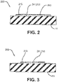
- the outermost third polyester layer or liner 213 is sealed to the innerliner 11 completely around the first and second layers 211, 212 ( FIG. 3 ).
- the outermost third polyester layer or liner 213 is sealed to the innerliner 11 only on top of the first and second layers 211, 212 ( FIG. 2 ).
- the outermost third polyester layer or liner 213 is sealed to the innerliner 11 around the first and second layers 211, 212 ( FIG. 2 ) but left with an opening 215 ( FIG. 2 ) forming a pocket for appropriate replacement/removal of the first and second layers 211, 212.
- the opening 215 is preferably on one lateral side of the first and second layers 211, 212 while the other lateral side is closed.
Landscapes
- Engineering & Computer Science (AREA)
- Mechanical Engineering (AREA)
- Computer Hardware Design (AREA)
- Microelectronics & Electronic Packaging (AREA)
- Physics & Mathematics (AREA)
- General Physics & Mathematics (AREA)
- Theoretical Computer Science (AREA)
- Tires In General (AREA)
- Tyre Moulding (AREA)
Abstract
Description
- The present invention relates to a RFID tag assembly for curing to rubber-based articles (e.g., cured tires, green tires, etc.) and, more particularly, to a RFID tag assembly attached to an internal surface (e.g., innerliner, ply, etc.) of a tire.
- Articles of manufacture may commonly be monitored during manufacture and thereafter for inventory control purposes. One conventional practice may be to apply an RFID tag label to an article containing an identifier and/or other information associated with the article of manufacture.
- Regarding tire manufacturing, to which the present invention may find particular application, identifying tires and other rubber-based articles may be problematic, particularly if the identification is to occur prior to fabrication and/or prior to completion of production. Tires and a wide array of other rubber-based articles may be subjected to one or more vulcanization processes in which the tire and/or tire components may be fused, molded, and/or cured together. Vulcanization typically modifies an uncured rubber-based composition by forming an extensive network of molecular crosslinks within the rubber matrix, thereby significantly increasing the strength and durability of the rubber-based article. Although numerous vulcanization techniques are known having various different curing methods, all, or nearly all, vulcanization techniques may include the application of elevated pressures and elevated temperatures to the "green" (e.g., uncured, non-vulcanized, non-cross-linked, etc.) rubber-based articles.
- In view of these process conditions, adhesive-based RFID tags have been developed that may be applied to green rubber-based articles such as tires, and which may endure the relatively high temperatures and pressures associated with vulcanization. While generally satisfactory in many respects, adhesive RFID tags may not endure the lifetime of the article and may detach from the article due to the various types of stresses on the article both during and after production.
- Potential detachment of an RFID tag may be caused by tag stiffness and the inability to handle the relative flexibility of rubber during multiple stages of the tire-build process and when the tire is fitted on a rim. This detachment may initially begin during the vulcanization process while the mold is moving and continue right after curing when the tire temperature still elevated.
- If the tire is released from the mold and moves (e.g., flexes), the RFID tag may fall off immediately or, at the least, the adhesion may be weakened as a result of the movement. Additionally, during the process of fitting the tire on a rim, the tire (particularly the bead area) may be subjected to significant mechanical stress by the fitting machines. When tires are in use, the various road and driving stresses may cause the RFID tag to detach from the tire.
- Within the tire industry, RFID tag suppliers may concentrate on the development of better adhesives. Conversely, tire and rubber product producers may experiment with positioning of the RFID tag by applying the RFID tag in the so-called "non-flexing-zones" of the tire or rubber product. While these activities may reduce detachment to some degree, these activities may not be ultimate solutions. Additionally, the addition of RFID chips to current solutions may contribute to detachment, and locating current RFID tags behind the metal rim post-fitting may impede the ability to read the RFID chip from a useful distance. Accordingly, an alternative to an adhesive-based RFID tag capable of remaining attached and operable to a rubber-based article during article production (e.g., vulcanization), distribution, inventory, and article lifetime may be useful.
- The invention relates to a RFID tag assembly in accordance with claim 1 and to a tire in accordance with
claim 12. - Dependent claims refer to preferred embodiment of the invention.
- An RFID tag assembly for attaching to a tire in accordance with a preferred aspect of the present invention consists of a first polyester layer, a second polyester layer adjacent the first polyester layer, the second polyester layer having an etched antenna and an RFID chip, and a third polyester layer adjacent the second polyester layer. The third polyester layer surrounds part of the first and second layers and is secured by heat to an innerliner of the tire.
- According to a preferred aspect of the RFID tag assembly, the second polyester layer includes a radially outermost topcoat sublayer.
- According to a preferred aspect of the RFID tag assembly, the second polyester layer includes a radially inner first polyester sublayer with a thermal printed barcode image.
- According to a preferred aspect of the RFID tag assembly, the second polyester layer is corona tested on both sides.
- According to a preferred aspect of the RFID tag assembly, the second polyester layer includes a radially inner first high temperature adhesive sublayer.
- According to a preferred aspect of the RFID tag assembly, the second polyester layer includes a radially inner polyamide sublayer with an etched antenna and an integrated circuit.
- According to a preferred aspect of the RFID tag assembly, the second polyester layer includes a radially inner second high temperature adhesive sublayer.
- According to a preferred aspect of the RFID tag assembly, the second polyester layer includes a radially inner first adhesion promoter sublayer.
- According to a preferred aspect of the RFID tag assembly, the second polyester layer includes a radially inner second polyester sublayer.
- According to a preferred aspect of the RFID tag assembly, the second polyester layer includes a radially inner second adhesion promoter sublayer.
- According to a preferred aspect of the RFID tag assembly, the second polyester layer includes a radially inner uncured rubber-based third adhesive sublayer.
- According to a preferred aspect of the RFID tag assembly, the second polyester layer includes an ultra-high molecular weight polyethylene (UHMWPE).
- A tire in accordance with a preferred aspect of the present invention includes such an RFID tag assembly.
-
- "Axial" and "axially" refer to lines or directions that are parallel to the axis of rotation of the tire.
- "Composite", as used herein, means constructed from two or more layers.
- "Inner" means toward the inside of the tire and "outer" means toward its exterior.
- "Innerliner" means the layer or layers of elastomer or other material that form the inside surface of a tubeless tire and that contain the inflating fluid within the tire.
- "Inboard side" means the side of the tire nearest the vehicle when the tire is mounted on a wheel and the wheel is mounted on the vehicle.
- "Lateral" means an axial direction.
- "Radial" and "radially" mean directions radially toward or away from the axis of rotation of the tire.
- The present invention will be described by way of example and with reference to the accompanying drawings, in which:
-
FIG. 1 is a schematic depiction of an example RFID tag for use with the present invention; -
FIG. 2 is a schematic depiction of an attachment of an RFID tag in accordance with the present invention; and -
FIG. 3 is schematic depiction of another attachment of an RFID tag in accordance with the present invention. - The present invention will now be described more fully hereinafter with reference to the accompanying drawings in which examples of the present invention are shown. However, the present invention may be embodied in many different forms and should not be construed as limited to the representative examples set forth herein.
- RFID tags may enable various tire tracking solutions for articles of manufacture that include electronic identification provisions such as, for example, RFID devices incorporated in/onto a substrate such as a mesh backing/material such that the tags may be configured to withstand pressures, temperatures, and/or stresses associated with manufacturing (e.g., tire vulcanization) and a wide variety of uses of tires and other rubber products while concurrently maintaining operability during these processes, after these processes, and throughout the lifetime of the article thereby sensing and providing unique identifier(s) and/or other information about the article during distribution, inventory, and article life. As disclosed further below, the RFID tag may be affixed to, and/or incorporated on, a sidewall, a bead, and/or an innerliner of a wide array of tires. Depending on the type of tire, the material of the tire, and/or the use of the tire (e. g. racing tires), the thickness, surface area, and/or configuration of the different RFID tag materials may vary.
- As will be appreciated, tires may typically be used in combination with rims of a vehicle. The rubber-based tire may support, and provide grip for, the vehicle with a road or ground surface. The RFID tag may be used with bias tires, belted bias tires, radial tires, solid tires, semi-pneumatic tires, pneumatic tires, airless tires, non-pneumatic tires, truck/bus tires, airplane tires, agriculture tires, racing tires, etc.
- An RFID tag may withstand conditions typically associated with vulcanization processes without degradation. The term vulcanization as used herein may generally refer to heating to a temperature greater than 90°C, and up to 200 °C, for a predetermined time period, for example, from at least 10 minutes to as much as several hours. The RFID tag generally may include at least one RFID device.
- The RFID device generally includes an antenna for wirelessly transmitting and/or receiving RF signals and analog and/or digital electronics operatively connected thereto. The RFID device may include passive RFID devices and/or active and/or semi-passive RFID devices including a battery and/or other power source. The electronics may be implemented via an integrated circuit (IC) and/or microchip and/or other suitable electronic circuit, such as, for example, communications electronics, data memory, control logic, etc.
- The RFID device may operate in a variety of frequency ranges including, but not limited to, a low frequency (LF) range (e.g., from approximately 30 kHz to approximately 300 kHz), a high frequency (HF) and NFC (Near Field Communication) range (e.g., from approximately 3 MHz to approximately 30 MHz) and an ultra-high frequency (UHF) range (e.g., from approximately 300 MHz to approximately 3 GHz). A passive device may operate in any one of the aforementioned frequency ranges. Specifically, for passive devices, LF systems may operate at about 124 kHz, 125 kHz, or 135 kHz, HF and NFC systems may operate at about 13.56 MHz, and UHF systems may use a band from 860 MHz to 960 MHz. Alternatively, passive devices may use 2.45 GHz and/or other areas of the radio spectrum. Active RFID devices may operate at about 455 MHz, 2.45 GHz, or 5.8 GHz. Semi-passive RFID devices may operate at a frequency of about 2.4 GHz.
- The read range of an RFID device (i.e., the range at which an RFID reader may communicate with the RFID device) may be determined by the type of device (e.g., active, passive, semipassive, etc.). Passive LF RFID devices (also referred to as LFID or LowFID devices) may typically be read from within approximately 12 inches (0.33 meters); passive HF RFID devices (also referred to as HFID or HighFID or NFC devices) may typically be read from up to approximately 3 feet (1 meter); and passive UHF RFID devices (also referred to as UHFID devices) may typically be read from approximately 10 feet (3.05 meters) or more.
- One factor influencing the read range for passive RFID devices is the method used to transmit data from the device to the reader (e.g., the coupling mode between the device and the reader--which may be inductive coupling or radiative/propagation coupling). Passive LFID devices and passive HFTD devices may use inductive coupling between the device and the reader, whereas passive UHFID devices may use radiative or propagation coupling between the device and the reader.
- Alternatively, in radiative or propagation coupling applications (e.g., as are conventionally used by passive UHFID devices), rather than forming an electromagnetic field between the respective antennas of the reader and device, the reader may emit electromagnetic energy that can illuminate the device. In turn, the device may gather the energy from the reader via an antenna, and the device's integrated circuit (IC) or microchip may use the gathered energy to change the load on the device antenna and reflect back an altered signal (e.g., backscatter). UHFID devices may communicate data in a variety of different ways such as increasing the amplitude of a reflected wave sent back to the reader (amplitude shift keying), shifting the reflected wave out of the phase of the received wave (phase shift keying), and/or changing the frequency of the reflected wave (frequency shift keying). The reader may then pick up the backscattered signal and convert the altered wave into data understood by the reader and/or an adjunct computer.
- The antenna employed in the RFID device may be affected by numerous factors, such as intended application, type of device (e.g., active, passive, semi-active, etc.), desired read range, device-to-reader coupling mode, and/or frequency of operation of the device. For example, since passive LFID devices may normally be inductively coupled with the reader, and because the voltage induced in the device antenna may be proportional to the operating frequency of the device, passive LFID devices may include a coil antenna with many turns in order to produce enough voltage to operate the device IC and/or microchip. Comparatively, a conventional HFID passive device may include a planar spiral antenna (e.g., with 5 to 7 turns over a credit-card-sized form factor) to provide read ranges on the order of tens of centimeters. HFID antenna coils may be less costly to produce (e.g., compared to LFID antenna coils) since they may be made using techniques relatively less expensive than wire winding (e.g., lithography or the like). UHFID passive devices may be radiatively and/or propagationally coupled with the reader antenna and consequently may employ conventional dipole-like antennas. The RFID tag used with the present invention may utilize any of the aforementioned RFID devices, as well as others not specifically mentioned.
- RFID tags may be advantageously attached to an innerliner of 11 a tire. The RFID tags may be received from suppliers on a roll with the RFID tags attached to a release liner with an uncured gum glue. The gum glue may have a good initial tack, or stickiness, to uncured rubber. However, after a curing/heating, the RFID tags may lose that initial tack and fall off the
innerliner 11. - As shown in
FIG. 1 , aconventional roll 100 of example RFID tags 110 may include a radiallyoutermost topcoat layer 111, a next radially innerfirst polyester layer 112 with a thermal printed barcode image (corona tested both sides), a next radially inner first high temperatureadhesive layer 113, a next radiallyinner polyamide layer 114 with an etched antenna and IC, a next radially inner second high temperatureadhesive layer 115, a next radially inner firstadhesion promoter layer 116, a next radially innersecond polyester layer 117, a next radially inner secondadhesion promoter layer 118, a next radially inner uncured rubber-based thirdadhesive layer 119, and aremovable liner 101 of theroll 100 for maintaining the RFID tags 110 prior to application to theinnerliner 11, for example. - As shown in
FIGS. 2 and 3 , a RFID tag of asystem 200 in accordance with the present invention includes only three layers: a first inward facing polyester layer 211, a next outer second polyester layer 212 with an etched antenna and an RFID chip, and an outermostthird polyester layer 213. The threelayers 211, 212, 213 may be secured to each other by suitable glues and/or adhesion promoters. The first and second layers 211, 212 provide structural integrity to the RFID tag, but provide no adhesion to aninnerliner 11. - Instead of discarding a
removable liner 101, the liner is thethird layer 213 itself and is sized to appropriately surround the first and second layers 211, 212 and be temporarily secured to theinnerliner 11 before curing of the tire 10. - During curing, the
liner 213 preferably at least partially liquifies and permanently adheres to theinnerliner 11 during cool down. - Such a liner or
third player 213 may be constructed of any suitable polymeric material such an ultra-high molecular weight polyethylene (UHMWPE). - In one embodiment, the outermost third polyester layer or
liner 213 is sealed to theinnerliner 11 completely around the first and second layers 211, 212 (FIG. 3 ). - In another embodiment, the outermost third polyester layer or
liner 213 is sealed to theinnerliner 11 only on top of the first and second layers 211, 212 (FIG. 2 ). - In yet another embodiment, the outermost third polyester layer or
liner 213 is sealed to theinnerliner 11 around the first and second layers 211, 212 (FIG. 2 ) but left with an opening 215 (FIG. 2 ) forming a pocket for appropriate replacement/removal of the first and second layers 211, 212. Theopening 215 is preferably on one lateral side of the first and second layers 211, 212 while the other lateral side is closed.
Claims (12)
- A RFID tag assembly for attaching to a tire, the RFID tag assembly consisting of:a first polyester layer (211);a second polyester layer (212) adjacent the first polyester layer (211), the second polyester layer including an etched antenna and an RFID chip; anda third polyester layer (213) adjacent the second polyester layer (212), the third polyester layer surrounding at least a part of the first and second layers (211, 212) and being configured for being secured by heat to an innerliner (11) of the tire.
- The RFID tag assembly as set forth in claim 1 wherein the second polyester layer (212) includes a radially outermost topcoat sublayer.
- The RFID tag assembly as set forth in claim 1 or 2 wherein the second polyester layer (212) includes a radially inner first polyester sublayer with a thermal printed barcode image.
- The RFID tag assembly as set forth in at least one of the previous claims wherein the second polyester layer (212) includes a radially inner first relatively high temperature adhesive sublayer.
- The RFID tag assembly as set forth in at least one of the previous claims wherein the second polyester layer (212) includes a radially inner polyamide sublayer with an etched antenna and an integrated circuit.
- The RFID tag assembly as set forth in at least one of the previous claims wherein the second polyester layer (212) includes a radially inner second relatively high temperature adhesive sublayer.
- The RFID tag assembly as set forth in at least one of the previous claims wherein the second polyester layer (212) includes a radially inner first adhesion promoter sublayer.
- The RFID tag assembly as set forth in at least one of the previous claims wherein the second polyester layer (212) includes a radially inner second polyester sublayer.
- The RFID tag assembly as set forth in at least one of the previous claims wherein the second polyester layer (212) includes a radially inner second adhesion promoter sublayer.
- The RFID tag assembly as set forth in at least one of the previous claims wherein the second polyester layer (212) includes a radially inner uncured rubber-based third adhesive sublayer.
- The RFID tag assembly as set forth in at least one of the previous claims wherein the second polyester layer (212) includes an ultra-high molecular weight polyethylene (UHMWPE).
- A tire comprising an RFID tag assembly in accordance with at least one of the previous claims wherein the RFID tag assembly (200) is secured by heat to an innerliner (11) of the tire.
Applications Claiming Priority (1)
| Application Number | Priority Date | Filing Date | Title |
|---|---|---|---|
| US17/107,989 US11021021B1 (en) | 2020-12-01 | 2020-12-01 | RFID tag secured to a tire |
Publications (3)
| Publication Number | Publication Date |
|---|---|
| EP4019241A2 true EP4019241A2 (en) | 2022-06-29 |
| EP4019241A3 EP4019241A3 (en) | 2023-04-19 |
| EP4019241B1 EP4019241B1 (en) | 2025-06-25 |
Family
ID=76094410
Family Applications (1)
| Application Number | Title | Priority Date | Filing Date |
|---|---|---|---|
| EP21208626.8A Active EP4019241B1 (en) | 2020-12-01 | 2021-11-16 | Rfid tag assembly for securing to a tire |
Country Status (6)
| Country | Link |
|---|---|
| US (1) | US11021021B1 (en) |
| EP (1) | EP4019241B1 (en) |
| JP (1) | JP2022087823A (en) |
| CN (1) | CN114580592B (en) |
| AU (1) | AU2021269375A1 (en) |
| BR (1) | BR102021023620A2 (en) |
Cited By (4)
| Publication number | Priority date | Publication date | Assignee | Title |
|---|---|---|---|---|
| IT202200015150A1 (en) | 2022-07-19 | 2024-01-19 | Bridgestone Europe Nv Sa | TYRE EQUIPPED WITH AN ELECTRONIC DEVICE |
| EP4530099A1 (en) | 2023-09-29 | 2025-04-02 | The Goodyear Tire & Rubber Company | Tire with sealant and tire puncture sensor system |
| IT202300023481A1 (en) | 2023-11-08 | 2025-05-08 | Bridgestone Europe Nv Sa | TYRE EQUIPPED WITH AN ELECTRONIC DEVICE |
| IT202300023487A1 (en) | 2023-11-08 | 2025-05-08 | Bridgestone Europe Nv Sa | TYRE EQUIPPED WITH AN ELECTRONIC DEVICE |
Families Citing this family (9)
| Publication number | Priority date | Publication date | Assignee | Title |
|---|---|---|---|---|
| US10621485B2 (en) | 2018-02-28 | 2020-04-14 | FineLine Technologies | RFID mesh label, tire having RFID mesh label integrally incorporated therein, and methods of making |
| IT201900012636A1 (en) * | 2019-07-23 | 2021-01-23 | Bridgestone Europe Nv Sa | METHOD OF MAKING AN ELECTRONIC DEVICE FOR A RUBBER ARTICLE |
| KR102879788B1 (en) * | 2019-08-22 | 2025-10-31 | 파인라인 테크놀로지스 | Chemically treated RFID-equipped mesh tire label for identification and tracking purposes during and after tire manufacturing and method for manufacturing and using the same |
| JP7457519B2 (en) * | 2020-02-18 | 2024-03-28 | 株式会社ブリヂストン | aircraft tires |
| IL286933B2 (en) * | 2021-10-03 | 2023-08-01 | Tadbik Advanced Tech Ltd | A multi-functional tag for throughout the plant life cycle |
| CN114173296B (en) * | 2021-11-16 | 2023-05-05 | 万通智控科技股份有限公司 | Monitoring method and device based on radio frequency technology |
| JP7262563B1 (en) * | 2021-12-24 | 2023-04-21 | 横浜ゴム株式会社 | Solid tire and its manufacturing method |
| KR20250051655A (en) * | 2022-07-07 | 2025-04-17 | 코드사 테크닉 테크스틸 아노님 시르케티 | Contactless activated RFID tags for tires |
| JP2024127383A (en) * | 2023-03-09 | 2024-09-20 | 横浜ゴム株式会社 | Solid tire and manufacturing method thereof |
Family Cites Families (23)
| Publication number | Priority date | Publication date | Assignee | Title |
|---|---|---|---|---|
| US6546982B1 (en) | 1998-08-03 | 2003-04-15 | The Goodyear Tire & Rubber Company | Mounting transponders in pneumatic tires |
| US6899153B1 (en) | 1999-11-15 | 2005-05-31 | The Goodyear Tire & Rubber Company | Mounting transponders and antennas in pneumatic tires |
| US6885291B1 (en) | 1999-11-15 | 2005-04-26 | The Goodyear Tire & Rubber Company | Mouting transponders and antennas in pneumatic tires |
| MXPA04008012A (en) | 2002-02-18 | 2005-05-17 | Bridgestone Firestone North Am | Attachment method for tire tag. |
| US20050059308A1 (en) | 2003-09-17 | 2005-03-17 | Parsons Edwin D. | Label for mounting to a tire |
| US6978669B2 (en) | 2003-12-22 | 2005-12-27 | The Goodyear Tire & Rubber Company | Method and assembly of sensor ready tires |
| JP2005216077A (en) | 2004-01-30 | 2005-08-11 | Bridgestone Corp | Bar code label with built-in rfid, tire and management method therefor |
| US7338914B2 (en) | 2004-03-31 | 2008-03-04 | Intermec Ip Corp. | RFID tire label |
| US7581439B2 (en) | 2006-04-25 | 2009-09-01 | Bridgestone Americas Tire Operatons, Llc | Elastomeric article with wireless micro and nano sensor system |
| US7598877B2 (en) | 2006-05-30 | 2009-10-06 | The Goodyear Tire & Rubber Company | Transponder carrier for a tire |
| JP4705560B2 (en) | 2006-12-05 | 2011-06-22 | 住友ゴム工業株式会社 | IC tag, pneumatic tire to which it is attached, and method for attaching IC tag |
| US8157172B2 (en) | 2008-10-30 | 2012-04-17 | The Goodyear Tire & Rubber Company | RFID tag package and tire assembly |
| US8115610B2 (en) | 2008-12-22 | 2012-02-14 | The Goodyear Tire & Rubber Company | RFID enabled tire control system and method |
| US8430142B2 (en) | 2009-02-25 | 2013-04-30 | The Goodyear Tire & Rubber Company | Environmentally resistant assembly containing an electronic device for use in a tire |
| US9183423B2 (en) | 2013-07-26 | 2015-11-10 | The Goodyear Tire & Rubber Company | Drive-over stand and antenna assembly |
| CN107075321B (en) | 2014-09-29 | 2020-06-02 | 艾利丹尼森公司 | Tire Tracking RFID Tag |
| US10137741B2 (en) | 2015-04-27 | 2018-11-27 | Keith George Ferry | Display assemblies and methods for applying the same to vulcanized rubber articles |
| US10457005B2 (en) | 2016-02-03 | 2019-10-29 | Cooper Tire & Rubber Company | Rubberized RFID tagged tire bladders |
| CN107264189A (en) * | 2017-07-05 | 2017-10-20 | 正新橡胶(中国)有限公司 | A kind of tire with electronic tag |
| CN206884617U (en) * | 2017-07-05 | 2018-01-16 | 正新橡胶(中国)有限公司 | A kind of tire with electronic tag |
| US20190244074A1 (en) * | 2018-02-02 | 2019-08-08 | FineLine Technologies | Foam-based rfid label |
| US10621485B2 (en) | 2018-02-28 | 2020-04-14 | FineLine Technologies | RFID mesh label, tire having RFID mesh label integrally incorporated therein, and methods of making |
| KR102392364B1 (en) | 2018-11-07 | 2022-04-28 | 파인라인 테크놀로지스 | RFID bead labeling device capable of withstanding during and after vulcanization of rubber articles and maintaining RFID operability for identification purposes |
-
2020
- 2020-12-01 US US17/107,989 patent/US11021021B1/en active Active
-
2021
- 2021-11-16 EP EP21208626.8A patent/EP4019241B1/en active Active
- 2021-11-17 AU AU2021269375A patent/AU2021269375A1/en active Pending
- 2021-11-24 BR BR102021023620-5A patent/BR102021023620A2/en not_active Application Discontinuation
- 2021-11-26 JP JP2021191729A patent/JP2022087823A/en active Pending
- 2021-12-01 CN CN202111453139.8A patent/CN114580592B/en active Active
Cited By (5)
| Publication number | Priority date | Publication date | Assignee | Title |
|---|---|---|---|---|
| IT202200015150A1 (en) | 2022-07-19 | 2024-01-19 | Bridgestone Europe Nv Sa | TYRE EQUIPPED WITH AN ELECTRONIC DEVICE |
| WO2024017811A1 (en) | 2022-07-19 | 2024-01-25 | Bridgestone Europe Nv/Sa | Pneumatic tyre equipped with an electronic device |
| EP4530099A1 (en) | 2023-09-29 | 2025-04-02 | The Goodyear Tire & Rubber Company | Tire with sealant and tire puncture sensor system |
| IT202300023481A1 (en) | 2023-11-08 | 2025-05-08 | Bridgestone Europe Nv Sa | TYRE EQUIPPED WITH AN ELECTRONIC DEVICE |
| IT202300023487A1 (en) | 2023-11-08 | 2025-05-08 | Bridgestone Europe Nv Sa | TYRE EQUIPPED WITH AN ELECTRONIC DEVICE |
Also Published As
| Publication number | Publication date |
|---|---|
| CN114580592A (en) | 2022-06-03 |
| EP4019241A3 (en) | 2023-04-19 |
| CN114580592B (en) | 2026-01-20 |
| BR102021023620A2 (en) | 2022-06-14 |
| AU2021269375A1 (en) | 2022-06-16 |
| JP2022087823A (en) | 2022-06-13 |
| EP4019241B1 (en) | 2025-06-25 |
| US11021021B1 (en) | 2021-06-01 |
Similar Documents
| Publication | Publication Date | Title |
|---|---|---|
| EP4019241B1 (en) | Rfid tag assembly for securing to a tire | |
| US11763127B2 (en) | Tire tracking RFID label | |
| US12159182B2 (en) | RFID mesh label, tire having RFID mesh label integrally incorporated therein, and methods of making | |
| US12045683B2 (en) | Chemically treated, RFID equipped mesh tire labels and methods of making and using the same for identification and tracking purposes during and post-tire manufacture | |
| EP3522077B1 (en) | Foam-based rfid label for tires | |
| WO2024005752A1 (en) | A pack for mounting an electronic device to a tire |
Legal Events
| Date | Code | Title | Description |
|---|---|---|---|
| PUAI | Public reference made under article 153(3) epc to a published international application that has entered the european phase |
Free format text: ORIGINAL CODE: 0009012 |
|
| STAA | Information on the status of an ep patent application or granted ep patent |
Free format text: STATUS: THE APPLICATION HAS BEEN PUBLISHED |
|
| AK | Designated contracting states |
Kind code of ref document: A2 Designated state(s): AL AT BE BG CH CY CZ DE DK EE ES FI FR GB GR HR HU IE IS IT LI LT LU LV MC MK MT NL NO PL PT RO RS SE SI SK SM TR |
|
| PUAL | Search report despatched |
Free format text: ORIGINAL CODE: 0009013 |
|
| AK | Designated contracting states |
Kind code of ref document: A3 Designated state(s): AL AT BE BG CH CY CZ DE DK EE ES FI FR GB GR HR HU IE IS IT LI LT LU LV MC MK MT NL NO PL PT RO RS SE SI SK SM TR |
|
| RIC1 | Information provided on ipc code assigned before grant |
Ipc: B29D 30/00 20060101ALI20230315BHEP Ipc: B60C 19/00 20060101ALI20230315BHEP Ipc: B60C 5/14 20060101ALI20230315BHEP Ipc: B32B 27/36 20060101ALI20230315BHEP Ipc: B32B 27/34 20060101ALI20230315BHEP Ipc: B32B 27/32 20060101ALI20230315BHEP Ipc: B32B 27/08 20060101ALI20230315BHEP Ipc: B32B 7/12 20060101ALI20230315BHEP Ipc: B32B 3/08 20060101AFI20230315BHEP |
|
| STAA | Information on the status of an ep patent application or granted ep patent |
Free format text: STATUS: REQUEST FOR EXAMINATION WAS MADE |
|
| 17P | Request for examination filed |
Effective date: 20231019 |
|
| RBV | Designated contracting states (corrected) |
Designated state(s): AL AT BE BG CH CY CZ DE DK EE ES FI FR GB GR HR HU IE IS IT LI LT LU LV MC MK MT NL NO PL PT RO RS SE SI SK SM TR |
|
| GRAP | Despatch of communication of intention to grant a patent |
Free format text: ORIGINAL CODE: EPIDOSNIGR1 |
|
| STAA | Information on the status of an ep patent application or granted ep patent |
Free format text: STATUS: GRANT OF PATENT IS INTENDED |
|
| INTG | Intention to grant announced |
Effective date: 20250128 |
|
| GRAS | Grant fee paid |
Free format text: ORIGINAL CODE: EPIDOSNIGR3 |
|
| GRAA | (expected) grant |
Free format text: ORIGINAL CODE: 0009210 |
|
| STAA | Information on the status of an ep patent application or granted ep patent |
Free format text: STATUS: THE PATENT HAS BEEN GRANTED |
|
| AK | Designated contracting states |
Kind code of ref document: B1 Designated state(s): AL AT BE BG CH CY CZ DE DK EE ES FI FR GB GR HR HU IE IS IT LI LT LU LV MC MK MT NL NO PL PT RO RS SE SI SK SM TR |
|
| REG | Reference to a national code |
Ref country code: GB Ref legal event code: FG4D |
|
| REG | Reference to a national code |
Ref country code: CH Ref legal event code: EP |
|
| REG | Reference to a national code |
Ref country code: DE Ref legal event code: R096 Ref document number: 602021032754 Country of ref document: DE |
|
| REG | Reference to a national code |
Ref country code: CH Ref legal event code: EP |
|
| REG | Reference to a national code |
Ref country code: IE Ref legal event code: FG4D |
|
| PG25 | Lapsed in a contracting state [announced via postgrant information from national office to epo] |
Ref country code: FI Free format text: LAPSE BECAUSE OF FAILURE TO SUBMIT A TRANSLATION OF THE DESCRIPTION OR TO PAY THE FEE WITHIN THE PRESCRIBED TIME-LIMIT Effective date: 20250625 |
|
| REG | Reference to a national code |
Ref country code: LT Ref legal event code: MG9D |
|
| PG25 | Lapsed in a contracting state [announced via postgrant information from national office to epo] |
Ref country code: GR Free format text: LAPSE BECAUSE OF FAILURE TO SUBMIT A TRANSLATION OF THE DESCRIPTION OR TO PAY THE FEE WITHIN THE PRESCRIBED TIME-LIMIT Effective date: 20250926 Ref country code: NO Free format text: LAPSE BECAUSE OF FAILURE TO SUBMIT A TRANSLATION OF THE DESCRIPTION OR TO PAY THE FEE WITHIN THE PRESCRIBED TIME-LIMIT Effective date: 20250925 |
|
| PG25 | Lapsed in a contracting state [announced via postgrant information from national office to epo] |
Ref country code: BG Free format text: LAPSE BECAUSE OF FAILURE TO SUBMIT A TRANSLATION OF THE DESCRIPTION OR TO PAY THE FEE WITHIN THE PRESCRIBED TIME-LIMIT Effective date: 20250625 |
|
| PG25 | Lapsed in a contracting state [announced via postgrant information from national office to epo] |
Ref country code: HR Free format text: LAPSE BECAUSE OF FAILURE TO SUBMIT A TRANSLATION OF THE DESCRIPTION OR TO PAY THE FEE WITHIN THE PRESCRIBED TIME-LIMIT Effective date: 20250625 |
|
| PG25 | Lapsed in a contracting state [announced via postgrant information from national office to epo] |
Ref country code: RS Free format text: LAPSE BECAUSE OF FAILURE TO SUBMIT A TRANSLATION OF THE DESCRIPTION OR TO PAY THE FEE WITHIN THE PRESCRIBED TIME-LIMIT Effective date: 20250925 |
|
| PG25 | Lapsed in a contracting state [announced via postgrant information from national office to epo] |
Ref country code: LV Free format text: LAPSE BECAUSE OF FAILURE TO SUBMIT A TRANSLATION OF THE DESCRIPTION OR TO PAY THE FEE WITHIN THE PRESCRIBED TIME-LIMIT Effective date: 20250625 |
|
| REG | Reference to a national code |
Ref country code: NL Ref legal event code: MP Effective date: 20250625 |
|
| PG25 | Lapsed in a contracting state [announced via postgrant information from national office to epo] |
Ref country code: NL Free format text: LAPSE BECAUSE OF FAILURE TO SUBMIT A TRANSLATION OF THE DESCRIPTION OR TO PAY THE FEE WITHIN THE PRESCRIBED TIME-LIMIT Effective date: 20250625 |
|
| PG25 | Lapsed in a contracting state [announced via postgrant information from national office to epo] |
Ref country code: PT Free format text: LAPSE BECAUSE OF FAILURE TO SUBMIT A TRANSLATION OF THE DESCRIPTION OR TO PAY THE FEE WITHIN THE PRESCRIBED TIME-LIMIT Effective date: 20251027 |
|
| REG | Reference to a national code |
Ref country code: AT Ref legal event code: MK05 Ref document number: 1806072 Country of ref document: AT Kind code of ref document: T Effective date: 20250625 |
|
| PG25 | Lapsed in a contracting state [announced via postgrant information from national office to epo] |
Ref country code: IS Free format text: LAPSE BECAUSE OF FAILURE TO SUBMIT A TRANSLATION OF THE DESCRIPTION OR TO PAY THE FEE WITHIN THE PRESCRIBED TIME-LIMIT Effective date: 20251025 |
|
| PGFP | Annual fee paid to national office [announced via postgrant information from national office to epo] |
Ref country code: DE Payment date: 20251022 Year of fee payment: 5 |
|
| PG25 | Lapsed in a contracting state [announced via postgrant information from national office to epo] |
Ref country code: AT Free format text: LAPSE BECAUSE OF FAILURE TO SUBMIT A TRANSLATION OF THE DESCRIPTION OR TO PAY THE FEE WITHIN THE PRESCRIBED TIME-LIMIT Effective date: 20250625 Ref country code: SM Free format text: LAPSE BECAUSE OF FAILURE TO SUBMIT A TRANSLATION OF THE DESCRIPTION OR TO PAY THE FEE WITHIN THE PRESCRIBED TIME-LIMIT Effective date: 20250625 |
|
| PGFP | Annual fee paid to national office [announced via postgrant information from national office to epo] |
Ref country code: IT Payment date: 20251022 Year of fee payment: 5 |
|
| PGFP | Annual fee paid to national office [announced via postgrant information from national office to epo] |
Ref country code: FR Payment date: 20251022 Year of fee payment: 5 |
|
| PG25 | Lapsed in a contracting state [announced via postgrant information from national office to epo] |
Ref country code: CZ Free format text: LAPSE BECAUSE OF FAILURE TO SUBMIT A TRANSLATION OF THE DESCRIPTION OR TO PAY THE FEE WITHIN THE PRESCRIBED TIME-LIMIT Effective date: 20250625 |
|
| PG25 | Lapsed in a contracting state [announced via postgrant information from national office to epo] |
Ref country code: PL Free format text: LAPSE BECAUSE OF FAILURE TO SUBMIT A TRANSLATION OF THE DESCRIPTION OR TO PAY THE FEE WITHIN THE PRESCRIBED TIME-LIMIT Effective date: 20250625 |
|
| PG25 | Lapsed in a contracting state [announced via postgrant information from national office to epo] |
Ref country code: EE Free format text: LAPSE BECAUSE OF FAILURE TO SUBMIT A TRANSLATION OF THE DESCRIPTION OR TO PAY THE FEE WITHIN THE PRESCRIBED TIME-LIMIT Effective date: 20250625 |
|
| PG25 | Lapsed in a contracting state [announced via postgrant information from national office to epo] |
Ref country code: SK Free format text: LAPSE BECAUSE OF FAILURE TO SUBMIT A TRANSLATION OF THE DESCRIPTION OR TO PAY THE FEE WITHIN THE PRESCRIBED TIME-LIMIT Effective date: 20250625 |
|
| PG25 | Lapsed in a contracting state [announced via postgrant information from national office to epo] |
Ref country code: ES Free format text: LAPSE BECAUSE OF FAILURE TO SUBMIT A TRANSLATION OF THE DESCRIPTION OR TO PAY THE FEE WITHIN THE PRESCRIBED TIME-LIMIT Effective date: 20250625 |