EP4019199A1 - Gripper frame for industrial robot - Google Patents
Gripper frame for industrial robot Download PDFInfo
- Publication number
- EP4019199A1 EP4019199A1 EP21210421.0A EP21210421A EP4019199A1 EP 4019199 A1 EP4019199 A1 EP 4019199A1 EP 21210421 A EP21210421 A EP 21210421A EP 4019199 A1 EP4019199 A1 EP 4019199A1
- Authority
- EP
- European Patent Office
- Prior art keywords
- frame
- gripper
- reinforcing
- length
- thermal expansion
- Prior art date
- Legal status (The legal status is an assumption and is not a legal conclusion. Google has not performed a legal analysis and makes no representation as to the accuracy of the status listed.)
- Granted
Links
Images

Classifications
-
- B—PERFORMING OPERATIONS; TRANSPORTING
- B25—HAND TOOLS; PORTABLE POWER-DRIVEN TOOLS; MANIPULATORS
- B25J—MANIPULATORS; CHAMBERS PROVIDED WITH MANIPULATION DEVICES
- B25J15/00—Gripping heads and other end effectors
-
- B—PERFORMING OPERATIONS; TRANSPORTING
- B25—HAND TOOLS; PORTABLE POWER-DRIVEN TOOLS; MANIPULATORS
- B25J—MANIPULATORS; CHAMBERS PROVIDED WITH MANIPULATION DEVICES
- B25J9/00—Program-controlled manipulators
- B25J9/0009—Constructional details, e.g. manipulator supports, bases
Definitions
- the present invention relates to a bi-metal frame structure for an industrial robot gripper, designed to handle flat blanks on a production line, in particular while manipulating the blanks in extremely high temperature, above 800 °C, where structurally compensated are flexural thermal deformations.
- Hot stamping technological process is performed in high temperature, particularly while uploading to and unloading of the blanks from the furnace.
- the furnace chamber temperature is between 800 °C and 950 °C.
- a typical frame structure of the gripper is a welded frame structure made from closed profiles of rectangular or square cross-sections, comprising a main supporting beam to which relevant arms are mounted thereto.
- relevant gripping devices on said arms mounted are relevant gripping devices, in a form of jaws, which have a task to clearly hold and position the blanks in the defined and unchanging position during manipulation thereof.
- the gripper structure provides automatic closing and opening of the clamping units.
- Said gripper has a task to collect the blank (flat sheet matrix of a defined shape) from the warehouse and transfer it to a heated up to a high temperature (above 800 °C) relevant furnace chamber. Another task of said gripper is to collect the heated blank from the furnace chamber and transfer it to the punch where the sheet will be formed to the final shape.
- the furnace is composed of several chambers (from two to five) which are located one above the another. The robot with the mounted to the wrist thereof gripper with the collected blank transfers said blank to the selected furnace chamber, withdrawal of the empty gripper takes place, the furnace chamber closes and another furnace chamber opens, the robot places the gripper in the open chamber and collects the heated blanks therefrom and transfers them to the punch. The process is repeated consecutively.
- the gripper frame Due to the operations in extremely high temperatures, it is typically cooled by air which flows within the supporting structure beams.
- the gripper frame while transferring the blanks, heats up (absorbing the furnace heat). Having reached a steady operating temperature (150 °C - 200 °C), which is significantly higher than the ambient temperature, the gripper frame deforms. Such deformation is in a form of a bend of the supporting frame towards gravitational pull. In the ambient temperature, the gripper frame bend is little and derives exclusively from the weight of the transferred blanks and self-weight of the structure.
- an additional deflection occurs, which is significantly greater than the initial bend deriving from the self-weight and weight of the blanks.
- Said additional deformation is a very disadvantageous phenomenon, in particular during positioning of the gripper prior to inserting to the furnace chamber. Said deformation unables accurate positioning of the gripper with the blanks in relation to each of the furnace chamber.
- a very disadvantageous phenomenon, having the impact on the automation process is the increase of the gripper deformation from the initial value when the gripper is of the room temperature, to the maximum when the gripper has reached the operating temperature. At that time, a gradual increase of the gripper deformation takes place and the position thereof in relation to the furnace chamber changes. It may result in the gripper collision with the furnace during automatic operation of the production line.
- the subject-matter of the new, bi-metal gripper frame is the use of steel of two different thermal expansion values in the structure of the gripper supporting beam.
- the main supporting beam, arms and fastening to the robot wrist are made of the steel of a greater thermal expansion, for example of stainless steel of austenitic, ferritic, martensitic or ferritic-austensitic type, which thermal expansion coefficient is 15 ⁇ 17 ⁇ 10-6K-1.
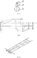
- Fig. 1 shows variants of the bi-metal frame
- Fig. 1a shows the variant with the truss and 1b with two parallel reinforcing beams.
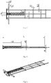
- Fig. 2 presents the embodiment with the use of the reinforcing frame with the range of reinforcing beams, where Fig. 2a shows details of the frame from the side, Fig. 2b a cross-section of the reinforcing beam, and Fig. 2c a view of the frame from the top, and Fig. 2d an axonometric view from the side of the robot wrist.
- Fig. 3 presents the embodiment with the use of the reinforcing frame from the truss, where Fig. 3a shows details of the frame from the top, Fig. 3b a view of the frame from the side, and Fig. 3c an axonometric view from the side of the robot wrist.
- the reinforcements of the main beam in a form of additional reinforcing beams, additional frame structure, are mounted at the base of the gripper frame from the side of the robot wrist, are made of the steel of lesser thermal expansion, for example low-carbon steel of common quality which thermal expansion coefficient is 10,5 ⁇ 12 ⁇ 10-6 K -1 .
- the types of steel to be used should be selected such that the difference of the thermal expansion values of both said parts should be between 15% and 25%. Such a solution provides automatic compensation of the thermal deformation, which increases the accuracy of the positioning of the forms in the furnace.
- a gripper frame presented in Fig. 2 is a frame structure welded with reinforcing beams, preferably tubes.
- the main beam 1 of diameter D and length L and the reinforcing beams 4, 5 of diameter D1 and D2 and of a length respectively L1 and L2 are stiffened by a sheet of a thickness from 1 to 4 mm.
- the length of the main supporting beam L is from 2000 mm to 2600 mm.
- the gripper on one side is terminated with a fastening to a robot wrist 6. It is made of a sheet of a thickness from 12 to 18 mm.
- the main supporting beams 1 of diameter D, gripper arms 2 and the fastening to the robot wrist 6 are made of stainless steel of thermal expansion from 15% to 25% greater than a connected with the whole by welding method reinforcement 2 made of carbon steel tubes.
- L1 in the gripper is equal (0.35 ⁇ 0.5) the gripper length L.
- the length of the beam 5 of the reinforcement referred to in Fig. 2 as L2 in the gripper is equal 0.5 ⁇ 0.8 of the beam length L.
- All the construction elements of the gripper described above are connected with each other by means of electric welding with filet and butt welds. Other mechanical connections between the structure elements of the gripper may be used, such as: bolted connections, riveting, bonding.
- a gripper frame presented in Fig. 3 is a structure welded with two frames, a supporting frame and reinforcing frame.
- the supporting frame of length L equal from 2000 mm to 2600 mm and width from 300 mm to 600 mm is made of tubes of diameter D equal from 60 to 80 mm and a wall thickness 1.5 to 3 mm, D1 equal 30 to 35 mm and a wall thickness from 1.2 to 2 mm , D2 equal from 10 to 15 mm and a wall thickness from 0.8 to 1.6 mm.
- the supporting frame is made of stainless steel which thermal expansion coefficient is 15 ⁇ 17 ⁇ 10 -6 K -1 .
- the supporting frame is permanently connected, by means of a welded connection, with the reinforcing frame.
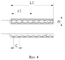
- the reinforcing frame ( Fig.
- the reinforcing frame is made from pipes of diameter d equal from 14 to 16 mm and a wall thickness from 1 to 2 mm. Width b of the reinforcing frame is equal from 100 to 120 mm and height a1 is from 40 to 70 mm.
- the reinforcing frame is divided into 7 - 9 equal sections, so called segments, of length c. Each section is determined by diagonally located beams forming the reinforcing frame.
- the reinforcing frame is made of low-carbon steel of common quality which thermal expansion coefficient is 10,5 ⁇ 12 ⁇ 10 -6 K -1 .
- the supporting frame is made of steel of thermal expansion from 15% to 25% greater than the reinforcing frame. All the elements of the gripper described above are connected with each other by means of electric welding with fillet and butt welds. Other mechanical connections may be used, such as: bolted connections, riveting, bonding.
Landscapes
- Engineering & Computer Science (AREA)
- Robotics (AREA)
- Mechanical Engineering (AREA)
- Manipulator (AREA)
- Bending Of Plates, Rods, And Pipes (AREA)
Abstract
Description
- The present invention relates to a bi-metal frame structure for an industrial robot gripper, designed to handle flat blanks on a production line, in particular while manipulating the blanks in extremely high temperature, above 800 °C, where structurally compensated are flexural thermal deformations.
- Hot stamping technological process is performed in high temperature, particularly while uploading to and unloading of the blanks from the furnace. The furnace chamber temperature is between 800 °C and 950 °C. From the patent description
CN111112418 is known a sheet part stamping process that relates to a field of sheet parts machining processes. The sheet part stamping process includes the following steps: - stainless steel sheet is cut in order to obtain a required sheet, the sheet is placed in the heating furnace in order to heat up to 840-900 °C with the heating speed of 30-40 °C / min, heat maintenance during 20-40 minutes and then cooling down of the furnace;
- in the die sprayed is a layer of a high temperature resistant lubricant, the die is pre-heated to 240-300 °C and undergoes hot treatment, when the temperature of the metal plate is lowered such to correspond to the temperature of the die, the metal plate is clamped with a mechanical arm to provide fast transfer to the die, which is to undergo forming by punching, the natural cooling to the room temperature takes place and the semi-finished sheet part is produced; and
- a sheet is placed in the heating furnace in order to heat up to 180-200 °C, air cooling to room temperature following the temperature maintenance for 10-15 minutes, and the blank can be retrieved when washed with clean water. The method has advantages such that the difficulty of the process is little, the dimensions of the sheet part are stable, thickness distribution is uniform and cracks or deformations do not occur.
- Due to operations in such high temperatures, the process is automated, performed by means of industrial robots. To the robot wrist mounted is a special gripper. A typical frame structure of the gripper is a welded frame structure made from closed profiles of rectangular or square cross-sections, comprising a main supporting beam to which relevant arms are mounted thereto. On said arms mounted are relevant gripping devices, in a form of jaws, which have a task to clearly hold and position the blanks in the defined and unchanging position during manipulation thereof. The gripper structure provides automatic closing and opening of the clamping units.
- Said gripper has a task to collect the blank (flat sheet matrix of a defined shape) from the warehouse and transfer it to a heated up to a high temperature (above 800 °C) relevant furnace chamber. Another task of said gripper is to collect the heated blank from the furnace chamber and transfer it to the punch where the sheet will be formed to the final shape. The furnace is composed of several chambers (from two to five) which are located one above the another. The robot with the mounted to the wrist thereof gripper with the collected blank transfers said blank to the selected furnace chamber, withdrawal of the empty gripper takes place, the furnace chamber closes and another furnace chamber opens, the robot places the gripper in the open chamber and collects the heated blanks therefrom and transfers them to the punch. The process is repeated consecutively. Due to the operations in extremely high temperatures, it is typically cooled by air which flows within the supporting structure beams. During serial production, the gripper frame, while transferring the blanks, heats up (absorbing the furnace heat). Having reached a steady operating temperature (150 °C - 200 °C), which is significantly higher than the ambient temperature, the gripper frame deforms. Such deformation is in a form of a bend of the supporting frame towards gravitational pull. In the ambient temperature, the gripper frame bend is little and derives exclusively from the weight of the transferred blanks and self-weight of the structure. Following the heating of the gripper frame up to the operational temperature (150 °C - 200 °C) an additional deflection occurs, which is significantly greater than the initial bend deriving from the self-weight and weight of the blanks. Said additional deformation is a very disadvantageous phenomenon, in particular during positioning of the gripper prior to inserting to the furnace chamber. Said deformation unables accurate positioning of the gripper with the blanks in relation to each of the furnace chamber. A very disadvantageous phenomenon, having the impact on the automation process, is the increase of the gripper deformation from the initial value when the gripper is of the room temperature, to the maximum when the gripper has reached the operating temperature. At that time, a gradual increase of the gripper deformation takes place and the position thereof in relation to the furnace chamber changes. It may result in the gripper collision with the furnace during automatic operation of the production line.
- The subject-matter of the new, bi-metal gripper frame is the use of steel of two different thermal expansion values in the structure of the gripper supporting beam. The main supporting beam, arms and fastening to the robot wrist are made of the steel of a greater thermal expansion, for example of stainless steel of austenitic, ferritic, martensitic or ferritic-austensitic type, which thermal expansion coefficient is 15 ÷ 17∗ 10-6K-1.
- The subject of the invention is presented in the embodiment in the drawing, where
Fig. 1 shows variants of the bi-metal frame, whereFig. 1a shows the variant with the truss and 1b with two parallel reinforcing beams.Fig. 2 presents the embodiment with the use of the reinforcing frame with the range of reinforcing beams, whereFig. 2a shows details of the frame from the side,Fig. 2b a cross-section of the reinforcing beam, andFig. 2c a view of the frame from the top, andFig. 2d an axonometric view from the side of the robot wrist.Fig. 3 presents the embodiment with the use of the reinforcing frame from the truss, whereFig. 3a shows details of the frame from the top,Fig. 3b a view of the frame from the side, andFig. 3c an axonometric view from the side of the robot wrist. - Such a solution, that is the use of the steels of different thermal expansion coefficients, provides automatic compensation of the thermal deformation, which increases the accuracy of the positioning of the blanks in the furnace.
- The reinforcements of the main beam in a form of additional reinforcing beams, additional frame structure, are mounted at the base of the gripper frame from the side of the robot wrist, are made of the steel of lesser thermal expansion, for example low-carbon steel of common quality which thermal expansion coefficient is 10,5 ÷ 12∗10-6 K-1. The types of steel to be used should be selected such that the difference of the thermal expansion values of both said parts should be between 15% and 25%. Such a solution provides automatic compensation of the thermal deformation, which increases the accuracy of the positioning of the forms in the furnace.
- A gripper frame presented in
Fig. 2 is a frame structure welded with reinforcing beams, preferably tubes. The frame dimensions are within the range: width from 300mm to 500 mm and length 1800mm to 2500 mm. It comprises welded with each other main supportingbeams 1 of diameter D equal 60 to 80 mm and a wall thickness 1.5 to 3 mm, the two reinforcingbeams wall thickness 1 to 3 mm and D2 = from 24 to 30 mm,arms 2 from tubes of diameter D3= from 30 to 35 mm and a wall thickness from 1.2 to 2 mm and D4 from 10 to 15 mm and a wall thickness from 0.8 to 1.6 mm. Supplementary, themain beam 1 of diameter D and length L and the reinforcingbeams robot wrist 6. It is made of a sheet of a thickness from 12 to 18 mm. The main supportingbeams 1 of diameter D,gripper arms 2 and the fastening to therobot wrist 6 are made of stainless steel of thermal expansion from 15% to 25% greater than a connected with the whole bywelding method reinforcement 2 made of carbon steel tubes. The length of thebeam 4 of the reinforcement referred to inFig. 2 as L1 in the gripper is equal (0.35÷0.5) the gripper length L. The length of thebeam 5 of the reinforcement referred to inFig. 2 as L2 in the gripper is equal 0.5 ÷ 0.8 of the beam length L. All the construction elements of the gripper described above are connected with each other by means of electric welding with filet and butt welds. Other mechanical connections between the structure elements of the gripper may be used, such as: bolted connections, riveting, bonding. - A gripper frame presented in
Fig. 3 is a structure welded with two frames, a supporting frame and reinforcing frame. The supporting frame of length L equal from 2000 mm to 2600 mm and width from 300 mm to 600 mm is made of tubes of diameter D equal from 60 to 80 mm and a wall thickness 1.5 to 3 mm, D1 equal 30 to 35 mm and a wall thickness from 1.2 to 2 mm , D2 equal from 10 to 15 mm and a wall thickness from 0.8 to 1.6 mm. The supporting frame is made of stainless steel which thermal expansion coefficient is 15 ÷17∗ 10-6K-1. The supporting frame is permanently connected, by means of a welded connection, with the reinforcing frame. The reinforcing frame (Fig. 4 ) has length L1 which is equal (0,35÷0,5) the supporting frame total length L. The reinforcing frame is made from pipes of diameter d equal from 14 to 16 mm and a wall thickness from 1 to 2 mm. Width b of the reinforcing frame is equal from 100 to 120 mm and height a1 is from 40 to 70 mm. The reinforcing frame is divided into 7 - 9 equal sections, so called segments, of length c. Each section is determined by diagonally located beams forming the reinforcing frame. The reinforcing frame is made of low-carbon steel of common quality which thermal expansion coefficient is 10,5÷12∗ 10-6K-1. The supporting frame is made of steel of thermal expansion from 15% to 25% greater than the reinforcing frame. All the elements of the gripper described above are connected with each other by means of electric welding with fillet and butt welds. Other mechanical connections may be used, such as: bolted connections, riveting, bonding.
Claims (7)
- A supporting frame for an industrial robot comprising welded with each other a main supporting beam (1) and arms (2), which are mounted to a robot wrist (6), characterized in that from the upper side of the supporting frame at the robot wrist mounted is a reinforcing frame in a form of reinforcing beams (4, 5) oriented alongside the main supporting beam or space truss, for which the difference of thermal expansion values between the supporting frame and reinforcing frame of lesser thermal expansion is 15% - 25%.
- The frame according to Claim 1, characterized in that the supporting frame is made of stainless steel of thermal expansion 15 ÷ 17∗ 10-6K-1.
- The frame according to Claim 1, characterized in that the reinforcing frame is made of low-carbon steel of thermal expansion 10.5 ÷ 12∗ 10-6 K-1.
- The frame according to Claim 1, characterized in that the length of the beam (4) of reinforcement L1 in the gripper is equal (0.35÷0.5) the gripper length L.
- The frame according to Claim 1, characterized in that the length of the beam (5) of reinforcement L2 in the gripper is equal 0.5 ÷ 0.8 of the gripper length L.
- The frame according to Claim 1, characterized in that the reinforcing frame has length L1 which is equal 0.35 to 0.5 of the gripper length L.
- The frame according to Claim 1, characterized in that the reinforcing frame from the truss is divided into 7 - 9 sections.
Applications Claiming Priority (1)
| Application Number | Priority Date | Filing Date | Title |
|---|---|---|---|
| PL436319A PL242729B1 (en) | 2020-12-11 | 2020-12-11 | Frame for an industrial robot gripper |
Related Parent Applications (1)
| Application Number | Title | Priority Date | Filing Date |
|---|---|---|---|
| PL436319A Previously-Filed-Application PL242729B1 (en) | 2020-12-11 | 2020-12-11 | Frame for an industrial robot gripper |
Publications (3)
| Publication Number | Publication Date |
|---|---|
| EP4019199A1 true EP4019199A1 (en) | 2022-06-29 |
| EP4019199C0 EP4019199C0 (en) | 2024-09-25 |
| EP4019199B1 EP4019199B1 (en) | 2024-09-25 |
Family
ID=78851257
Family Applications (1)
| Application Number | Title | Priority Date | Filing Date |
|---|---|---|---|
| EP21210421.0A Active EP4019199B1 (en) | 2020-12-11 | 2021-11-25 | Frame structure for for industrial robot gripper |
Country Status (2)
| Country | Link |
|---|---|
| EP (1) | EP4019199B1 (en) |
| PL (1) | PL242729B1 (en) |
Citations (6)
| Publication number | Priority date | Publication date | Assignee | Title |
|---|---|---|---|---|
| US4092755A (en) * | 1977-03-18 | 1978-06-06 | Hughes Gary W | Highly versatile dock trailer |
| JPH09242564A (en) * | 1996-02-29 | 1997-09-16 | Senshin Zairyo Riyou Gas Jienereeta Kenkyusho:Kk | Fastening structure of composite liner |
| EP1927483A1 (en) * | 2006-12-01 | 2008-06-04 | Schenck RoTec GmbH | Device for mounting a pneumatic tyre onto a vehicle wheel rim |
| CN107234186A (en) * | 2016-03-28 | 2017-10-10 | 宝山钢铁股份有限公司 | A kind of lightweight clamper of drop stamping blank |
| CN108792969A (en) * | 2018-07-06 | 2018-11-13 | 陈荣乾 | A kind of Lifting device of crane |
| CN111112418A (en) | 2019-12-04 | 2020-05-08 | 苏州格鼎精密电子有限公司 | Metal sheet metal part stamping process |
-
2020
- 2020-12-11 PL PL436319A patent/PL242729B1/en unknown
-
2021
- 2021-11-25 EP EP21210421.0A patent/EP4019199B1/en active Active
Patent Citations (6)
| Publication number | Priority date | Publication date | Assignee | Title |
|---|---|---|---|---|
| US4092755A (en) * | 1977-03-18 | 1978-06-06 | Hughes Gary W | Highly versatile dock trailer |
| JPH09242564A (en) * | 1996-02-29 | 1997-09-16 | Senshin Zairyo Riyou Gas Jienereeta Kenkyusho:Kk | Fastening structure of composite liner |
| EP1927483A1 (en) * | 2006-12-01 | 2008-06-04 | Schenck RoTec GmbH | Device for mounting a pneumatic tyre onto a vehicle wheel rim |
| CN107234186A (en) * | 2016-03-28 | 2017-10-10 | 宝山钢铁股份有限公司 | A kind of lightweight clamper of drop stamping blank |
| CN108792969A (en) * | 2018-07-06 | 2018-11-13 | 陈荣乾 | A kind of Lifting device of crane |
| CN111112418A (en) | 2019-12-04 | 2020-05-08 | 苏州格鼎精密电子有限公司 | Metal sheet metal part stamping process |
Also Published As
| Publication number | Publication date |
|---|---|
| PL242729B1 (en) | 2023-04-11 |
| PL436319A1 (en) | 2022-06-13 |
| EP4019199C0 (en) | 2024-09-25 |
| EP4019199B1 (en) | 2024-09-25 |
Similar Documents
| Publication | Publication Date | Title |
|---|---|---|
| EP2433723B1 (en) | Bending device | |
| US6810709B2 (en) | Heated metal forming tool | |
| DK2576096T3 (en) | Conversion method for heat conversion of a steel plate of a rotor blade to be manufactured by a wind power plant | |
| US20220258223A1 (en) | Press systems and methods | |
| EA024541B1 (en) | Bending device | |
| CN104057263A (en) | Large-scale locomotive connecting rod forging technology | |
| CN109433860B (en) | Integral thermal shaping device and method for cabin body opening cover | |
| RU2220020C1 (en) | Method of manufacture of forgings, predominantly out of metals and alloys of titanium subgroup and forging complex for performing the same | |
| CN105382167B (en) | Ultra-fine grain titanium alloy sheath and its Compound Extrusion shaping dies and method | |
| EP4019199B1 (en) | Frame structure for for industrial robot gripper | |
| EP4476010B1 (en) | Isothermal forging system | |
| CN116550918B (en) | A stamping forming method for complex heads | |
| Shingledecker et al. | Materials improvements for improved economy of high-temperature components in future gen 3 CSP systems | |
| US6799450B2 (en) | Method of stretch forming an aluminum metal sheet and handling equipment for doing the same | |
| JP4536838B2 (en) | Method for manufacturing sandwich panel | |
| Qiu et al. | Experimental investigation on process parameters of laser-assisted robotic roller bending of a thin-walled structure | |
| CN113477763B (en) | Automatic stainless steel pipe bending equipment and pipe bending processing technology | |
| CN116550917B (en) | A large complex head forging forming method and forming tooling | |
| CN115989134B (en) | Manufacturing methods for pressed molded products and the trays and hot pressing production lines used therein | |
| US12435386B2 (en) | Intermediate heating station with support projections on lower mask | |
| CN117564198A (en) | A high-pressure flange automated forging production process | |
| CN118321475B (en) | A forging process for high temperature alloy | |
| US4714499A (en) | Full length forging method for producing large section, large mass cylindrical sleeves of alloy 625 | |
| US4781768A (en) | Full length forging method for producing large section, large mass cylindrical sleeves of alloy 625 | |
| Grodotzki et al. | Investigation of Warping and Springback |
Legal Events
| Date | Code | Title | Description |
|---|---|---|---|
| PUAI | Public reference made under article 153(3) epc to a published international application that has entered the european phase |
Free format text: ORIGINAL CODE: 0009012 |
|
| STAA | Information on the status of an ep patent application or granted ep patent |
Free format text: STATUS: THE APPLICATION HAS BEEN PUBLISHED |
|
| AK | Designated contracting states |
Kind code of ref document: A1 Designated state(s): AL AT BE BG CH CY CZ DE DK EE ES FI FR GB GR HR HU IE IS IT LI LT LU LV MC MK MT NL NO PL PT RO RS SE SI SK SM TR |
|
| STAA | Information on the status of an ep patent application or granted ep patent |
Free format text: STATUS: REQUEST FOR EXAMINATION WAS MADE |
|
| 17P | Request for examination filed |
Effective date: 20220831 |
|
| RBV | Designated contracting states (corrected) |
Designated state(s): AL AT BE BG CH CY CZ DE DK EE ES FI FR GB GR HR HU IE IS IT LI LT LU LV MC MK MT NL NO PL PT RO RS SE SI SK SM TR |
|
| STAA | Information on the status of an ep patent application or granted ep patent |
Free format text: STATUS: EXAMINATION IS IN PROGRESS |
|
| RIC1 | Information provided on ipc code assigned before grant |
Ipc: B25J 15/00 20060101ALI20221219BHEP Ipc: B25J 9/00 20060101AFI20221219BHEP |
|
| 17Q | First examination report despatched |
Effective date: 20230104 |
|
| GRAP | Despatch of communication of intention to grant a patent |
Free format text: ORIGINAL CODE: EPIDOSNIGR1 |
|
| STAA | Information on the status of an ep patent application or granted ep patent |
Free format text: STATUS: GRANT OF PATENT IS INTENDED |
|
| GRAS | Grant fee paid |
Free format text: ORIGINAL CODE: EPIDOSNIGR3 |
|
| INTG | Intention to grant announced |
Effective date: 20240726 |
|
| GRAA | (expected) grant |
Free format text: ORIGINAL CODE: 0009210 |
|
| STAA | Information on the status of an ep patent application or granted ep patent |
Free format text: STATUS: THE PATENT HAS BEEN GRANTED |
|
| AK | Designated contracting states |
Kind code of ref document: B1 Designated state(s): AL AT BE BG CH CY CZ DE DK EE ES FI FR GB GR HR HU IE IS IT LI LT LU LV MC MK MT NL NO PL PT RO RS SE SI SK SM TR |
|
| REG | Reference to a national code |
Ref country code: GB Ref legal event code: FG4D |
|
| REG | Reference to a national code |
Ref country code: CH Ref legal event code: EP |
|
| REG | Reference to a national code |
Ref country code: DE Ref legal event code: R096 Ref document number: 602021019247 Country of ref document: DE |
|
| REG | Reference to a national code |
Ref country code: IE Ref legal event code: FG4D |
|
| U01 | Request for unitary effect filed |
Effective date: 20241015 |
|
| U07 | Unitary effect registered |
Designated state(s): AT BE BG DE DK EE FI FR IT LT LU LV MT NL PT RO SE SI Effective date: 20241022 |
|
| U20 | Renewal fee for the european patent with unitary effect paid |
Year of fee payment: 4 Effective date: 20241108 |
|
| PG25 | Lapsed in a contracting state [announced via postgrant information from national office to epo] |
Ref country code: NO Free format text: LAPSE BECAUSE OF FAILURE TO SUBMIT A TRANSLATION OF THE DESCRIPTION OR TO PAY THE FEE WITHIN THE PRESCRIBED TIME-LIMIT Effective date: 20241225 |
|
| PG25 | Lapsed in a contracting state [announced via postgrant information from national office to epo] |
Ref country code: GR Free format text: LAPSE BECAUSE OF FAILURE TO SUBMIT A TRANSLATION OF THE DESCRIPTION OR TO PAY THE FEE WITHIN THE PRESCRIBED TIME-LIMIT Effective date: 20241226 |
|
| PG25 | Lapsed in a contracting state [announced via postgrant information from national office to epo] |
Ref country code: RS Free format text: LAPSE BECAUSE OF FAILURE TO SUBMIT A TRANSLATION OF THE DESCRIPTION OR TO PAY THE FEE WITHIN THE PRESCRIBED TIME-LIMIT Effective date: 20241225 |
|
| PG25 | Lapsed in a contracting state [announced via postgrant information from national office to epo] |
Ref country code: RS Free format text: LAPSE BECAUSE OF FAILURE TO SUBMIT A TRANSLATION OF THE DESCRIPTION OR TO PAY THE FEE WITHIN THE PRESCRIBED TIME-LIMIT Effective date: 20241225 Ref country code: NO Free format text: LAPSE BECAUSE OF FAILURE TO SUBMIT A TRANSLATION OF THE DESCRIPTION OR TO PAY THE FEE WITHIN THE PRESCRIBED TIME-LIMIT Effective date: 20241225 Ref country code: GR Free format text: LAPSE BECAUSE OF FAILURE TO SUBMIT A TRANSLATION OF THE DESCRIPTION OR TO PAY THE FEE WITHIN THE PRESCRIBED TIME-LIMIT Effective date: 20241226 |
|
| PG25 | Lapsed in a contracting state [announced via postgrant information from national office to epo] |
Ref country code: IS Free format text: LAPSE BECAUSE OF FAILURE TO SUBMIT A TRANSLATION OF THE DESCRIPTION OR TO PAY THE FEE WITHIN THE PRESCRIBED TIME-LIMIT Effective date: 20250125 |
|
| PG25 | Lapsed in a contracting state [announced via postgrant information from national office to epo] |
Ref country code: SM Free format text: LAPSE BECAUSE OF FAILURE TO SUBMIT A TRANSLATION OF THE DESCRIPTION OR TO PAY THE FEE WITHIN THE PRESCRIBED TIME-LIMIT Effective date: 20240925 |
|
| PG25 | Lapsed in a contracting state [announced via postgrant information from national office to epo] |
Ref country code: ES Free format text: LAPSE BECAUSE OF FAILURE TO SUBMIT A TRANSLATION OF THE DESCRIPTION OR TO PAY THE FEE WITHIN THE PRESCRIBED TIME-LIMIT Effective date: 20240925 |
|
| PG25 | Lapsed in a contracting state [announced via postgrant information from national office to epo] |
Ref country code: PL Free format text: LAPSE BECAUSE OF FAILURE TO SUBMIT A TRANSLATION OF THE DESCRIPTION OR TO PAY THE FEE WITHIN THE PRESCRIBED TIME-LIMIT Effective date: 20240925 Ref country code: CZ Free format text: LAPSE BECAUSE OF FAILURE TO SUBMIT A TRANSLATION OF THE DESCRIPTION OR TO PAY THE FEE WITHIN THE PRESCRIBED TIME-LIMIT Effective date: 20240925 |
|
| PG25 | Lapsed in a contracting state [announced via postgrant information from national office to epo] |
Ref country code: SK Free format text: LAPSE BECAUSE OF FAILURE TO SUBMIT A TRANSLATION OF THE DESCRIPTION OR TO PAY THE FEE WITHIN THE PRESCRIBED TIME-LIMIT Effective date: 20240925 |
|
| REG | Reference to a national code |
Ref country code: CH Ref legal event code: PL |
|
| PG25 | Lapsed in a contracting state [announced via postgrant information from national office to epo] |
Ref country code: MC Free format text: LAPSE BECAUSE OF FAILURE TO SUBMIT A TRANSLATION OF THE DESCRIPTION OR TO PAY THE FEE WITHIN THE PRESCRIBED TIME-LIMIT Effective date: 20240925 |
|
| REG | Reference to a national code |
Ref country code: CH Ref legal event code: PL |
|
| PG25 | Lapsed in a contracting state [announced via postgrant information from national office to epo] |
Ref country code: CH Free format text: LAPSE BECAUSE OF NON-PAYMENT OF DUE FEES Effective date: 20241130 |
|
| PLBE | No opposition filed within time limit |
Free format text: ORIGINAL CODE: 0009261 |
|
| STAA | Information on the status of an ep patent application or granted ep patent |
Free format text: STATUS: NO OPPOSITION FILED WITHIN TIME LIMIT |
|
| 26N | No opposition filed |
Effective date: 20250626 |
|
| PG25 | Lapsed in a contracting state [announced via postgrant information from national office to epo] |
Ref country code: IE Free format text: LAPSE BECAUSE OF NON-PAYMENT OF DUE FEES Effective date: 20241125 |
|
| U20 | Renewal fee for the european patent with unitary effect paid |
Year of fee payment: 5 Effective date: 20251106 |
|
| PG25 | Lapsed in a contracting state [announced via postgrant information from national office to epo] |
Ref country code: HR Free format text: LAPSE BECAUSE OF FAILURE TO SUBMIT A TRANSLATION OF THE DESCRIPTION OR TO PAY THE FEE WITHIN THE PRESCRIBED TIME-LIMIT Effective date: 20240925 |
|
| PG25 | Lapsed in a contracting state [announced via postgrant information from national office to epo] |
Ref country code: HU Free format text: LAPSE BECAUSE OF FAILURE TO SUBMIT A TRANSLATION OF THE DESCRIPTION OR TO PAY THE FEE WITHIN THE PRESCRIBED TIME-LIMIT; INVALID AB INITIO Effective date: 20211125 |
|
| PG25 | Lapsed in a contracting state [announced via postgrant information from national office to epo] |
Ref country code: CY Free format text: LAPSE BECAUSE OF FAILURE TO SUBMIT A TRANSLATION OF THE DESCRIPTION OR TO PAY THE FEE WITHIN THE PRESCRIBED TIME-LIMIT; INVALID AB INITIO Effective date: 20211125 |
|
| PG25 | Lapsed in a contracting state [announced via postgrant information from national office to epo] |
Ref country code: TR Free format text: LAPSE BECAUSE OF FAILURE TO SUBMIT A TRANSLATION OF THE DESCRIPTION OR TO PAY THE FEE WITHIN THE PRESCRIBED TIME-LIMIT Effective date: 20240925 |