EP4019153A1 - Jet nozzle for powder handling apparatus - Google Patents
Jet nozzle for powder handling apparatus Download PDFInfo
- Publication number
- EP4019153A1 EP4019153A1 EP21215934.7A EP21215934A EP4019153A1 EP 4019153 A1 EP4019153 A1 EP 4019153A1 EP 21215934 A EP21215934 A EP 21215934A EP 4019153 A1 EP4019153 A1 EP 4019153A1
- Authority
- EP
- European Patent Office
- Prior art keywords
- jet nozzle
- spray opening
- interior surface
- ceiling
- air
- Prior art date
- Legal status (The legal status is an assumption and is not a legal conclusion. Google has not performed a legal analysis and makes no representation as to the accuracy of the status listed.)
- Granted
Links
Images




Classifications
-
- B—PERFORMING OPERATIONS; TRANSPORTING
- B01—PHYSICAL OR CHEMICAL PROCESSES OR APPARATUS IN GENERAL
- B01F—MIXING, e.g. DISSOLVING, EMULSIFYING OR DISPERSING
- B01F35/00—Accessories for mixers; Auxiliary operations or auxiliary devices; Parts or details of general application
- B01F35/10—Maintenance of mixers
- B01F35/145—Washing or cleaning mixers not provided for in other groups in this subclass; Inhibiting build-up of material on machine parts using other means
- B01F35/1452—Washing or cleaning mixers not provided for in other groups in this subclass; Inhibiting build-up of material on machine parts using other means using fluids
- B01F35/1453—Washing or cleaning mixers not provided for in other groups in this subclass; Inhibiting build-up of material on machine parts using other means using fluids by means of jets of fluid, e.g. air
-
- B—PERFORMING OPERATIONS; TRANSPORTING
- B01—PHYSICAL OR CHEMICAL PROCESSES OR APPARATUS IN GENERAL
- B01F—MIXING, e.g. DISSOLVING, EMULSIFYING OR DISPERSING
- B01F27/00—Mixers with rotary stirring devices in fixed receptacles; Kneaders
- B01F27/60—Mixers with rotary stirring devices in fixed receptacles; Kneaders with stirrers rotating about a horizontal or inclined axis
- B01F27/62—Mixers with rotary stirring devices in fixed receptacles; Kneaders with stirrers rotating about a horizontal or inclined axis comprising liquid feeding, e.g. spraying means
-
- B—PERFORMING OPERATIONS; TRANSPORTING
- B01—PHYSICAL OR CHEMICAL PROCESSES OR APPARATUS IN GENERAL
- B01F—MIXING, e.g. DISSOLVING, EMULSIFYING OR DISPERSING
- B01F27/00—Mixers with rotary stirring devices in fixed receptacles; Kneaders
- B01F27/60—Mixers with rotary stirring devices in fixed receptacles; Kneaders with stirrers rotating about a horizontal or inclined axis
- B01F27/70—Mixers with rotary stirring devices in fixed receptacles; Kneaders with stirrers rotating about a horizontal or inclined axis with paddles, blades or arms
-
- B—PERFORMING OPERATIONS; TRANSPORTING
- B08—CLEANING
- B08B—CLEANING IN GENERAL; PREVENTION OF FOULING IN GENERAL
- B08B9/00—Cleaning hollow articles by methods or apparatus specially adapted thereto
- B08B9/08—Cleaning containers, e.g. tanks
- B08B9/093—Cleaning containers, e.g. tanks by the force of jets or sprays
-
- B—PERFORMING OPERATIONS; TRANSPORTING
- B01—PHYSICAL OR CHEMICAL PROCESSES OR APPARATUS IN GENERAL
- B01F—MIXING, e.g. DISSOLVING, EMULSIFYING OR DISPERSING
- B01F2101/00—Mixing characterised by the nature of the mixed materials or by the application field
- B01F2101/06—Mixing of food ingredients
Definitions
- the invention relates to an apparatus for handling a food product powder and to a method for cleaning an apparatus for handling a food product power.
- Food product powders may be used to produce various food products. Using such product powders are advantageous in that the powder may be stored for long periods of time without being spoiled, compared to liquid food products. The food powder may also be easily dissolved in a liquid to form the desired food product.
- Food products formed by powders may include dairy beverages, such as milk, non-dairy beverages, such as soft drinks, and other dairy products such as ice cream, yogurt, or cheese.
- Product powders may include raw materials such as sugar, milk powder, salt, or flour, and finished products such as instant formula, instant drinks, or dry broth.
- raw milk powder may be used. The raw milk powder dissolves easily in water to form a reconstituted liquid milk that may undergo further processing, including filtration, homogenization, and heat treatment, to form the final food product.
- Product powders may require a mixing process which typically occurs in a sealable container including a stirring arrangement, paddle mixers, or other suitable mixing devices. After mixing occurs and the product mixture is removed from the sealable container, a residual powder may remain on the interior walls of the sealable container.
- a conventional method for cleaning the interior walls includes maintenance personnel manually removing the powder using compressed air. The conventional cleaning method is deficient in that the cleaning process is labor-intensive. The conventional cleaning method may also require opening the container, thereby causing the container interior to be susceptible to contamination.
- an apparatus for handling a food product powder includes a sealable container having an interior surface defining a volume in which the food product powder is handled, and a powder outlet, and a nozzle that is attached to the sealable container and configured to feed air into the sealable container and direct the air towards the interior surface to remove product powder from the interior surface, such that the air and the removed product powder may flow out of the sealable container via the powder outlet.
- the jet nozzle includes a ceiling spray opening formed on a first side of the jet nozzle and directed towards a ceiling of the interior surface, and a side wall spray opening formed on a second side of the jet nozzle opposite the first side and directed towards a side wall of the interior surface.
- the cleaning according to the invention is not done in the traditional way, i.e. by opening the container and manually using compressed air to remove the powder from the interior surface and out of the container. Instead, the powder is removed from the interior surface using the jet nozzle that directs the air towards different surfaces of the interior, such as the ceiling and side wall, and the removed powder and air may be drawn out of the container.
- the apparatus for handling a food product powder described herein is advantageous in that the apparatus enables cleaning in a very efficient and sanitary manner.
- the container may remain closed during the cleaning process.
- the apparatus may include more than one jet nozzle that is arranged to direct the flow of air towards different interior surfaces of the container.
- the arrangement of the jet nozzles is advantageous in ensuring that the powder is removed from the different interior surfaces of the container and directed to a location to be drawn out of the container.
- a method for cleaning is used for an apparatus for handling a food product powder that includes a sealable container having an interior surface defining a volume in which the food product powder is handled, and a powder outlet.
- the method includes feeding air into the sealable container using a jet nozzle that is attached to the sealable container, with the air being directed by the jet nozzle towards the interior surface to remove product powder from the interior surface, directing air towards a ceiling of the interior surface using a ceiling spray opening formed on a first side of the jet nozzle, and towards a side wall of the interior surface using a side wall spray opening formed on a second side of the jet nozzle opposite the first side, and drawing air out from the sealable container, such that air and the removed product powder may flow out of the sealable container via the powder outlet.
- This method may include the same features as the apparatus for handling a food product powder and shares the same advantages.
- the apparatus 1 includes a sealable container 2 having an interior surface 3 that defines a volume 4 in which the food product powder is handled, and a powder outlet 5.
- the apparatus 1 may be oriented horizontally such that the powder outlet 5 is arranged at a bottom of the apparatus 1.
- One or more jet nozzles 6 are attached to the container 2 and are configured to feed air into the container 2 for removing residual food product powder from the container 2 during a cleaning process that occurs after a bulk of the food product powder is removed from the container 2. The bulk of the food product powder is removed from the container 2 for further processing to produce a food product.
- Each jet nozzle 6 is configured to direct the air towards different surfaces of the interior surface 3 to remove the product powder from the interior surface 3.
- the different surfaces include at least a ceiling 7 and a side wall 8. After the product powder is removed from the interior surface 3, the air and the removed product powder exit the container 2 via the powder outlet 5.
- Handling the food product powder in the container 2 may include stirring or mixing the food product powder.
- the food product powder may be any combination of milk powder, sugar, salt, or flour, or powder mixtures such as infant formula, cake and baking mixtures and similar food product powders.
- the apparatus 1 may be any apparatus that handles food product powder, such as a storage tank or mixers.
- the apparatus 1 is a mixer.
- the apparatus 1 has then a rotatable stirring device 9, 10 for stirring or mixing the product powder mounted to a back wall 11 of the container 2.
- the rotatable stirring device 9, 10 extends through the volume 4 of the container 2 when the apparatus 1 is assembled.
- the rotatable stirring device 9, 10 may include one or more rotatable shafts 9 that include mixing paddles 10. If more than one rotatable shaft 9 is provided, the rotatable shafts 9 may be arranged to counterrotate relative to each other.
- the shape of the container 2 may be formed to accommodate rotation of the one or more rotatable shafts 9 and mixing paddles 10.
- the interior surface 3 of the container 2 is defined by the side wall 8, the ceiling 7, the back wall 11, and a front wall arranged opposite the back wall 11.
- the front wall may be formed as a pivotable door 12.
- the door 12 may be attached to the container 2 via hinges and handles 12a.
- the ceiling 7 extends from the side wall 8 to another side wall 13 arranged opposite to the side wall 8, and between the back wall 11 and the door 12.
- the side walls 8, 13 may be angled relative to the ceiling 7 that is substantially planar and extends horizontally.
- the jet nozzles 6 are mounted to the ceiling 7 of the container 2 at a portion of the container 2 at which the ceiling 7 transitions to the side wall 8. Each of the jet nozzles 6 are positioned to direct a flow of air towards one or more of the ceiling 7, the side wall 8, the rotatable stirring device 9, 10, and the door 12.
- An actuator 14 is connected to each jet nozzle 6 and configured to actuate the jet nozzle 6 by displacing the jet nozzle 6 along its axis to push it into the volume 4.
- jet nozzles 6 may be provided and the arrangement of the jet nozzles 6 is dependent on the shape of the container 2. Between two and eight, or even more jet nozzles may be provided. Six jet nozzles 6 may be provided including one set of three jet nozzles 6 being arranged on the ceiling 7 proximate the side wall 8 and a second set of three jet nozzles 6 being arranged on the ceiling 7 proximate the opposite side wall 13. The two sets of jet nozzles 6 may be arranged tangentially relative to the ceiling 7 and angled inwardly toward a center of the container 2. Each jet nozzle 6 in a same set may have a same orientation. The jet nozzles 6 are arranged to ensure coverage of an entire area of the interior surface 3, such that product powder may be removed from the entire surface area of the interior surface 3.
- Fig. 2 shows a stem 15 that is connected to the actuator 14 of Fig. 1 and to the jet nozzle 6.
- the jet nozzle 6 positioned in a housing 16 that is mounted to the container 2 via a flange 17 which may be welded to the housing 16.
- the jet nozzle 6 includes inlets 19 that are fluidly connected between an air supply 20 and inlets 21 of the jet nozzle 6, which are shown in Fig. 3 .
- the air supply 20 may be a pressurized tank.
- Four inlets 19 may be provided for the jet nozzle 6. Fewer than four or more than four inlets may be provided and the number of inlets may correspond to the number of spray openings formed on the jet nozzle 6.
- Each inlet 19 may be connected to a respective fluid supply line 22 and a respective control valve 23 such that the air supply to each inlet 19 may be independently controlled.
- the control valves 23 may be solenoid valves or any other suitable control valve.
- Figs. 3 and 4 show the jet nozzle 6 having a cylindrical body 26 with a first cutout 27 formed in a first side 28 of the cylindrical body 26 and a second cutout 29 formed in a second side 30 of the cylindrical body 26 that is opposite the first side 28.
- the cylindrical body 26 includes a first end surface 31 that defines the inlets 21, as shown in Fig. 3 and a second end surface 32 that is opposite the first end surface 31, as shown in Fig. 4 .
- the actuator 14 pushes the jet nozzle 6 into the volume 4 defined by the container 2 and air is fed through the jet nozzle 6.
- the actuator 14 retracts the jet nozzle 6 to a position in which the second end surface 32 is flush with the interior surface 3 of the container 2.
- the jet nozzle 6 includes a ceiling spray opening 33 formed on the first side 28 of the jet nozzle 6 proximate the second end surface 32.
- the ceiling spray opening 33 is directed towards the ceiling 7 of the interior surface 3 to direct air towards the ceiling 7 shown in Fig. 1 .
- Fig. 5 shows the jet nozzle 6 including a side wall spray opening 34 formed on the second side 30 of the jet nozzle 6 proximate the second end surface 32.
- the side wall spray opening 34 is directed toward the side wall 8 to direct air toward the side wall 8 shown in Fig. 1 .
- the ceiling spray opening 33 and the side wall spray opening 34 are offset relative to a center of the respective first side 28 and second side 30.
- the ceiling spray opening 33 and the side wall spray opening 34 are offset in opposite radial directions such that the ceiling spray opening 33 and the side wall spray opening 34 are positioned opposite relative to each other on the cylindrical body 26.
- the jet nozzle 6 may also include a shaft spray opening 35 that is directed downwardly toward the rotatable stirring device 9, 10 (shown in Fig. 1 ).
- the shaft spray opening 35 is configured to provide a fan-shaped spray pattern and may be formed on the first side 28 of the jet nozzle 6 above the ceiling spray opening 33.
- the jet nozzle 6 may include a door spray opening 36 that is directed towards the door 12 of the container 2 (shown in Fig. 1 ).
- the door spray opening 36 is inclined relative to a longitudinal axis L of the cylindrical body 26 and may be formed on the second side 30 of the jet nozzle 6 above the side wall spray opening 34.
- the spray openings 33, 34, 35, 36 are formed in a same unitary cylindrical body 26 of the jet nozzle 6 such that one jet nozzle 6 is able to direct air at different surfaces of the interior of the container 2.
- Each of the ceiling spray opening 33, the side wall spray opening 34, the shaft spray opening 35, and the door spray opening 36 may be configured to provide different flow rates and different flow patterns.
- the jet nozzle 6 In operation, when the stem 15 shown in Fig. 2 is actuated to push the jet nozzle 6 into the volume 4 of the container 2, the jet nozzle 6 is displaced relative to the housing 16 that is secured to the container 2. The jet nozzle 6 then extends out of the housing 16 and into the volume 4 of the container 2 to enable passage of air from the air supply 20 through the jet nozzle 6 into the container 2. The jet nozzle 6 may be displaced to a position in which the ceiling spray opening 33 and the side wall spray opening 34 are spaced between 50 and 60 millimeters from the interior surface 3 of the container 2. When the jet nozzle 6 is retracted by the stem 15, the jet nozzle 6 is moved back into the housing 16 such that the housing 16 blocks the spray openings 33, 34, 35, 36.
- Fig. 6 shows each of the first cutout 27 and the second cutout 29 including an upwardly directly directed surface 37, 38, a downwardly directed surface 39, 40, and a side surface 41, 42 that extends between the upwardly directly directed surface 37, 38 and the downwardly directed surface 39, 40.
- the side surface 41, 42 may be substantially planar.
- the upwardly directed surfaces 37, 38 and the downwardly directed surfaces 39, 40 are angled relative to the side surface 41, 42.
- Each upwardly directed surface 37, 38 may be angled at an angle ⁇ that is greater than an angle ⁇ at which each downwardly directed surface 39, 40 is angled relative to the side surface 41, 42.
- the angle ⁇ may be between 110 and 130 degrees and the angle ⁇ may be between 100 and 120 degrees.
- the upwardly directed surfaces 37, 38 may be angled at the same angle ⁇ and the downwardly directed surfaces may be angled at the same angle a.
- the ceiling spray opening 33 may be formed on the side surface 41 of the first side 28 of the jet nozzle 6 proximate the upwardly directed surface 37 of the first side 28.
- the ceiling spray opening 33 may be formed to be offset relative to the center of the side surface 41.
- the shaft spray opening 35 may be formed on the downwardly directed surface 39 of the first side 28 of the jet nozzle 6.
- the shaft spray opening 35 may be centered or nearly centered on the downwardly directed surface 39.
- the side wall spray opening 34 may be formed on the side surface 42 of the second side 30 proximate the upwardly directed surface 38 of the second side 30.
- the side wall spray opening 34 may be formed to be offset relative to the center of the side surface 42.
- the door spray opening 36 may be formed on the downwardly directed surface 40 of the second side 30 of the jet nozzle 6.
- the door spray opening 36 may be centered or nearly centered on the downwardly directed surface 40.
- Other configurations of the ceiling spray opening 33, the side wall spray opening 34, the shaft spray opening 35, and the door spray opening 36 may be possible.
- Fig. 7 shows a cross-sectional view of the cylindrical body 26 including the ceiling spray opening 33, the side wall spray opening 34, the shaft spray opening 35, and the door spray opening 36.
- Each of the door spray opening 36, the ceiling spray opening 33, the side wall spray opening 34, and the shaft spray opening 35 is fluidly connected to a corresponding one of the inlets 21, 21a, 21b, 21c.
- the inlets 21, 21a, 21b, 21c are fluidly connected to the door spray opening 36, the ceiling spray opening 33, the side wall spray opening 34, and the shaft spray opening 35, respectively.
- the ceiling spray opening 33 may include a plurality of openings that are arranged proximate each other and directed in different directions.
- the ceiling spray openings 33 are defined by cylindrical fluid passages that extend from a fluid passage 33a that is connected to the fluid inlet 21a and extends parallel to the longitudinal axis L.
- the cylindrical fluid passages of the ceiling spray openings 33 extend through the cylindrical body 26 of the jet nozzle 6 to the side surface 41. Between three and seven openings may be provided. Five openings may be provided.
- Each opening of the ceiling spray openings 33 may be angled at a different angle ⁇ relative to the longitudinal axis L and the ceiling spray openings 33 are angled downwardly.
- a mean angle ⁇ for the set of ceiling spray openings 33 may be approximately 80 degrees, such that some of the ceiling spray openings 33 may be angled relative to the longitudinal axis L at angles that are larger than the mean angle ⁇ and some of the ceiling spray openings 33 may be angled at angles that are smaller than the mean angle ⁇ .
- the side wall spray opening 34 may also include a plurality of openings that are arranged proximate each other directed in different directions.
- the side wall spray openings 34 are defined by cylindrical fluid passages that extend from a fluid passage 34a that is connected to the fluid inlet 21b and extends parallel to the longitudinal axis L.
- the cylindrical fluid passages of the side wall spray openings 34 extend through the cylindrical body 26 of the jet nozzle 6 to the side surface 42. Between three and seven openings may be provided. Five openings may be provided.
- Each opening of the ceiling spray openings 33 may be angled at a different angle ⁇ relative to the longitudinal axis L and the side wall spray openings 34 are angled downwardly.
- a mean angle ⁇ for the set of ceiling spray openings 33 may be approximately 80 degrees, such that some of the side wall spray openings 34 may be angled relative to the longitudinal axis L at angles that are larger than the mean angle ⁇ and some of the side wall spray openings 34 may be angled at angles that are smaller than the mean angle ⁇ .
- Fig. 8 shows a detailed cross-sectional view of the shaft spray opening 35 and the door spray opening 36.
- An underside slot 43 of the door spray opening 36 extends along the downwardly directed surface 40 of the second side 30 and a side slot 44 of the door spray opening 36 extends from the underside slot 43 upwardly toward the inlet 21.
- a flat body 45 of the door spray opening 36 defines the underside slot 43 and the side slot 44 and extends through the cylindrical body 26 to the inlet 21.
- the widths of the underside slot 43 and the side slot 44 may be uniform along the length of each of the underside slot 43 and the side slot 44.
- the flat body 45 may be inclined relative to the longitudinal axis L of the jet nozzle 6 (shown in Fig. 5 ) by an angle that is between 10 and 40 degrees.
- the shaft spray opening 35 is defined by a truncated triangular body that extends from another inlet 46 of the jet nozzle 6 through the cylindrical body 26 to the downwardly directed surface 39 of the second side.
- the truncated triangular shape is configured to provide a fan-shaped spray pattern outwardly from the shaft spray opening 35.
- the shaft spray opening 35 may have a single underside slot 47 that extends along the downwardly directed surface 39.
- Fig. 9 shows the different spray patterns provided by the ceiling spray opening 33, the side wall spray opening 34, the shaft spray opening 35, and the door spray opening 36 of the jet nozzle 6.
- the different spray patterns are directed toward different surfaces of the interior of the container 2 to direct air at the surfaces during the cleaning operation for the powder handling apparatus 1 shown in Fig. 1 .
- the first spray pattern 48 is provided by the ceiling spray opening 33 and is directed toward the ceiling 7.
- the second spray pattern 49 is provided by the side wall spray opening 34 and is directed toward the side wall 8.
- the third spray pattern 50 is directed toward the rotatable shaft 9 of the rotatable stirring device 9, 10.
- the fourth spray pattern 51 is provided by the door spray opening 36 and is directed toward the door 12.
- each spray pattern 48, 49, 50, 51 may be different.
- Fig. 10 shows an exemplary control system 52 for the apparatus 1.
- the cleaning process may be automated using the control system 52 which includes a processor 53 that is communicatively coupled with the control valves 23 and the actuators 14 for activation of the jet nozzles 6.
- the processor 53 may include any suitable processors and electronic control mechanisms, such as, for example, a central processing unit (CPU), a microprocessor, control circuitry, and the like.
- the air supply 20 may include a compressor and the control system 52 may control the compressor to feed the air to the supply lines 22 at a predetermined flow rate, e.g. a flow rate that is between 40 and 200 Nm 3 /h.
- the control system 52 may be used to maintain constant pressure in the supply lines 22 for the inlets 19, 21 shown in Figs. 2 and 3 .
- the control system 52 may also be used to vary the air flow through the jet nozzles 6 to temporarily increase the air flow through the jet nozzles 6.
- the control system 52 may be used to control the different control valves 23 and vary the air flow through each of the supply lines 22 which correspond to one of the spray openings 33, 34, 35, 36 of the jet nozzle 6.
- the flowrates at a gauge pressure of 5 barG for the ceiling spray opening 33, the side wall spray opening 34, the shaft spray opening 35, and the door spray opening 36 may be 70 Nm 3 /h, 70 Nm 3 /h, 100 Nm 3 /h, and 100 Nm 3 /h, respectively.
- Any predetermined sequence of air flow in the container 2 may be provided using the control system 52. Pulsated air flow, alternating air flow speeds, and different flow rates for different jet nozzles 6 or the inlets 21 of the jet nozzles 6 may be provided.
- the processor 53 may be configured to control the actuator 14 shown in Fig. 1 to push the jet nozzle 6 into the volume 4 of the container 2 when product powder is to be removed from the interior surface 3 and retract the jet nozzle 6 when the product powder has been removed from the interior surface 3.
- the control valves 23 may be opened after the jet nozzles 6 are pushed into the volume 4 of the container 2 to enable air flow through the spray openings of the jet nozzles 6 into the container 2.
- a vacuum pump 55 may also be controlled by the processor 53 and fluidly connected to the container 2 for creating a suction effect that draws the air and the powder out of the powder outlet 5 of the container 2 shown in Fig. 1 .
- the vacuum pump 55 may be operable independently from the jet nozzles 6.
- the container 2 may be enclosed such that air may only exit through the powder outlet 5.
- Fig. 11 shows a method 56 for cleaning an apparatus for handling a food product powder is shown.
- the apparatus 1 shown in Fig. 1 and the control system 52 shown in Fig. 10 may be used to perform the method 56.
- the method 56 includes a step 57 of feeding air into the container 2 using the jet nozzles 6 that are attached to the container 2. The air is directed by the jet nozzles 6 towards the interior surface 3 to remove product powder from the interior surface 3.
- Step 58 of the method 56 includes directing air towards the ceiling 7 of the interior surface 3 using the ceiling spray opening 33 formed on the first side 28 of the jet nozzle 6, and towards the side wall 8 of the interior surface 3 using the side wall spray opening 34 formed on the second side 30 of the jet nozzle 6 opposite the first side 28.
- Step 59 includes letting air out from the container 2, such that air and the removed product powder may flow out of the container 2 via the powder outlet 5.
- the apparatus for handling a food product powder including the jet nozzles is advantageous in providing more efficient cleaning of the apparatus.
- the jet nozzles in the nozzle arrangement are configured to direct a flow of air at multiple surfaces of the interior surface of the sealable container to remove the residual product powder from the interior surface.
- the removed product powder and the air may flow out of the container via the powder outlet and a vacuum pump, such that the manual cleaning process for the apparatus may be less intensive or eliminated.
- using the nozzle arrangement advantageously enables a more sanitary cleaning process due to the container being able to remain sealed during the cleaning process.
Landscapes
- Chemical & Material Sciences (AREA)
- Chemical Kinetics & Catalysis (AREA)
- Engineering & Computer Science (AREA)
- Mechanical Engineering (AREA)
- General Preparation And Processing Of Foods (AREA)
- Nozzles (AREA)
- Cleaning In General (AREA)
Abstract
Description
- The invention relates to an apparatus for handling a food product powder and to a method for cleaning an apparatus for handling a food product power.
- Food product powders may be used to produce various food products. Using such product powders are advantageous in that the powder may be stored for long periods of time without being spoiled, compared to liquid food products. The food powder may also be easily dissolved in a liquid to form the desired food product. Food products formed by powders may include dairy beverages, such as milk, non-dairy beverages, such as soft drinks, and other dairy products such as ice cream, yogurt, or cheese. Product powders may include raw materials such as sugar, milk powder, salt, or flour, and finished products such as instant formula, instant drinks, or dry broth. In producing a milk alternative that resembles fresh dairy milk, raw milk powder may be used. The raw milk powder dissolves easily in water to form a reconstituted liquid milk that may undergo further processing, including filtration, homogenization, and heat treatment, to form the final food product.
- Product powders may require a mixing process which typically occurs in a sealable container including a stirring arrangement, paddle mixers, or other suitable mixing devices. After mixing occurs and the product mixture is removed from the sealable container, a residual powder may remain on the interior walls of the sealable container. A conventional method for cleaning the interior walls includes maintenance personnel manually removing the powder using compressed air. The conventional cleaning method is deficient in that the cleaning process is labor-intensive. The conventional cleaning method may also require opening the container, thereby causing the container interior to be susceptible to contamination.
- It is an object of the invention to at least partly overcome one or more limitations of the prior art. In particular, it is an object to more efficiently remove food product powder from an apparatus that is arranged to handle food product powder.
- According to an aspect of the invention, an apparatus for handling a food product powder includes a sealable container having an interior surface defining a volume in which the food product powder is handled, and a powder outlet, and a nozzle that is attached to the sealable container and configured to feed air into the sealable container and direct the air towards the interior surface to remove product powder from the interior surface, such that the air and the removed product powder may flow out of the sealable container via the powder outlet. The jet nozzle includes a ceiling spray opening formed on a first side of the jet nozzle and directed towards a ceiling of the interior surface, and a side wall spray opening formed on a second side of the jet nozzle opposite the first side and directed towards a side wall of the interior surface.
- Accordingly, the cleaning according to the invention is not done in the traditional way, i.e. by opening the container and manually using compressed air to remove the powder from the interior surface and out of the container. Instead, the powder is removed from the interior surface using the jet nozzle that directs the air towards different surfaces of the interior, such as the ceiling and side wall, and the removed powder and air may be drawn out of the container. The apparatus for handling a food product powder described herein is advantageous in that the apparatus enables cleaning in a very efficient and sanitary manner. The container may remain closed during the cleaning process. The apparatus may include more than one jet nozzle that is arranged to direct the flow of air towards different interior surfaces of the container. The arrangement of the jet nozzles is advantageous in ensuring that the powder is removed from the different interior surfaces of the container and directed to a location to be drawn out of the container.
- According to another aspect of the invention, a method for cleaning is used for an apparatus for handling a food product powder that includes a sealable container having an interior surface defining a volume in which the food product powder is handled, and a powder outlet. The method includes feeding air into the sealable container using a jet nozzle that is attached to the sealable container, with the air being directed by the jet nozzle towards the interior surface to remove product powder from the interior surface, directing air towards a ceiling of the interior surface using a ceiling spray opening formed on a first side of the jet nozzle, and towards a side wall of the interior surface using a side wall spray opening formed on a second side of the jet nozzle opposite the first side, and drawing air out from the sealable container, such that air and the removed product powder may flow out of the sealable container via the powder outlet.
- This method may include the same features as the apparatus for handling a food product powder and shares the same advantages.
- Still other objectives, features, aspects and advantages of the invention will appear from the following detailed description as well as from the drawings.
- Features of the invention will now be described, by way of example, with reference to the accompanying schematic drawings.
-
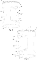
Fig. 1 is a front perspective view of an apparatus for handling a food product powder that includes a sealable container having an interior surface defining a volume in which the food product powder and a plurality of jet nozzles attached to the container and configured to feed air into the container. -
Fig. 2 is a side perspective view of one of the jet nozzles ofFig. 1 . -
Fig. 3 is a side perspective view of one of the jet nozzles ofFig. 1 showing a ceiling spray opening. -
Fig. 4 is another side perspective view of the jet nozzle ofFig. 1 showing the ceiling spray opening and a shaft spray opening. -
Fig. 5 is another side perspective view of the jet nozzle ofFig. 1 showing a side wall spray opening and a door spray opening. -
Fig. 6 is a side view of the jet nozzle ofFig. 1 showing the jet nozzle having a cylindrical body with cutouts on opposing sides of the jet nozzle. -
Fig. 7 is a cross-sectional view of the jet nozzle ofFig. 1 showing the ceiling spray opening, side wall spray opening, shaft spray opening, and door spray opening. -
Fig. 8 is a detailed cross-sectional view of the jet nozzle ofFig. 1 showing the shaft spray opening and the door spray opening. -
Fig. 9 is a front perspective view of the apparatus ofFig. 1 showing the spray patterns for the jet nozzle. -
Fig. 10 is a schematic drawing of a control system for the apparatus for handling a food product powder ofFig. 1 . -
Fig. 11 is a flow chart of a method for cleaning an apparatus for handling a food product powder including the apparatus ofFig. 1 . - Embodiments of the invention will now be described more fully hereinafter with reference to the accompanying drawings, in which some, but not all, embodiments of the invention are shown. The invention may be embodied in many different forms and should not be construed as limited to the embodiments set forth herein.
- With reference to
Fig. 1 , anexemplary apparatus 1 for handling a food product powder is shown. Theapparatus 1 includes asealable container 2 having aninterior surface 3 that defines avolume 4 in which the food product powder is handled, and apowder outlet 5. Theapparatus 1 may be oriented horizontally such that thepowder outlet 5 is arranged at a bottom of theapparatus 1. One ormore jet nozzles 6 are attached to thecontainer 2 and are configured to feed air into thecontainer 2 for removing residual food product powder from thecontainer 2 during a cleaning process that occurs after a bulk of the food product powder is removed from thecontainer 2. The bulk of the food product powder is removed from thecontainer 2 for further processing to produce a food product. Eachjet nozzle 6 is configured to direct the air towards different surfaces of theinterior surface 3 to remove the product powder from theinterior surface 3. The different surfaces include at least aceiling 7 and aside wall 8. After the product powder is removed from theinterior surface 3, the air and the removed product powder exit thecontainer 2 via thepowder outlet 5. - Handling the food product powder in the
container 2 may include stirring or mixing the food product powder. The food product powder may be any combination of milk powder, sugar, salt, or flour, or powder mixtures such as infant formula, cake and baking mixtures and similar food product powders. - The
apparatus 1 may be any apparatus that handles food product powder, such as a storage tank or mixers. In the illustrated example theapparatus 1 is a mixer. Theapparatus 1 has then arotatable stirring device 9, 10 for stirring or mixing the product powder mounted to aback wall 11 of thecontainer 2. Therotatable stirring device 9, 10 extends through thevolume 4 of thecontainer 2 when theapparatus 1 is assembled. Therotatable stirring device 9, 10 may include one or more rotatable shafts 9 that includemixing paddles 10. If more than one rotatable shaft 9 is provided, the rotatable shafts 9 may be arranged to counterrotate relative to each other. The shape of thecontainer 2 may be formed to accommodate rotation of the one or more rotatable shafts 9 and mixingpaddles 10. - The
interior surface 3 of thecontainer 2 is defined by theside wall 8, theceiling 7, theback wall 11, and a front wall arranged opposite theback wall 11. The front wall may be formed as apivotable door 12. Thedoor 12 may be attached to thecontainer 2 via hinges and handles 12a. Theceiling 7 extends from theside wall 8 to anotherside wall 13 arranged opposite to theside wall 8, and between theback wall 11 and thedoor 12. Theside walls ceiling 7 that is substantially planar and extends horizontally. - The
jet nozzles 6 are mounted to theceiling 7 of thecontainer 2 at a portion of thecontainer 2 at which theceiling 7 transitions to theside wall 8. Each of thejet nozzles 6 are positioned to direct a flow of air towards one or more of theceiling 7, theside wall 8, therotatable stirring device 9, 10, and thedoor 12. Anactuator 14 is connected to eachjet nozzle 6 and configured to actuate thejet nozzle 6 by displacing thejet nozzle 6 along its axis to push it into thevolume 4. - Any number of
jet nozzles 6 may be provided and the arrangement of thejet nozzles 6 is dependent on the shape of thecontainer 2. Between two and eight, or even more jet nozzles may be provided. Sixjet nozzles 6 may be provided including one set of threejet nozzles 6 being arranged on theceiling 7 proximate theside wall 8 and a second set of threejet nozzles 6 being arranged on theceiling 7 proximate theopposite side wall 13. The two sets ofjet nozzles 6 may be arranged tangentially relative to theceiling 7 and angled inwardly toward a center of thecontainer 2. Eachjet nozzle 6 in a same set may have a same orientation. Thejet nozzles 6 are arranged to ensure coverage of an entire area of theinterior surface 3, such that product powder may be removed from the entire surface area of theinterior surface 3. -
Fig. 2 shows astem 15 that is connected to theactuator 14 ofFig. 1 and to thejet nozzle 6. Thejet nozzle 6 positioned in ahousing 16 that is mounted to thecontainer 2 via aflange 17 which may be welded to thehousing 16. Thejet nozzle 6 includesinlets 19 that are fluidly connected between anair supply 20 andinlets 21 of thejet nozzle 6, which are shown inFig. 3 . Theair supply 20 may be a pressurized tank. Fourinlets 19 may be provided for thejet nozzle 6. Fewer than four or more than four inlets may be provided and the number of inlets may correspond to the number of spray openings formed on thejet nozzle 6. Eachinlet 19 may be connected to a respectivefluid supply line 22 and arespective control valve 23 such that the air supply to eachinlet 19 may be independently controlled. Thecontrol valves 23 may be solenoid valves or any other suitable control valve. -
Figs. 3 and4 show thejet nozzle 6 having acylindrical body 26 with afirst cutout 27 formed in afirst side 28 of thecylindrical body 26 and asecond cutout 29 formed in asecond side 30 of thecylindrical body 26 that is opposite thefirst side 28. Thecylindrical body 26 includes afirst end surface 31 that defines theinlets 21, as shown inFig. 3 and asecond end surface 32 that is opposite thefirst end surface 31, as shown inFig. 4 . When product powder is to be removed from theinterior surface 3 of the container, theactuator 14 pushes thejet nozzle 6 into thevolume 4 defined by thecontainer 2 and air is fed through thejet nozzle 6. When the product powder has been removed from theinterior surface 3, theactuator 14 retracts thejet nozzle 6 to a position in which thesecond end surface 32 is flush with theinterior surface 3 of thecontainer 2. - The
jet nozzle 6 includes aceiling spray opening 33 formed on thefirst side 28 of thejet nozzle 6 proximate thesecond end surface 32. When thejet nozzle 6 is attached to thecontainer 2 and thejet nozzle 6 is actuated by feeding air into it when inside thevolume 4, theceiling spray opening 33 is directed towards theceiling 7 of theinterior surface 3 to direct air towards theceiling 7 shown inFig. 1 . -
Fig. 5 shows thejet nozzle 6 including a sidewall spray opening 34 formed on thesecond side 30 of thejet nozzle 6 proximate thesecond end surface 32. When thejet nozzle 6 is actuated, the sidewall spray opening 34 is directed toward theside wall 8 to direct air toward theside wall 8 shown inFig. 1 . Theceiling spray opening 33 and the sidewall spray opening 34 are offset relative to a center of the respectivefirst side 28 andsecond side 30. Theceiling spray opening 33 and the sidewall spray opening 34 are offset in opposite radial directions such that theceiling spray opening 33 and the sidewall spray opening 34 are positioned opposite relative to each other on thecylindrical body 26. - As shown in
Fig. 4 , thejet nozzle 6 may also include ashaft spray opening 35 that is directed downwardly toward the rotatable stirring device 9, 10 (shown inFig. 1 ). Theshaft spray opening 35 is configured to provide a fan-shaped spray pattern and may be formed on thefirst side 28 of thejet nozzle 6 above theceiling spray opening 33. As shown inFig. 5 , thejet nozzle 6 may include adoor spray opening 36 that is directed towards thedoor 12 of the container 2 (shown inFig. 1 ). Thedoor spray opening 36 is inclined relative to a longitudinal axis L of thecylindrical body 26 and may be formed on thesecond side 30 of thejet nozzle 6 above the sidewall spray opening 34. - Advantageously, the
spray openings cylindrical body 26 of thejet nozzle 6 such that onejet nozzle 6 is able to direct air at different surfaces of the interior of thecontainer 2. Each of theceiling spray opening 33, the sidewall spray opening 34, theshaft spray opening 35, and thedoor spray opening 36 may be configured to provide different flow rates and different flow patterns. - In operation, when the
stem 15 shown inFig. 2 is actuated to push thejet nozzle 6 into thevolume 4 of thecontainer 2, thejet nozzle 6 is displaced relative to thehousing 16 that is secured to thecontainer 2. Thejet nozzle 6 then extends out of thehousing 16 and into thevolume 4 of thecontainer 2 to enable passage of air from theair supply 20 through thejet nozzle 6 into thecontainer 2. Thejet nozzle 6 may be displaced to a position in which theceiling spray opening 33 and the sidewall spray opening 34 are spaced between 50 and 60 millimeters from theinterior surface 3 of thecontainer 2. When thejet nozzle 6 is retracted by thestem 15, thejet nozzle 6 is moved back into thehousing 16 such that thehousing 16 blocks thespray openings -
Fig. 6 shows each of thefirst cutout 27 and thesecond cutout 29 including an upwardly directly directedsurface surface side surface surface surface side surface surfaces surfaces side surface surface surface side surface surfaces - As shown in
Fig. 4 , theceiling spray opening 33 may be formed on theside surface 41 of thefirst side 28 of thejet nozzle 6 proximate the upwardly directedsurface 37 of thefirst side 28. Theceiling spray opening 33 may be formed to be offset relative to the center of theside surface 41. Theshaft spray opening 35 may be formed on the downwardly directedsurface 39 of thefirst side 28 of thejet nozzle 6. Theshaft spray opening 35 may be centered or nearly centered on the downwardly directedsurface 39. - As shown in
Fig. 5 , the sidewall spray opening 34 may be formed on theside surface 42 of thesecond side 30 proximate the upwardly directedsurface 38 of thesecond side 30. The sidewall spray opening 34 may be formed to be offset relative to the center of theside surface 42. Thedoor spray opening 36 may be formed on the downwardly directedsurface 40 of thesecond side 30 of thejet nozzle 6. Thedoor spray opening 36 may be centered or nearly centered on the downwardly directedsurface 40. Other configurations of theceiling spray opening 33, the sidewall spray opening 34, theshaft spray opening 35, and thedoor spray opening 36 may be possible. -
Fig. 7 shows a cross-sectional view of thecylindrical body 26 including theceiling spray opening 33, the sidewall spray opening 34, theshaft spray opening 35, and thedoor spray opening 36. Each of thedoor spray opening 36, theceiling spray opening 33, the sidewall spray opening 34, and theshaft spray opening 35 is fluidly connected to a corresponding one of theinlets inlets door spray opening 36, theceiling spray opening 33, the sidewall spray opening 34, and theshaft spray opening 35, respectively. - The
ceiling spray opening 33 may include a plurality of openings that are arranged proximate each other and directed in different directions. Theceiling spray openings 33 are defined by cylindrical fluid passages that extend from afluid passage 33a that is connected to thefluid inlet 21a and extends parallel to the longitudinal axis L. The cylindrical fluid passages of theceiling spray openings 33 extend through thecylindrical body 26 of thejet nozzle 6 to theside surface 41. Between three and seven openings may be provided. Five openings may be provided. Each opening of theceiling spray openings 33 may be angled at a different angle µ relative to the longitudinal axis L and theceiling spray openings 33 are angled downwardly. A mean angle µ for the set ofceiling spray openings 33 may be approximately 80 degrees, such that some of theceiling spray openings 33 may be angled relative to the longitudinal axis L at angles that are larger than the mean angle µ and some of theceiling spray openings 33 may be angled at angles that are smaller than the mean angle µ. - The side
wall spray opening 34 may also include a plurality of openings that are arranged proximate each other directed in different directions. The sidewall spray openings 34 are defined by cylindrical fluid passages that extend from afluid passage 34a that is connected to thefluid inlet 21b and extends parallel to the longitudinal axis L. The cylindrical fluid passages of the sidewall spray openings 34 extend through thecylindrical body 26 of thejet nozzle 6 to theside surface 42. Between three and seven openings may be provided. Five openings may be provided. Each opening of theceiling spray openings 33 may be angled at a different angle ω relative to the longitudinal axis L and the sidewall spray openings 34 are angled downwardly. A mean angle µ for the set ofceiling spray openings 33 may be approximately 80 degrees, such that some of the sidewall spray openings 34 may be angled relative to the longitudinal axis L at angles that are larger than the mean angle ω and some of the sidewall spray openings 34 may be angled at angles that are smaller than the mean angle ω. -
Fig. 8 shows a detailed cross-sectional view of theshaft spray opening 35 and thedoor spray opening 36. Anunderside slot 43 of thedoor spray opening 36 extends along the downwardly directedsurface 40 of thesecond side 30 and aside slot 44 of thedoor spray opening 36 extends from theunderside slot 43 upwardly toward theinlet 21. Aflat body 45 of thedoor spray opening 36 defines theunderside slot 43 and theside slot 44 and extends through thecylindrical body 26 to theinlet 21. The widths of theunderside slot 43 and theside slot 44 may be uniform along the length of each of theunderside slot 43 and theside slot 44. Theflat body 45 may be inclined relative to the longitudinal axis L of the jet nozzle 6 (shown inFig. 5 ) by an angle that is between 10 and 40 degrees. - The
shaft spray opening 35 is defined by a truncated triangular body that extends from anotherinlet 46 of thejet nozzle 6 through thecylindrical body 26 to the downwardly directedsurface 39 of the second side. The truncated triangular shape is configured to provide a fan-shaped spray pattern outwardly from theshaft spray opening 35. In contrast to thedoor spray opening 36 which includes theside slot 44, theshaft spray opening 35 may have asingle underside slot 47 that extends along the downwardly directedsurface 39. -
Fig. 9 shows the different spray patterns provided by theceiling spray opening 33, the sidewall spray opening 34, theshaft spray opening 35, and thedoor spray opening 36 of thejet nozzle 6. The different spray patterns are directed toward different surfaces of the interior of thecontainer 2 to direct air at the surfaces during the cleaning operation for thepowder handling apparatus 1 shown inFig. 1 . Thefirst spray pattern 48 is provided by theceiling spray opening 33 and is directed toward theceiling 7. Thesecond spray pattern 49 is provided by the sidewall spray opening 34 and is directed toward theside wall 8. Thethird spray pattern 50 is directed toward the rotatable shaft 9 of therotatable stirring device 9, 10. Thefourth spray pattern 51 is provided by thedoor spray opening 36 and is directed toward thedoor 12. As shown inFig. 9 , eachspray pattern -
Fig. 10 shows anexemplary control system 52 for theapparatus 1. The cleaning process may be automated using thecontrol system 52 which includes aprocessor 53 that is communicatively coupled with thecontrol valves 23 and theactuators 14 for activation of thejet nozzles 6. Theprocessor 53 may include any suitable processors and electronic control mechanisms, such as, for example, a central processing unit (CPU), a microprocessor, control circuitry, and the like. Theair supply 20 may include a compressor and thecontrol system 52 may control the compressor to feed the air to thesupply lines 22 at a predetermined flow rate, e.g. a flow rate that is between 40 and 200 Nm3/h. Thecontrol system 52 may be used to maintain constant pressure in thesupply lines 22 for theinlets Figs. 2 and 3 . - The
control system 52 may also be used to vary the air flow through thejet nozzles 6 to temporarily increase the air flow through thejet nozzles 6. Thecontrol system 52 may be used to control thedifferent control valves 23 and vary the air flow through each of thesupply lines 22 which correspond to one of thespray openings jet nozzle 6. The flowrates at a gauge pressure of 5 barG for theceiling spray opening 33, the sidewall spray opening 34, theshaft spray opening 35, and thedoor spray opening 36 may be 70 Nm3/h, 70 Nm3/h, 100 Nm3/h, and 100 Nm3/h, respectively. Any predetermined sequence of air flow in thecontainer 2 may be provided using thecontrol system 52. Pulsated air flow, alternating air flow speeds, and different flow rates fordifferent jet nozzles 6 or theinlets 21 of thejet nozzles 6 may be provided. - The
processor 53 may be configured to control theactuator 14 shown inFig. 1 to push thejet nozzle 6 into thevolume 4 of thecontainer 2 when product powder is to be removed from theinterior surface 3 and retract thejet nozzle 6 when the product powder has been removed from theinterior surface 3. In operation, thecontrol valves 23 may be opened after thejet nozzles 6 are pushed into thevolume 4 of thecontainer 2 to enable air flow through the spray openings of thejet nozzles 6 into thecontainer 2. Avacuum pump 55 may also be controlled by theprocessor 53 and fluidly connected to thecontainer 2 for creating a suction effect that draws the air and the powder out of thepowder outlet 5 of thecontainer 2 shown inFig. 1 . Thevacuum pump 55 may be operable independently from thejet nozzles 6. Thecontainer 2 may be enclosed such that air may only exit through thepowder outlet 5. -
Fig. 11 shows amethod 56 for cleaning an apparatus for handling a food product powder is shown. Theapparatus 1 shown inFig. 1 and thecontrol system 52 shown inFig. 10 may be used to perform themethod 56. Themethod 56 includes astep 57 of feeding air into thecontainer 2 using thejet nozzles 6 that are attached to thecontainer 2. The air is directed by thejet nozzles 6 towards theinterior surface 3 to remove product powder from theinterior surface 3.Step 58 of themethod 56 includes directing air towards theceiling 7 of theinterior surface 3 using theceiling spray opening 33 formed on thefirst side 28 of thejet nozzle 6, and towards theside wall 8 of theinterior surface 3 using the sidewall spray opening 34 formed on thesecond side 30 of thejet nozzle 6 opposite thefirst side 28.Step 59 includes letting air out from thecontainer 2, such that air and the removed product powder may flow out of thecontainer 2 via thepowder outlet 5. - The apparatus for handling a food product powder including the jet nozzles is advantageous in providing more efficient cleaning of the apparatus. The jet nozzles in the nozzle arrangement are configured to direct a flow of air at multiple surfaces of the interior surface of the sealable container to remove the residual product powder from the interior surface. The removed product powder and the air may flow out of the container via the powder outlet and a vacuum pump, such that the manual cleaning process for the apparatus may be less intensive or eliminated. In addition to providing a more efficient cleaning process, using the nozzle arrangement advantageously enables a more sanitary cleaning process due to the container being able to remain sealed during the cleaning process.
- From the description above follows that, although various embodiments of the invention have been described and shown, the invention is not restricted thereto, but may also be embodied in other ways within the scope of the subject-matter defined in the following claims.
Claims (14)
- An apparatus (1) for handling a food product powder, the apparatus (1) comprisinga sealable container (2) having an interior surface (3) defining a volume (4) in which the food product powder is handled, and a powder outlet (5), anda jet nozzle (6) that is attached to the sealable container (2) and configured to feed air into the sealable container (2) and direct the air towards the interior surface (3) to remove product powder from the interior surface (3), such that the air and the removed product powder may flow out of the sealable container (2) via the powder outlet (5), characterized bythe jet nozzle (6) comprising a ceiling spray opening (33) formed on a first side (28) of the jet nozzle (6) and directed towards a ceiling (7) of the interior surface (3), and a side wall spray opening (34) formed on a second side (30) of the jet nozzle (6) opposite the first side (28) and directed towards a side wall (8) of the interior surface (3).
- The apparatus (1) according to claim 1, wherein the apparatus (1) is a mixing apparatus (1) that comprises a rotatable stirring device (9, 10) for the food product powder, wherein the jet nozzle (6) includes a shaft spray opening (35) directed towards the rotatable stirring device (9, 10).
- The apparatus (1) according to claim 2, wherein the shaft spray opening (35) is configured to provide a fan-shaped spray pattern.
- The apparatus (1) according to claim 2 or 3, wherein the jet nozzle (6) comprises a door spray opening (36) directed towards a door (11) of the sealable container (2).
- The apparatus (1) according to claim 4, wherein the door spray opening (36) is inclined relative to a longitudinal axis (L) of the jet nozzle (6).
- The apparatus (1) according to any preceding claim, wherein the jet nozzle (6) comprises a cylindrical body (26) that has a first cutout (27) in the first side (28) of the cylindrical body (26) and a second cutout (29) in the second side (30) of the cylindrical body (26) that is opposite the first side (28).
- The apparatus (1) according to claim 6, wherein each of the first cutout (27) and the second cutout (29) comprises, respectively, an upwardly directed surface (37, 38), a downwardly directed surface (39, 40) and a side surface (41, 42) that extends between the upwardly and downwardly directed surfaces (37, 38, 39, 40).
- The apparatus (1) according to claim 7, wherein the ceiling spray opening (33) is formed in the side surface (41) of the first side (28) proximate the upwardly directed surface (37) of the first side (28), and the side wall spray opening (34) is formed on the side surface (42) of the second side (30) proximate the upwardly directed surface (38) of the second side (30).
- The apparatus (1) according to claim 7 or 8, wherein the shaft spray opening (35) is formed on the downwardly directed surface (39) of the first side (28), and wherein the door spray opening (36) is formed on the downwardly directed surface (40) of the second side (30).
- The apparatus (1) according to any one of claims 7-9, wherein the upwardly directed surface (37, 38) is angled relative to the side surface (41, 42) at an angle (θ) that is greater than an angle (a) at which the downwardly directed surface (39, 40) is angled relative to the side surface (41, 42).
- The apparatus (1) according to any preceding claim, comprising an actuator (14) configured topush the jet nozzle (6) into the volume (4) defined by the sealable container (2), when product powder shall be removed from the interior surface (3), andretract the jet nozzle (6) to a position where an end surface (32) of the jet nozzle (6) is flush with the interior surface (3) of the sealable container (2), when product powder has been removed from the interior surface (3).
- The apparatus (1) according to any preceding claim, wherein the jet nozzle (6) comprises at least two inlets (21) that are each fluidly connected to an air supply (20) via separate fluid supply lines (22), each of the two inlets (21) being arranged to feed air to a respective one of the ceiling spray opening (33) and the side wall spray opening (34).
- The apparatus (1) according to any preceding claim, wherein the ceiling spray opening (33) includes a plurality of ceiling spray openings directed in different directions relative to a longitudinal axis (L) of the jet nozzle (6), and wherein the side wall spray opening (34) includes a plurality of side wall spray openings directed in different directions relative to the longitudinal axis (L) of the jet nozzle (6).
- A method (56) for cleaning an apparatus (1) for handling a food product powder, the apparatus (1) comprising a sealable container (2) having an interior surface (3) defining a volume (4) in which the food product powder is handled, and a powder outlet (5), the method (56) comprisingfeeding (57) air into the sealable container (2) using a jet nozzle (6) that is attached to the sealable container (2), wherein the air is directed by the jet nozzle (6) towards the interior surface (3) to remove product powder from the interior surface (3),directing (58) air towards a ceiling (7) of the interior surface (3) using a ceiling spray opening (33) formed on a first side (28) of the jet nozzle (6), and towards a side wall (8) of the interior surface (3) using a side wall spray opening (34) formed on a second side (30) of the jet nozzle (6) opposite the first side (28), andletting (59) air out from the sealable container (2), such that air and the removed product powder may flow out of the sealable container (2) via the powder outlet (5).
Applications Claiming Priority (1)
| Application Number | Priority Date | Filing Date | Title |
|---|---|---|---|
| EP20216366 | 2020-12-22 |
Publications (2)
| Publication Number | Publication Date |
|---|---|
| EP4019153A1 true EP4019153A1 (en) | 2022-06-29 |
| EP4019153B1 EP4019153B1 (en) | 2025-08-27 |
Family
ID=73856741
Family Applications (1)
| Application Number | Title | Priority Date | Filing Date |
|---|---|---|---|
| EP21215934.7A Active EP4019153B1 (en) | 2020-12-22 | 2021-12-20 | Jet nozzle for powder handling apparatus |
Country Status (5)
| Country | Link |
|---|---|
| US (1) | US20240033699A1 (en) |
| EP (1) | EP4019153B1 (en) |
| CN (1) | CN116635166B (en) |
| AU (1) | AU2021404993A1 (en) |
| WO (1) | WO2022136240A1 (en) |
Citations (8)
| Publication number | Priority date | Publication date | Assignee | Title |
|---|---|---|---|---|
| US3138167A (en) * | 1963-06-18 | 1964-06-23 | Sprout Waldron & Co Inc | Mixer for feeds and the like |
| EP0358120A2 (en) * | 1988-09-07 | 1990-03-14 | Werner Lüber | Mixing plant for granulated products especially core sand |
| WO2009083634A1 (en) * | 2007-12-27 | 2009-07-09 | Ari Koski | Method for cleaning of a powder coating housing and a powder coating housing |
| US20100186775A1 (en) * | 2009-01-29 | 2010-07-29 | Madsen Ole T | Rotating cleaning system |
| EP2777831A1 (en) * | 2013-03-14 | 2014-09-17 | m-tec mathis technik gmbh | Method for cleaning a bulk material mixer and bulk material mixer with mixing container to be cleaned |
| DE102013006822A1 (en) * | 2013-04-22 | 2014-10-23 | Hermann Linder | Cleaning arrangement with a material storage container for the conveyor and cleaning methods |
| EP3075459A1 (en) * | 2015-03-30 | 2016-10-05 | Alfa Laval Corporate AB | Fluid ejection apparatus |
| CN108940529A (en) * | 2018-06-27 | 2018-12-07 | 郑州郑先医药科技有限公司 | A kind of efficient raw material grinding device of pharmaceutical production processing |
Family Cites Families (19)
| Publication number | Priority date | Publication date | Assignee | Title |
|---|---|---|---|---|
| US240831A (en) * | 1881-05-03 | maofarlane | ||
| GB142534A (en) * | 1919-01-31 | 1920-04-30 | Harold Maxwell Lefroy | Improvements in powder distributors |
| US2563130A (en) * | 1948-11-30 | 1951-08-07 | Emhart Mfg Co | Apparatus for tempering glassware |
| US3142306A (en) * | 1963-01-07 | 1964-07-28 | Purex Corp Ltd | Spray nozzle |
| US3856570A (en) * | 1972-10-11 | 1974-12-24 | Shell Oil Co | Method and apparatus for cleaning the interior of industrial vessels by using rotating nozzle heads |
| US3833010A (en) * | 1973-03-20 | 1974-09-03 | Shell Oil Co | Method for cleaning gasoline storage tanks |
| US4479612A (en) * | 1982-09-28 | 1984-10-30 | Umbach Newell L | Retractable glycol spray nozzle |
| DE3604694A1 (en) * | 1986-02-14 | 1987-08-20 | Bayer Ag | Ointment kettle for the manufacture of pharmaceutical or cosmetic suspensions |
| GB2211434A (en) * | 1987-10-27 | 1989-07-05 | Netzsch Mastermix Ltd | Cleaning mixing vessel |
| DE3800379A1 (en) * | 1988-01-08 | 1989-07-20 | Boehringer Mannheim Gmbh | DEVICE FOR WASHING THE INSIDE SURFACE OF A REACTION TUBE AND / OR THE EXTERIOR SURFACE OF A TESTED BALL |
| US4859249A (en) * | 1988-03-14 | 1989-08-22 | E. I. Du Pont De Nemours And Company | Process for cleaning enclosed vessels |
| US5222512A (en) * | 1988-06-13 | 1993-06-29 | Tenneco Canada Inc. | Sparger system for discharge of bulk material from hopper cars |
| US5613510A (en) * | 1995-10-10 | 1997-03-25 | Proctor; Ronald E. | Tank internal surface cleaning system |
| US5865536A (en) * | 1995-11-29 | 1999-02-02 | Richard Frisse Gmbh | Method and conching machine for introducing a substance into it |
| JP2814373B2 (en) * | 1996-12-06 | 1998-10-22 | 株式会社マンヨー食品 | Food surface coating method and apparatus |
| US6213134B1 (en) * | 1999-02-26 | 2001-04-10 | Econo Clean, Incorporated | Interior tank car cleaning apparatus |
| AT6709U1 (en) * | 2003-04-03 | 2004-03-25 | Schauer Maschinenfabrik Gmbh | METHOD FOR CLEANING THE INTERNAL CONTAINERS FOR LIQUID FEED IN FEEDING SYSTEMS AND DEVICE FOR IMPLEMENTING THE METHOD |
| JP5928952B2 (en) * | 2012-10-31 | 2016-06-01 | 株式会社栗本鐵工所 | Pipe inner surface coating equipment |
| EP3837986B1 (en) * | 2019-12-20 | 2025-06-18 | Tetra Laval Holdings & Finance S.A. | Nozzle arrangement for a powder handling apparatus |
-
2021
- 2021-12-20 US US18/258,645 patent/US20240033699A1/en active Pending
- 2021-12-20 WO PCT/EP2021/086739 patent/WO2022136240A1/en not_active Ceased
- 2021-12-20 CN CN202180085698.XA patent/CN116635166B/en active Active
- 2021-12-20 AU AU2021404993A patent/AU2021404993A1/en active Pending
- 2021-12-20 EP EP21215934.7A patent/EP4019153B1/en active Active
Patent Citations (8)
| Publication number | Priority date | Publication date | Assignee | Title |
|---|---|---|---|---|
| US3138167A (en) * | 1963-06-18 | 1964-06-23 | Sprout Waldron & Co Inc | Mixer for feeds and the like |
| EP0358120A2 (en) * | 1988-09-07 | 1990-03-14 | Werner Lüber | Mixing plant for granulated products especially core sand |
| WO2009083634A1 (en) * | 2007-12-27 | 2009-07-09 | Ari Koski | Method for cleaning of a powder coating housing and a powder coating housing |
| US20100186775A1 (en) * | 2009-01-29 | 2010-07-29 | Madsen Ole T | Rotating cleaning system |
| EP2777831A1 (en) * | 2013-03-14 | 2014-09-17 | m-tec mathis technik gmbh | Method for cleaning a bulk material mixer and bulk material mixer with mixing container to be cleaned |
| DE102013006822A1 (en) * | 2013-04-22 | 2014-10-23 | Hermann Linder | Cleaning arrangement with a material storage container for the conveyor and cleaning methods |
| EP3075459A1 (en) * | 2015-03-30 | 2016-10-05 | Alfa Laval Corporate AB | Fluid ejection apparatus |
| CN108940529A (en) * | 2018-06-27 | 2018-12-07 | 郑州郑先医药科技有限公司 | A kind of efficient raw material grinding device of pharmaceutical production processing |
Also Published As
| Publication number | Publication date |
|---|---|
| CN116635166A (en) | 2023-08-22 |
| US20240033699A1 (en) | 2024-02-01 |
| WO2022136240A1 (en) | 2022-06-30 |
| AU2021404993A9 (en) | 2024-06-20 |
| CN116635166B (en) | 2026-01-02 |
| EP4019153B1 (en) | 2025-08-27 |
| AU2021404993A1 (en) | 2023-07-06 |
Similar Documents
| Publication | Publication Date | Title |
|---|---|---|
| EP3305090A1 (en) | Machine for making liquid or semi-liquid products | |
| CN106234750B (en) | Ice cream dispensing device and machine for making ice cream | |
| US20110085407A1 (en) | Kneading device | |
| CN107912597A (en) | For making the method for liquid or semi liquid state product and implementing the machine of this method | |
| WO2018020006A1 (en) | A system and a method for supplying powder and mixing the powder into a liquid | |
| CN112367845A (en) | Mixing device | |
| CN106714638B (en) | Shear Blade Assembly for Blender | |
| US12274992B2 (en) | Stirring apparatus for boiled noodles | |
| US12389921B2 (en) | Nozzle arrangement for a powder handling apparatus | |
| CN110770519A (en) | Food processor with integrated blending process | |
| EP4019153B1 (en) | Jet nozzle for powder handling apparatus | |
| CN106061279B (en) | Apparatus for producing and/or mixing a confectionery mass and method for cleaning an apparatus for producing and/or mixing a confectionery mass | |
| EP0776829A1 (en) | Powder filling apparatus | |
| TW202031347A (en) | Manufacturing apparatus and method | |
| US7717612B2 (en) | Device for continuously mixing a food dough provided with two types of superimposed mixing tools and a side discharge | |
| KR20260017934A (en) | Mold Formed Food Manufacturing Apparatus with Detachable Valved Pipe | |
| CN220589654U (en) | A stirring mixing device for jam production | |
| EP3827892B1 (en) | A food product processing system and a method for collecting powder | |
| CN215422721U (en) | Automatic pickling machine of kumquat pulp | |
| CN212139109U (en) | Novel automatic flour-mixing machine | |
| US20150208670A1 (en) | Device for mixing and/or kneading food products | |
| KR890003999B1 (en) | Apparatus for making fermented soybean paste | |
| CN216704233U (en) | Liquid preparation device with cleaning function | |
| CN217662785U (en) | Cream processingequipment is used in cake production | |
| JP3784557B2 (en) | Steaming machine |
Legal Events
| Date | Code | Title | Description |
|---|---|---|---|
| PUAI | Public reference made under article 153(3) epc to a published international application that has entered the european phase |
Free format text: ORIGINAL CODE: 0009012 |
|
| STAA | Information on the status of an ep patent application or granted ep patent |
Free format text: STATUS: THE APPLICATION HAS BEEN PUBLISHED |
|
| AK | Designated contracting states |
Kind code of ref document: A1 Designated state(s): AL AT BE BG CH CY CZ DE DK EE ES FI FR GB GR HR HU IE IS IT LI LT LU LV MC MK MT NL NO PL PT RO RS SE SI SK SM TR |
|
| STAA | Information on the status of an ep patent application or granted ep patent |
Free format text: STATUS: REQUEST FOR EXAMINATION WAS MADE |
|
| 17P | Request for examination filed |
Effective date: 20230102 |
|
| RBV | Designated contracting states (corrected) |
Designated state(s): AL AT BE BG CH CY CZ DE DK EE ES FI FR GB GR HR HU IE IS IT LI LT LU LV MC MK MT NL NO PL PT RO RS SE SI SK SM TR |
|
| STAA | Information on the status of an ep patent application or granted ep patent |
Free format text: STATUS: EXAMINATION IS IN PROGRESS |
|
| 17Q | First examination report despatched |
Effective date: 20230301 |
|
| GRAP | Despatch of communication of intention to grant a patent |
Free format text: ORIGINAL CODE: EPIDOSNIGR1 |
|
| STAA | Information on the status of an ep patent application or granted ep patent |
Free format text: STATUS: GRANT OF PATENT IS INTENDED |
|
| INTG | Intention to grant announced |
Effective date: 20250324 |
|
| GRAS | Grant fee paid |
Free format text: ORIGINAL CODE: EPIDOSNIGR3 |
|
| GRAA | (expected) grant |
Free format text: ORIGINAL CODE: 0009210 |
|
| STAA | Information on the status of an ep patent application or granted ep patent |
Free format text: STATUS: THE PATENT HAS BEEN GRANTED |
|
| AK | Designated contracting states |
Kind code of ref document: B1 Designated state(s): AL AT BE BG CH CY CZ DE DK EE ES FI FR GB GR HR HU IE IS IT LI LT LU LV MC MK MT NL NO PL PT RO RS SE SI SK SM TR |
|
| REG | Reference to a national code |
Ref country code: CH Ref legal event code: EP |
|
| REG | Reference to a national code |
Ref country code: DE Ref legal event code: R096 Ref document number: 602021037073 Country of ref document: DE |
|
| REG | Reference to a national code |
Ref country code: IE Ref legal event code: FG4D |
|
| REG | Reference to a national code |
Ref country code: NL Ref legal event code: FP |
|
| PG25 | Lapsed in a contracting state [announced via postgrant information from national office to epo] |
Ref country code: IS Free format text: LAPSE BECAUSE OF FAILURE TO SUBMIT A TRANSLATION OF THE DESCRIPTION OR TO PAY THE FEE WITHIN THE PRESCRIBED TIME-LIMIT Effective date: 20251227 |
|
| PG25 | Lapsed in a contracting state [announced via postgrant information from national office to epo] |
Ref country code: NO Free format text: LAPSE BECAUSE OF FAILURE TO SUBMIT A TRANSLATION OF THE DESCRIPTION OR TO PAY THE FEE WITHIN THE PRESCRIBED TIME-LIMIT Effective date: 20251127 |
|
| REG | Reference to a national code |
Ref country code: LT Ref legal event code: MG9D |
|
| PG25 | Lapsed in a contracting state [announced via postgrant information from national office to epo] |
Ref country code: PT Free format text: LAPSE BECAUSE OF FAILURE TO SUBMIT A TRANSLATION OF THE DESCRIPTION OR TO PAY THE FEE WITHIN THE PRESCRIBED TIME-LIMIT Effective date: 20251229 |
|
| PG25 | Lapsed in a contracting state [announced via postgrant information from national office to epo] |
Ref country code: FI Free format text: LAPSE BECAUSE OF FAILURE TO SUBMIT A TRANSLATION OF THE DESCRIPTION OR TO PAY THE FEE WITHIN THE PRESCRIBED TIME-LIMIT Effective date: 20250827 |
|
| PG25 | Lapsed in a contracting state [announced via postgrant information from national office to epo] |
Ref country code: HR Free format text: LAPSE BECAUSE OF FAILURE TO SUBMIT A TRANSLATION OF THE DESCRIPTION OR TO PAY THE FEE WITHIN THE PRESCRIBED TIME-LIMIT Effective date: 20250827 |
|
| PGFP | Annual fee paid to national office [announced via postgrant information from national office to epo] |
Ref country code: NL Payment date: 20251222 Year of fee payment: 5 |
|
| PG25 | Lapsed in a contracting state [announced via postgrant information from national office to epo] |
Ref country code: GR Free format text: LAPSE BECAUSE OF FAILURE TO SUBMIT A TRANSLATION OF THE DESCRIPTION OR TO PAY THE FEE WITHIN THE PRESCRIBED TIME-LIMIT Effective date: 20251128 |
|
| PG25 | Lapsed in a contracting state [announced via postgrant information from national office to epo] |
Ref country code: SE Free format text: LAPSE BECAUSE OF FAILURE TO SUBMIT A TRANSLATION OF THE DESCRIPTION OR TO PAY THE FEE WITHIN THE PRESCRIBED TIME-LIMIT Effective date: 20250827 |
|
| PG25 | Lapsed in a contracting state [announced via postgrant information from national office to epo] |
Ref country code: LV Free format text: LAPSE BECAUSE OF FAILURE TO SUBMIT A TRANSLATION OF THE DESCRIPTION OR TO PAY THE FEE WITHIN THE PRESCRIBED TIME-LIMIT Effective date: 20250827 |
|
| PG25 | Lapsed in a contracting state [announced via postgrant information from national office to epo] |
Ref country code: PL Free format text: LAPSE BECAUSE OF FAILURE TO SUBMIT A TRANSLATION OF THE DESCRIPTION OR TO PAY THE FEE WITHIN THE PRESCRIBED TIME-LIMIT Effective date: 20250827 Ref country code: BG Free format text: LAPSE BECAUSE OF FAILURE TO SUBMIT A TRANSLATION OF THE DESCRIPTION OR TO PAY THE FEE WITHIN THE PRESCRIBED TIME-LIMIT Effective date: 20250827 |
|
| PG25 | Lapsed in a contracting state [announced via postgrant information from national office to epo] |
Ref country code: RS Free format text: LAPSE BECAUSE OF FAILURE TO SUBMIT A TRANSLATION OF THE DESCRIPTION OR TO PAY THE FEE WITHIN THE PRESCRIBED TIME-LIMIT Effective date: 20251127 |
|
| PG25 | Lapsed in a contracting state [announced via postgrant information from national office to epo] |
Ref country code: ES Free format text: LAPSE BECAUSE OF FAILURE TO SUBMIT A TRANSLATION OF THE DESCRIPTION OR TO PAY THE FEE WITHIN THE PRESCRIBED TIME-LIMIT Effective date: 20250827 |
|
| REG | Reference to a national code |
Ref country code: AT Ref legal event code: MK05 Ref document number: 1829424 Country of ref document: AT Kind code of ref document: T Effective date: 20250827 |
|
| PG25 | Lapsed in a contracting state [announced via postgrant information from national office to epo] |
Ref country code: RO Free format text: LAPSE BECAUSE OF FAILURE TO SUBMIT A TRANSLATION OF THE DESCRIPTION OR TO PAY THE FEE WITHIN THE PRESCRIBED TIME-LIMIT Effective date: 20250827 |
|
| PG25 | Lapsed in a contracting state [announced via postgrant information from national office to epo] |
Ref country code: SM Free format text: LAPSE BECAUSE OF FAILURE TO SUBMIT A TRANSLATION OF THE DESCRIPTION OR TO PAY THE FEE WITHIN THE PRESCRIBED TIME-LIMIT Effective date: 20250827 |
|
| PG25 | Lapsed in a contracting state [announced via postgrant information from national office to epo] |
Ref country code: DK Free format text: LAPSE BECAUSE OF FAILURE TO SUBMIT A TRANSLATION OF THE DESCRIPTION OR TO PAY THE FEE WITHIN THE PRESCRIBED TIME-LIMIT Effective date: 20250827 |
|
| PGFP | Annual fee paid to national office [announced via postgrant information from national office to epo] |
Ref country code: DE Payment date: 20251229 Year of fee payment: 5 |
|
| PG25 | Lapsed in a contracting state [announced via postgrant information from national office to epo] |
Ref country code: AT Free format text: LAPSE BECAUSE OF FAILURE TO SUBMIT A TRANSLATION OF THE DESCRIPTION OR TO PAY THE FEE WITHIN THE PRESCRIBED TIME-LIMIT Effective date: 20250827 |
|
| PG25 | Lapsed in a contracting state [announced via postgrant information from national office to epo] |
Ref country code: IT Free format text: LAPSE BECAUSE OF FAILURE TO SUBMIT A TRANSLATION OF THE DESCRIPTION OR TO PAY THE FEE WITHIN THE PRESCRIBED TIME-LIMIT Effective date: 20250827 |
|
| PG25 | Lapsed in a contracting state [announced via postgrant information from national office to epo] |
Ref country code: CZ Free format text: LAPSE BECAUSE OF FAILURE TO SUBMIT A TRANSLATION OF THE DESCRIPTION OR TO PAY THE FEE WITHIN THE PRESCRIBED TIME-LIMIT Effective date: 20250827 |
|
| PG25 | Lapsed in a contracting state [announced via postgrant information from national office to epo] |
Ref country code: SK Free format text: LAPSE BECAUSE OF FAILURE TO SUBMIT A TRANSLATION OF THE DESCRIPTION OR TO PAY THE FEE WITHIN THE PRESCRIBED TIME-LIMIT Effective date: 20250827 Ref country code: EE Free format text: LAPSE BECAUSE OF FAILURE TO SUBMIT A TRANSLATION OF THE DESCRIPTION OR TO PAY THE FEE WITHIN THE PRESCRIBED TIME-LIMIT Effective date: 20250827 |