EP4019106A1 - Crystalliser, method for crystallising and use of the crystalliser in performing the method - Google Patents
Crystalliser, method for crystallising and use of the crystalliser in performing the method Download PDFInfo
- Publication number
- EP4019106A1 EP4019106A1 EP20216950.4A EP20216950A EP4019106A1 EP 4019106 A1 EP4019106 A1 EP 4019106A1 EP 20216950 A EP20216950 A EP 20216950A EP 4019106 A1 EP4019106 A1 EP 4019106A1
- Authority
- EP
- European Patent Office
- Prior art keywords
- crystalliser
- composition
- section
- outlet
- inlet
- Prior art date
- Legal status (The legal status is an assumption and is not a legal conclusion. Google has not performed a legal analysis and makes no representation as to the accuracy of the status listed.)
- Withdrawn
Links
- 238000000034 method Methods 0.000 title claims description 78
- 239000013078 crystal Substances 0.000 claims abstract description 186
- 239000000203 mixture Substances 0.000 claims abstract description 148
- 239000000110 cooling liquid Substances 0.000 claims abstract description 124
- 239000002002 slurry Substances 0.000 claims abstract description 103
- 239000007788 liquid Substances 0.000 claims abstract description 86
- 238000001816 cooling Methods 0.000 claims abstract description 56
- 239000007787 solid Substances 0.000 claims abstract description 51
- 238000002425 crystallisation Methods 0.000 claims description 46
- ZHJGWYRLJUCMRT-UHFFFAOYSA-N 5-[6-[(4-methylpiperazin-1-yl)methyl]benzimidazol-1-yl]-3-[1-[2-(trifluoromethyl)phenyl]ethoxy]thiophene-2-carboxamide Chemical compound C=1C=CC=C(C(F)(F)F)C=1C(C)OC(=C(S1)C(N)=O)C=C1N(C1=C2)C=NC1=CC=C2CN1CCN(C)CC1 ZHJGWYRLJUCMRT-UHFFFAOYSA-N 0.000 claims description 21
- 238000010438 heat treatment Methods 0.000 claims description 18
- 239000012530 fluid Substances 0.000 claims description 12
- 238000004891 communication Methods 0.000 claims description 11
- 230000029087 digestion Effects 0.000 claims description 10
- GRYLNZFGIOXLOG-UHFFFAOYSA-N Nitric acid Chemical compound O[N+]([O-])=O GRYLNZFGIOXLOG-UHFFFAOYSA-N 0.000 claims description 9
- 229910017604 nitric acid Inorganic materials 0.000 claims description 9
- 238000011144 upstream manufacturing Methods 0.000 claims description 9
- 239000002367 phosphate rock Substances 0.000 claims description 7
- NBIIXXVUZAFLBC-UHFFFAOYSA-N Phosphoric acid Chemical compound OP(O)(O)=O NBIIXXVUZAFLBC-UHFFFAOYSA-N 0.000 claims description 6
- 229910000147 aluminium phosphate Inorganic materials 0.000 claims description 3
- 239000007789 gas Substances 0.000 description 70
- 238000001704 evaporation Methods 0.000 description 17
- 238000000926 separation method Methods 0.000 description 15
- 230000008020 evaporation Effects 0.000 description 13
- 239000000243 solution Substances 0.000 description 12
- 238000005304 joining Methods 0.000 description 11
- 229910019142 PO4 Inorganic materials 0.000 description 9
- 239000002826 coolant Substances 0.000 description 9
- 230000006911 nucleation Effects 0.000 description 8
- 238000010899 nucleation Methods 0.000 description 8
- 230000008901 benefit Effects 0.000 description 7
- 230000000694 effects Effects 0.000 description 7
- 239000010452 phosphate Substances 0.000 description 7
- ATUOYWHBWRKTHZ-UHFFFAOYSA-N Propane Chemical compound CCC ATUOYWHBWRKTHZ-UHFFFAOYSA-N 0.000 description 6
- 238000004064 recycling Methods 0.000 description 6
- 239000012452 mother liquor Substances 0.000 description 5
- 239000000126 substance Substances 0.000 description 5
- GNFTZDOKVXKIBK-UHFFFAOYSA-N 3-(2-methoxyethoxy)benzohydrazide Chemical compound COCCOC1=CC=CC(C(=O)NN)=C1 GNFTZDOKVXKIBK-UHFFFAOYSA-N 0.000 description 4
- 238000004519 manufacturing process Methods 0.000 description 4
- IJDNQMDRQITEOD-UHFFFAOYSA-N n-butane Chemical compound CCCC IJDNQMDRQITEOD-UHFFFAOYSA-N 0.000 description 4
- 239000002245 particle Substances 0.000 description 4
- 230000015572 biosynthetic process Effects 0.000 description 3
- 239000001273 butane Substances 0.000 description 3
- 230000008025 crystallization Effects 0.000 description 3
- 238000002156 mixing Methods 0.000 description 3
- OFBQJSOFQDEBGM-UHFFFAOYSA-N n-pentane Natural products CCCCC OFBQJSOFQDEBGM-UHFFFAOYSA-N 0.000 description 3
- 239000001294 propane Substances 0.000 description 3
- XLYOFNOQVPJJNP-UHFFFAOYSA-N water Substances O XLYOFNOQVPJJNP-UHFFFAOYSA-N 0.000 description 3
- QGZKDVFQNNGYKY-UHFFFAOYSA-N Ammonia Chemical compound N QGZKDVFQNNGYKY-UHFFFAOYSA-N 0.000 description 2
- 238000004220 aggregation Methods 0.000 description 2
- 230000002776 aggregation Effects 0.000 description 2
- 238000013019 agitation Methods 0.000 description 2
- ZCCIPPOKBCJFDN-UHFFFAOYSA-N calcium nitrate Chemical compound [Ca+2].[O-][N+]([O-])=O.[O-][N+]([O-])=O ZCCIPPOKBCJFDN-UHFFFAOYSA-N 0.000 description 2
- 239000011248 coating agent Substances 0.000 description 2
- 150000001875 compounds Chemical group 0.000 description 2
- SQNZJJAZBFDUTD-UHFFFAOYSA-N durene Chemical compound CC1=CC(C)=C(C)C=C1C SQNZJJAZBFDUTD-UHFFFAOYSA-N 0.000 description 2
- 238000006386 neutralization reaction Methods 0.000 description 2
- 235000021317 phosphate Nutrition 0.000 description 2
- 150000003013 phosphoric acid derivatives Chemical class 0.000 description 2
- 159000000001 potassium salts Chemical class 0.000 description 2
- 229910002651 NO3 Inorganic materials 0.000 description 1
- NHNBFGGVMKEFGY-UHFFFAOYSA-N Nitrate Chemical compound [O-][N+]([O-])=O NHNBFGGVMKEFGY-UHFFFAOYSA-N 0.000 description 1
- YTAHJIFKAKIKAV-XNMGPUDCSA-N [(1R)-3-morpholin-4-yl-1-phenylpropyl] N-[(3S)-2-oxo-5-phenyl-1,3-dihydro-1,4-benzodiazepin-3-yl]carbamate Chemical compound O=C1[C@H](N=C(C2=C(N1)C=CC=C2)C1=CC=CC=C1)NC(O[C@H](CCN1CCOCC1)C1=CC=CC=C1)=O YTAHJIFKAKIKAV-XNMGPUDCSA-N 0.000 description 1
- 238000010521 absorption reaction Methods 0.000 description 1
- 239000000654 additive Substances 0.000 description 1
- 150000001335 aliphatic alkanes Chemical class 0.000 description 1
- 229910021529 ammonia Inorganic materials 0.000 description 1
- 239000007864 aqueous solution Substances 0.000 description 1
- 125000003118 aryl group Chemical group 0.000 description 1
- 230000001174 ascending effect Effects 0.000 description 1
- 238000009835 boiling Methods 0.000 description 1
- HOWJQLVNDUGZBI-UHFFFAOYSA-N butane;propane Chemical compound CCC.CCCC HOWJQLVNDUGZBI-UHFFFAOYSA-N 0.000 description 1
- 238000005119 centrifugation Methods 0.000 description 1
- 238000003889 chemical engineering Methods 0.000 description 1
- 238000000576 coating method Methods 0.000 description 1
- 230000006835 compression Effects 0.000 description 1
- 238000007906 compression Methods 0.000 description 1
- 238000011437 continuous method Methods 0.000 description 1
- 238000010924 continuous production Methods 0.000 description 1
- 230000008021 deposition Effects 0.000 description 1
- 238000010586 diagram Methods 0.000 description 1
- 238000002474 experimental method Methods 0.000 description 1
- 239000002360 explosive Substances 0.000 description 1
- 238000013213 extrapolation Methods 0.000 description 1
- 239000003337 fertilizer Substances 0.000 description 1
- 238000001914 filtration Methods 0.000 description 1
- 239000012467 final product Substances 0.000 description 1
- 230000008014 freezing Effects 0.000 description 1
- 238000007710 freezing Methods 0.000 description 1
- 150000008282 halocarbons Chemical class 0.000 description 1
- 239000004973 liquid crystal related substance Substances 0.000 description 1
- 239000006193 liquid solution Substances 0.000 description 1
- 229940082615 organic nitrates used in cardiac disease Drugs 0.000 description 1
- 230000000704 physical effect Effects 0.000 description 1
- 239000011148 porous material Substances 0.000 description 1
- 230000001376 precipitating effect Effects 0.000 description 1
- 238000001556 precipitation Methods 0.000 description 1
- 239000000047 product Substances 0.000 description 1
- 238000005086 pumping Methods 0.000 description 1
- 239000011435 rock Substances 0.000 description 1
- 229930195734 saturated hydrocarbon Natural products 0.000 description 1
- 239000002904 solvent Substances 0.000 description 1
- 238000003860 storage Methods 0.000 description 1
- 239000013526 supercooled liquid Substances 0.000 description 1
- 239000000725 suspension Substances 0.000 description 1
- 238000010792 warming Methods 0.000 description 1
Images



Classifications
-
- B—PERFORMING OPERATIONS; TRANSPORTING
- B01—PHYSICAL OR CHEMICAL PROCESSES OR APPARATUS IN GENERAL
- B01D—SEPARATION
- B01D9/00—Crystallisation
- B01D9/005—Selection of auxiliary, e.g. for control of crystallisation nuclei, of crystal growth, of adherence to walls; Arrangements for introduction thereof
-
- B—PERFORMING OPERATIONS; TRANSPORTING
- B01—PHYSICAL OR CHEMICAL PROCESSES OR APPARATUS IN GENERAL
- B01D—SEPARATION
- B01D9/00—Crystallisation
- B01D9/0004—Crystallisation cooling by heat exchange
- B01D9/0009—Crystallisation cooling by heat exchange by direct heat exchange with added cooling fluid
-
- B—PERFORMING OPERATIONS; TRANSPORTING
- B01—PHYSICAL OR CHEMICAL PROCESSES OR APPARATUS IN GENERAL
- B01D—SEPARATION
- B01D9/00—Crystallisation
- B01D9/0059—General arrangements of crystallisation plant, e.g. flow sheets
-
- C—CHEMISTRY; METALLURGY
- C01—INORGANIC CHEMISTRY
- C01F—COMPOUNDS OF THE METALS BERYLLIUM, MAGNESIUM, ALUMINIUM, CALCIUM, STRONTIUM, BARIUM, RADIUM, THORIUM, OR OF THE RARE-EARTH METALS
- C01F11/00—Compounds of calcium, strontium, or barium
- C01F11/36—Nitrates
- C01F11/44—Concentrating; Crystallisating; Dehydrating; Preventing the absorption of moisture or caking
-
- B—PERFORMING OPERATIONS; TRANSPORTING
- B01—PHYSICAL OR CHEMICAL PROCESSES OR APPARATUS IN GENERAL
- B01D—SEPARATION
- B01D9/00—Crystallisation
- B01D9/0036—Crystallisation on to a bed of product crystals; Seeding
Definitions
- the present disclosure relates to the field of crystalliser apparatuses. It further relates to the field of methods for crystallising and to the use of crystallisers for performing those methods.
- Crystallisation is the natural or artificial process by which a solid forms, where the atoms or molecules are highly organized into a structure known as a crystal. Some of the ways by which crystals form are precipitating from a solution, freezing, or more rarely deposition directly from a gas. Attributes of the resulting crystal depend largely on factors such as temperature, air pressure, and in the case of liquid crystals, time of fluid evaporation.
- Crystallisation occurs in two major steps. The first is nucleation, the appearance of a crystalline phase from either a supercooled liquid or a supersaturated solvent. The second step is known as crystal growth, which is the increase in the size of particles and leads to a crystal state. An important feature of this step is that loose particles form layers at the crystal's surface and lodge themselves into open inconsistencies such as pores, cracks or their equivalents.
- Crystallisation is also a chemical solid-liquid separation technique, in which mass transfer of a solute from the liquid solution to a pure solid crystalline phase occurs.
- crystallisation occurs in a crystalliser. Crystallisation is therefore related to precipitation, although the result is not an amorphous or disordered substance, but a crystal.
- a possibility to achieve crystallisation is to cool the solution from which crystals are to be formed. This cooling can be achieved through either direct or indirect heat transfer.
- indirect heat transfer a coolant and the solution to be cooled are circulated in separate closed chambers without direct physical contact, for example in a heat exchanger.
- direct heat transfer the coolant and the solution to be cooled are brought into direct physical contact, in a single compartment that is the crystallisation chamber of the crystalliser.
- GB932215 discloses a continuous process for the crystallisation of calcium nitrate tetrahydrate from the aqueous solutions obtained by decomposing rock phosphates with nitric acid, by cooling said solutions with an inert liquid having lower density than and immiscible with the solutions, said cooling liquid being introduced directly into said solutions to cool same to the crystallisation temperature of +10 to -25 °C, and heated and/or evaporated by the contact therewith so that the solutions are agitated and circulated by the ascending cooling liquid or by its vapours, characterised in that the cooling liquid is introduced dropwise at the bottom of a perpendicularly arranged cylindrical body place concentrically in the vessel in order to maintain the suspension of the growing crystals in a vertical circulation, the crystals when having grown mainly to a size of from 0.4 mm to 1.00 mm, sedimenting on the bottom of the vessel and being drawn off together with the mother liquor.
- the cooling of the crystallisation bath to the required crystallisation temperature of +10 to -25 °C and the transfer of the heat of crystallisation is attained either by evaporating the liquid within the crystallisation bath or on its surface, or in warming the frigorific liquid.
- the evaporated frigorific substance or the warmed frigorific liquid with a temperature of -5 to +10 °C is drained off at the top part of the crystalliser to a cooling device.
- the vapours of the frigorific liquid are condensed at a temperature of -10 to -35 °C, or in case of liquid, the same is cooled to a temperature of -10 to -35 °C.
- the frigorific liquid is returned to the crystalliser by means of a pump.
- the fresh solution of phosphates decomposed by nitric acid cooled with water to a temperature of 20 to 30 °C is continuously fed in at the top in the crystalliser.
- the refrigerated solution with calcium nitrate tetrahydrate crystals is continuously drained off from the bottom of the crystalliser.
- a frigorific liquid in the case where the heat from the crystallisation bath is taken away by evaporation, it is possible to use for instance butane, propane, propane-butane mixture, or fluorinated lower alkanes.
- US4452621 (Mobil Oil Corporation, 1984) discloses a crystallisation process that is improved by employing direct contact cooling whereby a volatile liquid is vaporized to provide the cooling necessary to effect the crystallisation.
- the effluent vapours of the volatile liquid may be liquified and recycled for reuse by manipulation of temperature and/or pressure.
- durene is crystallised from a C10 aromatics fraction using liquified n-butane as the coolant.
- the chosen cooling agent should provide the proper cooling conditions under optimal pressure and temperature conditions, at the same time as being compatible with the solution, which means that the crystallisation process should be safe to perform.
- a crystalliser is disclosed.
- the crystalliser is a vertically positioned crystalliser (1) comprising at least one upwards flowing section (5) for cooling the upwards flowing composition physically separated from at least one downwards flowing section (6) for transporting a crystal slurry of crystallised solids from the composition downwards; the crystalliser (1) further comprising:
- the crystalliser comprises a vertically positioned loop-shaped conduit which comprises a composition inlet for introducing a composition comprising at least a liquid and solids dissolved in the liquid; a cooling inlet for introducing a cooling liquid; one upwards flowing section for cooling the upwards flowing composition through contact with the co-currently upwards flowing cooling liquid; one downwards flowing section for transporting a crystal slurry of crystallised solids from the composition downwards; a bottom section joining the downwards flowing section and the upwards flowing section; a top section joining the upwards flowing section and the downwards flowing section; an outlet at the bottom section for collecting the crystal slurry; and an outlet at the top section for collecting the cooling liquid in its gaseous state, after it has been converted into a gaseous state through heat exchange with the composition; wherein the composition and the cooling liquid are respectively introduced in the composition inlet and the cooling inlet such that the composition and the cooling liquid flow in the loop-shaped conduit in a co-current manner.
- the crystalliser comprises a vertically positioned cylindrical vessel having a cylindrical body centred inside the cylindrical vessel and open at both upper and lower ends.
- the cylindrical vessel comprises a composition inlet for introducing a composition comprising at least a liquid and solids dissolved in the liquid; a cooling inlet for introducing a cooling liquid; one upwards flowing section for cooling the upwards flowing composition through contact with the co-currently upwards flowing cooling liquid; one downwards flowing section for transporting a crystal slurry of crystallised solids from the composition downwards; a bottom section joining the downwards flowing section and the upwards flowing section; a top section joining the upwards flowing section and the downwards flowing section; an outlet at the bottom section for collecting the crystal slurry; and an outlet at the top section for collecting the cooling liquid in its gaseous state, after it has been converted into a gaseous state through heat exchange with the composition; wherein the composition and the cooling liquid are respectively introduced in the composition inlet and the cooling inlet such that the composition and the cooling liquid flow in the loop-shaped
- a method for crystallising solids from a composition comprising at least a liquid and solids dissolved in the liquid comprises the steps of: a) feeding a cooling liquid to a cooling inlet and a composition comprising at least a liquid and solids dissolved in the liquid to a composition inlet of a crystalliser according to any of the crystallisers of the present disclosure; b) collecting the cooling liquid converted into a gaseous state at the outlet at the top section of the crystalliser; and c) collecting a crystal slurry at the outlet at the bottom section of the crystalliser.
- the present disclosure relates to a vertically positioned crystalliser (1) comprising at least one upwards flowing section (5) for cooling the upwards flowing composition physically separated from at least one downwards flowing section (6) for transporting a crystal slurry of crystallised solids from the composition downwards; the crystalliser (1) further comprising:
- the crystalliser (1) as disclosed herein comprises:
- the upwards flowing section (5) and downwards flowing section (6) are physically separated from each other, fluidically joining each other only at the bottom section (7) and the top section (8).
- the crystalliser (1) as disclosed herein comprises a vertically positioned cylindrical vessel (26) comprising a cylindrical body (28) centred inside said cylindrical vessel (26) and open at both upper and lower ends physically separating the upwards flowing section (5) from the downwards flowing section (6).
- the composition and the cooling liquid flow co-currently in the crystalliser 1 of the disclosure.
- the cooling liquid and the composition are respectively introduced in the inlets 4 and 3.
- the cooling liquid is warmed-up upon contact with the composition, part of it starts evaporating and producing gas bubbles. The result is, therefore, that both the cooling liquid, as part of it evaporates, and the composition flow in an upwards direction, in the upwards flowing section 5 of the crystalliser 1.
- the composition is being cooled down, through contact with the cooling liquid, the solids dissolved in the composition start crystallising, resulting in the production of a crystal slurry.
- the composition and the cooling liquid eventually reach the top section 8.
- the composition and cooling liquid as well as a gas resulting from the evaporation of the cooling liquid and crystals, resulting from the crystallisation of the dissolved solids in the composition.
- there is a mixture of the crystal slurry and a gas and the liquids of the crystal slurry comprise any remaining non-evaporated cooling liquid and the composition with non-crystallised, therefore still dissolved, solids.
- the gas escapes through the outlet 10, resulting in the convenient separation of the gas from the crystal slurry.
- the crystal slurry flows downwards, in the downwards flowing section 6. Once the crystal slurry reaches the bottom section 7, the crystals heavier than the liquids of the crystal slurry, settle down and can be collected at the outlet 9. The crystals lighter than the liquids of the crystal slurry do not settle and are recycled. It further results a buoyancy effect which drives the liquids and the lighter crystals of the crystal slurry towards the upwards flowing section 5.
- the liquids and some crystals of the crystal slurry are recycled within the upwards flowing section 5, which maximises the yield of crystals: dissolved solids not crystallised in a first trajectory can crystallise, from the recycled crystals acting as nucleation seeds, in a subsequent trajectory.
- the buoyancy effect and the recycling of the liquids and some crystals of the crystal slurry further provides additional force for driving the cooling liquid and the composition upwards, in the upwards flowing section 5.
- the crystalliser therefore has the advantages that both easy gas separation from the crystal slurry and maximisation of the crystallisation yield are achieved.
- the crystalliser (1) as disclosed herein provides that the composition inlet (3) and the cooling inlet (4) are located in the upwards flowing section (5).
- the crystalliser (1) as disclosed herein provides that the cooling inlet (4) is located upstream from the composition inlet (3).
- the crystalliser (1) as disclosed herein further comprises a gas compressor (11) upstream from outlet (10), for compressing cooling liquid in gaseous state and reintroducing said cooling liquid in said crystallizer (1) through cooling inlet (4).
- the crystalliser (1) as disclosed herein further comprises a separator (14) for separating the gas collected at the outlet (10), at the top section (8), from any crystal slurry carried over at the outlet (10), wherein the separator (14) comprises:
- the crystalliser (1) as disclosed herein further comprises heating means (18) for supplying heat to at least part of the walls of the upwards flowing section (5).
- the crystalliser (1) as disclosed herein further comprises breaking means (19) in the vicinity of outlet (9) at the bottom section (7), for breaking the crystals of the crystal slurry.
- the present disclosure provides in a method for crystallising solids from a composition comprising at least a liquid and solids dissolved in the liquid, comprising the steps of:
- the method as disclosed herein provides that the cooling liquid in step (a) is liquid CO 2 and is pressurized to a pressure ranging from 10 to 35 bars.
- the method as disclosed herein further comprises the steps of: (f) separating the gas collected at the outlet (10) from any crystal slurry carried over at the outlet (10) in a separator (14).
- the method as disclosed herein further comprises the steps of: (g) supplying heat by using heating means (18) to at least part of the walls of the upwards flowing section (5).
- the method as disclosed herein further comprises the steps of: (j) breaking the crystals of the crystal slurry by using breaking means (19).
- the method as disclosed herein provides that the composition is obtained by digesting a phosphate rock or a mixture of phosphate rocks in nitric acid and wherein the crystals formed are calcium nitrate tetra-hydrate crystals.
- the method as disclosed herein is performed in a continuous manner and steps (a), (b) and (c) are performed simultaneously.
- the present disclosure provides in the use of a crystalliser (1) as disclosed herein for performing a method for crystallising as disclosed herein.
- the use as disclosed herein provides in the crystallisation of calcium nitrate tetrahydrate crystals from a nitrophosphate digestion liquor comprising nitric acid, phosphoric acid and dissolved calcium nitrate tetrahydrate.
- a crystalliser 1 comprises a vertically positioned loop-shaped conduit 2 which comprises a composition inlet 3 for introducing a composition comprising at least a liquid and solids dissolved in the liquid; a cooling inlet 4 for introducing a cooling liquid; one upwards flowing section 5 for cooling the upward flowing composition through contact with the co-currently upwards flowing cooling liquid; one downwards flowing section 6 for transporting a crystal slurry of crystallised solids from the composition downwards; a bottom section 7 joining the downwards flowing section 6 and the upwards flowing section 5; a top section 8 joining the upwards flowing section 5 and the downwards flowing section 6; an outlet 9 at the bottom section 7 for collecting the crystal slurry; and an outlet 10 at the top section 8 for collecting the cooling liquid in its gaseous state, after it has been converted into a gaseous state through heat exchange with the composition; wherein the composition and the cooling liquid are respectively introduced in the composition inlet (3) and the cooling in
- the composition and the cooling liquid flow co-currently in the crystalliser 1 of the disclosure.
- the crystalliser 1 comprises a vertically positioned loop-shaped conduit 2.
- the cooling liquid and the composition are respectively introduced in the inlets 4 and 3.
- the liquids from the crystal slurry after separation of the crystal slurry, returning from the downwards flowing section 6 to the upwards flowing section 5, drive the composition upwards in the upwards flowing section 5.
- the cooling liquid is warmed-up upon contact with the composition, part of it starts evaporating and producing gas bubbles.
- Both inlets 3 and 4 are preferably located in the upwards flowing section and the inlet 4 is preferably located upstream the inlet 3, in order to facilitate the upwards driving of the composition, in the upwards flowing section 5 being driven upwards.
- the presence of a pump 27 may further facilitate the flow in the upwards flowing section.
- composition and the cooling liquid eventually reach the top of the loop-shaped section 2, the top section 8.
- top section 8 are present the composition and cooling liquid, as well as a gas resulting from the evaporation of the cooling liquid and crystals, resulting from the crystallisation of the dissolved solids in the composition. Said otherwise, at this top section 8, there is a mixture of the crystal slurry and a gas and the liquids of the crystal slurry comprise any remaining non-evaporated cooling liquid and the composition with non-crystallised, therefore still dissolved, solids.
- the gas escapes through the outlet 10, resulting in the convenient separation of the gas from the crystal slurry.
- the crystal slurry flows downwards, in the downwards flowing section 6 of the loop-shaped conduit 2.
- the crystals heavier than the liquids of the crystal slurry settle down and can be collected at the outlet 9.
- the crystals lighter than the liquids of the crystal slurry do not settle and be recycled in the loop. It further results a buoyancy effect which drives the liquids and the lighter crystals of the crystal slurry towards the upwards flowing section 5.
- the liquids and some crystals of the crystal slurry are recycled within the loop-shaped conduit 2, which maximises the yield of crystals: dissolved solids not crystallised in a single loop trajectory can crystallise, from the recycled crystals acting as nucleation seeds, in a subsequent loop trajectory.
- the buoyancy effect and the recycling of the liquids and some crystals of the crystal slurry further provides additional force for driving the cooling liquid and the composition upwards, in the upwards flowing section 5.
- the separation of the crystals at the bottom section 7, rather than being accomplished naturally based on the weight of the crystals may be accomplished by classifying means (not shown).
- the classifying means classify the crystals according to their size and separate the crystals of a sufficiently large size, as established by the end user of the crystalliser, and direct those crystals to the outlet 9,whereas the remaining crystals are recycled in the loop-shaped conduit 2.
- the crystalliser therefore has the advantages that, through the loop-shaped conduit, both easy gas separation from the crystal slurry and maximisation of the crystallisation yield are achieved.
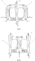
- the crystalliser comprises two vertically positioned loop-shaped 2 conduits having the two upwards flowing sections 5 joined by a common downwards flowing section 6 ( Figure 3A ), or having the two downwards flowing sections 6 joined by a common upwards flowing section 5 ( Figure 3B ).
- This embodiment can be extended to more than two upwards and downwards flowing sections to optimize the crystallisation : by optimising the ratio of the volume in the upward flowing section 5 over the volume in the downward flowing section 6, the ratio of the corresponding residence times is optimised and, thereby, the initialisation of crystallisation, the nucleation, is optimised in the upwards flowing section 5 and the crystal growth is optimised in the downwards flowing section 6 .
- An optimal ratio of the volume in the upward flowing section 5 over the volume in the downward flowing section 6 may range from 0.001 to 1000, or from 0.01 to 100, or from 0.1 to 10.
- the presence of additional upwards or downwards flowing section allows for a process using the crystalliser of the disclosure to be performed on a larger scale, resulting in an increased production of the crystallised product.
- the crystalliser comprises two or more vertically positioned loop-shaped 2 conduits having the two or more upwards flowing sections 5 joined by a common downwards flowing section 6 ( Figure 3A showing 2 conduits ).
- the crystalliser comprises a single outlet 9 for the crystal slurry and a single outlet 10 for the gas after evaporation of the cooling liquid.
- the outlets 9 and 10 are respectively located at the bottom and the top of the common downwards flowing section 6.
- the crystalliser 1 comprises two or more vertically positioned loop-shaped 2 conduits having the two or more downwards flowing sections 5 joined by a common upwards flowing section 6 ( Figure 3B showing 2 conduits).
- the crystalliser comprises an outlet 9 for the crystal slurry and an outlet 10 for the gas after evaporation of the cooling liquid, respectively located at the bottom and the top of each downwards flowing section 6.
- a crystalliser 1 is disclosed.
- This crystalliser can be understood as the extrapolation of the previously disclosed crystalliser with multiple conduits, where the conduits have now been merged into one toroidal-like conduit.
- the crystalliser 1 comprises a vertically positioned cylindrical vessel 26 having a cylindrical body 28 centred inside the cylindrical vessel 26 and open at both upper and lower ends.
- the cylindrical vessel 26 comprises a composition inlet 3 for introducing a composition comprising at least a liquid and solids dissolved in the liquid; a cooling inlet 4 for introducing a cooling liquid; one upwards flowing section 5 for cooling the upward flowing composition through contact with the co-currently upwards flowing cooling liquid; one downwards flowing section 6 for transporting a crystal slurry of crystallised solids from the composition downwards; a bottom section 7 joining the downwards flowing section 6 and the upwards flowing section 5; a top section 8 joining the upwards flowing section 5 and the downwards flowing section 6; an outlet 9 at the bottom section 7 for collecting the crystal slurry; and an outlet 10 at the top section 8 for collecting the cooling liquid in its gaseous state, after it has been converted into a gaseous state through heat exchange with the composition; wherein the composition and the cooling liquid are respectively introduced in the composition inlet (3) and the cooling inlet (4) such that the composition and the cooling liquid flow in the loop-shaped conduit (2) in a co-current manner.
- the composition and the cooling liquid flow co-currently in the crystalliser 1 of the disclosure.
- the crystalliser 1 comprises a vertically positioned loop-shaped conduit 2.
- the cooling liquid and the composition are respectively introduced in the inlets 4 and 3.
- the liquids from the crystal slurry after separation of the crystal slurry, returning from the downwards flowing section 6 to the upwards flowing section 5, drive the composition upwards in the upwards flowing section 5.
- the cooling liquid is warmed-up upon contact with the composition, part of it starts evaporating and producing gas bubbles.
- Both inlets 3 and 4 are preferably located in the upwards flowing section and the inlet 4 is preferably located upstream the inlet 3, in order to facilitate the upwards driving of the composition, in the upwards flowing section 5 being driven upwards.
- the presence of a pump 27 may further facilitate the flow in the upwards flowing section.
- composition and the cooling liquid eventually reach the top of the loop-shaped section 2, the top section 8.
- top section 8 are present the composition and cooling liquid, as well as a gas resulting from the evaporation of the cooling liquid and crystals, resulting from the crystallisation of the dissolved solids in the composition. Said otherwise, at this top section 8, there is a mixture of the crystal slurry and a gas and the liquids of the crystal slurry comprise any remaining non-evaporated cooling liquid and the composition with non-crystallised, therefore still dissolved, solids.
- the gas escapes through the outlet 10, resulting in the convenient separation of the gas from the crystal slurry.
- the crystal slurry flows downwards, in the downwards flowing section 6 of the loop-shaped conduit 2.
- the crystals heavier than the liquids of the crystal slurry settle down and can be collected at the outlet 9.
- the crystals lighter than the liquids of the crystal slurry do not settle and be recycled in the loop. It further results a buoyancy effect which drives the liquids and the lighter crystals of the crystal slurry towards the upwards flowing section 5.
- the liquids and some crystals of the crystal slurry are recycled within the loop-shaped conduit 2, which maximises the yield of crystals: dissolved solids not crystallised in a single loop trajectory can crystallise, from the recycled crystals acting as nucleation seeds, in a subsequent loop trajectory.
- the buoyancy effect and the recycling of the liquids and some crystals of the crystal slurry further provides additional force for driving the cooling liquid and the composition upwards, in the upwards flowing section 5.
- the separation of the crystals at the bottom section 7, rather than being accomplished naturally based on the weight of the crystals may be accomplished by classifying means.
- the classifying means classify the crystals according to their size and separate the crystals of a sufficiently large size, as established by the end user of the crystalliser, and direct those crystals to the outlet 9,whereas the remaining crystals are recycled in the loop-shaped conduit 2.
- the crystalliser therefore has the advantages that, through the loop-shaped conduit, both easy gas separation from the crystal slurry and maximisation of the crystallisation yield are achieved.
- the crystalliser 1 comprises one downwards flowing section 6 inside the cylindrical vessel 28 centred in the cylindrical body 26 and two upwards flowing sections 5, that is one on each side of the cylindrical vessel 28 centred in the cylindrical body 26 ( Figure 3C ).
- Each upwards flowing section comprises an inlet for the composition 3 and an inlet for the cooling liquid 4, located in the bottom section 7 of the crystalliser.
- the inlet for the cooling liquid 4 is located upstream the inlet for the composition 3.
- the cylindrical vessel 28 centred in the cylindrical body 26 comprises an agitator 29.
- the crystallizer comprises an outlet 9 for the crystal slurry and an outlet 10 for the gas after evaporation of the cooling liquid, respectively located at the bottom and the top of the downwards flowing section.
- the agitator is located inside the cylindrical vessel 28 from 15% to 40%, preferably from 20% to 35%, even more preferably from 25% to 30% of the height of the cylindrical vessel 28 upstream the top of the cylindrical vessel 28. With the agitator positioned at this height, the mixing of the incoming crystal slurry is maximised at the same time as back-pressure that would result in the crystal slurry being returned to the downwards flowing section is minimised.
- the crystalliser 1 comprises one upwards flowing section 5 inside the cylindrical vessel 28 centred in the cylindrical body 26 and two downwards flowing sections 6, that is one on each side of the cylindrical vessel 28 centred in the cylindrical body 26 ( Figure 3C). ( Figure 3C ).
- the upwards flowing section comprises an inlet for the composition 3 and an inlet for the cooling liquid 4, located in the bottom section 7 of the crystalliser.
- the cylindrical vessel 28 centred in the cylindrical body 26 further comprises an agitator 29.
- the crystallizer comprises an outlet 9 for the crystal slurry and an outlet 10 for the gas after evaporation of the cooling liquid, respectively located at the bottom and the top of the downwards flowing section.
- the agitator is located inside the cylindrical vessel 28 from 15% to 40%, preferably from 20% to 35%, even more preferably from 25% to 30% of the height of the cylindrical vessel 28 above the bottom of the cylindrical vessel 28. With the agitator positioned at this height, the mixing of the incoming composition and cooling liquid is maximised at the same time as back-pressure that would limit the incoming flows of composition and cooling liquid is minimised.
- the crystalliser further comprises a gas compressor 11 comprising an inlet 12 in fluid communication with the outlet 10 at the top section 8, for a gas to be compressed, and an outlet 13 in fluid communication with the cooling inlet 4, for the gas to be compressed and thereby converted into the cooling liquid.
- a gas compressor 11 When such a gas compressor 11 is connected in this manner to the top section 8, the gas coming out of the outlet 10 can be compressed and fed to the inlet 4, such that the amount of gases being compressed to generate the cooling liquid is minimized.
- a gas compressor allows for the recycling of the off-gases at the outlet 10, and, after being compressed into a liquid, fed to the loop-shaped conduit 2.
- the method of the disclosure may comprise a cooling system 20 comprising a cooler 21 and means for exchanging heat 22 between the coolant from the cooler 21 and the cooling liquid.
- the cooling liquid is thereby cooled to a temperature below the nucleation temperature for the solids to be crystallised, such as ranging from -275 °C to -5 °C, or from -40 °C to -5 °C, or from -15 °C to -5 °C.
- Such cooling system will prevent the evaporation of the cooling liquid, prior to its introduction in the inlet 3 of the crystalliser 1.
- the crystalliser further comprises a separator 14 for separating the gas collected at the outlet 10, at the top section 8, from any crystal slurry carried over at the outlet 10.
- the separator 14 comprises an inlet 15 in fluid communication with the outlet 10 at the top section 8; and, in particular, a first outlet 16 for a gas in fluid communication with the inlet 12 of the gas compressor 11 and a second outlet 17 for the crystal slurry in fluid communication with the composition inlet 3 of the crystalliser 1.
- the crystallisation yield is maximised since the crystal slurry carried over at the outlet 10 is recycled to the loop-shaped conduit 2.
- the crystals of the crystal slurry may settle down at the bottom section 7 for being collected at the outlet 9. Furthermore, the presence of the separator prevents, in cases where there also is a gas compressor 11 and the gases at the outlet 10 are, as described above, recycled to gas compressor 11, the carry-over of solids to the gas compressor 11 which would damage the gas compressor 11.
- the crystalliser further comprises heating means (not shown) for supplying heat to at least part of the walls of the upwards flowing section 5.
- heating means can be selected from a heating mantel or means for injecting steam or means for injecting boiling water.
- the heating means are a heating mantel.
- the heating means prevents that the temperature on the walls of the upwards flowing reaches a temperature that is colder than the optimal range of from -275 °C to 5 °C, or from - 100 °C to 5 °C, or from -40 °C to 5 °C, or from -30 °C to 5 °C, - or from -20 °C to -5 °C, or from -15 °C to -5 °C.
- the temperature onto the walls of upwards flowing section is maintained to a value ranging from 5 °C to 40 °C, or 10 °C to 40 °C, or 15 °C to 40 °C, or 20 °C to 40 °C, or 30 °C to 40 °C, the build-up of crystals onto the walls of the upwards flowing section 5 is prevented such that the crystals can be effectively collected at the outlet 9 at the bottom section 7.
- preventing the build-up of crystals onto these walls facilitates the flow in the upwards flowing section 5 and reduces the chances of blockage due to crystal aggregation.
- the upwards flowing comprises means for measuring the temperature, such as temperature sensors.
- this is possible to identify when the temperature in the upwards flowing section is colder than the optimal range of -275 °C to 5 °C, or from -100 °C to 5 °C, or from -40 °C to 5 °C, or from -30 °C to 5 °C, - or from -20 °C to -5 °C, or from -15 °C to -5 °C and, thereby, identify when heat should be supplied by the heating means 18 to at least part of the walls of the upwards flowing section 5.
- the crystalliser further comprises breaking means 19 in the vicinity of the outlet 9 at the bottom section, for breaking the crystals of the crystal slurry.
- breaking means can be selected from a macerator, an agitator or a macerator.
- the breaking means is a macerator. In the presence of such breaking means, crystals are broken down to nucleation seeds, such that, upon recycling of the seeds into the loop-shaped conduit 2, crystallisation of solids from the composition is favoured.
- a method for crystallising solids from a composition comprising at least a liquid and solids dissolved in the liquid comprises the steps of: a) feeding a cooling liquid to a cooling inlet 4 and a composition comprising at least a liquid and solids dissolved in the liquid to a composition inlet 3 of a crystalliser 1 of the present disclosure; b) collecting the cooling liquid converted into a gaseous state at the outlet 10 at the top section 8 of the crystalliser 1; and c) collecting a crystal slurry at the outlet 9 at the bottom section 7 of the crystalliser 1.
- the presence of this loop-shaped conduit 2 in the method of the disclosure results in the method having both advantages of easy gas separation from the crystal slurry and maximisation of the crystallisation yield.
- the cooling liquid should be a cooling liquid that, in operation under normal operating conditions, is converted into a gaseous state and is collected at the outlet 10 at the top section 8 of the crystalliser . It may be selected from the group of liquid CO 2 , liquid propane, liquid butane, mixtures of liquid propane and liquid butane, freons or liquid N 2 O.
- the temperature of the cooling liquid may range from -275 °C to 5 °C, or from -100 °C to 5 °C, or from -40 °C to 5 °C, or from -30 °C to 5 °C, - or from -20 °C to -5 °C, or from -15 °C to -5 °C.
- the pressure at which the cooling agent exists in the liquid state or, said otherwise, at which the cooling agent is a cooling liquid may be in the range of from 2 to 35 bar, or from 5 to 35 bar, or from 10 to 35 bar, or from 12 to 30 bar, or from 15 to 25 bar.
- the cooling liquid in step a) is liquid CO 2 and is pressurized to a pressure ranging from 10 to 35 bar. Under those conditions, the crystallisation of the solids dissolved in the composition is maximised.
- liquid CO 2 offers the benefit of a safe crystallisation process. Indeed, contrary to organic cooling liquids, in the case that the composition comprises dissolved nitrate-based compounds, the formation of explosive organic nitrates will not take place in the presence of liquid CO 2 .
- the method may comprise a pumping step in which the content in the bottom section 7 of the crystalliser is pumped using a pump 26 towards the upwards flowing section 5, thereby facilitating the flow in the upwards flowing section 5.
- the method comprises a classifying step, in which the crystals at the bottom section 7 of the crystalliser 1 are classified using means for classifying (not shown), such that the crystals of a sufficiently large size, as determined by the end user of the method, are collected at the outlet 9 and the smaller crystals are recycled as seeds in the upwards flowing section 5, thereby facilitating crystal growth in this section.
- the method further comprises an agitation step using an agitator 29 when the method is used in conjunction with a crystalliser 1 according to a particular aspect of the disclosure.
- Such agitation step assists in the mixing of the composition and the cooling liquid, thus favouring the cooling of the composition and, in turn, favouring the crystallisation of the solids dissolved in the composition.
- the method further comprises the steps of, in a crystalliser 1 according to any of the crystallisers of the disclosure and comprising a gas compressor 11, d) compressing the gas collected in step b) using the gas compressor 11, thereby obtaining a cooling liquid; and e) repeating step a) with the cooling liquid obtained in step d).
- the gas generating the cooling liquid can be compressed just prior to the introduction of the cooling liquid in the inlet 3 of the crystalliser 1, or a volume of cooling liquid can be generated prior to the introduction of the cooling liquid in the loo-shaped circuit 2 and stored in a storage tank, shown as 23, at appropriate temperature such as -275 °C to 5 °C, or from -100 °C to 5 °C, or from -40 °C to 5 °C, or from -30 °C to 5 °C, - or from -20 °C to -5 °C, or from -15 °C to -5 °C and pressure conditions such as 2 to 35 bar, or from 5 to 35 bar, or from 10 to 30 bar, or from 12 to 30 bar, or from 15 to 25 bar.
- the method of the disclosure may comprise a step d') in which the cooling liquid is cooled to a temperature ranging from as -275 °C to 5 °C, or from -100 °C to 5 °C, or from -40 °C to 5 °C, or from -30 °C to 5 °C, - or from -20 °C to -5 °C, or from -15 °C to -5 °C, through heat exchange in system 22, with the cooler 20 of a cooling system 21, in order to prevent evaporation of the liquid prior to its introduction in the inlet 3 of the crystalliser 1.
- an additional cooling system for example by heat exchange, may be inserted between the outlet 13 the heat exchange 22.
- the method further comprises the steps of, in a crystalliser 1 according to any of the crystallisers of the disclosure and comprising a separator 14, f) separating the gas collected at the outlet 10 from any crystal slurry carried over at the outlet 10 in the separator 14.
- a crystalliser 1 according to any of the crystallisers of the disclosure and comprising a separator 14, f) separating the gas collected at the outlet 10 from any crystal slurry carried over at the outlet 10 in the separator 14.
- the resulting crystal slurry may be fed to the inlet 3 in the upwards flowing section 5, whereas the gas may be fed to the gas compressor 11 in order to minimize the amount of gas being used for generating the cooling liquid.
- the method further comprises the steps of, in a crystalliser 1 according to any of the crystallisers of the disclosure and comprising heating means (not shown), g) supplying heat by using the heating means (not shown) to at least part of the walls of the upwards flowing section 5.
- the step g) prevents that the temperature on the walls of the upwards flowing reaches a temperature that is colder than the optimal range of from -275 °C to 5 °C, or from -100 °C to 5 °C, or from -40 °C to 5 °C, or from -30 °C to 5 °C, - or from -20 °C to -5 °C, or from -15 °C to -5 °C.
- the temperature onto the walls of upwards flowing section is maintained to a value ranging from 5 °C to 40 °C, or 10 °C to 40 °C, or 15 °C to 40 °C, or 20 °C to 40 °C, or 30 °C to 40 °C, the build-up of crystals onto the walls of the upwards flowing section 5 is prevented such that the crystals can be effectively collected at the outlet 9 at the bottom section 7.
- preventing the build-up of crystals onto these walls facilitates the flow in the upwards flowing section 5 and reduces the chances of blockage due to crystal aggregation.
- the method further comprises a step g') in which the temperature in the upwards flowing section is measured using means for measuring the temperature, such as temperature sensors.
- a step g' in which the temperature in the upwards flowing section is measured using means for measuring the temperature, such as temperature sensors.
- the method further comprises the steps of, in a crystalliser 1 according to any of the crystallisers of the disclosure and comprising breaking means 19, j) breaking the crystals of the crystal slurry by using the breaking means 19.
- breaking means 19 breaking the crystals of the crystal slurry by using the breaking means 19.
- step j crystals are broken down to nucleation seeds, such that, upon recycling of the seeds into the upwards flowing section 5, crystallisation of solids from the composition is favoured.
- the composition is obtained by digesting a phosphate rock or a mixture of phosphate rocks in nitric acid and the crystals formed are calcium nitrate tetra-hydrate crystals.
- the method of the disclosure may indeed be used for performing the crystallisation step in the nitro-phosphate, Odda process.
- the nitro-phosphate process comprises six main steps. In a first step (digestion step), phosphate rock is digested in nitric acid yielding a digestion liquor at a temperature of 65°C, which can be stored in a tank such as 24 in Figure 4 .
- a second step calcium nitrate tetrahydrate is crystallized out of the digestion liquor yielding a crystal slurry.
- a third step the crystallized calcium nitrate is separated by a technique such as filtration (calcium nitrate tetrahydrate crystals are shown as 25 in Figure 4 ) or centrifugation, resulting in calcium nitrate tetrahydrate crystals being separated from the liquid of the crystal slurry, referred to as the mother liquor.
- a fourth step neutralization step
- the mother liquor is neutralized using ammonia up to a pH of approximately 5.8.
- the neutralized mother liquor is particulated into the final product (e.g. for use as an NP-fertilizer).
- Potassium salts can be added during the neutralization process or to the neutralized mother liquor.
- an evaporation step is performed upfront the addition of potassium salts, in order to reach a water content sufficiently low to perform prilling.
- the particles can be subsequently coated, for example with a coating agent suitable for reducing moisture absorption and for, thereby, ensuring proper physical properties for the particles.
- the second, crystallisation step of the nitro-phosphate process may be performed using the method of the disclosure.
- the current crystallisers used in the nitro-phosphate process are traditionally apparatuses such as described in GB1012721A (Laporte Chemicals Ltd., 1961) and comprising cooling coils, over which the heat of the digestion liquor is exchanged , which results in the crystallization of calcium nitrate tetrahydrate.
- the replacement of heat transfer through heating coils with the direct physical contact between the cooling liquid and the digestion liquor allows for the reduction of the costs associated to the crystalliser itself and also to the operation of the crystalliser. This replacement further results in an improved crystallization efficiency.
- the digestion liquor and the calcium nitrate tetrahydrate crystal slurry are efficiently separated. Consequently, the crystal slurry is produced in a more concentrated form in the method of the disclosure, with respect to the traditional method. As a result, the separation of the crystals from the crystal slurry is facilitated.
- the method of the disclosure can be performed batchwise or continuously. According to one embodiment of the method of the disclosure (batchwise), step a) is first performed, followed by steps b) and c), which may be performed simultaneously. According to another embodiment of the method of the disclosure (continuous), steps a), b) and c) are performed simultaneously.
- a particular advantage of the method of the disclosure is that it allows for continuous feeding of composition and cooling liquid to the inlets 3 and 4 respectively upon continuous collection of the crystal slurry at the outlet 9 and continuous collection of the gas at the outlet 10. Therefore, the method for crystallising does not need to be applied in a batchwise manner but can be performed as a continuous method.
- a nitrophosphate digestion liquor comprising from 7.5 weight% nitric acid, from 14.4 weight% phosphoric acid and 45.1 weight% dissolved calcium nitrate tetrahydrate is continuously fed to the composition inlet 3 of a loop-shaped conduit 2 at a flow rate of 36.6 kg/s.
- the loop-shaped conduit 2 comprised a composition inlet 3 for introducing a composition comprising at least a liquid and solids dissolved in the liquid; a cooling inlet 4 for introducing a cooling liquid, located upstream the composition inlet 3; one upwards flowing section 5, comprising the composition inlet 3 and the cooling inlet 4, for cooling the upwards flowing composition through contact with the co-currently upwards flowing cooling liquid; one downwards flowing section 6 for transporting a crystal slurry of crystallised solids from the composition downwards; a bottom section 7 joining the downwards flowing section 6 and the upwards flowing section 5; a top section 8 joining the upwards flowing section 5 and the downwards flowing section 6; an outlet 9 at the bottom section 7 for collecting the crystal slurry; and an outlet 10 at the top section 8 for collecting the cooling liquid in its gaseous state, after it has been converted into a gaseous state through heat exchange with the composition.
- Liquid CO 2 at a pressure of 30 bar and a temperature of -5.5 °C is also continuously fed as the cooling liquid in the loop-shaped conduit, at the cooling inlet 4 of the loop-shaped conduit 2, at a flow rate of 36.6 kg/s.
- Gaseous CO 2 is continuously collected at the outlet 10 at the top section 8 of the loop-shaped conduit 2 and a calcium nitrate tetrahydrate crystal slurry is continuously collected at the outlet 9 at the bottom section 7 of the loop-shaped conduit 2.
- a crystalliser comprising the loop-shaped conduit 2 further comprises a gas compressor 11.
- the crystalliser further comprises a separator 14.
- the crystalliser comprises a heating mantel 18 as heating means, surrounding the walls of the upwards flowing section 5.
- the crystalliser comprises a macerator 19 as breaking means, located in the vicinity and on the right side of the outlet 9 at the bottom section 7. Gaseous CO 2 and carry over of calcium nitrate tetrahydrate crystal slurry, collected at the outlet 10 at the top section 8, are separated in the separator 14.
- the separated gaseous CO 2 is then fed to the compressor 11 in order for additional liquid CO 2 to be produced as a source of cooling liquid.
- the carry-over of calcium nitrate tetrahydrate crystal slurry is fed to the composition inlet 3 of the loop shaped conduit 2. In this manner, the yield of calcium nitrate tetrahydrate crystals in maximised.
- Heat is provided through the heating mantel 18 to the walls of the upwards flowing section 5, which prevents formation of calcium nitrate tetrahydrate crystals on those walls and allows for a continuous and non-obstructed flow in the upwards flowing section 5.
Landscapes
- Chemical & Material Sciences (AREA)
- Crystallography & Structural Chemistry (AREA)
- Chemical Kinetics & Catalysis (AREA)
- Physics & Mathematics (AREA)
- Thermal Sciences (AREA)
- Organic Chemistry (AREA)
- Geology (AREA)
- Inorganic Chemistry (AREA)
- Life Sciences & Earth Sciences (AREA)
- Vaporization, Distillation, Condensation, Sublimation, And Cold Traps (AREA)
- Organic Low-Molecular-Weight Compounds And Preparation Thereof (AREA)
- Crystals, And After-Treatments Of Crystals (AREA)
- Extraction Or Liquid Replacement (AREA)
Abstract
The present disclosure relates to a vertically positioned crystalliser (1) comprising at least one upwards flowing section (5) for cooling the upwards flowing composition physically separated from at least one downwards flowing section (6) for transporting a crystal slurry of crystallised solids from the composition downwards; the crystalliser (1) further comprising:• at least one composition inlet (3) for introducing a composition comprising at least a liquid and solids dissolved in said liquid;• at least one cooling inlet (4) for introducing a cooling liquid;• a bottom section (7) where the downwards flowing section (6) and the upwards flowing section (5) fluidically join comprising at least one outlet (9) for collecting the crystal slurry; and;• a top section (8) where the upwards flowing section (5) and the downwards flowing section (6) fluidically join comprising at least one outlet (10) for collecting the cooling liquid in gaseous state;wherein the at least one composition inlet (3) and the at least one cooling inlet (4) are located in the vertically positioned crystalliser (1) such that in the at least one upwards flowing section (5) the cooling liquid and the composition are co-currently flowing upwards.
Description
- The present disclosure relates to the field of crystalliser apparatuses. It further relates to the field of methods for crystallising and to the use of crystallisers for performing those methods.
- Crystallisation is the natural or artificial process by which a solid forms, where the atoms or molecules are highly organized into a structure known as a crystal. Some of the ways by which crystals form are precipitating from a solution, freezing, or more rarely deposition directly from a gas. Attributes of the resulting crystal depend largely on factors such as temperature, air pressure, and in the case of liquid crystals, time of fluid evaporation.
- Crystallisation occurs in two major steps. The first is nucleation, the appearance of a crystalline phase from either a supercooled liquid or a supersaturated solvent. The second step is known as crystal growth, which is the increase in the size of particles and leads to a crystal state. An important feature of this step is that loose particles form layers at the crystal's surface and lodge themselves into open inconsistencies such as pores, cracks or their equivalents.
- Crystallisation is also a chemical solid-liquid separation technique, in which mass transfer of a solute from the liquid solution to a pure solid crystalline phase occurs. In chemical engineering, crystallisation occurs in a crystalliser. Crystallisation is therefore related to precipitation, although the result is not an amorphous or disordered substance, but a crystal.
- A possibility to achieve crystallisation is to cool the solution from which crystals are to be formed. This cooling can be achieved through either direct or indirect heat transfer. In indirect heat transfer, a coolant and the solution to be cooled are circulated in separate closed chambers without direct physical contact, for example in a heat exchanger. In direct heat transfer, the coolant and the solution to be cooled are brought into direct physical contact, in a single compartment that is the crystallisation chamber of the crystalliser.
-
GB932215 (Cerny, 1960 -
US4452621 (Mobil Oil Corporation, 1984) discloses a crystallisation process that is improved by employing direct contact cooling whereby a volatile liquid is vaporized to provide the cooling necessary to effect the crystallisation. The effluent vapours of the volatile liquid may be liquified and recycled for reuse by manipulation of temperature and/or pressure. In one embodiment, durene is crystallised from a C10 aromatics fraction using liquified n-butane as the coolant. - In order to reduce the crystallisation time and thereby improve the process capacity and/or efficiency, it is essential to optimize the crystallisation efficiency. It is particularly important to ensure that the consumption of the cooling agent is minimised and that the crystallisation yield from the solution from which crystallisation is to be performed is maximised. In other words, the maximum crystal formation should be achieved at the minimum consumption of the cooling agent. In addition, the chosen cooling agent should provide the proper cooling conditions under optimal pressure and temperature conditions, at the same time as being compatible with the solution, which means that the crystallisation process should be safe to perform.
- In a first aspect of the disclosure, a crystalliser is disclosed. The crystalliser is a vertically positioned crystalliser (1) comprising at least one upwards flowing section (5) for cooling the upwards flowing composition physically separated from at least one downwards flowing section (6) for transporting a crystal slurry of crystallised solids from the composition downwards; the crystalliser (1) further comprising:
- at least one composition inlet (3) for introducing a composition comprising at least a liquid and solids dissolved in said liquid;
- at least one cooling inlet (4) for introducing a cooling liquid;
- a bottom section (7) where the downwards flowing section (6) and the upwards flowing section (5) fluidically join comprising at least one outlet (9) for collecting the crystal slurry; and;
- a top section (8) where the upwards flowing section (5) and the downwards flowing section (6) fluidically join comprising at least one outlet (10) for collecting the cooling liquid in gaseous state;
- In a particular embodiment, the crystalliser comprises a vertically positioned loop-shaped conduit which comprises a composition inlet for introducing a composition comprising at least a liquid and solids dissolved in the liquid; a cooling inlet for introducing a cooling liquid; one upwards flowing section for cooling the upwards flowing composition through contact with the co-currently upwards flowing cooling liquid; one downwards flowing section for transporting a crystal slurry of crystallised solids from the composition downwards; a bottom section joining the downwards flowing section and the upwards flowing section; a top section joining the upwards flowing section and the downwards flowing section; an outlet at the bottom section for collecting the crystal slurry; and an outlet at the top section for collecting the cooling liquid in its gaseous state, after it has been converted into a gaseous state through heat exchange with the composition; wherein the composition and the cooling liquid are respectively introduced in the composition inlet and the cooling inlet such that the composition and the cooling liquid flow in the loop-shaped conduit in a co-current manner.
- In an alternative embodiment, the crystalliser comprises a vertically positioned cylindrical vessel having a cylindrical body centred inside the cylindrical vessel and open at both upper and lower ends. The cylindrical vessel comprises a composition inlet for introducing a composition comprising at least a liquid and solids dissolved in the liquid; a cooling inlet for introducing a cooling liquid; one upwards flowing section for cooling the upwards flowing composition through contact with the co-currently upwards flowing cooling liquid; one downwards flowing section for transporting a crystal slurry of crystallised solids from the composition downwards; a bottom section joining the downwards flowing section and the upwards flowing section; a top section joining the upwards flowing section and the downwards flowing section; an outlet at the bottom section for collecting the crystal slurry; and an outlet at the top section for collecting the cooling liquid in its gaseous state, after it has been converted into a gaseous state through heat exchange with the composition; wherein the composition and the cooling liquid are respectively introduced in the composition inlet and the cooling inlet such that the composition and the cooling liquid flow in the loop-shaped conduit in a co-current manner
- In a second aspect of the disclosure, a method for crystallising solids from a composition comprising at least a liquid and solids dissolved in the liquid is disclosed. The method comprises the steps of: a) feeding a cooling liquid to a cooling inlet and a composition comprising at least a liquid and solids dissolved in the liquid to a composition inlet of a crystalliser according to any of the crystallisers of the present disclosure; b) collecting the cooling liquid converted into a gaseous state at the outlet at the top section of the crystalliser; and c) collecting a crystal slurry at the outlet at the bottom section of the crystalliser.
- In a third aspect of the disclosure, the use of any of the crystallisers of the present disclosure for performing a method for crystallising according to the present disclosure, is disclosed.
-
-
Figure 1 shows a schematic representation of a loop-shaped conduit 2 according to the first aspect of the disclosure -
Figure 2 shows a schematic representation of acrystalliser 1 according to the first aspect of the disclosure and comprising acompressor 11 -
Figure 3A shows a schematic representation of acrystalliser 1 according to the first aspect of the disclosure and comprising multiple upwards flowing sections 5 -
Figure 3B shows a schematic representation of acrystalliser 1 according to the first disclosure and comprising multiple downwards flowingsections 6 -
Figure 3C shows a schematic representation of acrystalliser 1 according to the first aspect of the disclosure and comprising multiple upwards flowing sections 5 -
Figure 3D shows a schematic representation of acrystalliser 1 according to the first aspect of the disclosure and comprising multiple downwards flowingsections 6 -
Figure 4 shows a flow diagram of the crystallisation step of the Odda, nitro-phosphate process utilising any crystalliser according to the disclosure - Throughout the description and claims of this specification, the words "comprise" and variations thereof mean "including but not limited to", and they are not intended to (and do not) exclude other moieties, additives, components, integers or steps. Throughout the description and claims of this disclosure, the singular encompasses the plural unless the context otherwise requires. In particular, where the indefinite article is used, the disclosure is to be understood as contemplating plurality as well as singularity, unless the context requires otherwise.
- Features, integers, characteristics, compounds, chemical moieties, or groups described in conjunction with a particular aspect, embodiment or example of the disclosure are to be understood to be applicable to any other aspect, embodiment or example described herein unless incompatible therewith. All of the features disclosed in this disclosure (including the description, claims, abstract and drawings), and/or all of the steps of any method or process so disclosed, may be combined in any combination, except combinations where at least some of such features and/or steps are mutually exclusive. The disclosure is not restricted to the details of any foregoing embodiments. The disclosure extends to any novel one, or any novel combination, of the features disclosed in this disclosure (including the description, claims, abstract and drawings), or to any novel one, or any novel combination, of the steps of any method or process so disclosed.
- The enumeration of numeric values by means of ranges of figures comprises all values and fractions in these ranges, as well as the cited end points. The term "ranges from ... to " as used when referring to a range for a measurable value, such as a parameter, an amount, a time period, and the like, is intended to include the limits associated to the range that is disclosed.
- By way of example, embodiments of the crystalliser will be discussed using the following figures, where the numerals refer to the same or a similar features in the figures.
- In a first aspect the present disclosure relates to a vertically positioned crystalliser (1) comprising at least one upwards flowing section (5) for cooling the upwards flowing composition physically separated from at least one downwards flowing section (6) for transporting a crystal slurry of crystallised solids from the composition downwards; the crystalliser (1) further comprising:
- at least one composition inlet (3) for introducing a composition comprising at least a liquid and solids dissolved in said liquid;
- at least one cooling inlet (4) for introducing a cooling liquid;
- a bottom section (7) where the downwards flowing section (6) and the upwards flowing section (5) fluidically join comprising at least one outlet (9) for collecting the crystal slurry; and;
- a top section (8) where the upwards flowing section (5) and the downwards flowing section (6) fluidically join comprising at least one outlet (10) for collecting the cooling liquid in gaseous state;
- The co-currently upwards flowing of the cooling liquid and the composition can be attained in a number of ways. In a particular embodiment the crystalliser (1) as disclosed herein comprises:
- at least one vertically positioned loop-shaped conduit (2), said loop-shaped conduit (2) comprising the at least one upwards flowing section (5); or
- two or more vertically positioned loop-shaped conduits (2) comprising two or more upwards flowing sections (5) and a single common downwards flowing section (6); or
- two or more vertically positioned loop-shaped conduits (2) comprising two or more downwards flowing sections (6) and a single common upwards flowing section (5).
- By providing one or more loop-shaped conduits the upwards flowing section (5) and downwards flowing section (6) are physically separated from each other, fluidically joining each other only at the bottom section (7) and the top section (8).
- In an alternative embodiment the crystalliser (1) as disclosed herein comprises a vertically positioned cylindrical vessel (26) comprising a cylindrical body (28) centred inside said cylindrical vessel (26) and open at both upper and lower ends physically separating the upwards flowing section (5) from the downwards flowing section (6).
- Contrary to the prior art
GB932215 (Cerny, 1960 US4452621 , the composition and the cooling liquid flow co-currently in thecrystalliser 1 of the disclosure. The cooling liquid and the composition are respectively introduced in the inlets 4 and 3. The liquids from the crystal slurry, after separation of the crystal slurry, returning from the downwards flowingsection 6 to the upwards flowing section 5, drive the composition upwards in the upwards flowing section 5. In addition, as the cooling liquid is warmed-up upon contact with the composition, part of it starts evaporating and producing gas bubbles. The result is, therefore, that both the cooling liquid, as part of it evaporates, and the composition flow in an upwards direction, in the upwards flowing section 5 of thecrystalliser 1. The composition is being cooled down, through contact with the cooling liquid, the solids dissolved in the composition start crystallising, resulting in the production of a crystal slurry. The composition and the cooling liquid eventually reach thetop section 8. At thistop section 8 are present the composition and cooling liquid, as well as a gas resulting from the evaporation of the cooling liquid and crystals, resulting from the crystallisation of the dissolved solids in the composition. Said otherwise, at thistop section 8, there is a mixture of the crystal slurry and a gas and the liquids of the crystal slurry comprise any remaining non-evaporated cooling liquid and the composition with non-crystallised, therefore still dissolved, solids. As the gas is lighter than the crystal slurry, the gas escapes through theoutlet 10, resulting in the convenient separation of the gas from the crystal slurry. On the other hand, the crystal slurry flows downwards, in the downwards flowingsection 6. Once the crystal slurry reaches thebottom section 7, the crystals heavier than the liquids of the crystal slurry, settle down and can be collected at the outlet 9. The crystals lighter than the liquids of the crystal slurry do not settle and are recycled. It further results a buoyancy effect which drives the liquids and the lighter crystals of the crystal slurry towards the upwards flowing section 5. As a result, the liquids and some crystals of the crystal slurry are recycled within the upwards flowing section 5, which maximises the yield of crystals: dissolved solids not crystallised in a first trajectory can crystallise, from the recycled crystals acting as nucleation seeds, in a subsequent trajectory. The buoyancy effect and the recycling of the liquids and some crystals of the crystal slurry further provides additional force for driving the cooling liquid and the composition upwards, in the upwards flowing section 5. The crystalliser therefore has the advantages that both easy gas separation from the crystal slurry and maximisation of the crystallisation yield are achieved. In a particular embodiment the crystalliser (1) as disclosed herein provides that the composition inlet (3) and the cooling inlet (4) are located in the upwards flowing section (5). - In a particular embodiment the crystalliser (1) as disclosed herein provides that the cooling inlet (4) is located upstream from the composition inlet (3).
- In a particular embodiment the crystalliser (1) as disclosed herein further comprises a gas compressor (11) upstream from outlet (10), for compressing cooling liquid in gaseous state and reintroducing said cooling liquid in said crystallizer (1) through cooling inlet (4).
- In a particular embodiment the crystalliser (1) as disclosed herein further comprises a separator (14) for separating the gas collected at the outlet (10), at the top section (8), from any crystal slurry carried over at the outlet (10), wherein the separator (14) comprises:
- an inlet (15) in fluid communication with the outlet (10) at the top section (8); and, in particular;
- a first outlet (16) for a gas in fluid communication with the inlet (12) of the gas compressor (11); and
- a second outlet (17) for the crystal slurry in fluid communication with the first inlet (3) of the crystalliser (1).
- In a particular embodiment the crystalliser (1) as disclosed herein further comprises heating means (18) for supplying heat to at least part of the walls of the upwards flowing section (5).
- In a particular embodiment the crystalliser (1) as disclosed herein further comprises breaking means (19) in the vicinity of outlet (9) at the bottom section (7), for breaking the crystals of the crystal slurry.
- In a second aspect the present disclosure provides in a method for crystallising solids from a composition comprising at least a liquid and solids dissolved in the liquid, comprising the steps of:
- (a) feeding a cooling liquid to a cooling inlet (4) and the composition comprising at least a liquid and solids dissolved in the liquid to a composition inlet (3) of a crystalliser (1) as disclosed herein;
- (b) collecting the cooling liquid converted into a gaseous state at the outlet (10) at the top section (8) of the crystalliser (1); and
- (c) collecting a crystal slurry at the outlet (9) at the bottom section (7) of the crystalliser (1).
- In a particular embodiment the method as disclosed herein provides that the cooling liquid in step (a) is liquid CO2 and is pressurized to a pressure ranging from 10 to 35 bars.
- In a particular embodiment the method as disclosed herein further comprises the steps of:
- (d) compressing the gas collected in step (b) using a gas compressor (11), thereby obtaining a cooling liquid; and
- (e) repeating step (a) with the cooling liquid obtained in step (d).
- In a particular embodiment the method as disclosed herein further comprises the steps of:
(f) separating the gas collected at the outlet (10) from any crystal slurry carried over at the outlet (10) in a separator (14). - In a particular embodiment the method as disclosed herein further comprises the steps of:
(g) supplying heat by using heating means (18) to at least part of the walls of the upwards flowing section (5). - In a particular embodiment the method as disclosed herein further comprises the steps of:
(j) breaking the crystals of the crystal slurry by using breaking means (19). - In a particular embodiment the method as disclosed herein provides that the composition is obtained by digesting a phosphate rock or a mixture of phosphate rocks in nitric acid and wherein the crystals formed are calcium nitrate tetra-hydrate crystals.
- In a particular embodiment the method as disclosed herein is performed in a continuous manner and steps (a), (b) and (c) are performed simultaneously.
- In a third aspect the present disclosure provides in the use of a crystalliser (1) as disclosed herein for performing a method for crystallising as disclosed herein.
- In a particular embodiment the use as disclosed herein provides in the crystallisation of calcium nitrate tetrahydrate crystals from a nitrophosphate digestion liquor comprising nitric acid, phosphoric acid and dissolved calcium nitrate tetrahydrate.
- With reference to
Figure 1 , in a particular aspect of the disclosure, acrystalliser 1 is disclosed. The crystalliser comprises a vertically positioned loop-shapedconduit 2 which comprises a composition inlet 3 for introducing a composition comprising at least a liquid and solids dissolved in the liquid; a cooling inlet 4 for introducing a cooling liquid; one upwards flowing section 5 for cooling the upward flowing composition through contact with the co-currently upwards flowing cooling liquid; one downwards flowingsection 6 for transporting a crystal slurry of crystallised solids from the composition downwards; abottom section 7 joining the downwards flowingsection 6 and the upwards flowing section 5; atop section 8 joining the upwards flowing section 5 and the downwards flowingsection 6; an outlet 9 at thebottom section 7 for collecting the crystal slurry; and anoutlet 10 at thetop section 8 for collecting the cooling liquid in its gaseous state, after it has been converted into a gaseous state through heat exchange with the composition; wherein the composition and the cooling liquid are respectively introduced in the composition inlet (3) and the cooling inlet (4) such that the composition and the cooling liquid flow in the loop-shaped conduit (2) in a co-current manner. - Contrary to the prior art
GB932215 (Cerny, 1960 US4452621 , the composition and the cooling liquid flow co-currently in thecrystalliser 1 of the disclosure. Indeed, thecrystalliser 1 comprises a vertically positioned loop-shapedconduit 2. The cooling liquid and the composition are respectively introduced in the inlets 4 and 3. The liquids from the crystal slurry, after separation of the crystal slurry, returning from the downwards flowingsection 6 to the upwards flowing section 5, drive the composition upwards in the upwards flowing section 5. In addition, as the cooling liquid is warmed-up upon contact with the composition, part of it starts evaporating and producing gas bubbles. The result is, therefore, that both the cooling liquid, as part of it evaporates, and the composition flow in an upwards direction, in the upwards flowing section 5 of the loop-shapedconduit 2. Both inlets 3 and 4 are preferably located in the upwards flowing section and the inlet 4 is preferably located upstream the inlet 3, in order to facilitate the upwards driving of the composition, in the upwards flowing section 5 being driven upwards. Optionally, the presence of a pump 27 may further facilitate the flow in the upwards flowing section. The composition is being cooled down, through contact with the cooling liquid, the solids dissolved in the composition start crystallising, resulting in the production of a crystal slurry. - The composition and the cooling liquid eventually reach the top of the loop-shaped
section 2, thetop section 8. At thistop section 8 are present the composition and cooling liquid, as well as a gas resulting from the evaporation of the cooling liquid and crystals, resulting from the crystallisation of the dissolved solids in the composition. Said otherwise, at thistop section 8, there is a mixture of the crystal slurry and a gas and the liquids of the crystal slurry comprise any remaining non-evaporated cooling liquid and the composition with non-crystallised, therefore still dissolved, solids. - As the gas is lighter than the crystal slurry, the gas escapes through the
outlet 10, resulting in the convenient separation of the gas from the crystal slurry. On the other hand, the crystal slurry flows downwards, in the downwards flowingsection 6 of the loop-shapedconduit 2. Once the crystal slurry reaches thebottom section 7 of the loop-shapedconduit 2, the crystals heavier than the liquids of the crystal slurry, settle down and can be collected at the outlet 9. The crystals lighter than the liquids of the crystal slurry do not settle and be recycled in the loop. It further results a buoyancy effect which drives the liquids and the lighter crystals of the crystal slurry towards the upwards flowing section 5. As a result, the liquids and some crystals of the crystal slurry are recycled within the loop-shapedconduit 2, which maximises the yield of crystals: dissolved solids not crystallised in a single loop trajectory can crystallise, from the recycled crystals acting as nucleation seeds, in a subsequent loop trajectory. The buoyancy effect and the recycling of the liquids and some crystals of the crystal slurry further provides additional force for driving the cooling liquid and the composition upwards, in the upwards flowing section 5. Optionally, the separation of the crystals at thebottom section 7, rather than being accomplished naturally based on the weight of the crystals, may be accomplished by classifying means (not shown). The classifying means classify the crystals according to their size and separate the crystals of a sufficiently large size, as established by the end user of the crystalliser, and direct those crystals to the outlet 9,whereas the remaining crystals are recycled in the loop-shapedconduit 2. - The crystalliser therefore has the advantages that, through the loop-shaped conduit, both easy gas separation from the crystal slurry and maximisation of the crystallisation yield are achieved.
- Referring to
Figures 3A and 3B , according to one embodiment of the crystalliser of the first aspect of the disclosure, the crystalliser comprises two vertically positioned loop-shaped 2 conduits having the two upwards flowing sections 5 joined by a common downwards flowing section 6 (Figure 3A ), or having the two downwards flowingsections 6 joined by a common upwards flowing section 5 (Figure 3B ). This embodiment can be extended to more than two upwards and downwards flowing sections to optimize the crystallisation : by optimising the ratio of the volume in the upward flowing section 5 over the volume in the downward flowingsection 6, the ratio of the corresponding residence times is optimised and, thereby, the initialisation of crystallisation, the nucleation, is optimised in the upwards flowing section 5 and the crystal growth is optimised in the downwards flowingsection 6 . An optimal ratio of the volume in the upward flowing section 5 over the volume in the downward flowingsection 6 may range from 0.001 to 1000, or from 0.01 to 100, or from 0.1 to 10. In addition, the presence of additional upwards or downwards flowing section allows for a process using the crystalliser of the disclosure to be performed on a larger scale, resulting in an increased production of the crystallised product. - In a particular embodiment, the crystalliser comprises two or more vertically positioned loop-shaped 2 conduits having the two or more upwards flowing sections 5 joined by a common downwards flowing section 6 (
Figure 3A showing 2 conduits ). The crystalliser comprises a single outlet 9 for the crystal slurry and asingle outlet 10 for the gas after evaporation of the cooling liquid. Theoutlets 9 and 10 are respectively located at the bottom and the top of the common downwards flowingsection 6. - In a particular embodiment, the
crystalliser 1 comprises two or more vertically positioned loop-shaped 2 conduits having the two or more downwards flowing sections 5 joined by a common upwards flowing section 6 (Figure 3B showing 2 conduits). The crystalliser comprises an outlet 9 for the crystal slurry and anoutlet 10 for the gas after evaporation of the cooling liquid, respectively located at the bottom and the top of each downwards flowingsection 6. - Referring to
Figures 3C and 3D , in a particular aspect of the disclosure, acrystalliser 1 is disclosed. This crystalliser can be understood as the extrapolation of the previously disclosed crystalliser with multiple conduits, where the conduits have now been merged into one toroidal-like conduit. Thecrystalliser 1 comprises a vertically positionedcylindrical vessel 26 having acylindrical body 28 centred inside thecylindrical vessel 26 and open at both upper and lower ends. Thecylindrical vessel 26 comprises a composition inlet 3 for introducing a composition comprising at least a liquid and solids dissolved in the liquid; a cooling inlet 4 for introducing a cooling liquid; one upwards flowing section 5 for cooling the upward flowing composition through contact with the co-currently upwards flowing cooling liquid; one downwards flowingsection 6 for transporting a crystal slurry of crystallised solids from the composition downwards; abottom section 7 joining the downwards flowingsection 6 and the upwards flowing section 5; atop section 8 joining the upwards flowing section 5 and the downwards flowingsection 6; an outlet 9 at thebottom section 7 for collecting the crystal slurry; and anoutlet 10 at thetop section 8 for collecting the cooling liquid in its gaseous state, after it has been converted into a gaseous state through heat exchange with the composition; wherein the composition and the cooling liquid are respectively introduced in the composition inlet (3) and the cooling inlet (4) such that the composition and the cooling liquid flow in the loop-shaped conduit (2) in a co-current manner. - Contrary to the prior art
GB932215 (Cerny, 1960 US4452621 , the composition and the cooling liquid flow co-currently in thecrystalliser 1 of the disclosure. Indeed, thecrystalliser 1 comprises a vertically positioned loop-shapedconduit 2. The cooling liquid and the composition are respectively introduced in the inlets 4 and 3. The liquids from the crystal slurry, after separation of the crystal slurry, returning from the downwards flowingsection 6 to the upwards flowing section 5, drive the composition upwards in the upwards flowing section 5. In addition, as the cooling liquid is warmed-up upon contact with the composition, part of it starts evaporating and producing gas bubbles. The result is, therefore, that both the cooling liquid, as part of it evaporates, and the composition flow in an upwards direction, in the upwards flowing section 5 of the loop-shapedconduit 2. Both inlets 3 and 4 are preferably located in the upwards flowing section and the inlet 4 is preferably located upstream the inlet 3, in order to facilitate the upwards driving of the composition, in the upwards flowing section 5 being driven upwards. Optionally, the presence of a pump 27 may further facilitate the flow in the upwards flowing section. The composition is being cooled down, through contact with the cooling liquid, the solids dissolved in the composition start crystallising, resulting in the production of a crystal slurry. - The composition and the cooling liquid eventually reach the top of the loop-shaped
section 2, thetop section 8. At thistop section 8 are present the composition and cooling liquid, as well as a gas resulting from the evaporation of the cooling liquid and crystals, resulting from the crystallisation of the dissolved solids in the composition. Said otherwise, at thistop section 8, there is a mixture of the crystal slurry and a gas and the liquids of the crystal slurry comprise any remaining non-evaporated cooling liquid and the composition with non-crystallised, therefore still dissolved, solids. - As the gas is lighter than the crystal slurry, the gas escapes through the
outlet 10, resulting in the convenient separation of the gas from the crystal slurry. On the other hand, the crystal slurry flows downwards, in the downwards flowingsection 6 of the loop-shapedconduit 2. Once the crystal slurry reaches thebottom section 7 of the loop-shapedconduit 2, the crystals heavier than the liquids of the crystal slurry, settle down and can be collected at the outlet 9. The crystals lighter than the liquids of the crystal slurry do not settle and be recycled in the loop. It further results a buoyancy effect which drives the liquids and the lighter crystals of the crystal slurry towards the upwards flowing section 5. As a result, the liquids and some crystals of the crystal slurry are recycled within the loop-shapedconduit 2, which maximises the yield of crystals: dissolved solids not crystallised in a single loop trajectory can crystallise, from the recycled crystals acting as nucleation seeds, in a subsequent loop trajectory. The buoyancy effect and the recycling of the liquids and some crystals of the crystal slurry further provides additional force for driving the cooling liquid and the composition upwards, in the upwards flowing section 5. Optionally, the separation of the crystals at thebottom section 7, rather than being accomplished naturally based on the weight of the crystals, may be accomplished by classifying means. The classifying means classify the crystals according to their size and separate the crystals of a sufficiently large size, as established by the end user of the crystalliser, and direct those crystals to the outlet 9,whereas the remaining crystals are recycled in the loop-shapedconduit 2. - The crystalliser therefore has the advantages that, through the loop-shaped conduit, both easy gas separation from the crystal slurry and maximisation of the crystallisation yield are achieved.
- In a particular embodiment, the
crystalliser 1 comprises one downwards flowingsection 6 inside thecylindrical vessel 28 centred in thecylindrical body 26 and two upwards flowing sections 5, that is one on each side of thecylindrical vessel 28 centred in the cylindrical body 26 (Figure 3C ). Each upwards flowing section comprises an inlet for the composition 3 and an inlet for the cooling liquid 4, located in thebottom section 7 of the crystalliser. The inlet for the cooling liquid 4 is located upstream the inlet for the composition 3. Thecylindrical vessel 28 centred in thecylindrical body 26 comprises an agitator 29. The crystallizer comprises an outlet 9 for the crystal slurry and anoutlet 10 for the gas after evaporation of the cooling liquid, respectively located at the bottom and the top of the downwards flowing section. The agitator is located inside thecylindrical vessel 28 from 15% to 40%, preferably from 20% to 35%, even more preferably from 25% to 30% of the height of thecylindrical vessel 28 upstream the top of thecylindrical vessel 28. With the agitator positioned at this height, the mixing of the incoming crystal slurry is maximised at the same time as back-pressure that would result in the crystal slurry being returned to the downwards flowing section is minimised. - In a particular embodiment, the
crystalliser 1 comprises one upwards flowing section 5 inside thecylindrical vessel 28 centred in thecylindrical body 26 and two downwards flowingsections 6, that is one on each side of thecylindrical vessel 28 centred in the cylindrical body 26 (Figure 3C). (Figure 3C ). The upwards flowing section comprises an inlet for the composition 3 and an inlet for the cooling liquid 4, located in thebottom section 7 of the crystalliser. Thecylindrical vessel 28 centred in thecylindrical body 26 further comprises an agitator 29. The crystallizer comprises an outlet 9 for the crystal slurry and anoutlet 10 for the gas after evaporation of the cooling liquid, respectively located at the bottom and the top of the downwards flowing section. The agitator is located inside thecylindrical vessel 28 from 15% to 40%, preferably from 20% to 35%, even more preferably from 25% to 30% of the height of thecylindrical vessel 28 above the bottom of thecylindrical vessel 28. With the agitator positioned at this height, the mixing of the incoming composition and cooling liquid is maximised at the same time as back-pressure that would limit the incoming flows of composition and cooling liquid is minimised. - Referring to
Figure 2 , according to one embodiment of any of the crystallisers of the disclosure, the crystalliser further comprises agas compressor 11 comprising aninlet 12 in fluid communication with theoutlet 10 at thetop section 8, for a gas to be compressed, and anoutlet 13 in fluid communication with the cooling inlet 4, for the gas to be compressed and thereby converted into the cooling liquid. When such agas compressor 11 is connected in this manner to thetop section 8, the gas coming out of theoutlet 10 can be compressed and fed to the inlet 4, such that the amount of gases being compressed to generate the cooling liquid is minimized. In other words, a gas compressor allows for the recycling of the off-gases at theoutlet 10, and, after being compressed into a liquid, fed to the loop-shapedconduit 2. - In addition and as illustrated in
Figure 4 , the method of the disclosure may comprise acooling system 20 comprising a cooler 21 and means for exchangingheat 22 between the coolant from the cooler 21 and the cooling liquid. The cooling liquid is thereby cooled to a temperature below the nucleation temperature for the solids to be crystallised, such as ranging from -275 °C to -5 °C, or from -40 °C to -5 °C, or from -15 °C to -5 °C. Such cooling system will prevent the evaporation of the cooling liquid, prior to its introduction in the inlet 3 of thecrystalliser 1. - Referring to
Figures 1, 2 ,3A and 3B , according to one embodiment of any of the crystallisers of the disclosure, the crystalliser further comprises aseparator 14 for separating the gas collected at theoutlet 10, at thetop section 8, from any crystal slurry carried over at theoutlet 10. Theseparator 14 comprises aninlet 15 in fluid communication with theoutlet 10 at thetop section 8; and, in particular, afirst outlet 16 for a gas in fluid communication with theinlet 12 of thegas compressor 11 and asecond outlet 17 for the crystal slurry in fluid communication with the composition inlet 3 of thecrystalliser 1. In the presence of a such aseparator 14, the crystallisation yield is maximised since the crystal slurry carried over at theoutlet 10 is recycled to the loop-shapedconduit 2. While being reprocessed in the loop-shaped conduit, the crystals of the crystal slurry may settle down at thebottom section 7 for being collected at the outlet 9. Furthermore, the presence of the separator prevents, in cases where there also is agas compressor 11 and the gases at theoutlet 10 are, as described above, recycled togas compressor 11, the carry-over of solids to thegas compressor 11 which would damage thegas compressor 11. - According to one embodiment of any of the crystallisers of the disclosure, the crystalliser further comprises heating means (not shown) for supplying heat to at least part of the walls of the upwards flowing section 5. As defined herein, heating means can be selected from a heating mantel or means for injecting steam or means for injecting boiling water. In particular, the heating means are a heating mantel. The heating means prevents that the temperature on the walls of the upwards flowing reaches a temperature that is colder than the optimal range of from -275 °C to 5 °C, or from - 100 °C to 5 °C, or from -40 °C to 5 °C, or from -30 °C to 5 °C, - or from -20 °C to -5 °C, or from -15 °C to -5 °C. When the temperature onto the walls of upwards flowing section is maintained to a value ranging from 5 °C to 40 °C, or 10 °C to 40 °C, or 15 °C to 40 °C, or 20 °C to 40 °C, or 30 °C to 40 °C, the build-up of crystals onto the walls of the upwards flowing section 5 is prevented such that the crystals can be effectively collected at the outlet 9 at the
bottom section 7. In addition, preventing the build-up of crystals onto these walls facilitates the flow in the upwards flowing section 5 and reduces the chances of blockage due to crystal aggregation. - In particular, the upwards flowing comprises means for measuring the temperature, such as temperature sensors. In this manner, this is possible to identify when the temperature in the upwards flowing section is colder than the optimal range of -275 °C to 5 °C, or from -100 °C to 5 °C, or from -40 °C to 5 °C, or from -30 °C to 5 °C, - or from -20 °C to -5 °C, or from -15 °C to -5 °C and, thereby, identify when heat should be supplied by the heating means 18 to at least part of the walls of the upwards flowing section 5.
- Referring to
Figures 1, 2 ,3A and 3B , according to one embodiment of any of the crystallisers of the disclosure, the crystalliser further comprises breaking means 19 in the vicinity of the outlet 9 at the bottom section, for breaking the crystals of the crystal slurry. As defined herein, breaking means can be selected from a macerator, an agitator or a macerator. In particular, the breaking means is a macerator. In the presence of such breaking means, crystals are broken down to nucleation seeds, such that, upon recycling of the seeds into the loop-shapedconduit 2, crystallisation of solids from the composition is favoured. - Reference is made to
Figure 4 . In a second aspect of the disclosure, a method for crystallising solids from a composition comprising at least a liquid and solids dissolved in the liquid, is disclosed. The method comprises the steps of: a) feeding a cooling liquid to a cooling inlet 4 and a composition comprising at least a liquid and solids dissolved in the liquid to a composition inlet 3 of acrystalliser 1 of the present disclosure; b) collecting the cooling liquid converted into a gaseous state at theoutlet 10 at thetop section 8 of thecrystalliser 1; and c) collecting a crystal slurry at the outlet 9 at thebottom section 7 of thecrystalliser 1. As described in connection with the loop-shapedconduit 2, the presence of this loop-shapedconduit 2 in the method of the disclosure results in the method having both advantages of easy gas separation from the crystal slurry and maximisation of the crystallisation yield. - The cooling liquid should be a cooling liquid that, in operation under normal operating conditions, is converted into a gaseous state and is collected at the
outlet 10 at thetop section 8 of the crystalliser . It may be selected from the group of liquid CO2, liquid propane, liquid butane, mixtures of liquid propane and liquid butane, freons or liquid N2O. The temperature of the cooling liquid may range from -275 °C to 5 °C, or from -100 °C to 5 °C, or from -40 °C to 5 °C, or from -30 °C to 5 °C, - or from -20 °C to -5 °C, or from -15 °C to -5 °C. The pressure at which the cooling agent exists in the liquid state or, said otherwise, at which the cooling agent is a cooling liquid, may be in the range of from 2 to 35 bar, or from 5 to 35 bar, or from 10 to 35 bar, or from 12 to 30 bar, or from 15 to 25 bar. - According to one embodiment of the method of the disclosure, the cooling liquid in step a) is liquid CO2 and is pressurized to a pressure ranging from 10 to 35 bar. Under those conditions, the crystallisation of the solids dissolved in the composition is maximised. In addition to existing in the liquid form at temperature and pressure conditions suitable for achieving crystallisation of the solids dissolved in the composition, liquid CO2 offers the benefit of a safe crystallisation process. Indeed, contrary to organic cooling liquids, in the case that the composition comprises dissolved nitrate-based compounds, the formation of explosive organic nitrates will not take place in the presence of liquid CO2.
- Reference is made to
Figures 1, 2 ,3A and 3B . Optionally, the method may comprise a pumping step in which the content in thebottom section 7 of the crystalliser is pumped using apump 26 towards the upwards flowing section 5, thereby facilitating the flow in the upwards flowing section 5. Optionally, the method comprises a classifying step, in which the crystals at thebottom section 7 of thecrystalliser 1 are classified using means for classifying (not shown), such that the crystals of a sufficiently large size, as determined by the end user of the method, are collected at the outlet 9 and the smaller crystals are recycled as seeds in the upwards flowing section 5, thereby facilitating crystal growth in this section. - Reference is made to
Figures 3C and 3D . Optionally, the method further comprises an agitation step using an agitator 29 when the method is used in conjunction with acrystalliser 1 according to a particular aspect of the disclosure. Such agitation step assists in the mixing of the composition and the cooling liquid, thus favouring the cooling of the composition and, in turn, favouring the crystallisation of the solids dissolved in the composition. - Reference is made to
Figure 4 . According to one embodiment of the method of the disclosure, the method further comprises the steps of, in acrystalliser 1 according to any of the crystallisers of the disclosure and comprising agas compressor 11, d) compressing the gas collected in step b) using thegas compressor 11, thereby obtaining a cooling liquid; and e) repeating step a) with the cooling liquid obtained in step d). The person skilled in the art will understand that either the gas generating the cooling liquid can be compressed just prior to the introduction of the cooling liquid in the inlet 3 of thecrystalliser 1, or a volume of cooling liquid can be generated prior to the introduction of the cooling liquid in the loo-shapedcircuit 2 and stored in a storage tank, shown as 23, at appropriate temperature such as -275 °C to 5 °C, or from -100 °C to 5 °C, or from -40 °C to 5 °C, or from -30 °C to 5 °C, - or from -20 °C to -5 °C, or from -15 °C to -5 °C and pressure conditions such as 2 to 35 bar, or from 5 to 35 bar, or from 10 to 30 bar, or from 12 to 30 bar, or from 15 to 25 bar. When the gas collected at theoutlet 10 is re-used for compression in thegas compressor 11, less gas has to be used for producing the cooling liquid and the gaseous emissions are controlled. This means in turn that the gas consumption is minimised, which represents an economical benefit, and also the process is more environmentally friendly with less gas being emitted. - In addition and as illustrated in
Figure 4 , the method of the disclosure may comprise a step d') in which the cooling liquid is cooled to a temperature ranging from as -275 °C to 5 °C, or from -100 °C to 5 °C, or from -40 °C to 5 °C, or from -30 °C to 5 °C, - or from -20 °C to -5 °C, or from -15 °C to -5 °C, through heat exchange insystem 22, with the cooler 20 of acooling system 21, in order to prevent evaporation of the liquid prior to its introduction in the inlet 3 of thecrystalliser 1. If required to reach the desired temperature for the cooling liquid, an additional cooling system, for example by heat exchange, may be inserted between theoutlet 13 theheat exchange 22. - Reference is made to
Figure 4 . According to one embodiment of the method of the disclosure, the method further comprises the steps of, in acrystalliser 1 according to any of the crystallisers of the disclosure and comprising aseparator 14, f) separating the gas collected at theoutlet 10 from any crystal slurry carried over at theoutlet 10 in theseparator 14. Once the gas and the crystal slurry carried over are separated, as described above, the resulting crystal slurry may be fed to the inlet 3 in the upwards flowing section 5, whereas the gas may be fed to thegas compressor 11 in order to minimize the amount of gas being used for generating the cooling liquid. - According to one embodiment of the method of the disclosure, the method further comprises the steps of, in a
crystalliser 1 according to any of the crystallisers of the disclosure and comprising heating means (not shown), g) supplying heat by using the heating means (not shown) to at least part of the walls of the upwards flowing section 5. The step g) prevents that the temperature on the walls of the upwards flowing reaches a temperature that is colder than the optimal range of from -275 °C to 5 °C, or from -100 °C to 5 °C, or from -40 °C to 5 °C, or from -30 °C to 5 °C, - or from -20 °C to -5 °C, or from -15 °C to -5 °C. When the temperature onto the walls of upwards flowing section is maintained to a value ranging from 5 °C to 40 °C, or 10 °C to 40 °C, or 15 °C to 40 °C, or 20 °C to 40 °C, or 30 °C to 40 °C, the build-up of crystals onto the walls of the upwards flowing section 5 is prevented such that the crystals can be effectively collected at the outlet 9 at thebottom section 7. In addition, preventing the build-up of crystals onto these walls facilitates the flow in the upwards flowing section 5 and reduces the chances of blockage due to crystal aggregation. - In particular, the method further comprises a step g') in which the temperature in the upwards flowing section is measured using means for measuring the temperature, such as temperature sensors. Through the step g'), this is possible to identify when the temperature in the upwards flowing section is colder than the optimal range of from -275 °C to 5 °C, or from -100 °C to 5 °C, or from -40 °C to 5 °C, or from -30 °C to 5 °C, - or from -20 °C to -5 °C, or from -15 °C to -5 °C and, thereby, identify when step g) should be performed.
- According to one embodiment of the method of the disclosure, the method further comprises the steps of, in a
crystalliser 1 according to any of the crystallisers of the disclosure and comprising breaking means 19, j) breaking the crystals of the crystal slurry by using the breaking means 19. In the presence of such step j), crystals are broken down to nucleation seeds, such that, upon recycling of the seeds into the upwards flowing section 5, crystallisation of solids from the composition is favoured. - Referring to
Figure 4 , according to one embodiment of the method of the disclosure, the composition is obtained by digesting a phosphate rock or a mixture of phosphate rocks in nitric acid and the crystals formed are calcium nitrate tetra-hydrate crystals. The method of the disclosure may indeed be used for performing the crystallisation step in the nitro-phosphate, Odda process. The nitro-phosphate process comprises six main steps. In a first step (digestion step), phosphate rock is digested in nitric acid yielding a digestion liquor at a temperature of 65°C, which can be stored in a tank such as 24 inFigure 4 . In a second step (crystallization step), calcium nitrate tetrahydrate is crystallized out of the digestion liquor yielding a crystal slurry. In a third step (separation step), the crystallized calcium nitrate is separated by a technique such as filtration (calcium nitrate tetrahydrate crystals are shown as 25 inFigure 4 ) or centrifugation, resulting in calcium nitrate tetrahydrate crystals being separated from the liquid of the crystal slurry, referred to as the mother liquor. In a fourth step (neutralization step), the mother liquor is neutralized using ammonia up to a pH of approximately 5.8. In a fifth step (particulation), the neutralized mother liquor is particulated into the final product (e.g. for use as an NP-fertilizer). Potassium salts can be added during the neutralization process or to the neutralized mother liquor. When the particulation is performed by prilling, an evaporation step is performed upfront the addition of potassium salts, in order to reach a water content sufficiently low to perform prilling. In a sixth step (coating step), the particles can be subsequently coated, for example with a coating agent suitable for reducing moisture absorption and for, thereby, ensuring proper physical properties for the particles. The second, crystallisation step of the nitro-phosphate process may be performed using the method of the disclosure. - The current crystallisers used in the nitro-phosphate process are traditionally apparatuses such as described in
GB1012721A - The method of the disclosure can be performed batchwise or continuously. According to one embodiment of the method of the disclosure (batchwise), step a) is first performed, followed by steps b) and c), which may be performed simultaneously. According to another embodiment of the method of the disclosure (continuous), steps a), b) and c) are performed simultaneously. A particular advantage of the method of the disclosure is that it allows for continuous feeding of composition and cooling liquid to the inlets 3 and 4 respectively upon continuous collection of the crystal slurry at the outlet 9 and continuous collection of the gas at the
outlet 10. Therefore, the method for crystallising does not need to be applied in a batchwise manner but can be performed as a continuous method. - In a third aspect of the disclosure, the use of any of the crystallisers of the disclosure, for performing a method for crystallising according to the disclosure, is disclosed.
- Reference is made to
Figure 1 . A nitrophosphate digestion liquor comprising from 7.5 weight% nitric acid, from 14.4 weight% phosphoric acid and 45.1 weight% dissolved calcium nitrate tetrahydrate is continuously fed to the composition inlet 3 of a loop-shapedconduit 2 at a flow rate of 36.6 kg/s. The loop-shapedconduit 2 comprised a composition inlet 3 for introducing a composition comprising at least a liquid and solids dissolved in the liquid; a cooling inlet 4 for introducing a cooling liquid, located upstream the composition inlet 3; one upwards flowing section 5, comprising the composition inlet 3 and the cooling inlet 4, for cooling the upwards flowing composition through contact with the co-currently upwards flowing cooling liquid; one downwards flowingsection 6 for transporting a crystal slurry of crystallised solids from the composition downwards; abottom section 7 joining the downwards flowingsection 6 and the upwards flowing section 5; atop section 8 joining the upwards flowing section 5 and the downwards flowingsection 6; an outlet 9 at thebottom section 7 for collecting the crystal slurry; and anoutlet 10 at thetop section 8 for collecting the cooling liquid in its gaseous state, after it has been converted into a gaseous state through heat exchange with the composition. Liquid CO2 at a pressure of 30 bar and a temperature of -5.5 °C is also continuously fed as the cooling liquid in the loop-shaped conduit, at the cooling inlet 4 of the loop-shapedconduit 2, at a flow rate of 36.6 kg/s. Gaseous CO2 is continuously collected at theoutlet 10 at thetop section 8 of the loop-shapedconduit 2 and a calcium nitrate tetrahydrate crystal slurry is continuously collected at the outlet 9 at thebottom section 7 of the loop-shapedconduit 2. - Reference is made to
Figure 2 . The experiment described under example 1 is repeated with the crystalliser having additional elements to the loop-shapedconduit 2. As a first additional element, a crystalliser comprising the loop-shapedconduit 2 further comprises agas compressor 11. As a second additional element, the crystalliser further comprises aseparator 14. As a third additional element, the crystalliser comprises a heating mantel 18 as heating means, surrounding the walls of the upwards flowing section 5. Finally and as a fourth additional element, the crystalliser comprises a macerator 19 as breaking means, located in the vicinity and on the right side of the outlet 9 at thebottom section 7. Gaseous CO2 and carry over of calcium nitrate tetrahydrate crystal slurry, collected at theoutlet 10 at thetop section 8, are separated in theseparator 14. The separated gaseous CO2 is then fed to thecompressor 11 in order for additional liquid CO2 to be produced as a source of cooling liquid. The carry-over of calcium nitrate tetrahydrate crystal slurry is fed to the composition inlet 3 of the loop shapedconduit 2. In this manner, the yield of calcium nitrate tetrahydrate crystals in maximised. Heat is provided through the heating mantel 18 to the walls of the upwards flowing section 5, which prevents formation of calcium nitrate tetrahydrate crystals on those walls and allows for a continuous and non-obstructed flow in the upwards flowing section 5.
| 1 | crystalliser | 16 | first outlet of |
| 2 | loop- |
17 | second outlet of separator |
| 3 | inlet for composition | 18 | heating means |
| 4 | inlet for cooling liquid | 19 | breaking means |
| 5 | upwards flowing |
20 | |
| 6 | downwards flowing |
21 | |
| 7 | |
22 | means for exchanging |
| 8 | |
23 | cooling liquid tank |
| 9 | outlet for |
24 | nitro-phosphate |
| 10 | outlet for gas after evaporation of cooling |
25 | filters for calcium nitrate tetrahydrate crystallised in the nitro- |
| 11 | |
26 | |
| 12 | inlet of gas compressor | 27 | |
| 13 | outlet of |
28 | cylindrical body open at both upper and |
| 14 | separator | 29 | |
| 15 | inlet of separator |
Claims (19)
- A vertically positioned crystalliser (1) comprising at least one upwards flowing section (5) for cooling the upwards flowing composition physically separated from at least one downwards flowing section (6) for transporting a crystal slurry of crystallised solids from the composition downwards; the crystalliser (1) further comprising:• at least one composition inlet (3) for introducing a composition comprising at least a liquid and solids dissolved in said liquid;• at least one cooling inlet (4) for introducing a cooling liquid;• a bottom section (7) where the downwards flowing section (6) and the upwards flowing section (5) fluidically join comprising at least one outlet (9) for collecting the crystal slurry; and;• a top section (8) where the upwards flowing section (5) and the downwards flowing section (6) fluidically join comprising at least one outlet (10) for collecting the cooling liquid in gaseous state;wherein the at least one composition inlet (3) and the at least one cooling inlet (4) are located in the vertically positioned crystalliser (1) such that in the at least one upwards flowing section (5) the cooling liquid and the composition are co-currently flowing upwards.
- The crystalliser (1) according to claim 1 comprising:• at least one vertically positioned loop-shaped conduit (2), said loop-shaped conduit (2) comprising the at least one upwards flowing section (5); or• two or more vertically positioned loop-shaped conduits (2) comprising two or more upwards flowing sections (5) and a single common downwards flowing section (6); or• two or more vertically positioned loop-shaped conduits (2) comprising two or more downwards flowing sections (6) and a single common upwards flowing section (5).
- The crystalliser (1) according to claim 1, comprising a vertically positioned cylindrical vessel (26) comprising a cylindrical body (28) centred inside said cylindrical vessel (26) and open at both upper and lower ends physically separating the upwards flowing section (5) from the downwards flowing section (6).
- The crystalliser (1) according to any one of claims 1 to 3, wherein the composition inlet (3) and the cooling inlet (4) are located in the upwards flowing section (5).
- The crystalliser (1) according to claim 4, wherein the cooling inlet (4) is located upstream from the composition inlet (3).
- The crystalliser (1) according to any one of claims 1 to 5, further comprising a gas compressor (11) upstream from outlet (10), for compressing cooling liquid in gaseous state and reintroducing said cooling liquid in said crystallizer (1) through cooling inlet (4).
- The crystalliser (1) according to any one of claims 1 to 6 further comprising a separator (14) for separating the gas collected at the outlet (10), at the top section (8), from any crystal slurry carried over at the outlet (10), wherein the separator (14) comprises:an inlet (15) in fluid communication with the outlet (10) at the top section (8); and, in particular;a first outlet (16) for a gas in fluid communication with the inlet (12) of the gas compressor (11); anda second outlet (17) for the crystal slurry in fluid communication with the composition inlet (3) of the crystalliser (1).
- The crystalliser (1) according to any one of claims 1 to 7, further comprising heating means (18) for supplying heat to at least part of the walls of the upwards flowing section (5).
- The crystalliser (1) according to any one of claims 1 to 8, further comprising breaking means (19) in the vicinity of outlet (9) at the bottom section (7), for breaking the crystals of the crystal slurry.
- A method for crystallising solids from a composition comprising at least a liquid and solids dissolved in the liquid, comprising the steps of:(a) feeding a cooling liquid to a cooling inlet (4) and the composition comprising at least a liquid and solids dissolved in the liquid to a composition inlet (3) of a crystalliser (1) according to any one of claims 1 to 5;(b) collecting the cooling liquid converted into a gaseous state at the outlet (10) at the top section (8) of the crystalliser (1); and(c) collecting a crystal slurry at the outlet (9) at the bottom section (7) of the crystalliser (1).
- The method according to claim 10, wherein the cooling liquid in step (a) is liquid CO2 and is pressurized to a pressure ranging from 10 to 35 bars.
- The method according to any one of claims 10 to 11, in a crystalliser (1) according to any of claims 6 to 9, further comprising the steps of:(d) compressing the gas collected in step (b) using a gas compressor (11), thereby obtaining a cooling liquid; and(e) repeating step (a) with the cooling liquid obtained in step (d).
- The method according to any one of claims 10 to 12, in a crystalliser (1) according to any of claims 7 to 9, further comprising the steps of:
(f) separating the gas collected at the outlet (10) from any crystal slurry carried over at the outlet (10) in a separator (14). - The method according to any one of claims 10 to 13, in a crystalliser (1) according to any of claims 8 to 9, further comprising the step of:
(g) supplying heat by using heating means (18) to at least part of the walls of the upwards flowing section (5). - The method according to any one of claims 10 to 14, in a crystalliser (1) according to claim 9, further comprising the step of:
(j) breaking the crystals of the crystal slurry by using breaking means (19). - The method according to any one of claims 10 to 15, wherein the composition is obtained by digesting a phosphate rock or a mixture of phosphate rocks in nitric acid and wherein the crystals formed are calcium nitrate tetra-hydrate crystals.
- The method according to any one of claims 10 to 16, performed in a continuous manner and wherein steps (a), (b) and (c) are performed simultaneously.
- Use of a crystalliser (1) according to any one of claims 1 to 9 for performing a method for crystallising according to any one of claims 10 to 17.
- Use according to claim 18 for the crystallisation of calcium nitrate tetrahydrate crystals from a nitrophosphate digestion liquor comprising nitric acid, phosphoric acid and dissolved calcium nitrate tetrahydrate.
Priority Applications (4)
| Application Number | Priority Date | Filing Date | Title |
|---|---|---|---|
| EP20216950.4A EP4019106A1 (en) | 2020-12-23 | 2020-12-23 | Crystalliser, method for crystallising and use of the crystalliser in performing the method |
| PCT/EP2021/087455 WO2022136626A2 (en) | 2020-12-23 | 2021-12-23 | Crystalliser, method for crystallising and use of the crystalliser in performing the method |
| EP21847471.6A EP4267269A2 (en) | 2020-12-23 | 2021-12-23 | Crystalliser, method for crystallising and use of the crystalliser in performing the method |
| CN202180082639.7A CN116547049A (en) | 2020-12-23 | 2021-12-23 | Crystallizer, method for crystallization and use of a crystallizer for carrying out the method |
Applications Claiming Priority (1)
| Application Number | Priority Date | Filing Date | Title |
|---|---|---|---|
| EP20216950.4A EP4019106A1 (en) | 2020-12-23 | 2020-12-23 | Crystalliser, method for crystallising and use of the crystalliser in performing the method |
Publications (1)
| Publication Number | Publication Date |
|---|---|
| EP4019106A1 true EP4019106A1 (en) | 2022-06-29 |
Family
ID=73857078
Family Applications (2)
| Application Number | Title | Priority Date | Filing Date |
|---|---|---|---|
| EP20216950.4A Withdrawn EP4019106A1 (en) | 2020-12-23 | 2020-12-23 | Crystalliser, method for crystallising and use of the crystalliser in performing the method |
| EP21847471.6A Pending EP4267269A2 (en) | 2020-12-23 | 2021-12-23 | Crystalliser, method for crystallising and use of the crystalliser in performing the method |
Family Applications After (1)
| Application Number | Title | Priority Date | Filing Date |
|---|---|---|---|
| EP21847471.6A Pending EP4267269A2 (en) | 2020-12-23 | 2021-12-23 | Crystalliser, method for crystallising and use of the crystalliser in performing the method |
Country Status (3)
| Country | Link |
|---|---|
| EP (2) | EP4019106A1 (en) |
| CN (1) | CN116547049A (en) |
| WO (1) | WO2022136626A2 (en) |
Families Citing this family (1)
| Publication number | Priority date | Publication date | Assignee | Title |
|---|---|---|---|---|
| CN117942609A (en) * | 2022-10-27 | 2024-04-30 | 中国石油化工股份有限公司 | A cooling crystallization device for bisphenol A |
Citations (5)
| Publication number | Priority date | Publication date | Assignee | Title |
|---|---|---|---|---|
| GB932215A (en) | 1959-04-06 | 1963-07-24 | Jan Cerny | Continuous crystallization of calcium nitrate tetrahydrate |
| US3137544A (en) * | 1958-05-20 | 1964-06-16 | Metallgesellschaft Ag | Crystallizing apparatus and method of operating the same |
| GB1012721A (en) | 1961-03-17 | 1965-12-08 | Laporte Chemical | Improvements in or relating to crystallisation process and apparatus |
| US4452621A (en) | 1982-09-27 | 1984-06-05 | Mobil Oil Corporation | Direct cooling crystallization |
| US4840652A (en) * | 1986-01-18 | 1989-06-20 | Coldeco S.A. | Method of generating and using cold, and device for implementing such method |
Family Cites Families (1)
| Publication number | Priority date | Publication date | Assignee | Title |
|---|---|---|---|---|
| CN202654750U (en) * | 2012-05-09 | 2013-01-09 | 中节能六合天融环保科技有限公司 | Crystal mush double-circulation crystallizer for preparing magnesium sulfate heptahydrate |
-
2020
- 2020-12-23 EP EP20216950.4A patent/EP4019106A1/en not_active Withdrawn
-
2021
- 2021-12-23 WO PCT/EP2021/087455 patent/WO2022136626A2/en not_active Ceased
- 2021-12-23 CN CN202180082639.7A patent/CN116547049A/en active Pending
- 2021-12-23 EP EP21847471.6A patent/EP4267269A2/en active Pending
Patent Citations (5)
| Publication number | Priority date | Publication date | Assignee | Title |
|---|---|---|---|---|
| US3137544A (en) * | 1958-05-20 | 1964-06-16 | Metallgesellschaft Ag | Crystallizing apparatus and method of operating the same |
| GB932215A (en) | 1959-04-06 | 1963-07-24 | Jan Cerny | Continuous crystallization of calcium nitrate tetrahydrate |
| GB1012721A (en) | 1961-03-17 | 1965-12-08 | Laporte Chemical | Improvements in or relating to crystallisation process and apparatus |
| US4452621A (en) | 1982-09-27 | 1984-06-05 | Mobil Oil Corporation | Direct cooling crystallization |
| US4840652A (en) * | 1986-01-18 | 1989-06-20 | Coldeco S.A. | Method of generating and using cold, and device for implementing such method |
Non-Patent Citations (1)
| Title |
|---|
| YU ET AL: "Recent Advances in Crystallization control", CHEMICAL ENGINEERING RESEARCH AND DESIGN, ELSEVIER, AMSTERDAM, NL, vol. 85, no. 7, 1 January 2007 (2007-01-01), pages 893 - 905, XP022525677, ISSN: 0263-8762, DOI: 10.1205/CHERD06234 * |
Also Published As
| Publication number | Publication date |
|---|---|
| WO2022136626A2 (en) | 2022-06-30 |
| EP4267269A2 (en) | 2023-11-01 |
| WO2022136626A3 (en) | 2022-09-15 |
| CN116547049A (en) | 2023-08-04 |
Similar Documents
| Publication | Publication Date | Title |
|---|---|---|
| US5409505A (en) | Method and apparatus for crystallization of organic matter | |
| CN1366466A (en) | Freeze concentration for aqueous solutions | |
| JP4285600B2 (en) | Gas hydrate production equipment | |
| US3269136A (en) | Apparatus for separation of solvent from solute by freezing | |
| EP0611589B1 (en) | Draft tube, direct contact cryogenic crystallizer | |
| EP4267269A2 (en) | Crystalliser, method for crystallising and use of the crystalliser in performing the method | |
| US3250081A (en) | Process for freezing water from solutions to make fresh water or concentrated solutions | |
| US6966947B2 (en) | Crystallization process and apparatus therefor | |
| KR930006692B1 (en) | Method for preparing seed crystals for phosphate crystal | |
| US3486848A (en) | Refrigerated crystallizer system | |
| CN102030774A (en) | Reaction process for producing ethyl chloride by using continuous chlorination process | |
| TWI314065B (en) | ||
| NZ205217A (en) | Separation of liquids by crystallisation | |
| RU2840177C1 (en) | Crystallizer, method of crystallization and use of crystallizer in method implementation | |
| IL38214A (en) | Apparatus for the production of phosphoric acid | |
| JPS6152127B2 (en) | ||
| CN1938247A (en) | Process for recovering paraxylene utilizing ammonia absorption refrigeration | |
| KR20180010868A (en) | Hydrate reator and water treatment system having the same | |
| US4769511A (en) | Alkylation process utilizing enhanced boiling surface heat exchanger in the reaction zone | |
| CN102188940B (en) | Crystallization method through gas-liquid biphasic reaction and apparatus thereof | |
| CN118217647A (en) | A device for continuously preparing 5-amino-1,2,3-thiadiazole | |
| EP2895426B1 (en) | Process and apparatus for initiating an ammonium sulfate crystallization process | |
| CN1164482C (en) | Process for preparing concentrated solution of hydrazine hydrate | |
| CN116574028B (en) | Preparation method of high-purity methyl hydrazine | |
| EP0460075A1 (en) | Preparation of nitrosyl fluoride. |
Legal Events
| Date | Code | Title | Description |
|---|---|---|---|
| PUAI | Public reference made under article 153(3) epc to a published international application that has entered the european phase |
Free format text: ORIGINAL CODE: 0009012 |
|
| STAA | Information on the status of an ep patent application or granted ep patent |
Free format text: STATUS: THE APPLICATION HAS BEEN PUBLISHED |
|
| AK | Designated contracting states |
Kind code of ref document: A1 Designated state(s): AL AT BE BG CH CY CZ DE DK EE ES FI FR GB GR HR HU IE IS IT LI LT LU LV MC MK MT NL NO PL PT RO RS SE SI SK SM TR |
|
| STAA | Information on the status of an ep patent application or granted ep patent |
Free format text: STATUS: THE APPLICATION IS DEEMED TO BE WITHDRAWN |
|
| 18D | Application deemed to be withdrawn |
Effective date: 20230103 |