EP4018977A2 - Shoe - Google Patents
Shoe Download PDFInfo
- Publication number
- EP4018977A2 EP4018977A2 EP21215889.3A EP21215889A EP4018977A2 EP 4018977 A2 EP4018977 A2 EP 4018977A2 EP 21215889 A EP21215889 A EP 21215889A EP 4018977 A2 EP4018977 A2 EP 4018977A2
- Authority
- EP
- European Patent Office
- Prior art keywords
- foot
- support member
- medial
- belt
- foot side
- Prior art date
- Legal status (The legal status is an assumption and is not a legal conclusion. Google has not performed a legal analysis and makes no representation as to the accuracy of the status listed.)
- Withdrawn
Links
- 238000003780 insertion Methods 0.000 claims abstract description 10
- 230000037431 insertion Effects 0.000 claims abstract description 10
- 230000008878 coupling Effects 0.000 claims description 23
- 238000010168 coupling process Methods 0.000 claims description 23
- 238000005859 coupling reaction Methods 0.000 claims description 23
- 210000002683 foot Anatomy 0.000 description 259
- 210000002435 tendon Anatomy 0.000 description 18
- 239000000463 material Substances 0.000 description 8
- 206010065303 Medial Tibial Stress Syndrome Diseases 0.000 description 7
- 239000004744 fabric Substances 0.000 description 6
- 230000037237 body shape Effects 0.000 description 5
- 230000000694 effects Effects 0.000 description 5
- 239000002649 leather substitute Substances 0.000 description 5
- 229920005989 resin Polymers 0.000 description 5
- 239000000057 synthetic resin Substances 0.000 description 5
- 238000003466 welding Methods 0.000 description 5
- 239000002759 woven fabric Substances 0.000 description 5
- 206010061218 Inflammation Diseases 0.000 description 3
- 208000006735 Periostitis Diseases 0.000 description 3
- 210000000459 calcaneus Anatomy 0.000 description 3
- 230000004054 inflammatory process Effects 0.000 description 3
- 238000000034 method Methods 0.000 description 3
- 210000003460 periosteum Anatomy 0.000 description 3
- 210000003189 scaphoid bone Anatomy 0.000 description 3
- 210000004233 talus Anatomy 0.000 description 3
- 210000002303 tibia Anatomy 0.000 description 3
- 210000000988 bone and bone Anatomy 0.000 description 2
- 210000000458 cuboid bone Anatomy 0.000 description 2
- 210000000474 heel Anatomy 0.000 description 2
- 230000003014 reinforcing effect Effects 0.000 description 2
- 230000008602 contraction Effects 0.000 description 1
- 210000000460 cuneiform bone Anatomy 0.000 description 1
- 210000001906 first metatarsal bone Anatomy 0.000 description 1
- 230000009191 jumping Effects 0.000 description 1
- 230000033001 locomotion Effects 0.000 description 1
- 210000000113 medial cuneiform Anatomy 0.000 description 1
- 210000001872 metatarsal bone Anatomy 0.000 description 1
- 230000000149 penetrating effect Effects 0.000 description 1
- 230000035699 permeability Effects 0.000 description 1
- 229920000728 polyester Polymers 0.000 description 1
- 230000002265 prevention Effects 0.000 description 1
Images



Classifications
-
- A—HUMAN NECESSITIES
- A61—MEDICAL OR VETERINARY SCIENCE; HYGIENE
- A61F—FILTERS IMPLANTABLE INTO BLOOD VESSELS; PROSTHESES; DEVICES PROVIDING PATENCY TO, OR PREVENTING COLLAPSING OF, TUBULAR STRUCTURES OF THE BODY, e.g. STENTS; ORTHOPAEDIC, NURSING OR CONTRACEPTIVE DEVICES; FOMENTATION; TREATMENT OR PROTECTION OF EYES OR EARS; BANDAGES, DRESSINGS OR ABSORBENT PADS; FIRST-AID KITS
- A61F5/00—Orthopaedic methods or devices for non-surgical treatment of bones or joints; Nursing devices ; Anti-rape devices
- A61F5/01—Orthopaedic devices, e.g. long-term immobilising or pressure directing devices for treating broken or deformed bones such as splints, casts or braces
- A61F5/0102—Orthopaedic devices, e.g. long-term immobilising or pressure directing devices for treating broken or deformed bones such as splints, casts or braces specially adapted for correcting deformities of the limbs or for supporting them; Ortheses, e.g. with articulations
- A61F5/0104—Orthopaedic devices, e.g. long-term immobilising or pressure directing devices for treating broken or deformed bones such as splints, casts or braces specially adapted for correcting deformities of the limbs or for supporting them; Ortheses, e.g. with articulations without articulation
- A61F5/0111—Orthopaedic devices, e.g. long-term immobilising or pressure directing devices for treating broken or deformed bones such as splints, casts or braces specially adapted for correcting deformities of the limbs or for supporting them; Ortheses, e.g. with articulations without articulation for the feet or ankles
-
- A—HUMAN NECESSITIES
- A43—FOOTWEAR
- A43B—CHARACTERISTIC FEATURES OF FOOTWEAR; PARTS OF FOOTWEAR
- A43B7/00—Footwear with health or hygienic arrangements
- A43B7/14—Footwear with health or hygienic arrangements with foot-supporting parts
- A43B7/1405—Footwear with health or hygienic arrangements with foot-supporting parts with pads or holes on one or more locations, or having an anatomical or curved form
- A43B7/1415—Footwear with health or hygienic arrangements with foot-supporting parts with pads or holes on one or more locations, or having an anatomical or curved form characterised by the location under the foot
- A43B7/142—Footwear with health or hygienic arrangements with foot-supporting parts with pads or holes on one or more locations, or having an anatomical or curved form characterised by the location under the foot situated under the medial arch, i.e. under the navicular or cuneiform bones
-
- A—HUMAN NECESSITIES
- A43—FOOTWEAR
- A43B—CHARACTERISTIC FEATURES OF FOOTWEAR; PARTS OF FOOTWEAR
- A43B7/00—Footwear with health or hygienic arrangements
- A43B7/14—Footwear with health or hygienic arrangements with foot-supporting parts
- A43B7/1405—Footwear with health or hygienic arrangements with foot-supporting parts with pads or holes on one or more locations, or having an anatomical or curved form
- A43B7/1415—Footwear with health or hygienic arrangements with foot-supporting parts with pads or holes on one or more locations, or having an anatomical or curved form characterised by the location under the foot
- A43B7/143—Footwear with health or hygienic arrangements with foot-supporting parts with pads or holes on one or more locations, or having an anatomical or curved form characterised by the location under the foot situated under the lateral arch, i.e. the cuboid bone
-
- A—HUMAN NECESSITIES
- A43—FOOTWEAR
- A43B—CHARACTERISTIC FEATURES OF FOOTWEAR; PARTS OF FOOTWEAR
- A43B7/00—Footwear with health or hygienic arrangements
- A43B7/14—Footwear with health or hygienic arrangements with foot-supporting parts
- A43B7/1405—Footwear with health or hygienic arrangements with foot-supporting parts with pads or holes on one or more locations, or having an anatomical or curved form
- A43B7/1455—Footwear with health or hygienic arrangements with foot-supporting parts with pads or holes on one or more locations, or having an anatomical or curved form with special properties
- A43B7/1464—Footwear with health or hygienic arrangements with foot-supporting parts with pads or holes on one or more locations, or having an anatomical or curved form with special properties with adjustable pads to allow custom fit
-
- A—HUMAN NECESSITIES
- A43—FOOTWEAR
- A43B—CHARACTERISTIC FEATURES OF FOOTWEAR; PARTS OF FOOTWEAR
- A43B7/00—Footwear with health or hygienic arrangements
- A43B7/14—Footwear with health or hygienic arrangements with foot-supporting parts
- A43B7/1405—Footwear with health or hygienic arrangements with foot-supporting parts with pads or holes on one or more locations, or having an anatomical or curved form
- A43B7/1455—Footwear with health or hygienic arrangements with foot-supporting parts with pads or holes on one or more locations, or having an anatomical or curved form with special properties
- A43B7/147—Footwear with health or hygienic arrangements with foot-supporting parts with pads or holes on one or more locations, or having an anatomical or curved form with special properties for sick or disabled persons, e.g. persons having osteoarthritis or diabetes
-
- A—HUMAN NECESSITIES
- A43—FOOTWEAR
- A43B—CHARACTERISTIC FEATURES OF FOOTWEAR; PARTS OF FOOTWEAR
- A43B7/00—Footwear with health or hygienic arrangements
- A43B7/14—Footwear with health or hygienic arrangements with foot-supporting parts
- A43B7/1495—Footwear with health or hygienic arrangements with foot-supporting parts with arch-supports of the bracelet type
-
- A—HUMAN NECESSITIES
- A61—MEDICAL OR VETERINARY SCIENCE; HYGIENE
- A61F—FILTERS IMPLANTABLE INTO BLOOD VESSELS; PROSTHESES; DEVICES PROVIDING PATENCY TO, OR PREVENTING COLLAPSING OF, TUBULAR STRUCTURES OF THE BODY, e.g. STENTS; ORTHOPAEDIC, NURSING OR CONTRACEPTIVE DEVICES; FOMENTATION; TREATMENT OR PROTECTION OF EYES OR EARS; BANDAGES, DRESSINGS OR ABSORBENT PADS; FIRST-AID KITS
- A61F5/00—Orthopaedic methods or devices for non-surgical treatment of bones or joints; Nursing devices ; Anti-rape devices
- A61F5/01—Orthopaedic devices, e.g. long-term immobilising or pressure directing devices for treating broken or deformed bones such as splints, casts or braces
- A61F5/14—Special medical insertions for shoes for flat-feet, club-feet or the like
Definitions
- the present invention relates to a shoe including an upper and a sole.
- shin splint Medial tibial stress syndrome, so-called shin splint, is conventionally known that causes inflammation in a periosteum attached to a tibia by repeatedly performing motions such as running and jumping.
- the shin splint is classified into two types, an "anterior shin splint" in which inflammation occurs in a periosteum between a tibialis anterior tendon and a tibia due to excessive contraction of the tibialis anterior tendon, and a "posterior shin splint” in which inflammation occurs in a periosteum between a tibialis posterior tendon and a tibia due to excessive extension of the tibialis posterior tendon. It has been found that one of causes of occurrence of the posterior shin splint is falling of a medial longitudinal arch when a wearer's weight is applied to the wearer's foot.
- the present invention has been made in view of the above, and an object of the present invention is to obtain a shoe that can reduce the burden on the tibialis posterior tendon while suppressing the falling of the medial longitudinal arch.
- a shoe according to the present invention includes an upper in which an upper middle foot portion covering a middle foot portion of a foot of a wearer, an upper rear foot portion covering a heel portion of the foot, and a foot insertion opening for inserting the foot are formed, a sole located below the upper, a first support member disposed below a medial longitudinal arch of the foot inside the upper and including a lateral foot side portion fixed to the upper or the sole, and a first pulling-up member connected to a medial foot side portion of the first support member and enabled to apply, to the first support member, force for pulling up the first support member in a direction toward the upper rear foot portion and away from the sole.
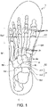
- FIG. 1 is a plan view schematically illustrating a state in which a skeleton model of a foot is overlapped on a shoe 1.
- a direction in which a shoe center axis C, which is a perpendicular line passing through the center of the shoe 1 in a plan view of the shoe 1, extends is referred to as a front-rear direction
- a direction orthogonal to the front-rear direction in a plan view of the shoe 1 is referred to as a left-right direction.
- a direction from an end on a side where a portion covering a rear foot portion of the foot of the shoe 1 is located toward an end on a side where a portion covering a front foot portion of the foot of the shoe 1 is located is referred to as a front
- a direction from the end on the side where the portion covering the front foot portion of the foot of the shoe 1 is located toward the end on the side where the portion covering the rear foot portion of the foot of the shoe 1 is located is referred to as a rear.
- a median side in an anatomical position of the foot is referred to as a medial foot side
- a side opposite to the median side in the anatomical position of the foot is referred to as a lateral foot side. That is, a side closer to a median in the anatomical position is referred to as the medial foot side, and a side farther from the median in the anatomical position is referred to as the lateral foot side.
- a height direction means a direction orthogonal to both the front-rear direction and the left-right direction unless otherwise specified
- a thickness means a dimension in the height direction unless otherwise specified.
- the foot of a human body mainly includes a cuneiform bone Ba, a cuboid bone Bb, a scaphoid bone Bc, a talus bone Bd, a calcaneus bone Be, a metatarsal bone Bf, and a phalanx bone Bg.
- Joints of the foot include an MP joint Ja, a Lisfranc joint Jb, and a Chopart joint Jc.
- the Chopart joint Jc includes a calcaneocuboid joint Jc1 formed by the cuboid bone Bb and the calcaneus bone Be, and a talonavicular joint Jc2 formed by the scaphoid bone Bc and the talus bone Bd.
- a middle foot portion of the foot refers to a portion from the MP joint Ja to the Chopart joint Jc.
- a medial longitudinal arch Ar of the foot refers to a portion from the calcaneus bone Be to a ball of the foot of a first metatarsal bone Bf1 via the talus bone Bd, the scaphoid bone Bc, and the medial cuneiform bone Ba, in the medial foot side of the foot.
- a line along the left-right direction passing through a position corresponding to 25% to 50% of a dimension in the front-rear direction of the shoe 1 from a front end of the shoe 1 is defined as a first boundary line S1
- a line along the left-right direction passing through a position corresponding to 55% to 80% of a dimension in the front-rear direction of the shoe 1 from the front end of the shoe 1 is defined as a second boundary line S2
- a portion located in front of the first boundary line S1 is a front foot portion of the shoe 1
- a portion sandwiched between the first boundary line S1 and the second boundary line S2 is a middle foot portion of the shoe 1
- a portion located in the rear from the second boundary line S2 is a rear foot portion of the shoe 1.
- the first boundary line S1 is a line substantially along the MP joint Ja of a wearer with a standard body shape
- the second boundary line S2 is a line substantially along the Chopart joint Jc of the wearer with the standard body shape.
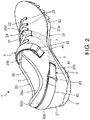
- FIG. 2 is a perspective view of the shoe 1 according to a first embodiment of the present invention.
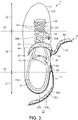
- FIG. 3 is a plan view of the shoe 1 according to the first embodiment.
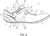
- FIG. 4 is a side view of the medial foot side of the shoe 1 according to the first embodiment.
- FIGS. 2 to 4 illustrate only the shoe 1 for the left foot. Since the shoe 1 has a bilaterally symmetrical structure for the left foot and the right foot, only the shoe 1 for the left foot will be described in the present embodiment, and the description of the shoe 1 for the right foot will be omitted.
- the shoe 1 is a spiked shoe for track and field in the present embodiment, but may be a running shoe, a shoe for sports such as soccer, basketball, volleyball, and the like.
- the shoe 1 includes an upper 2, a sole 3, an adjuster belt 4, a first support member 5, a first pulling-up member 6, and a second support member 7.
- the upper 2 includes an upper main body 20, a shoe tongue 21, and a shoelace 22.
- the upper main body 20 covers a portion on an instep side of the foot.
- a foot insertion opening 20a for inserting a foot of a wearer, and an opening 20b communicating with the foot insertion opening 20a and extending in front from the foot insertion opening 20a are formed at an upper portion of the upper main body 20.
- First string passing portions 23 and a second string passing portion 24 that are a plurality of string passing portions separated from each other in the front-rear direction are provided at left and right side edges of the opening 20b.
- the first string passing portions 23 are through holes penetrating the upper main body 20 in a vertical direction.
- One second string passing portion 24 of the plurality of string passing portions is provided at a medial foot side portion of the second support member 7.
- the second string passing portion 24 is formed by annularly folding back and stitching the medial foot side portion of the second support member 7, but may be formed by fixing an annular member separate from the second support member 7 to the medial foot side portion of the second support member 7.
- the upper main body 20 includes an upper front foot portion 25 that is a portion covering a front foot portion of the foot of the wearer with a standard body shape, an upper middle foot portion 26 that is a portion covering a middle foot portion of the foot of the wearer with the standard body shape, and an upper rear foot portion 27 that is a portion covering a heel portion of the foot of the wearer with the standard body shape.
- the upper front foot portion 25, the upper middle foot portion 26, and the upper rear foot portion 27 are connected together in this order in the front-rear direction from the front of the upper main body 20.
- the upper front foot portion 25 is located in front of the first boundary line S1.
- the upper middle foot portion 26 is located at a portion sandwiched between the first boundary line S1 and the second boundary line S2.
- the upper rear foot portion 27 is located in the rear from the second boundary line S2.
- a slit-shaped first through hole 20c and a slit-shaped second through hole 20d that communicate the inside and the outside of the upper 2 are formed in a medial foot side portion of the upper middle foot portion 26.
- the first through hole 20c is provided at a position overlapping the foot insertion opening 20a in the left-right direction.
- the second through hole 20d is provided at a position overlapping the opening 20b in the left-right direction.
- the shoe tongue 21 is a member for protecting the instep of the foot of the wearer.
- the shoe tongue 21 covers the opening 20b inside the upper main body 20.
- the shoe tongue 21 is fixed to the upper main body 20 by stitching, welding, bonding, or a combination thereof.
- a material of the upper main body 20 and the shoe tongue 21 for example, a woven fabric, a knitted fabric, synthetic leather, or resin is used.
- the materials of the upper main body 20 and the shoe tongue 21 are not limited to the exemplified materials.
- the shoelace 22 is a string-like member that alternately passes through the first string passing portions 23 and the second string passing portion 24 provided at one of the side edges of the opening 20b and the first string passing portions 23 provided at another of the side edges of the opening 20b, and is detachably attached to the upper main body 20.
- the sole 3 is located below the upper 2.
- the sole 3 covers a sole of the foot.
- the sole 3 includes an outsole 30 and a midsole 31.
- the sole 3 is fixed to the upper 2 by stitching, welding, bonding, or a combination thereof.
- a lower surface of the outsole 30 serves as a ground contact surface 30a that comes in contact with the ground.
- the midsole 31 is located on an upper surface of the outsole 30 and has a cushioning property.
- the outsole 30 may be integrated with the midsole 31.
- the outsole 30 integrated with the midsole 31 is also referred to as a "unisole".
- the sole 3 includes a footbed 8.
- the footbed 8 is placed on the outsole 30 with the midsole 31 interposed therebetween, inside the upper 2.
- the sole 3 includes an insole (not illustrated) that covers a lower opening of the upper main body 20.
- the insole is fixed to an upper surface of the midsole 31 by bonding or welding.
- the insole is fixed to a lower edge of the upper main body 20 described above by stitching.
- the footbed 8 is placed on the outsole 30 with the insole and the midsole 31 interposed therebetween.
- the sole 3 may have a structure in which the insole is omitted.
- the adjuster belt 4 is a member enabled to apply, to the upper main body 20, tightening force for pulling the medial foot side portion and a lateral foot side portion of the upper middle foot portion 26 toward each other.
- the adjuster belt 4 extends in the left-right direction across the opening 20b.
- the adjuster belt 4 is disposed near a boundary with the foot insertion opening 20a in the opening 20b in the front-rear direction.
- a fixed belt 41 and a connecting part 42 that support the adjuster belt 4 are provided in the medial foot side portion of the upper middle foot portion 26.
- the fixed belt 41 is provided at a location that is in front of the first through hole 20c and is in the rear of the second through hole 20d. A first end of the fixed belt 41 is fixed to the upper middle foot portion 26. A second end of the fixed belt 41 is connected to the connecting part 42.
- a lateral foot side portion of the adjuster belt 4 is fixed to the lateral foot side portion of the upper middle foot portion 26, the adjuster belt 4 extends from the lateral foot side portion to the medial foot side portion of the upper middle foot portion 26, and then is folded back at the connecting part 42 and extends to the lateral foot side.
- the adjuster belt 4 includes a first tightening side extending portion 4a and a second tightening side extending portion 4b.
- a lateral foot side portion of the first tightening side extending portion 4a is fixed to the lateral foot side portion of the upper middle foot portion 26.
- the first tightening side extending portion 4a extends from the lateral foot side portion toward the medial foot side portion of the upper middle foot portion 26 to the connecting part 42.
- a hook-and-loop fastener 4c is attached to a surface of the first tightening side extending portion 4a facing away from the upper middle foot portion 26.
- a hook-and-loop fastener 4d is attached to a surface of the second tightening side extending portion 4b facing the upper middle foot portion 26.
- the second tightening side extending portion 4b can be fixed to and separated from the first tightening side extending portion 4a via the hook-and-loop fasteners 4c and 4d. In a state in which the second tightening side extending portion 4b is fixed to the first tightening side extending portion 4a, the second tightening side extending portion 4b extends from the connecting part 42 to the lateral foot side portion of the upper middle foot portion 26.
- the connecting part 42 connects the second end of the fixed belt 41 and a folded portion of the adjuster belt 4 to each other.
- a configuration of the connecting part 42 is not particularly limited as long as the fixed belt 41 and the adjuster belt 4 can be connected to each other, but is a ring-shaped member in the present embodiment.
- the second end of the fixed belt 41 passes through the connecting part 42 and is folded back, and overlapping portions of the fixed belt 41 are stitched together, whereby the fixed belt 41 is connected to the connecting part 42.
- FIG. 5 is a plan view schematically illustrating an outer shape of the shoe 1 and the first support member 5 and the second support member 7.
- FIG. 6 is a cross-sectional view taken along line VI-VI illustrated in FIG. 4 , and is a cross-sectional view illustrating a state before the first support member 5 is pulled up.
- FIG. 7 is a cross-sectional view illustrating a state after the first support member 5 is pulled up from the state illustrated in FIG. 6 .
- FIG. 8 is a perspective view schematically illustrating a state in which the first support member 5 is overlapped on a foot F. As illustrated in FIG.
- the first support member 5 is a member disposed below the medial longitudinal arch Ar of the foot F inside the upper 2, and its lateral foot side portion is fixed to the upper main body 20.
- the first support member 5 is disposed below the entire foot F including the medial longitudinal arch Ar.
- the first support member 5 is disposed in the upper middle foot portion 26.
- the first support member 5 may be fixed to the footbed 8 or the insole of the sole 3.
- the first support member 5 is fixed to any of the upper main body 20, the footbed 8, and the insole by stitching, welding, bonding, or a combination thereof.
- a material of the first support member 5 for example, a woven fabric, a knitted fabric, synthetic leather, or resin is used. As illustrated in FIG.
- a plan view shape of the first support member 5 is not particularly limited, but is a trapezoidal shape in the present embodiment.
- a front end portion, a rear end portion, and a medial foot side end portion of the first support member 5 have a curved shape in the present embodiment, but may have, for example, a linear shape, a waveform shape, or a jagged shape.
- the first pulling-up member 6 is a member connected to a medial foot side portion of the first support member 5 and enabled to apply, to the first support member 5, force for pulling up the first support member 5 in a direction toward the upper rear foot portion 27 and away from the sole 3.
- the first pulling-up member 6 extends along an extending direction of a tibialis posterior tendon Te of the foot F of the wearer, and is enabled to apply, to the first support member 5, force for pulling up the first support member 5 along the tibialis posterior tendon Te.
- the first pulling-up member 6 is enabled to apply, to the first support member 5, force for pulling up the first support member 5 obliquely upward and in the rear.
- the first pulling-up member 6 passes through the medial foot side portion of the upper middle foot portion 26 from the inside to the outside of the upper 2, and extends from the medial foot side to the lateral foot side along the upper rear foot portion 27 and is fixable to the upper rear foot portion 27.
- "a state in which the first pulling-up member 6 extends along the upper rear foot portion 27” means "a state in which the first pulling-up member 6 extends along the extending direction of the tibialis posterior tendon Te of the foot F of the wearer".
- the first pulling-up member 6 includes a first belt 61, a second belt 62, and a coupling part 63.
- a material of the first belt 61 and the second belt 62 for example, a woven fabric, a knitted fabric, synthetic leather, or resin is used.
- the first belt 61 is connected to the medial foot side portion of the first support member 5 inside the upper 2, and passes through the medial foot side portion of the upper middle foot portion 26 from the inside to the outside of the upper 2. A part of the first belt 61 is exposed to the outside of the upper 2 through the first through hole 20c.
- the first belt 61 is fixed to the first support member 5 by stitching, for example.
- a lateral foot side portion of the second belt 62 is fixed to a lateral foot side portion of the upper rear foot portion 27, the second belt 62 extends from the lateral foot side to the medial foot side along the upper rear foot portion 27, and then is folded back at the coupling part 63 and extends to the lateral foot side.
- the second belt 62 includes a first pulling-up side extending portion 62a and a second pulling-up side extending portion 62b.
- a lateral foot side portion of the first pulling-up side extending portion 62a is fixed to the lateral foot side portion of the upper rear foot portion 27.
- the first pulling-up side extending portion 62a extends from the lateral foot side toward the medial foot side to the coupling part 63 along the upper rear foot portion 27.
- a hook-and-loop fastener 62c is attached to a surface of the first pulling-up side extending portion 62a facing away from the upper rear foot portion 27.
- a hook-and-loop fastener 62d is attached to a surface of the second pulling-up side extending portion 62b facing the upper rear foot portion 27.
- the second pulling-up side extending portion 62b can be fixed to and separated from the first pulling-up side extending portion 62a via the hook-and-loop fasteners 62c and 62d.
- the second pulling-up side extending portion 62b In a state in which the second pulling-up side extending portion 62b is fixed to the first pulling-up side extending portion 62a, the second pulling-up side extending portion 62b extends from the coupling part 63 to the lateral foot side portion of the upper rear foot portion 27.
- the coupling part 63 couples an end portion of the first belt 61 exposed to the outside of the upper 2 and a folded portion of the second belt 62 to each other.
- a configuration of the coupling part 63 is not particularly limited as long as the first belt 61 and the second belt 62 can be coupled together, but is a ring-shaped member in the present embodiment.
- the end portion of the first belt 61 exposed to the outside of the upper 2 passes through the coupling part 63 and is folded back, and overlapping portions of the first belt 61 are stitched together, whereby the first belt 61 is coupled to the coupling part 63.
- FIG. 9 is a cross-sectional view taken along line IX-IX illustrated in FIG. 4 , and is a cross-sectional view illustrating a state before the second support member 7 is pulled up.
- FIG. 10 is a cross-sectional view illustrating a state after the second support member 7 is pulled up from the state illustrated in FIG. 9 .
- FIG. 11 is a perspective view schematically illustrating a state in which the second support member 7 is overlapped on the foot F.
- the second support member 7 is disposed in front of the first support member 5 inside the upper 2 and below the medial longitudinal arch Ar, and its lateral foot side portion is fixed to the upper main body 20.
- FIG. 9 is a cross-sectional view taken along line IX-IX illustrated in FIG. 4 , and is a cross-sectional view illustrating a state before the second support member 7 is pulled up.
- FIG. 10 is a cross-sectional view illustrating a state after the second support member 7 is pulled up from the state illustrated in FIG. 9
- the second support member 7 is disposed below the entire foot F including the medial longitudinal arch Ar.
- the second support member 7 is disposed in the upper middle foot portion 26.
- the second support member 7 may be fixed to the footbed 8 or the insole of the sole 3 illustrated in FIG. 9 .
- the second support member 7 is fixed to any of the upper main body 20, the footbed 8, and the insole by stitching, welding, bonding, or a combination thereof.
- a plan view shape of the second support member 7 is not particularly limited, but is a trapezoidal shape in the present embodiment.
- a front end portion, a rear end portion, and a medial foot side end portion of the second support member 7 have a curved shape in the present embodiment, but may have, for example, a linear shape, a waveform shape, or a jagged shape.
- the shoelace 22 is a second pulling-up member connected to the medial foot side portion of the second support member 7 and enabled to apply, to the second support member 7, force for pulling up the second support member 7 in the normal direction of the medial longitudinal arch Ar.
- the shoelace 22 is enabled to apply, to the second support member 7, force for pulling up the second support member 7 in a direction in which the second support member 7 is separated from the sole 3.
- the shoelace 22 is enabled to apply, to the second support member 7, force for pulling up the second support member 7 upward.
- the shoelace 22 when the shoelace 22 is tensioned, the second string passing portion 24 is pulled upward and toward the lateral foot side, and the second support member 7 is pulled up in the normal direction of the medial longitudinal arch Ar to be separated from the sole 3.
- the shoe 1 includes: the first support member 5 disposed below the medial longitudinal arch Ar of the foot F inside the upper 2 and including the lateral foot side portion fixed to the upper 2; and the first pulling-up member 6 connected to the medial foot side portion of the first support member 5 and enabled to apply, to the first support member 5, the force for pulling up the first support member 5 in the direction toward the upper rear foot portion 27 and away from the sole 3.
- the first support member 5 is pulled up in the direction toward the upper rear foot portion 27 and away from the sole 3, so that falling of the medial longitudinal arch Ar of the foot F can be suppressed.
- the shoe 1 includes: the second support member 7 disposed in front of the first support member 5 inside the upper 2 and disposed below the medial longitudinal arch Ar, and including the lateral foot side portion fixed to the upper 2; and the shoelace 22 connected to the medial foot side portion of the second support member 7 and enabled to apply, to the second support member 7, the force for pulling up the second support member 7 in the normal direction of the medial longitudinal arch Ar.
- the first pulling-up member 6 includes: the first belt 61 connected to the medial foot side portion of the first support member 5 and passing through the medial foot side portion of the upper middle foot portion 26 from the inside to the outside of the upper 2; the second belt 62 including the lateral foot side portion fixed to the lateral foot side portion of the upper rear foot portion 27, extending from the lateral foot side to the medial foot side along the upper rear foot portion 27, and then folded back and extending to the lateral foot side; and the coupling part 63 that couples the first belt 61 and the folded portion of the second belt 62 to each other.
- the first pulling-up member 6 has a structure independent of the shoelace 22 and the adjuster belt 4, a degree of pulling-up of the first support member 5 can be independently adjusted without considering a degree of tightening of the upper main body 20.
- one second string passing portion 24 of the plurality of string passing portions is provided at the medial foot side portion of the second support member 7, and the shoelace 22 alternately passes through the first string passing portions 23 and the second string passing portion 24 provided at one of the side edges of the opening 20b and the first string passing portions 23 provided at another of the side edges of the opening 20b.
- the width of the first support member 5 in the front-rear direction increases from the connection portion with the first pulling-up member 6 toward the lateral foot side, so that it is possible to alleviate contact of the first support member 5 with the foot F of the wearer. That is, since a contact area between the foot F of the wearer and the shoe 1 increases toward the lateral foot side, it is possible to alleviate the contact of the first support member 5 with the foot F of the wearer by increasing a contact area between the foot F and the first support member 5 toward the lateral foot side.
- the width of the second support member 7 in the front-rear direction increases from the connection portion with the shoelace 22 illustrated in FIG.
- the sole 3 includes the outsole 30 and the footbed 8 placed on the outsole 30 inside the upper 2, and the first support member 5 and the second support member 7 are arranged on the footbed 8.
- the first support member 5 and the second support member 7 can be directly brought into contact with the foot F, and the first support member 5 and the second support member 7 can be deformed along a shape of the foot F of each wearer.
- the first support member 5 and the second support member 7 can therefore be favorably brought into contact with the foot F of the wearer.
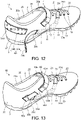
- FIG. 12 is a perspective view of a shoe 1A according to a second embodiment of the present invention.
- the shoe 1A according to the second embodiment is different from the shoe 1 according to the first embodiment in a configuration of a first pulling-up member 6A.
- the same reference numerals are given to portions overlapping with the first embodiment described above, and description thereof is omitted.
- the first pulling-up member 6A passes through the medial foot side portion of the upper middle foot portion 26 from the inside to the outside of the upper 2, and extends along the upper rear foot portion 27 and is fixable to the upper rear foot portion 27.
- the first pulling-up member 6A includes one belt 64a and a belt fixing portion 64b.
- a material of the belt 64a and the belt fixing portion 64b for example, a woven fabric, a knitted fabric, synthetic leather, or resin is used.
- the belt 64a is connected to the medial foot side portion of the first support member 5 inside the upper 2, and passes through the medial foot side portion of the upper middle foot portion 26 from the inside to the outside of the upper 2. A part of the belt 64a is exposed to the outside of the upper 2 through the first through hole 20c.
- the belt 64a is fixed to the first support member 5 by stitching, for example.
- a hook-and-loop fastener 64c is attached to a surface of the belt 64a facing the upper rear foot portion 27.
- the belt fixing portion 64b is fixed to the upper rear foot portion 27 and extends in the left-right direction along the upper rear foot portion 27.
- a hook-and-loop fastener 64d is attached to a surface of the belt fixing portion 64b facing away from the upper rear foot portion 27.
- the belt 64a can be fixed to and separated from the belt fixing portion 64b via the hook-and-loop fasteners 64c and 64d. In a state in which the belt 64a is fixed to the belt fixing portion 64b, the belt 64a extends from the medial foot side to the lateral foot side along the upper rear foot portion 27.
- the present embodiment can have effects similar to those of the first embodiment described above. Note that the first support member 5 and the belt 64a may be integrally formed.
- FIG. 13 is a perspective view of a shoe 1B according to a third embodiment of the present invention.
- FIG. 14 is a plan view of the shoe 1B according to the third embodiment.
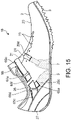
- FIG. 15 is a side view of the medial foot side of the shoe 1B according to the third embodiment.
- the shoe 1B according to the third embodiment is different from the shoe 1 according to the first embodiment in a configuration of a first pulling-up member 6B. Note that, in the third embodiment, the same reference numerals are given to portions overlapping with the first embodiment described above, and description thereof is omitted.
- the first pulling-up member 6B includes a first belt 65a, a second belt 65b, a fixed belt 65c, a connecting part 65d, and a coupling part 65e.
- the fixed belt 65c and the connecting part 65d are located obliquely above and in the rear from the first through hole 20c, in the medial foot side portion of the upper middle foot portion 26.
- the coupling part 65e is located obliquely upward and in front from the first through hole 20c and in the rear from the second through hole 20d, in the medial foot side portion of the upper middle foot portion 26.
- the first belt 65a is connected to the medial foot side portion of the first support member 5 inside the upper 2, and passes through the medial foot side portion of the upper middle foot portion 26 from the inside to the outside of the upper 2. A part of the first belt 65a is exposed to the outside of the upper 2 through the first through hole 20c. The first belt 65a extends from the first through hole 20c toward the connecting part 65d, is then folded back at the connecting part 65d, and extends toward the coupling part 65e. A portion of the first belt 65a from the first through hole 20c to the connecting part 65d extends along the extending direction of the tibialis posterior tendon Te illustrated in FIG. 8 .
- the outer layer of the upper main body 20 serves as a deflection suppressing portion 65f that suppresses deflection of the first belt 65a toward the medial foot side.
- a first end of the fixed belt 65c is fixed to the upper middle foot portion 26.
- a second end of the fixed belt 65c is connected to the connecting part 65d.
- the connecting part 65d connects the second end of the fixed belt 65c and a folded portion of the first belt 65a to each other.
- a configuration of the connecting part 65d is not particularly limited as long as the fixed belt 65c and the first belt 65a can be connected to each other, but is a ring-shaped member in the present embodiment.
- the second end of the fixed belt 65c is passed through the connecting part 65d and folded back, and overlapping portions of the fixed belt 65c are stitched together, whereby the fixed belt 65c is connected to the connecting part 65d.
- the second belt 65b is a member corresponding to the adjuster belt 4 of the first embodiment described above.
- the second belt 65b is enabled to apply, to the upper main body 20, tightening force for pulling the medial foot side portion and the lateral foot side portion of the upper middle foot portion 26 toward each other.
- the lateral foot side portion of the second belt 65b is fixed to the lateral foot side portion of the upper middle foot portion 26,
- the second belt 65b extends from the lateral foot side portion to the medial foot side portion of the upper middle foot portion 26, and then is folded back at the coupling part 65e and extends to the lateral foot side.
- the second belt 65b includes a first extending portion 65g and a second extending portion 65h.
- a lateral foot side portion of the first extending portion 65g is fixed to the lateral foot side portion of the upper middle foot portion 26.
- the first extending portion 65g extends from the lateral foot side portion toward the medial foot side portion of the upper middle foot portion 26 to the coupling part 65e.
- a hook-and-loop fastener 65i is attached to a surface of the first extending portion 65g facing away from the upper middle foot portion 26.
- a hook-and-loop fastener 65j is attached to a surface of the second extending portion 65h facing the upper middle foot portion 26.
- the second extending portion 65h can be fixed to and separated from the first extending portion 65g via the hook-and-loop fasteners 65i and 65j. In a state in which the second extending portion 65h is fixed to the first extending portion 65g, the second extending portion 65h extends from the coupling part 65e to the lateral foot side portion of the upper middle foot portion 26.
- the coupling part 65e couples an end portion of the first belt 65a exposed to the outside of the upper 2 and a folded portion of the second belt 65b to each other.
- a configuration of the coupling part 65e is not particularly limited as long as the first belt 65a and the second belt 65b can be coupled together, but is a ring-shaped member in the present embodiment.
- the end portion of the first belt 65a exposed to the outside of the upper 2 passes through the coupling part 65e and is folded back, and overlapping portions of the first belt 65a are stitched together, whereby the first belt 65a is coupled to the coupling part 65e.
- the first pulling-up member 6B includes the first belt 65a connected to the medial foot side portion of the first support member 5 and passing through the medial foot side portion of the upper middle foot portion 26 from the inside to the outside of the upper 2.
- the first pulling-up member 6B includes the second belt 65b including the lateral foot side portion fixed to the lateral foot side portion of the upper middle foot portion 26, extending from the lateral foot side portion to the medial foot side portion of the upper middle foot portion 26, and then folded back and extending to the lateral foot side.
- the second belt 65b is enabled to apply, to the upper 2, tightening force for pulling the medial foot side portion and the lateral foot side portion of the upper middle foot portion 26 toward each other.
- the first pulling-up member 6B includes the coupling part 65e that couples the first belt 65a and the folded portion of the second belt 65b to each other.
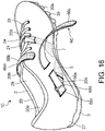
- FIG. 16 is a perspective view of a shoe 1C according to a fourth embodiment of the present invention.
- the shoe 1C according to the fourth embodiment is different from the shoe 1B according to the third embodiment in a configuration of a first pulling-up member 6C.
- the same reference numerals are given to portions overlapping with the third embodiment described above, and description thereof is omitted.
- the first pulling-up member 6C passes through the medial foot side portion of the upper middle foot portion 26 from the inside to the outside of the upper 2, extends from the medial foot side portion to the lateral foot side portion of the upper middle foot portion 26, and is fixable to the upper middle foot portion 26.
- the first pulling-up member 6C includes one belt 66a, the fixed belt 65c, the connecting part 65d, and a belt fixing portion 66b. Configurations of the fixed belt 65c and the connecting part 65d are similar to those of the third embodiment described above.
- the belt 66a is connected to the medial foot side portion of the first support member 5 inside the upper 2, and passes through the medial foot side portion of the upper middle foot portion 26 from the inside to the outside of the upper 2. A part of the belt 66a is exposed to the outside of the upper 2 through the first through hole 20c. The belt 66a extends from the first through hole 20c toward the connecting part 65d, is then folded back at the connecting part 65d, and extends toward the belt fixing portion 66b. A portion of the belt 66a from the first through hole 20c to the connecting part 65d extends along the extending direction of the tibialis posterior tendon Te illustrated in FIG. 8 . A hook-and-loop fastener 66c is attached to a surface of the belt 66a facing the upper middle foot portion 26.
- the belt fixing portion 66b is fixed to the upper middle foot portion 26, and extends in the left-right direction across the opening 20b in the upper middle foot portion 26.
- a hook-and-loop fastener 66d is attached to a surface of the belt fixing portion 66b facing away from the upper middle foot portion 26.
- the belt 66a can be fixed to and separated from the belt fixing portion 66b via the hook-and-loop fasteners 66c and 66d. In a state in which the belt 66a is fixed to the belt fixing portion 66b, the belt 66a extends from the medial foot side portion to the lateral foot side portion of the upper middle foot portion 26.
- the present embodiment can have effects similar to those of the first and third embodiments described above. Note that, the first support member 5 and the belt 66a may be integrally formed.
- the configuration described in each of the above embodiments illustrates an example of the content of the present invention, and can be combined with another known technique, and a part of the configuration can be omitted or changed without departing from the gist of the present invention.
- the second support member 7 is included, but may be omitted. In a case where the second support member 7 is omitted, the size of the first support member 5 may be larger than the illustrated example.
- the first support member 5 and the second support member 7 are arranged on the footbed 8, but may be arranged under the footbed 8.
- the shoe according to the present invention has an effect of reducing the burden on the tibialis posterior tendon while suppressing the falling of the medial longitudinal arch.
Landscapes
- Health & Medical Sciences (AREA)
- General Health & Medical Sciences (AREA)
- Public Health (AREA)
- Epidemiology (AREA)
- Life Sciences & Earth Sciences (AREA)
- Nursing (AREA)
- Orthopedic Medicine & Surgery (AREA)
- Engineering & Computer Science (AREA)
- Biomedical Technology (AREA)
- Heart & Thoracic Surgery (AREA)
- Vascular Medicine (AREA)
- Animal Behavior & Ethology (AREA)
- Veterinary Medicine (AREA)
- Rheumatology (AREA)
- Diabetes (AREA)
- Footwear And Its Accessory, Manufacturing Method And Apparatuses (AREA)
Abstract
Description
- The present invention relates to a shoe including an upper and a sole.
- Medial tibial stress syndrome, so-called shin splint, is conventionally known that causes inflammation in a periosteum attached to a tibia by repeatedly performing motions such as running and jumping. The shin splint is classified into two types, an "anterior shin splint" in which inflammation occurs in a periosteum between a tibialis anterior tendon and a tibia due to excessive contraction of the tibialis anterior tendon, and a "posterior shin splint" in which inflammation occurs in a periosteum between a tibialis posterior tendon and a tibia due to excessive extension of the tibialis posterior tendon. It has been found that one of causes of occurrence of the posterior shin splint is falling of a medial longitudinal arch when a wearer's weight is applied to the wearer's foot.
- Many techniques have conventionally been developed in which a reinforcing member is disposed inside an upper to suppress falling of the medial longitudinal arch by the reinforcing member, as in
JP 2016-36703 A - Thus, it is desired to develop a shoe that can reduce the burden on the tibialis posterior tendon.
- The present invention has been made in view of the above, and an object of the present invention is to obtain a shoe that can reduce the burden on the tibialis posterior tendon while suppressing the falling of the medial longitudinal arch.
- In order to solve the above-described problem and achieve the object, a shoe according to the present invention includes an upper in which an upper middle foot portion covering a middle foot portion of a foot of a wearer, an upper rear foot portion covering a heel portion of the foot, and a foot insertion opening for inserting the foot are formed, a sole located below the upper, a first support member disposed below a medial longitudinal arch of the foot inside the upper and including a lateral foot side portion fixed to the upper or the sole, and a first pulling-up member connected to a medial foot side portion of the first support member and enabled to apply, to the first support member, force for pulling up the first support member in a direction toward the upper rear foot portion and away from the sole.
-
-
FIG. 1 is a plan view schematically illustrating a state in which a skeleton model of a foot is overlapped on a shoe; -
FIG. 2 is a perspective view of the shoe according to a first embodiment of the present invention; -
FIG. 3 is a plan view of the shoe according to the first embodiment; -
FIG. 4 is a side view of a medial foot side of the shoe according to the first embodiment; -
FIG. 5 is a plan view schematically illustrating an outer shape of the shoe and a first support member and a second support member; -
FIG. 6 is a cross-sectional view taken along line VI-VI illustrated inFIG. 4 , and is a cross-sectional view illustrating a state before the first support member is pulled up; -
FIG. 7 is a cross-sectional view illustrating a state after the first support member is pulled up from the state illustrated inFIG. 6 ; -
FIG. 8 is a perspective view schematically illustrating a state in which the first support member is overlapped on a foot; -
FIG. 9 is a cross-sectional view taken along line IX-IX illustrated inFIG. 4 , and is a cross-sectional view illustrating a state before the second support member is pulled up; -
FIG. 10 is a cross-sectional view illustrating a state after the second support member is pulled up from the state illustrated inFIG. 9 ; -
FIG. 11 is a perspective view schematically illustrating a state in which the second support member is overlapped on the foot; -
FIG. 12 is a perspective view of a shoe according to a second embodiment of the present invention; -
FIG. 13 is a perspective view of a shoe according to a third embodiment of the present invention; -
FIG. 14 is a plan view of the shoe according to the third embodiment; -
FIG. 15 is a side view of a medial foot side of the shoe according to the third embodiment; and -
FIG. 16 is a perspective view of a shoe according to a fourth embodiment of the present invention. - Hereinafter, examples of a shoe according to the present invention will be described in detail with reference to the drawings. Note that the present invention is not limited by the examples.
-
FIG. 1 is a plan view schematically illustrating a state in which a skeleton model of a foot is overlapped on ashoe 1. In embodiments described below, a direction in which a shoe center axis C, which is a perpendicular line passing through the center of theshoe 1 in a plan view of theshoe 1, extends is referred to as a front-rear direction, and a direction orthogonal to the front-rear direction in a plan view of theshoe 1 is referred to as a left-right direction. - In addition, in the front-rear direction, a direction from an end on a side where a portion covering a rear foot portion of the foot of the
shoe 1 is located toward an end on a side where a portion covering a front foot portion of the foot of theshoe 1 is located is referred to as a front, and in the front-rear direction, a direction from the end on the side where the portion covering the front foot portion of the foot of theshoe 1 is located toward the end on the side where the portion covering the rear foot portion of the foot of theshoe 1 is located is referred to as a rear. - In addition, a median side in an anatomical position of the foot is referred to as a medial foot side, and a side opposite to the median side in the anatomical position of the foot is referred to as a lateral foot side. That is, a side closer to a median in the anatomical position is referred to as the medial foot side, and a side farther from the median in the anatomical position is referred to as the lateral foot side.
- In addition, a height direction means a direction orthogonal to both the front-rear direction and the left-right direction unless otherwise specified, and a thickness means a dimension in the height direction unless otherwise specified.
- The foot of a human body mainly includes a cuneiform bone Ba, a cuboid bone Bb, a scaphoid bone Bc, a talus bone Bd, a calcaneus bone Be, a metatarsal bone Bf, and a phalanx bone Bg. Joints of the foot include an MP joint Ja, a Lisfranc joint Jb, and a Chopart joint Jc. The Chopart joint Jc includes a calcaneocuboid joint Jc1 formed by the cuboid bone Bb and the calcaneus bone Be, and a talonavicular joint Jc2 formed by the scaphoid bone Bc and the talus bone Bd.
- A middle foot portion of the foot refers to a portion from the MP joint Ja to the Chopart joint Jc. A medial longitudinal arch Ar of the foot refers to a portion from the calcaneus bone Be to a ball of the foot of a first metatarsal bone Bf1 via the talus bone Bd, the scaphoid bone Bc, and the medial cuneiform bone Ba, in the medial foot side of the foot.
- In addition, in a case where a line along the left-right direction passing through a position corresponding to 25% to 50% of a dimension in the front-rear direction of the
shoe 1 from a front end of theshoe 1 is defined as a first boundary line S1, and a line along the left-right direction passing through a position corresponding to 55% to 80% of a dimension in the front-rear direction of theshoe 1 from the front end of theshoe 1 is defined as a second boundary line S2, a portion located in front of the first boundary line S1 is a front foot portion of theshoe 1, a portion sandwiched between the first boundary line S1 and the second boundary line S2 is a middle foot portion of theshoe 1, and a portion located in the rear from the second boundary line S2 is a rear foot portion of theshoe 1. The first boundary line S1 is a line substantially along the MP joint Ja of a wearer with a standard body shape, and the second boundary line S2 is a line substantially along the Chopart joint Jc of the wearer with the standard body shape. -
FIG. 2 is a perspective view of theshoe 1 according to a first embodiment of the present invention.FIG. 3 is a plan view of theshoe 1 according to the first embodiment.FIG. 4 is a side view of the medial foot side of theshoe 1 according to the first embodiment.FIGS. 2 to 4 illustrate only theshoe 1 for the left foot. Since theshoe 1 has a bilaterally symmetrical structure for the left foot and the right foot, only theshoe 1 for the left foot will be described in the present embodiment, and the description of theshoe 1 for the right foot will be omitted. - The
shoe 1 is a spiked shoe for track and field in the present embodiment, but may be a running shoe, a shoe for sports such as soccer, basketball, volleyball, and the like. Theshoe 1 includes an upper 2, a sole 3, anadjuster belt 4, afirst support member 5, a first pulling-upmember 6, and asecond support member 7. - The upper 2 includes an upper
main body 20, ashoe tongue 21, and ashoelace 22. - The upper
main body 20 covers a portion on an instep side of the foot. A foot insertion opening 20a for inserting a foot of a wearer, and an opening 20b communicating with the foot insertion opening 20a and extending in front from the foot insertion opening 20a are formed at an upper portion of the uppermain body 20. Firststring passing portions 23 and a secondstring passing portion 24 that are a plurality of string passing portions separated from each other in the front-rear direction are provided at left and right side edges of the opening 20b. The firststring passing portions 23 are through holes penetrating the uppermain body 20 in a vertical direction. One secondstring passing portion 24 of the plurality of string passing portions is provided at a medial foot side portion of thesecond support member 7. In the present embodiment, the secondstring passing portion 24 is formed by annularly folding back and stitching the medial foot side portion of thesecond support member 7, but may be formed by fixing an annular member separate from thesecond support member 7 to the medial foot side portion of thesecond support member 7. - As illustrated in
FIG. 3 , the uppermain body 20 includes an upperfront foot portion 25 that is a portion covering a front foot portion of the foot of the wearer with a standard body shape, an uppermiddle foot portion 26 that is a portion covering a middle foot portion of the foot of the wearer with the standard body shape, and an upperrear foot portion 27 that is a portion covering a heel portion of the foot of the wearer with the standard body shape. The upperfront foot portion 25, the uppermiddle foot portion 26, and the upperrear foot portion 27 are connected together in this order in the front-rear direction from the front of the uppermain body 20. The upperfront foot portion 25 is located in front of the first boundary line S1. The uppermiddle foot portion 26 is located at a portion sandwiched between the first boundary line S1 and the second boundary line S2. The upperrear foot portion 27 is located in the rear from the second boundary line S2. - As illustrated in
FIG. 2 , a slit-shaped first throughhole 20c and a slit-shaped second throughhole 20d that communicate the inside and the outside of the upper 2 are formed in a medial foot side portion of the uppermiddle foot portion 26. The first throughhole 20c is provided at a position overlapping thefoot insertion opening 20a in the left-right direction. The second throughhole 20d is provided at a position overlapping theopening 20b in the left-right direction. - As illustrated in
FIG. 3 , theshoe tongue 21 is a member for protecting the instep of the foot of the wearer. Theshoe tongue 21 covers theopening 20b inside the uppermain body 20. Theshoe tongue 21 is fixed to the uppermain body 20 by stitching, welding, bonding, or a combination thereof. As a material of the uppermain body 20 and theshoe tongue 21, for example, a woven fabric, a knitted fabric, synthetic leather, or resin is used. In particular, in theshoe 1 in which air permeability and a lightweight property are required, it is preferable to use a double raschel warp knitted fabric knitted with polyester yarn as the material of the uppermain body 20 and theshoe tongue 21. Note that the materials of the uppermain body 20 and theshoe tongue 21 are not limited to the exemplified materials. - The
shoelace 22 is a string-like member that alternately passes through the firststring passing portions 23 and the secondstring passing portion 24 provided at one of the side edges of theopening 20b and the firststring passing portions 23 provided at another of the side edges of theopening 20b, and is detachably attached to the uppermain body 20. - As illustrated in
FIG. 2 , the sole 3 is located below the upper 2. The sole 3 covers a sole of the foot. The sole 3 includes anoutsole 30 and amidsole 31. The sole 3 is fixed to the upper 2 by stitching, welding, bonding, or a combination thereof. A lower surface of theoutsole 30 serves as aground contact surface 30a that comes in contact with the ground. Themidsole 31 is located on an upper surface of theoutsole 30 and has a cushioning property. Note that theoutsole 30 may be integrated with themidsole 31. Theoutsole 30 integrated with themidsole 31 is also referred to as a "unisole". In addition, as illustrated inFIG. 3 , the sole 3 includes afootbed 8. Thefootbed 8 is placed on theoutsole 30 with themidsole 31 interposed therebetween, inside the upper 2. - The sole 3 includes an insole (not illustrated) that covers a lower opening of the upper
main body 20. The insole is fixed to an upper surface of themidsole 31 by bonding or welding. In addition, the insole is fixed to a lower edge of the uppermain body 20 described above by stitching. In a case where the sole 3 includes the insole, thefootbed 8 is placed on theoutsole 30 with the insole and themidsole 31 interposed therebetween. Note that the sole 3 may have a structure in which the insole is omitted. - As illustrated in
FIG. 2 , theadjuster belt 4 is a member enabled to apply, to the uppermain body 20, tightening force for pulling the medial foot side portion and a lateral foot side portion of the uppermiddle foot portion 26 toward each other. Theadjuster belt 4 extends in the left-right direction across theopening 20b. Theadjuster belt 4 is disposed near a boundary with thefoot insertion opening 20a in theopening 20b in the front-rear direction. A fixedbelt 41 and a connectingpart 42 that support theadjuster belt 4 are provided in the medial foot side portion of the uppermiddle foot portion 26. - In the medial foot side portion of the upper
middle foot portion 26, the fixedbelt 41 is provided at a location that is in front of the first throughhole 20c and is in the rear of the second throughhole 20d. A first end of the fixedbelt 41 is fixed to the uppermiddle foot portion 26. A second end of the fixedbelt 41 is connected to the connectingpart 42. - As illustrated in
FIG. 3 , a lateral foot side portion of theadjuster belt 4 is fixed to the lateral foot side portion of the uppermiddle foot portion 26, theadjuster belt 4 extends from the lateral foot side portion to the medial foot side portion of the uppermiddle foot portion 26, and then is folded back at the connectingpart 42 and extends to the lateral foot side. Theadjuster belt 4 includes a first tighteningside extending portion 4a and a second tightening side extending portion 4b. A lateral foot side portion of the first tighteningside extending portion 4a is fixed to the lateral foot side portion of the uppermiddle foot portion 26. The first tighteningside extending portion 4a extends from the lateral foot side portion toward the medial foot side portion of the uppermiddle foot portion 26 to the connectingpart 42. A hook-and-loop fastener 4c is attached to a surface of the first tighteningside extending portion 4a facing away from the uppermiddle foot portion 26. A hook-and-loop fastener 4d is attached to a surface of the second tightening side extending portion 4b facing the uppermiddle foot portion 26. The second tightening side extending portion 4b can be fixed to and separated from the first tighteningside extending portion 4a via the hook-and-loop fasteners side extending portion 4a, the second tightening side extending portion 4b extends from the connectingpart 42 to the lateral foot side portion of the uppermiddle foot portion 26. - As illustrated in
FIG. 2 , the connectingpart 42 connects the second end of the fixedbelt 41 and a folded portion of theadjuster belt 4 to each other. A configuration of the connectingpart 42 is not particularly limited as long as the fixedbelt 41 and theadjuster belt 4 can be connected to each other, but is a ring-shaped member in the present embodiment. In the present embodiment, the second end of the fixedbelt 41 passes through the connectingpart 42 and is folded back, and overlapping portions of the fixedbelt 41 are stitched together, whereby the fixedbelt 41 is connected to the connectingpart 42. -
FIG. 5 is a plan view schematically illustrating an outer shape of theshoe 1 and thefirst support member 5 and thesecond support member 7.FIG. 6 is a cross-sectional view taken along line VI-VI illustrated inFIG. 4 , and is a cross-sectional view illustrating a state before thefirst support member 5 is pulled up.FIG. 7 is a cross-sectional view illustrating a state after thefirst support member 5 is pulled up from the state illustrated inFIG. 6 .FIG. 8 is a perspective view schematically illustrating a state in which thefirst support member 5 is overlapped on a foot F. As illustrated inFIG. 6 , thefirst support member 5 is a member disposed below the medial longitudinal arch Ar of the foot F inside the upper 2, and its lateral foot side portion is fixed to the uppermain body 20. Thefirst support member 5 is disposed below the entire foot F including the medial longitudinal arch Ar. Thefirst support member 5 is disposed in the uppermiddle foot portion 26. Note that thefirst support member 5 may be fixed to thefootbed 8 or the insole of the sole 3. Thefirst support member 5 is fixed to any of the uppermain body 20, thefootbed 8, and the insole by stitching, welding, bonding, or a combination thereof. As a material of thefirst support member 5, for example, a woven fabric, a knitted fabric, synthetic leather, or resin is used. As illustrated inFIG. 5 , the width of thefirst support member 5 in the front-rear direction increases from a connection portion with the first pulling-upmember 6 toward the lateral foot side. A plan view shape of thefirst support member 5 is not particularly limited, but is a trapezoidal shape in the present embodiment. A front end portion, a rear end portion, and a medial foot side end portion of thefirst support member 5 have a curved shape in the present embodiment, but may have, for example, a linear shape, a waveform shape, or a jagged shape. - As illustrated in
FIG. 7 , the first pulling-upmember 6 is a member connected to a medial foot side portion of thefirst support member 5 and enabled to apply, to thefirst support member 5, force for pulling up thefirst support member 5 in a direction toward the upperrear foot portion 27 and away from the sole 3. In other words, as illustrated inFIG. 8 , the first pulling-upmember 6 extends along an extending direction of a tibialis posterior tendon Te of the foot F of the wearer, and is enabled to apply, to thefirst support member 5, force for pulling up thefirst support member 5 along the tibialis posterior tendon Te. In yet other words, the first pulling-upmember 6 is enabled to apply, to thefirst support member 5, force for pulling up thefirst support member 5 obliquely upward and in the rear. As illustrated inFIG. 2 , the first pulling-upmember 6 passes through the medial foot side portion of the uppermiddle foot portion 26 from the inside to the outside of the upper 2, and extends from the medial foot side to the lateral foot side along the upperrear foot portion 27 and is fixable to the upperrear foot portion 27. Note that, in the present specification, "a state in which the first pulling-upmember 6 extends along the upperrear foot portion 27" means "a state in which the first pulling-upmember 6 extends along the extending direction of the tibialis posterior tendon Te of the foot F of the wearer". The first pulling-upmember 6 includes afirst belt 61, asecond belt 62, and acoupling part 63. As a material of thefirst belt 61 and thesecond belt 62, for example, a woven fabric, a knitted fabric, synthetic leather, or resin is used. - The
first belt 61 is connected to the medial foot side portion of thefirst support member 5 inside the upper 2, and passes through the medial foot side portion of the uppermiddle foot portion 26 from the inside to the outside of the upper 2. A part of thefirst belt 61 is exposed to the outside of the upper 2 through the first throughhole 20c. Thefirst belt 61 is fixed to thefirst support member 5 by stitching, for example. - As illustrated in
FIG. 3 , a lateral foot side portion of thesecond belt 62 is fixed to a lateral foot side portion of the upperrear foot portion 27, thesecond belt 62 extends from the lateral foot side to the medial foot side along the upperrear foot portion 27, and then is folded back at thecoupling part 63 and extends to the lateral foot side. Thesecond belt 62 includes a first pulling-upside extending portion 62a and a second pulling-upside extending portion 62b. A lateral foot side portion of the first pulling-upside extending portion 62a is fixed to the lateral foot side portion of the upperrear foot portion 27. The first pulling-upside extending portion 62a extends from the lateral foot side toward the medial foot side to thecoupling part 63 along the upperrear foot portion 27. A hook-and-loop fastener 62c is attached to a surface of the first pulling-upside extending portion 62a facing away from the upperrear foot portion 27. A hook-and-loop fastener 62d is attached to a surface of the second pulling-upside extending portion 62b facing the upperrear foot portion 27. The second pulling-upside extending portion 62b can be fixed to and separated from the first pulling-upside extending portion 62a via the hook-and-loop fasteners side extending portion 62b is fixed to the first pulling-upside extending portion 62a, the second pulling-upside extending portion 62b extends from thecoupling part 63 to the lateral foot side portion of the upperrear foot portion 27. - As illustrated in
FIG. 2 , thecoupling part 63 couples an end portion of thefirst belt 61 exposed to the outside of the upper 2 and a folded portion of thesecond belt 62 to each other. A configuration of thecoupling part 63 is not particularly limited as long as thefirst belt 61 and thesecond belt 62 can be coupled together, but is a ring-shaped member in the present embodiment. In the present embodiment, the end portion of thefirst belt 61 exposed to the outside of the upper 2 passes through thecoupling part 63 and is folded back, and overlapping portions of thefirst belt 61 are stitched together, whereby thefirst belt 61 is coupled to thecoupling part 63. -
FIG. 9 is a cross-sectional view taken along line IX-IX illustrated inFIG. 4 , and is a cross-sectional view illustrating a state before thesecond support member 7 is pulled up.FIG. 10 is a cross-sectional view illustrating a state after thesecond support member 7 is pulled up from the state illustrated inFIG. 9 .FIG. 11 is a perspective view schematically illustrating a state in which thesecond support member 7 is overlapped on the foot F. As illustrated inFIGS. 5 and9 , thesecond support member 7 is disposed in front of thefirst support member 5 inside the upper 2 and below the medial longitudinal arch Ar, and its lateral foot side portion is fixed to the uppermain body 20. As illustrated inFIG. 5 , thefirst support member 5 and thesecond support member 7 are arranged to be shifted in the front-rear direction not to overlap each other in the vertical direction. As illustrated inFIG. 9 , thesecond support member 7 is disposed below the entire foot F including the medial longitudinal arch Ar. Thesecond support member 7 is disposed in the uppermiddle foot portion 26. Note that thesecond support member 7 may be fixed to thefootbed 8 or the insole of the sole 3 illustrated inFIG. 9 . Thesecond support member 7 is fixed to any of the uppermain body 20, thefootbed 8, and the insole by stitching, welding, bonding, or a combination thereof. As a material of thesecond support member 7, for example, a woven fabric, a knitted fabric, synthetic leather, or resin is used. As illustrated inFIG. 5 , the width of thesecond support member 7 in the front-rear direction increases from a connection portion with theshoelace 22 illustrated inFIG. 9 toward the lateral foot side. A plan view shape of thesecond support member 7 is not particularly limited, but is a trapezoidal shape in the present embodiment. A front end portion, a rear end portion, and a medial foot side end portion of thesecond support member 7 have a curved shape in the present embodiment, but may have, for example, a linear shape, a waveform shape, or a jagged shape. - As illustrated in
FIG. 10 , theshoelace 22 is a second pulling-up member connected to the medial foot side portion of thesecond support member 7 and enabled to apply, to thesecond support member 7, force for pulling up thesecond support member 7 in the normal direction of the medial longitudinal arch Ar. In other words, theshoelace 22 is enabled to apply, to thesecond support member 7, force for pulling up thesecond support member 7 in a direction in which thesecond support member 7 is separated from the sole 3. In yet other words, as illustrated inFIG. 11 , theshoelace 22 is enabled to apply, to thesecond support member 7, force for pulling up thesecond support member 7 upward. Specifically, as illustrated inFIG. 10 , when theshoelace 22 is tensioned, the secondstring passing portion 24 is pulled upward and toward the lateral foot side, and thesecond support member 7 is pulled up in the normal direction of the medial longitudinal arch Ar to be separated from the sole 3. - Next, effects of the
shoe 1 according to the present embodiment will be described. - In the present embodiment, as illustrated in
FIGS. 6 and 7 , theshoe 1 includes: thefirst support member 5 disposed below the medial longitudinal arch Ar of the foot F inside the upper 2 and including the lateral foot side portion fixed to the upper 2; and the first pulling-upmember 6 connected to the medial foot side portion of thefirst support member 5 and enabled to apply, to thefirst support member 5, the force for pulling up thefirst support member 5 in the direction toward the upperrear foot portion 27 and away from the sole 3. With this configuration, by pulling the first pulling-upmember 6, thefirst support member 5 is pulled up in the direction toward the upperrear foot portion 27 and away from the sole 3, so that falling of the medial longitudinal arch Ar of the foot F can be suppressed. Also by suppressing the falling of the medial longitudinal arch Ar of the foot F, excessive extension of the tibialis posterior tendon Te can be suppressed, and a burden on the tibialis posterior tendon Te can be reduced. In addition, since the direction in which thefirst support member 5 is pulled up is along the extending direction of the tibialis posterior tendon Te, it is possible to suppress the excessive extension of the tibialis posterior tendon Te and reduce the burden on the tibialis posterior tendon Te. - In the present embodiment, as illustrated in
FIGS. 9 and 10 , theshoe 1 includes: thesecond support member 7 disposed in front of thefirst support member 5 inside the upper 2 and disposed below the medial longitudinal arch Ar, and including the lateral foot side portion fixed to the upper 2; and theshoelace 22 connected to the medial foot side portion of thesecond support member 7 and enabled to apply, to thesecond support member 7, the force for pulling up thesecond support member 7 in the normal direction of the medial longitudinal arch Ar. With this configuration, since thesecond support member 7 is pulled up in the normal direction of the medial longitudinal arch Ar by tensioning theshoelace 22, the falling of the medial longitudinal arch Ar of the foot F can be further suppressed. - In the present embodiment, as illustrated in
FIGS. 2 and3 , the first pulling-upmember 6 includes: thefirst belt 61 connected to the medial foot side portion of thefirst support member 5 and passing through the medial foot side portion of the uppermiddle foot portion 26 from the inside to the outside of the upper 2; thesecond belt 62 including the lateral foot side portion fixed to the lateral foot side portion of the upperrear foot portion 27, extending from the lateral foot side to the medial foot side along the upperrear foot portion 27, and then folded back and extending to the lateral foot side; and thecoupling part 63 that couples thefirst belt 61 and the folded portion of thesecond belt 62 to each other. As described above, since the first pulling-upmember 6 has a structure independent of theshoelace 22 and theadjuster belt 4, a degree of pulling-up of thefirst support member 5 can be independently adjusted without considering a degree of tightening of the uppermain body 20. - In the present embodiment, as illustrated in
FIG. 3 , one secondstring passing portion 24 of the plurality of string passing portions is provided at the medial foot side portion of thesecond support member 7, and theshoelace 22 alternately passes through the firststring passing portions 23 and the secondstring passing portion 24 provided at one of the side edges of theopening 20b and the firststring passing portions 23 provided at another of the side edges of theopening 20b. With this configuration, by tensioning theshoelace 22, tightening of the uppermain body 20 and pulling-up of thesecond support member 7 can be performed at the same time, so that a burden on the wearer can be reduced. - In the present embodiment, as illustrated in
FIG. 5 , the width of thefirst support member 5 in the front-rear direction increases from the connection portion with the first pulling-upmember 6 toward the lateral foot side, so that it is possible to alleviate contact of thefirst support member 5 with the foot F of the wearer. That is, since a contact area between the foot F of the wearer and theshoe 1 increases toward the lateral foot side, it is possible to alleviate the contact of thefirst support member 5 with the foot F of the wearer by increasing a contact area between the foot F and thefirst support member 5 toward the lateral foot side. In addition, in the present embodiment, as illustrated inFIG. 5 , the width of thesecond support member 7 in the front-rear direction increases from the connection portion with theshoelace 22 illustrated inFIG. 2 toward the lateral foot side, so that it is possible to alleviate contact of thesecond support member 7 with the foot F of the wearer. That is, since the contact area between the foot F of the wearer and theshoe 1 increases toward the lateral foot side, it is possible to alleviate the contact of thesecond support member 7 with the foot F of the wearer by increasing a contact area between the foot F and thesecond support member 7 toward the lateral foot side. - In the present embodiment, as illustrated in
FIGS. 7 and10 , the sole 3 includes theoutsole 30 and thefootbed 8 placed on theoutsole 30 inside the upper 2, and thefirst support member 5 and thesecond support member 7 are arranged on thefootbed 8. With this configuration, thefirst support member 5 and thesecond support member 7 can be directly brought into contact with the foot F, and thefirst support member 5 and thesecond support member 7 can be deformed along a shape of the foot F of each wearer. Thefirst support member 5 and thesecond support member 7 can therefore be favorably brought into contact with the foot F of the wearer. -
FIG. 12 is a perspective view of ashoe 1A according to a second embodiment of the present invention. Theshoe 1A according to the second embodiment is different from theshoe 1 according to the first embodiment in a configuration of a first pulling-upmember 6A. Note that, in the second embodiment, the same reference numerals are given to portions overlapping with the first embodiment described above, and description thereof is omitted. - The first pulling-up
member 6A passes through the medial foot side portion of the uppermiddle foot portion 26 from the inside to the outside of the upper 2, and extends along the upperrear foot portion 27 and is fixable to the upperrear foot portion 27. The first pulling-upmember 6A includes onebelt 64a and abelt fixing portion 64b. As a material of thebelt 64a and thebelt fixing portion 64b, for example, a woven fabric, a knitted fabric, synthetic leather, or resin is used. - The
belt 64a is connected to the medial foot side portion of thefirst support member 5 inside the upper 2, and passes through the medial foot side portion of the uppermiddle foot portion 26 from the inside to the outside of the upper 2. A part of thebelt 64a is exposed to the outside of the upper 2 through the first throughhole 20c. Thebelt 64a is fixed to thefirst support member 5 by stitching, for example. A hook-and-loop fastener 64c is attached to a surface of thebelt 64a facing the upperrear foot portion 27. - The
belt fixing portion 64b is fixed to the upperrear foot portion 27 and extends in the left-right direction along the upperrear foot portion 27. A hook-and-loop fastener 64d is attached to a surface of thebelt fixing portion 64b facing away from the upperrear foot portion 27. Thebelt 64a can be fixed to and separated from thebelt fixing portion 64b via the hook-and-loop fasteners belt 64a is fixed to thebelt fixing portion 64b, thebelt 64a extends from the medial foot side to the lateral foot side along the upperrear foot portion 27. The present embodiment can have effects similar to those of the first embodiment described above. Note that thefirst support member 5 and thebelt 64a may be integrally formed. -
FIG. 13 is a perspective view of ashoe 1B according to a third embodiment of the present invention.FIG. 14 is a plan view of theshoe 1B according to the third embodiment.FIG. 15 is a side view of the medial foot side of theshoe 1B according to the third embodiment. Theshoe 1B according to the third embodiment is different from theshoe 1 according to the first embodiment in a configuration of a first pulling-upmember 6B. Note that, in the third embodiment, the same reference numerals are given to portions overlapping with the first embodiment described above, and description thereof is omitted. - As illustrated in
FIG. 13 , the first pulling-upmember 6B includes afirst belt 65a, asecond belt 65b, a fixedbelt 65c, a connectingpart 65d, and acoupling part 65e. The fixedbelt 65c and the connectingpart 65d are located obliquely above and in the rear from the first throughhole 20c, in the medial foot side portion of the uppermiddle foot portion 26. Thecoupling part 65e is located obliquely upward and in front from the first throughhole 20c and in the rear from the second throughhole 20d, in the medial foot side portion of the uppermiddle foot portion 26. - The
first belt 65a is connected to the medial foot side portion of thefirst support member 5 inside the upper 2, and passes through the medial foot side portion of the uppermiddle foot portion 26 from the inside to the outside of the upper 2. A part of thefirst belt 65a is exposed to the outside of the upper 2 through the first throughhole 20c. Thefirst belt 65a extends from the first throughhole 20c toward the connectingpart 65d, is then folded back at the connectingpart 65d, and extends toward thecoupling part 65e. A portion of thefirst belt 65a from the first throughhole 20c to the connectingpart 65d extends along the extending direction of the tibialis posterior tendon Te illustrated inFIG. 8 . A part of a portion of thefirst belt 65a extending between the connectingpart 65d and thecoupling part 65e passes between an outer layer and an inner layer of the uppermain body 20. The outer layer of the uppermain body 20 serves as adeflection suppressing portion 65f that suppresses deflection of thefirst belt 65a toward the medial foot side. - A first end of the fixed
belt 65c is fixed to the uppermiddle foot portion 26. A second end of the fixedbelt 65c is connected to the connectingpart 65d. - The connecting
part 65d connects the second end of the fixedbelt 65c and a folded portion of thefirst belt 65a to each other. A configuration of the connectingpart 65d is not particularly limited as long as the fixedbelt 65c and thefirst belt 65a can be connected to each other, but is a ring-shaped member in the present embodiment. In the present embodiment, the second end of the fixedbelt 65c is passed through the connectingpart 65d and folded back, and overlapping portions of the fixedbelt 65c are stitched together, whereby the fixedbelt 65c is connected to the connectingpart 65d. - The
second belt 65b is a member corresponding to theadjuster belt 4 of the first embodiment described above. Thesecond belt 65b is enabled to apply, to the uppermain body 20, tightening force for pulling the medial foot side portion and the lateral foot side portion of the uppermiddle foot portion 26 toward each other. As illustrated inFIG. 14 , the lateral foot side portion of thesecond belt 65b is fixed to the lateral foot side portion of the uppermiddle foot portion 26, Thesecond belt 65b extends from the lateral foot side portion to the medial foot side portion of the uppermiddle foot portion 26, and then is folded back at thecoupling part 65e and extends to the lateral foot side. Thesecond belt 65b includes a first extendingportion 65g and a second extendingportion 65h. A lateral foot side portion of the first extendingportion 65g is fixed to the lateral foot side portion of the uppermiddle foot portion 26. The first extendingportion 65g extends from the lateral foot side portion toward the medial foot side portion of the uppermiddle foot portion 26 to thecoupling part 65e. A hook-and-loop fastener 65i is attached to a surface of the first extendingportion 65g facing away from the uppermiddle foot portion 26. A hook-and-loop fastener 65j is attached to a surface of the second extendingportion 65h facing the uppermiddle foot portion 26. The second extendingportion 65h can be fixed to and separated from the first extendingportion 65g via the hook-and-loop fasteners 65i and 65j. In a state in which the second extendingportion 65h is fixed to the first extendingportion 65g, the second extendingportion 65h extends from thecoupling part 65e to the lateral foot side portion of the uppermiddle foot portion 26. - As illustrated in
FIG. 13 , thecoupling part 65e couples an end portion of thefirst belt 65a exposed to the outside of the upper 2 and a folded portion of thesecond belt 65b to each other. A configuration of thecoupling part 65e is not particularly limited as long as thefirst belt 65a and thesecond belt 65b can be coupled together, but is a ring-shaped member in the present embodiment. In the present embodiment, the end portion of thefirst belt 65a exposed to the outside of the upper 2 passes through thecoupling part 65e and is folded back, and overlapping portions of thefirst belt 65a are stitched together, whereby thefirst belt 65a is coupled to thecoupling part 65e. - The present embodiment can have effects similar to those of the first embodiment described above. In addition, in the present embodiment, as illustrated in
FIGS. 13 to 15 , the first pulling-upmember 6B includes thefirst belt 65a connected to the medial foot side portion of thefirst support member 5 and passing through the medial foot side portion of the uppermiddle foot portion 26 from the inside to the outside of the upper 2. In addition, the first pulling-upmember 6B includes thesecond belt 65b including the lateral foot side portion fixed to the lateral foot side portion of the uppermiddle foot portion 26, extending from the lateral foot side portion to the medial foot side portion of the uppermiddle foot portion 26, and then folded back and extending to the lateral foot side. Thesecond belt 65b is enabled to apply, to the upper 2, tightening force for pulling the medial foot side portion and the lateral foot side portion of the uppermiddle foot portion 26 toward each other. Furthermore, the first pulling-upmember 6B includes thecoupling part 65e that couples thefirst belt 65a and the folded portion of thesecond belt 65b to each other. With these configurations, a structure is made in which thefirst support member 5 is pulled up in conjunction with operation of tightening thesecond belt 65b. Thus, by tightening thesecond belt 65b, tightening of the uppermain body 20 and pulling-up of thefirst support member 5 can be performed at the same time, so that the burden on the wearer can be reduced. -
FIG. 16 is a perspective view of ashoe 1C according to a fourth embodiment of the present invention. Theshoe 1C according to the fourth embodiment is different from theshoe 1B according to the third embodiment in a configuration of a first pulling-upmember 6C. Note that, in the fourth embodiment, the same reference numerals are given to portions overlapping with the third embodiment described above, and description thereof is omitted. - The first pulling-up
member 6C passes through the medial foot side portion of the uppermiddle foot portion 26 from the inside to the outside of the upper 2, extends from the medial foot side portion to the lateral foot side portion of the uppermiddle foot portion 26, and is fixable to the uppermiddle foot portion 26. The first pulling-upmember 6C includes onebelt 66a, the fixedbelt 65c, the connectingpart 65d, and abelt fixing portion 66b. Configurations of the fixedbelt 65c and the connectingpart 65d are similar to those of the third embodiment described above. - The
belt 66a is connected to the medial foot side portion of thefirst support member 5 inside the upper 2, and passes through the medial foot side portion of the uppermiddle foot portion 26 from the inside to the outside of the upper 2. A part of thebelt 66a is exposed to the outside of the upper 2 through the first throughhole 20c. Thebelt 66a extends from the first throughhole 20c toward the connectingpart 65d, is then folded back at the connectingpart 65d, and extends toward thebelt fixing portion 66b. A portion of thebelt 66a from the first throughhole 20c to the connectingpart 65d extends along the extending direction of the tibialis posterior tendon Te illustrated inFIG. 8 . A hook-and-loop fastener 66c is attached to a surface of thebelt 66a facing the uppermiddle foot portion 26. - The
belt fixing portion 66b is fixed to the uppermiddle foot portion 26, and extends in the left-right direction across theopening 20b in the uppermiddle foot portion 26. A hook-and-loop fastener 66d is attached to a surface of thebelt fixing portion 66b facing away from the uppermiddle foot portion 26. Thebelt 66a can be fixed to and separated from thebelt fixing portion 66b via the hook-and-loop fasteners belt 66a is fixed to thebelt fixing portion 66b, thebelt 66a extends from the medial foot side portion to the lateral foot side portion of the uppermiddle foot portion 26. The present embodiment can have effects similar to those of the first and third embodiments described above. Note that, thefirst support member 5 and thebelt 66a may be integrally formed. - The configuration described in each of the above embodiments illustrates an example of the content of the present invention, and can be combined with another known technique, and a part of the configuration can be omitted or changed without departing from the gist of the present invention. In the first to fourth embodiments, the
second support member 7 is included, but may be omitted. In a case where thesecond support member 7 is omitted, the size of thefirst support member 5 may be larger than the illustrated example. In the first to fourth embodiments described above, thefirst support member 5 and thesecond support member 7 are arranged on thefootbed 8, but may be arranged under thefootbed 8. - The shoe according to the present invention has an effect of reducing the burden on the tibialis posterior tendon while suppressing the falling of the medial longitudinal arch.
Claims (9)
- A shoe (1, 1A, 1B, 1C) comprising:an upper (2) in which an upper middle foot portion (26) covering a middle foot portion of a foot of a wearer, an upper rear foot portion (27) covering a heel portion of the foot, and a foot insertion opening (20a) for inserting the foot are formed;a sole (3) located below the upper (2);a first support member (5) disposed below a medial longitudinal arch (Ar) of the foot inside the upper (2) and including a lateral foot side portion fixed to the upper (2) or the sole (3); anda first pulling-up member (6,6A,6B,6C) connected to a medial foot side portion of the first support member (5) and enabled to apply, to the first support member (5), force for pulling up the first support member (5) in a direction toward the upper rear foot portion (27) and away from the sole (3).
- The shoe (1,1A) according to claim 1, wherein the first pulling-up member (6,6A) passes through a medial foot side portion of the upper middle foot portion (26) from an inside to an outside of the upper (2), and extends from a medial foot side to a lateral foot side along the upper rear foot portion (27) and is fixable to the upper rear foot portion (27).
- The shoe (1) according to claim 1 or 2, wherein
the first pulling-up member (6) includes:a first belt (61) connected to the medial foot side portion of the first support member (5) and passing through a medial foot side portion of the upper middle foot portion (26) from an inside to an outside of the upper (2);a second belt (62) including a lateral foot side portion fixed to a lateral foot side portion of the upper rear foot portion (27), extending from a lateral foot side to a medial foot side along the upper rear foot portion (27), and then folded back and extending to the lateral foot side; anda coupling part (63) that couples the first belt (61) and a folded portion of the second belt (62) to each other. - The shoe (1B,1C) according to claim 1, wherein the first pulling-up member (6B,6C) passes through a medial foot side portion of the upper middle foot portion (26) from an inside to an outside of the upper (2), and extends from the medial foot side portion to a lateral foot side portion of the upper middle foot portion (26) and is fixable to the upper middle foot portion (26).
- The shoe (1B) according to claim 1 or 4, wherein
the first pulling-up member (6B) includes:a first belt (65a) connected to the medial foot side portion of the first support member (5) and passing through a medial foot side portion of the upper middle foot portion (26) from an inside to an outside of the upper (2);a second belt (65b) including a lateral foot side portion fixed to a lateral foot side portion of the upper middle foot portion (26), extending from the lateral foot side portion to the medial foot side portion of the upper middle foot portion (26), then folded back and extending to a lateral foot side, and enabled to apply, to the upper (2), tightening force for pulling the medial foot side portion and the lateral foot side portion of the upper middle foot portion (26) toward each other; anda coupling part (65e) that couples the first belt (65a) and a folded portion of the second belt (65b) to each other. - The shoe (1,1A,1B,1C) according to any one of claims 1 to 5, whereinthe upper (2) includes: a second support member (7) disposed in front of the first support member (5) inside the upper (2) and disposed below the medial longitudinal arch (Ar), and including a lateral foot side portion fixed to the upper (2) or the sole (3); anda second pulling-up member (22) connected to a medial foot side portion of the second support member (7) and enabled to apply, to the second support member (7), force for pulling up the second support member (7) in a normal direction of the medial longitudinal arch (Ar).
- The shoe (1,1A,1B,1C) according to claim 6, whereinan opening (20b) communicating with the foot insertion opening (20a) and extending in front from the foot insertion opening (20a) is formed in the upper (2),a plurality of string passing portions (23,24) separated from each other in a front-rear direction is provided at left and right side edges of the opening (20b),one of the plurality of string passing portions (23,24) is provided in the medial foot side portion of the second support member (7), andthe second pulling-up member (22) is a shoelace that alternately passes through the string passing portions (23,24) provided at one of the side edges of the opening (20b) and the string passing portions (23,24) provided at another of the side edges of the opening (20b).
- The shoe (1,1A,1B,1C) according to any one of claims 1 to 7, wherein a width of the first support member (5) in a front-rear direction increases from a connection portion with the first pulling-up member (6,6A,6B,6C) toward a lateral foot side.
- The shoe (1,1A,1B,1C) according to any one of claims 1 to 8, whereinthe sole (3) includes an outsole (30) and a footbed (8) placed on the outsole (30), andthe first support member (5) is disposed on the footbed (8).
Applications Claiming Priority (1)
| Application Number | Priority Date | Filing Date | Title |
|---|---|---|---|
| JP2020214743A JP2022100646A (en) | 2020-12-24 | 2020-12-24 | Shoe |
Publications (2)
| Publication Number | Publication Date |
|---|---|
| EP4018977A2 true EP4018977A2 (en) | 2022-06-29 |
| EP4018977A3 EP4018977A3 (en) | 2022-07-06 |
Family
ID=78957751
Family Applications (1)
| Application Number | Title | Priority Date | Filing Date |
|---|---|---|---|
| EP21215889.3A Withdrawn EP4018977A3 (en) | 2020-12-24 | 2021-12-20 | Shoe |
Country Status (4)
| Country | Link |
|---|---|
| US (1) | US20220202131A1 (en) |
| EP (1) | EP4018977A3 (en) |
| JP (1) | JP2022100646A (en) |
| CN (1) | CN114668219A (en) |
Citations (1)
| Publication number | Priority date | Publication date | Assignee | Title |
|---|---|---|---|---|
| JP2016036703A (en) | 2014-08-08 | 2016-03-22 | 広島化成株式会社 | Shoe |
Family Cites Families (39)
| Publication number | Priority date | Publication date | Assignee | Title |
|---|---|---|---|---|
| US4670998A (en) * | 1986-01-28 | 1987-06-09 | Chesebrough-Pond's, Inc. | Navicular support tennis shoe |
| JPH023291Y2 (en) * | 1986-10-02 | 1990-01-25 | ||
| US4811500A (en) * | 1987-02-06 | 1989-03-14 | L. A. Gear, Inc. | Article of footware having an adjustable instep supporting insert |
| US4989350A (en) * | 1989-02-08 | 1991-02-05 | Converse Inc. | Athletic shoe with control struts |
| US4901452A (en) * | 1989-03-24 | 1990-02-20 | Wang Win J | Shoe with adaptable overlay |
| US5269078A (en) * | 1989-07-31 | 1993-12-14 | Robert G. Carter | Apparatus for supplying supporting force |
| JPH0612642Y2 (en) * | 1990-04-04 | 1994-04-06 | 株式会社アシックス | Athletic shoes |
| DE9102530U1 (en) * | 1991-03-01 | 1991-05-23 | Becker, Norbert L., Dr.med., 7400 Tübingen | Sports shoe |
| US5400529A (en) * | 1992-08-21 | 1995-03-28 | Oansh Designs, Ltd. | Sports medicine shoe |
| US5323549A (en) * | 1993-08-16 | 1994-06-28 | Sports Licensing, Inc. | Shoe equipped with internal orthotic cradle device |
| US5819439A (en) * | 1995-01-05 | 1998-10-13 | Sanchez; Pablo L. | Sneaker for bodybuilders |
| US5771608A (en) * | 1996-09-17 | 1998-06-30 | K-Swiss Inc. | Shoe with ankle strap protector |
| US5924219A (en) * | 1996-11-25 | 1999-07-20 | Healy; Martin J. | "Windlass" shoe |
| EP1190635B1 (en) * | 2000-04-28 | 2004-08-25 | Mizuno Corporation | Tight-binding structure for footwear |
| WO2004057992A1 (en) * | 2002-12-23 | 2004-07-15 | Aplix S.A. | Footwear closure system with integrally molded hooks |
| US7500323B2 (en) * | 2005-08-15 | 2009-03-10 | Nike, Inc. | Article of footwear including a fastening system |
| CN101730486B (en) * | 2007-05-18 | 2012-01-11 | 北方表面装饰公司 | Support plate device for shoes |
| CN101827540B (en) * | 2007-10-19 | 2011-11-23 | 株式会社爱世克私 | Shoe having lace fitting structure |
| FR2931629B1 (en) * | 2008-06-03 | 2010-09-03 | Babolat Vs | SHOE, PARTICULARLY SPORTS SHOE, COMPRISING A CLAMPING DEVICE |
| US8302329B2 (en) * | 2009-11-18 | 2012-11-06 | Nike, Inc. | Footwear with counter-supplementing strap |
| US8578632B2 (en) * | 2010-07-19 | 2013-11-12 | Nike, Inc. | Decoupled foot stabilizer system |
| US20130192091A1 (en) * | 2010-09-30 | 2013-08-01 | Nike, Inc. | Article Of Footwear With Layered Fit System |
| US8857077B2 (en) * | 2010-09-30 | 2014-10-14 | Nike, Inc. | Footwear with internal harness |
| US9107474B2 (en) * | 2011-02-04 | 2015-08-18 | Nike, Inc. | Article of footwear with decoupled upper |
| US9414638B2 (en) * | 2011-08-02 | 2016-08-16 | Nike, Inc. | Golf shoe with natural motion structures |
| US9936759B2 (en) * | 2012-03-22 | 2018-04-10 | Nike, Inc. | Footwear and foot support member configured to allow relative heel/forefoot motion |
| US9723891B2 (en) * | 2015-04-15 | 2017-08-08 | Nike, Inc. | Article of footwear for rowing |
| US9907363B2 (en) * | 2015-04-21 | 2018-03-06 | Nike, Inc. | Strap securing systems for articles of footwear and other foot-receiving devices |
| US9713359B2 (en) * | 2015-05-06 | 2017-07-25 | Yu Hsieh Industrial Co., Ltd. | Shoe body with arch suspended support |
| US20170071285A1 (en) * | 2015-09-10 | 2017-03-16 | Ahmed Syed | Foot support assembly for lateral and medial stability of foot |
| US20170172248A1 (en) * | 2015-12-22 | 2017-06-22 | Mark Fadil | Arch Support |
| US10405607B2 (en) * | 2016-03-22 | 2019-09-10 | Nike, Inc. | Tensioning system for an article of footwear |
| JP7073335B2 (en) * | 2016-08-02 | 2022-05-23 | ボア テクノロジー,インコーポレイテッド | Tension member guide for string tightening system |
| US10874166B2 (en) * | 2017-08-18 | 2020-12-29 | Susan Fortener | Adjustable corrective shoe component |
| CN110495666B (en) * | 2018-05-16 | 2022-01-25 | 渥弗林户外用品公司 | Footwear comprising a cage |
| US11000098B2 (en) * | 2018-11-02 | 2021-05-11 | Wolverine Outdoors, Inc. | Footwear with dynamic strap system |
| CN210054768U (en) * | 2019-03-01 | 2020-02-14 | 特步(中国)有限公司 | Shoes capable of improving wrapping degree |
| EP3942960A4 (en) * | 2019-04-05 | 2022-03-30 | ASICS Corporation | Shoe |
| US11617420B2 (en) * | 2020-05-22 | 2023-04-04 | Nike, Inc. | Strap system for article of footwear |
-
2020
- 2020-12-24 JP JP2020214743A patent/JP2022100646A/en active Pending
-
2021
- 2021-12-15 CN CN202111531661.3A patent/CN114668219A/en active Pending
- 2021-12-20 EP EP21215889.3A patent/EP4018977A3/en not_active Withdrawn
- 2021-12-22 US US17/558,608 patent/US20220202131A1/en not_active Abandoned
Patent Citations (1)
| Publication number | Priority date | Publication date | Assignee | Title |
|---|---|---|---|---|
| JP2016036703A (en) | 2014-08-08 | 2016-03-22 | 広島化成株式会社 | Shoe |
Also Published As
| Publication number | Publication date |
|---|---|
| CN114668219A (en) | 2022-06-28 |
| JP2022100646A (en) | 2022-07-06 |
| EP4018977A3 (en) | 2022-07-06 |
| US20220202131A1 (en) | 2022-06-30 |
Similar Documents
| Publication | Publication Date | Title |
|---|---|---|
| US4187844A (en) | Ankle supporter | |
| CN113287835B (en) | shoe upper | |
| EP2621300B1 (en) | Footwear with internal harness | |
| EP0231118B1 (en) | Sports shoe | |
| CN108125307B (en) | Knitted upper with overlay for article of footwear and method of making the same | |
| US8713821B2 (en) | Athletic shoes having an upper whose fitting property is improved | |
| US12053051B2 (en) | Shoe upper with floating layer | |
| US9668534B2 (en) | Footwear | |
| US20140033567A1 (en) | Footwear for modern dance and method of manufacturing same | |
| US20220132997A1 (en) | Securing mechanisms for articles of footwear | |
| US20130192091A1 (en) | Article Of Footwear With Layered Fit System | |
| EP4157014B1 (en) | Upper including dynamic supports | |
| US20220202131A1 (en) | Shoe | |
| EP2605675A1 (en) | Footwear for modern dance and method of manufacturing same | |
| US12150521B2 (en) | Upper and shoe | |
| JP4920647B2 (en) | Upper structure of shoes | |
| US20240277108A1 (en) | Shoe | |
| US20240099423A1 (en) | Upper and shoe including the same | |
| US20260090609A1 (en) | Shoe | |
| WO2025074777A1 (en) | Shoe | |
| EP3981282A1 (en) | Shoe | |
| JP2021159760A (en) | Upper structure of shoe, and shoe with the upper structure and manufacturing method thereof | |
| JP2022156803A (en) | Shoe upper structure and shoe |
Legal Events
| Date | Code | Title | Description |
|---|---|---|---|
| PUAI | Public reference made under article 153(3) epc to a published international application that has entered the european phase |
Free format text: ORIGINAL CODE: 0009012 |
|
| STAA | Information on the status of an ep patent application or granted ep patent |
Free format text: STATUS: THE APPLICATION HAS BEEN PUBLISHED |
|
| PUAL | Search report despatched |
Free format text: ORIGINAL CODE: 0009013 |
|
| AK | Designated contracting states |
Kind code of ref document: A2 Designated state(s): AL AT BE BG CH CY CZ DE DK EE ES FI FR GB GR HR HU IE IS IT LI LT LU LV MC MK MT NL NO PL PT RO RS SE SI SK SM TR |
|
| AK | Designated contracting states |
Kind code of ref document: A3 Designated state(s): AL AT BE BG CH CY CZ DE DK EE ES FI FR GB GR HR HU IE IS IT LI LT LU LV MC MK MT NL NO PL PT RO RS SE SI SK SM TR |
|
| RIC1 | Information provided on ipc code assigned before grant |
Ipc: A43B 7/14 20220101ALI20220527BHEP Ipc: A61F 5/14 20220101ALI20220527BHEP Ipc: A43B 23/00 20060101ALI20220527BHEP Ipc: A43B 7/00 20060101ALI20220527BHEP Ipc: A61F 5/01 20060101AFI20220527BHEP |
|
| STAA | Information on the status of an ep patent application or granted ep patent |
Free format text: STATUS: REQUEST FOR EXAMINATION WAS MADE |
|
| 17P | Request for examination filed |
Effective date: 20221216 |
|
| RBV | Designated contracting states (corrected) |
Designated state(s): AL AT BE BG CH CY CZ DE DK EE ES FI FR GB GR HR HU IE IS IT LI LT LU LV MC MK MT NL NO PL PT RO RS SE SI SK SM TR |
|
| STAA | Information on the status of an ep patent application or granted ep patent |
Free format text: STATUS: EXAMINATION IS IN PROGRESS |
|
| 17Q | First examination report despatched |
Effective date: 20240725 |
|
| STAA | Information on the status of an ep patent application or granted ep patent |
Free format text: STATUS: THE APPLICATION HAS BEEN WITHDRAWN |
|
| 18W | Application withdrawn |
Effective date: 20241001 |