EP4018945B1 - Rotation device, and drive shaft for rotation device - Google Patents
Rotation device, and drive shaft for rotation device Download PDFInfo
- Publication number
- EP4018945B1 EP4018945B1 EP20867549.6A EP20867549A EP4018945B1 EP 4018945 B1 EP4018945 B1 EP 4018945B1 EP 20867549 A EP20867549 A EP 20867549A EP 4018945 B1 EP4018945 B1 EP 4018945B1
- Authority
- EP
- European Patent Office
- Prior art keywords
- drive shaft
- rollers
- outer layer
- instrument
- guidewire
- Prior art date
- Legal status (The legal status is an assumption and is not a legal conclusion. Google has not performed a legal analysis and makes no representation as to the accuracy of the status listed.)
- Active
Links
Images


Classifications
-
- F—MECHANICAL ENGINEERING; LIGHTING; HEATING; WEAPONS; BLASTING
- F16—ENGINEERING ELEMENTS AND UNITS; GENERAL MEASURES FOR PRODUCING AND MAINTAINING EFFECTIVE FUNCTIONING OF MACHINES OR INSTALLATIONS; THERMAL INSULATION IN GENERAL
- F16C—SHAFTS; FLEXIBLE SHAFTS; ELEMENTS OR CRANKSHAFT MECHANISMS; ROTARY BODIES OTHER THAN GEARING ELEMENTS; BEARINGS
- F16C3/00—Shafts; Axles; Cranks; Eccentrics
- F16C3/02—Shafts; Axles
-
- A—HUMAN NECESSITIES
- A61—MEDICAL OR VETERINARY SCIENCE; HYGIENE
- A61B—DIAGNOSIS; SURGERY; IDENTIFICATION
- A61B17/00—Surgical instruments, devices or methods
- A61B17/32—Surgical cutting instruments
- A61B17/3205—Excision instruments
- A61B17/3207—Atherectomy devices working by cutting or abrading; Similar devices specially adapted for non-vascular obstructions
-
- A—HUMAN NECESSITIES
- A61—MEDICAL OR VETERINARY SCIENCE; HYGIENE
- A61B—DIAGNOSIS; SURGERY; IDENTIFICATION
- A61B17/00—Surgical instruments, devices or methods
- A61B17/32—Surgical cutting instruments
- A61B17/3205—Excision instruments
- A61B17/3207—Atherectomy devices working by cutting or abrading; Similar devices specially adapted for non-vascular obstructions
- A61B17/320758—Atherectomy devices working by cutting or abrading; Similar devices specially adapted for non-vascular obstructions with a rotating cutting instrument, e.g. motor driven
-
- F—MECHANICAL ENGINEERING; LIGHTING; HEATING; WEAPONS; BLASTING
- F16—ENGINEERING ELEMENTS AND UNITS; GENERAL MEASURES FOR PRODUCING AND MAINTAINING EFFECTIVE FUNCTIONING OF MACHINES OR INSTALLATIONS; THERMAL INSULATION IN GENERAL
- F16C—SHAFTS; FLEXIBLE SHAFTS; ELEMENTS OR CRANKSHAFT MECHANISMS; ROTARY BODIES OTHER THAN GEARING ELEMENTS; BEARINGS
- F16C1/00—Flexible shafts; Mechanical means for transmitting movement in a flexible sheathing
- F16C1/02—Flexible shafts; Mechanical means for transmitting movement in a flexible sheathing for conveying rotary movements
- F16C1/06—Flexible shafts; Mechanical means for transmitting movement in a flexible sheathing for conveying rotary movements with guiding sheathing, tube or box
-
- F—MECHANICAL ENGINEERING; LIGHTING; HEATING; WEAPONS; BLASTING
- F16—ENGINEERING ELEMENTS AND UNITS; GENERAL MEASURES FOR PRODUCING AND MAINTAINING EFFECTIVE FUNCTIONING OF MACHINES OR INSTALLATIONS; THERMAL INSULATION IN GENERAL
- F16C—SHAFTS; FLEXIBLE SHAFTS; ELEMENTS OR CRANKSHAFT MECHANISMS; ROTARY BODIES OTHER THAN GEARING ELEMENTS; BEARINGS
- F16C1/00—Flexible shafts; Mechanical means for transmitting movement in a flexible sheathing
- F16C1/26—Construction of guiding-sheathings or guiding-tubes
- F16C1/267—Details of the inner surface of the sheathing or tube, e.g. coatings
-
- F—MECHANICAL ENGINEERING; LIGHTING; HEATING; WEAPONS; BLASTING
- F16—ENGINEERING ELEMENTS AND UNITS; GENERAL MEASURES FOR PRODUCING AND MAINTAINING EFFECTIVE FUNCTIONING OF MACHINES OR INSTALLATIONS; THERMAL INSULATION IN GENERAL
- F16C—SHAFTS; FLEXIBLE SHAFTS; ELEMENTS OR CRANKSHAFT MECHANISMS; ROTARY BODIES OTHER THAN GEARING ELEMENTS; BEARINGS
- F16C1/00—Flexible shafts; Mechanical means for transmitting movement in a flexible sheathing
- F16C1/26—Construction of guiding-sheathings or guiding-tubes
- F16C1/28—Construction of guiding-sheathings or guiding-tubes with built in bearings, e.g. sheathing with rolling elements between the sheathing and the core element
-
- F—MECHANICAL ENGINEERING; LIGHTING; HEATING; WEAPONS; BLASTING
- F16—ENGINEERING ELEMENTS AND UNITS; GENERAL MEASURES FOR PRODUCING AND MAINTAINING EFFECTIVE FUNCTIONING OF MACHINES OR INSTALLATIONS; THERMAL INSULATION IN GENERAL
- F16C—SHAFTS; FLEXIBLE SHAFTS; ELEMENTS OR CRANKSHAFT MECHANISMS; ROTARY BODIES OTHER THAN GEARING ELEMENTS; BEARINGS
- F16C3/00—Shafts; Axles; Cranks; Eccentrics
- F16C3/02—Shafts; Axles
- F16C3/023—Shafts; Axles made of several parts, e.g. by welding
-
- A—HUMAN NECESSITIES
- A61—MEDICAL OR VETERINARY SCIENCE; HYGIENE
- A61B—DIAGNOSIS; SURGERY; IDENTIFICATION
- A61B17/00—Surgical instruments, devices or methods
- A61B2017/00831—Material properties
- A61B2017/0084—Material properties low friction
- A61B2017/00845—Material properties low friction of moving parts with respect to each other
-
- A—HUMAN NECESSITIES
- A61—MEDICAL OR VETERINARY SCIENCE; HYGIENE
- A61B—DIAGNOSIS; SURGERY; IDENTIFICATION
- A61B17/00—Surgical instruments, devices or methods
- A61B2017/00831—Material properties
- A61B2017/00853—Material properties low friction, hydrophobic and corrosion-resistant fluorocarbon resin coating (ptf, ptfe, polytetrafluoroethylene)
-
- A—HUMAN NECESSITIES
- A61—MEDICAL OR VETERINARY SCIENCE; HYGIENE
- A61B—DIAGNOSIS; SURGERY; IDENTIFICATION
- A61B17/00—Surgical instruments, devices or methods
- A61B2017/00831—Material properties
- A61B2017/0088—Material properties ceramic
-
- A—HUMAN NECESSITIES
- A61—MEDICAL OR VETERINARY SCIENCE; HYGIENE
- A61B—DIAGNOSIS; SURGERY; IDENTIFICATION
- A61B17/00—Surgical instruments, devices or methods
- A61B17/32—Surgical cutting instruments
- A61B2017/320004—Surgical cutting instruments abrasive
-
- A—HUMAN NECESSITIES
- A61—MEDICAL OR VETERINARY SCIENCE; HYGIENE
- A61B—DIAGNOSIS; SURGERY; IDENTIFICATION
- A61B17/00—Surgical instruments, devices or methods
- A61B17/32—Surgical cutting instruments
- A61B17/320016—Endoscopic cutting instruments, e.g. arthroscopes, resectoscopes
- A61B17/32002—Endoscopic cutting instruments, e.g. arthroscopes, resectoscopes with continuously rotating, oscillating or reciprocating cutting instruments
- A61B2017/320032—Details of the rotating or oscillating shaft, e.g. using a flexible shaft
-
- A—HUMAN NECESSITIES
- A61—MEDICAL OR VETERINARY SCIENCE; HYGIENE
- A61B—DIAGNOSIS; SURGERY; IDENTIFICATION
- A61B17/00—Surgical instruments, devices or methods
- A61B17/32—Surgical cutting instruments
- A61B17/3205—Excision instruments
- A61B17/3207—Atherectomy devices working by cutting or abrading; Similar devices specially adapted for non-vascular obstructions
- A61B2017/320741—Atherectomy devices working by cutting or abrading; Similar devices specially adapted for non-vascular obstructions for stripping the intima or the internal plaque from a blood vessel, e.g. for endarterectomy
-
- F—MECHANICAL ENGINEERING; LIGHTING; HEATING; WEAPONS; BLASTING
- F16—ENGINEERING ELEMENTS AND UNITS; GENERAL MEASURES FOR PRODUCING AND MAINTAINING EFFECTIVE FUNCTIONING OF MACHINES OR INSTALLATIONS; THERMAL INSULATION IN GENERAL
- F16C—SHAFTS; FLEXIBLE SHAFTS; ELEMENTS OR CRANKSHAFT MECHANISMS; ROTARY BODIES OTHER THAN GEARING ELEMENTS; BEARINGS
- F16C2208/00—Plastics; Synthetic resins, e.g. rubbers
- F16C2208/20—Thermoplastic resins
- F16C2208/30—Fluoropolymers
- F16C2208/32—Polytetrafluorethylene [PTFE]
-
- F—MECHANICAL ENGINEERING; LIGHTING; HEATING; WEAPONS; BLASTING
- F16—ENGINEERING ELEMENTS AND UNITS; GENERAL MEASURES FOR PRODUCING AND MAINTAINING EFFECTIVE FUNCTIONING OF MACHINES OR INSTALLATIONS; THERMAL INSULATION IN GENERAL
- F16C—SHAFTS; FLEXIBLE SHAFTS; ELEMENTS OR CRANKSHAFT MECHANISMS; ROTARY BODIES OTHER THAN GEARING ELEMENTS; BEARINGS
- F16C2316/00—Apparatus in health or amusement
- F16C2316/10—Apparatus in health or amusement in medical appliances, e.g. in diagnosis, dentistry, instruments, prostheses, medical imaging appliances
Definitions
- the present invention relates to the field of medical devices, and more particularly to a rotation device and a drive shaft for use with a rotation device.
- PCI percutaneous coronary intervention
- Rotational atherectomy has become a procedure indispensable for successful PCI.
- a RA device ablates a calcified or fibrous arteriosclerotic plaque present in a blood vessel by high-speed spinning and cutting and thus creates an access passage with a smooth lumen, which facilitates the subsequent crossing of an implanted stent.
- a common RA device essentially consist of a flexible drive shaft and a burr which is disposed at a distal end of the flexible drive shaft and encrusted with an abrasive material such as diamond particles.
- the flexible drive shaft is used to drive high-speed spinning of the burr (in the range of approximately 150,000-190,000 rpm) and advance it so that the burr comes into contact with and ablate a lesional plaque.
- US2015272735A1 describes a catheter for minimally invasive implantation including inner and outer catheter tubes with a roller assembly provided at certain discrete locations along the length of the tubes in the radial gap separating the inner and outer tubes.
- US2009287234A1 describes a medical handpiece for cutting a treatment site with a rotating cutting tool received in a casing which also includes a series of circular cross-section bearings and a pair of inner and outer intervening members to support the shank of the cutting tool so that it can rotate smoothly during operation.
- the drive shaft employs a modified structural design, which allows for reduced friction of the drive shaft with a guidewire and less loss due to such friction, thus avoiding failure of the guidewire due to melting, wear or uncoiling caused by excessive friction between the guidewire and the drive shaft.
- the drive shaft is suitable for use with guidewires commonly used in clinical practice, resulting in improved surgical operability and lower surgical cost.
- the present invention provides a drive shaft.
- the drive shaft includes an outer layer and an inner layer.
- the outer layer is a tubular structure defining an accommodating space, and the inner layer is arranged in the accommodating space and defines a central lumen for receiving therein a guidewire.
- the outer layer is rotatable about the central lumen, and the inner layer is rollable relative to both the outer layer and the guidewire and thus allows rolling friction to occur between the drive shaft and the external mechanism.
- the inner layer includes a number of rollers disposed on an inner surface of the outer layer.
- the rollers are arranged around an axis line of the outer layer to form a spiral.
- the rollers may be arranged around the axis line of the outer layer to form one continuous spiral or multiple spirals that are spaced apart.
- the rollers may be arranged around the axis line of the outer layer to form multiple rings, which are axially spaced apart, or abut one another.
- the rollers may be ball rollers, spherical rollers, cylindrical rollers, needle rollers or tapered rollers.
- a rollway may be arranged on an internal side of the outer layer, and the rollers may be moveably disposed in the rollway in such a manner that each of the rollers partially protrudes out of the rollway and comes into contact with the external mechanism.
- the rollers may be made of a polymer.
- slits may be provided in the outer layer to allow a fluid to flow therethrough to the inner surface and/or an outer surface of the drive shaft.
- the outer layer may be connected to the inner layer magnetically, or by clamping or embedding.
- a rotation device provided in the present invention, which includes an instrument and the drive shaft as defined in any of the preceding paragraphs.
- the instrument is disposed at one end of the drive shaft and coupled to the outer layer of the drive shaft, and the instrument is configured to be driven by the outer layer to rotate.
- the instrument and the drive shaft may be formed as separate parts or as an integral part.
- the instrument and the outer layer of the drive shaft may be formed as an integral part.
- the instrument may be an abrasive element.
- distal refers to an end thereof farther away from an operator who is operating the device
- proximal refers to an end closer to the operator
- axial refers to a direction along a longitudinal axis of the rotation device
- circumferential refers to a direction about the longitudinal axis of the rotation device.
- the term “internal” refers to a side closer to a longitudinal axis of the drive shaft, and the term “external” refers to a side opposite to the “internal” side.
- the term “multiple” is generally employed in the sense of “two or more” and “several” of "a non-specific number of', unless the context clearly dictates otherwise.
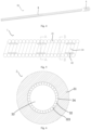
- Fig. 1 is a structural schematic of a rotation device according to a first embodiment (Embodiment 1) of the present invention.
- Fig. 2 is an axial cross-sectional view of a drive shaft in the rotation device according to the first embodiment of the present invention.
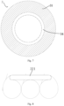
- Fig. 3 is a cross-sectional view of the drive shaft in the rotation device according to the first embodiment of the present invention.
- the rotation device 10 includes the drive shaft 1 and an instrument 2.
- the drive shaft 1 is coupled at a distal end thereof to the instrument 2 in order to drive rotation of the instrument 2.
- the drive shaft 1 is configured to transfer a torque and drive rotation of the instrument coupled thereto, which is for example an abrasive element.
- the rotation device 10 of this embodiment may be used to perform an intravascular surgical procedure, for example, for ablating tissue from the body through an intracorporeal conduit. For example, it may be used to ablate a calcified or fibrous arteriosclerotic plaque that occludes a blood vessel (e.g., coronary, peripheral or the like), thereby creating a smooth access lumen in the blood vessel.
- a blood vessel e.g., coronary, peripheral or the like
- the instrument 2 may be able to spin at a high speed, for example, in the range of 150000-190000 rpm, so that the rotation device 10 is used for high-speed rotary grinding at the vascular lesions, so as to realize the removal of the target tissue.
- the drive shaft 1 and the instrument 2 may be arranged coaxially or eccentrically.
- the instrument 2 may be entirely disposed on the drive shaft 1.
- the instrument 2 may define a central bore and may be disposed over the drive shaft 1 over an entire length of the central bore.
- the instrument 2 may be partially disposed on the drive shaft 1.
- it may be disposed over the drive shaft 1 over only part of the length of the central bore.
- the drive shaft 1 may extrude at the distal end out of the instrument 2. Therefore, the present invention is not limited to any particular approach for coupling the instrument 2 to the drive shaft 1.
- the drive shaft 1 includes an outer layer 11 and an inner layer 12.
- the outer layer 11 is a tubular structure defining an accommodating space and is preferably flexible.
- the inner layer 12 is accommodated in the space defined by the outer layer 11, and the inner layer 12 defines a central lumen 13 for receiving therein a guidewire (which is an external mechanism).
- the central lumen 13 allows the drive shaft 1 to be advanced, retracted and rotated relative to the guidewire.
- the outer layer 11 is a flexible tubular structure, it can bend and deform as desired when transferring a torque. That is, the outer layer 11 has not only pushing ability but also good compliance.
- the instrument 2 may be coupled to a distal end of the outer layer 11 so as to be able to be driven by the outer layer 11 to rotate.
- the instrument 2 and the drive shaft 1 may be separately formed and then assembled together.
- the instrument 2 and the drive shaft 1 may be integrally formed.
- the instrument 2 and the outer layer 11 may be integrally formed so that, for example, the outer layer 11 has a diametrically enlarged portion and the surface of at least one section of this portion is encrusted with an abrasive material.
- the abrasive section of the outer layer may form the instrument 2. When the outer layer is rotating at a high speed, the abrasive section is able to remove stenotic tissue from a blood vessel.
- the inner layer 12 is rollably arranged in the outer layer 11. More specifically, while the outer layer 11 is rotating at a high speed about the central lumen 13, the inner layer 12 rolls relative to both the outer layer 11 and the guidewire in the central lumen 13 so that only rolling friction may occur between the inner layer 12 and the guidewire. That is, with this design, rolling friction instead of sliding friction is allowed between the drive shaft 1 and the external mechanism. This enables reduced friction between the drive shaft and the guidewire during high-speed rotation of the drive shaft, thus avoiding possible failure of the guidewire, making the rotation device suitable for use with a commonly-used guidewire and resulting in improved surgical operability and lower surgical cost.
- the present invention is not limited to any particular approach for forming the outer layer 11.
- it may be braided from filaments, or formed by spiral cutting of a tube or by spiral coiling of wires.
- it may be implemented as a tubular elastic member such as a corrugated tube, or as an extruded polymer tube.
- the outer layer 11 is a spring coil formed of one or more wires, which is capable of providing a large torque and is desirably compliant.
- slits may be provided in the outer layer 11 to allow fluid(s) (e.g., saline and/or water or another fluid) to pass therethrough to an inner surface and/or an outer surface of the outer layer 11 to provide cooling and/or lubrication at interfaces of the outer layer 11, the inner layer 12 and the guidewire to further reduce wear and enhance heat dissipation.
- fluid(s) e.g., saline and/or water or another fluid
- slits may be provided between at least some turns of the spring coil in order to facilitate flowing of the fluids.
- individual turns of the spring coil may be spaced apart. That is, there may be slits between adjacent turns.
- some turns of the spring coil may be closely arranged to each other without any slit left therebetween.
- the outer layer 11 may be formed of a metallic material, or a combination of multiple metallic materials, or a combination of a metallic material and an organic polymeric material.
- the outer layer 11 may be formed of one of stainless steel, nickel, titanium and tungsten, or a combination thereof.
- the outer layer 11 is made of stainless steel or a nickel-titanium alloy, which enables the outer layer 11 have increased flexibility and superelasticity and thus ensures good compliance of the drive shaft 1.
- the present invention is not limited to any particular shape of the spirally coiled wires, and the shape may be elongate (e.g., rectangular), circular or elliptic.
- the inner layer 12 may include several rollers 121, which are disposed on the inner surface of the outer layer 11. More specifically, the several rollers 121 are disposed around an axis line of the outer layer 11 and define the central lumen 13.
- the present invention is not limited to any particular shape of the rollers 121. Examples of the rollers 121 may include ball rollers, spherical rollers, cylindrical rollers, needle rollers and tapered rollers.
- the inner layer 12 may include rollers either of different shapes or of the same shape. In this embodiment, the rollers 121 are ball rollers.
- the rollers 121 may be formed of either a metallic material or a non-metallic material.
- the metallic material may include, but are not limited to, carbon steel, bearing steel and stainless steel.
- the non-metallic material may include, but are not limited to, plastics and ceramics.
- the rollers 121 are made of a material with a relatively low friction coefficient, such as a polymer, which can additionally reduce friction.
- the polymer may be one of polytetrafluoroethylene (PTFE), polyimide, nylon and polyether ether ketone (PEEK), or a combination thereof.
- the rollers 121 are spirally arranged around the axis line of the outer layer 11.
- the rollers 121 may be arranged to form a continuous spiral extending around the axis line of the outer layer 11 from a proximal to distal end thereof.
- the rollers 121 may be arranged around the axis line of the outer layer 11 to form multiple spirals that are spaced apart from one another.
- the ball rollers are arranged around the axis line of the outer layer 11 to form a continuous spiral.
- the rollers 121 may be arranged around the axis line of the outer layer 11 to form at least one ring, which may be either circular or elliptic.
- the rollers 121 may be arranged around the axis line of the outer layer 11 to form multiple rings, which may be axially spaced apart or not.
- the present disclosure is not limited to any particular approach for attaching the outer layer 11 to the inner layer 12.
- the attachment of the two may be accomplished magnetically or by clamping or embedding.
- the rollers 121 may have magnetic properties and can be attracted to the outer layer 11.
- the outer layer 11 may have magnetic properties.
- a holder partially wrapping the rollers 12 may be provided either on the outer layer 11 or on the inner layer 12. The holder may be moveable with the rollers 121 and may be configured to separate the rollers apart, guide the rollers and hold the rollers within the outer layer.
- Fig. 9 shows an implementation of the holder 122 that is provided on the inner layer 12.
- the holder 122 on the inner layer 12 is a thin-walled cylinder provided with several holes or openings having a diameter greater than an outer diameter of the rollers 121, and the rollers 121 are disposed in the holes or openings so as to be able to 360° roll therein.
- a rollway may be provided on the inner surface of the outer layer 11, and a number of rollers 121 may be moveably disposed therein in such a manner that each of the rollers 121 partially protrudes out of the rollway and comes into contact with a guidewire.
- the rollway may have a shape depending on the arrangement of the roller.
- the rollway may be a continuous spiral, spaced multiple spirals, or at least one circular or elliptic rings.
- the rollers 121 are magnetically attached to the outer layer 11, as shown in Fig. 3 .
- One inch corresponds to 25.4 mm.
- An inner diameter of the drive shaft 1 is configured to be matched with the size of a commonly-used guidewire.
- the inner diameter of the drive shaft 1 may range from 0.008 inches to 0.04 inches so as to be suitable for use with commonly-used 0.014-inch guidewires.
- An outer diameter of the drive shaft 1 is configured to be matched with the size of a commonly-used delivery sheath.
- the outer diameter of the drive shaft 1 may range from 0.02 inches to 0.08 inches.
- a rotation device is substantially similar to that of Embodiment 1 as detailed below. Features also included in Embodiment 1 are not described in detail again.
- Fig. 4 is a structural schematic of the rotation device according to the second embodiment of the present disclosure.
- Fig. 5 is an axial sectional view of a drive shaft in the rotation device according to the second embodiment of the present disclosure.
- Fig. 6 is a cross-sectional view of the drive shaft of Fig. 5 taken along line A-A.
- Fig. 7 is a cross-sectional view of the drive shaft of Fig. 5 taken along line B-B.
- Fig. 8 is an enlarged partial view of the drive shaft of Fig. 5 .
- the rotation device 20 includes the drive shaft 3 and an instrument 4.
- the drive shaft 3 includes an outer layer 31 and an inner layer 32.
- the outer layer 31 is a tubular structure and is preferably flexible.
- the inner layer 32 is accommodated in a space defined by the outer layer 31 and defines a central lumen 33 for receiving therein a guidewire.
- each rollway 34 is projected as a circular ring on a plane perpendicular to the axial direction.
- the rollers 321 are cylindrical rollers, which are partially exposed out of the rollways 34 and come into contact with the guidewire.
- the rollers 321 may be formed of PTFE.
- the instrument is coupled to a distal end of the drive shaft and may be implemented as an abrasive element, for example, as shown in Fig. 1 or 4 .
- the instrument may be a cutter or a rotational atherectomy instrument such as an ablation burr.
- the instrument may include sensor(s) or the like capable of collecting data about an intracorporeal lumen and/or a site of interest therein (e.g., a lesion), such as its/their position(s), distance(s), temperature(s), contact force(s) or the like.
Landscapes
- Health & Medical Sciences (AREA)
- Engineering & Computer Science (AREA)
- General Engineering & Computer Science (AREA)
- Surgery (AREA)
- Life Sciences & Earth Sciences (AREA)
- Mechanical Engineering (AREA)
- General Health & Medical Sciences (AREA)
- Veterinary Medicine (AREA)
- Medical Informatics (AREA)
- Molecular Biology (AREA)
- Animal Behavior & Ethology (AREA)
- Biomedical Technology (AREA)
- Public Health (AREA)
- Heart & Thoracic Surgery (AREA)
- Nuclear Medicine, Radiotherapy & Molecular Imaging (AREA)
- Vascular Medicine (AREA)
- Oral & Maxillofacial Surgery (AREA)
- Ocean & Marine Engineering (AREA)
- Surgical Instruments (AREA)
- Flexible Shafts (AREA)
- Media Introduction/Drainage Providing Device (AREA)
Description
- The present invention relates to the field of medical devices, and more particularly to a rotation device and a drive shaft for use with a rotation device.
- With the continuous development of percutaneous coronary intervention (PCI), this therapy is indicated for increasingly complex lesions. Calcified coronary lesions, in particular severe and complex ones with tortuosity, calcified nodules and infiltration, have been challenging and risky for interventional treatment. Correct identification and assessment of calcified lesions and choice of suitable interventional treatment techniques are critical to more likely success, reduced complications and improved short and long term patient prognosis.
- Rotational atherectomy (RA) has become a procedure indispensable for successful PCI. A RA device ablates a calcified or fibrous arteriosclerotic plaque present in a blood vessel by high-speed spinning and cutting and thus creates an access passage with a smooth lumen, which facilitates the subsequent crossing of an implanted stent. A common RA device essentially consist of a flexible drive shaft and a burr which is disposed at a distal end of the flexible drive shaft and encrusted with an abrasive material such as diamond particles. The flexible drive shaft is used to drive high-speed spinning of the burr (in the range of approximately 150,000-190,000 rpm) and advance it so that the burr comes into contact with and ablate a lesional plaque. As a guidewire is typically inserted in an inner lumen of the flexible drive shaft, friction between the high-speed rotating flexible drive shaft and the guidewire tends to cause wear and tear of the guidewire, creating a risk of, for example, unwanted removal of a coating on the surface of the guidewire, thermal melting of the guidewire, or even uncoiling of a coiled section at a front end of the guidewire.
- Therefore, existing flexible drive shafts are unsuitable for use with guidewires commonly used in clinical practice (e.g., 0.356 mm (0.014-inch) wires) due to the risk of undesirable removal of a PTFE coating on the guidewire surface, uncoiling of a coiled section, or even worn breakage. For these reasons, in the current practice, special guidewires without a surface coating or a coiled section at the front end are usually used. However, since such special guidewires are poor in compliance and pushing ability, their use is not only conducive to surgical procedures, but also leads to higher surgical cost.
US2015272735A1 describes a catheter for minimally invasive implantation including inner and outer catheter tubes with a roller assembly provided at certain discrete locations along the length of the tubes in the radial gap separating the inner and outer tubes.US2009287234A1 describes a medical handpiece for cutting a treatment site with a rotating cutting tool received in a casing which also includes a series of circular cross-section bearings and a pair of inner and outer intervening members to support the shank of the cutting tool so that it can rotate smoothly during operation. - In order to overcome the above-described problems, it is an object of the present invention to provide a rotation device and a drive shaft for use with a rotation device. The drive shaft employs a modified structural design, which allows for reduced friction of the drive shaft with a guidewire and less loss due to such friction, thus avoiding failure of the guidewire due to melting, wear or uncoiling caused by excessive friction between the guidewire and the drive shaft. Thus, it is ensured that the drive shaft is suitable for use with guidewires commonly used in clinical practice, resulting in improved surgical operability and lower surgical cost.
- To this end, the present invention provides a drive shaft. The drive shaft includes an outer layer and an inner layer. The outer layer is a tubular structure defining an accommodating space, and the inner layer is arranged in the accommodating space and defines a central lumen for receiving therein a guidewire. The outer layer is rotatable about the central lumen, and the inner layer is rollable relative to both the outer layer and the guidewire and thus allows rolling friction to occur between the drive shaft and the external mechanism.
- The inner layer includes a number of rollers disposed on an inner surface of the outer layer.
The rollers are arranged around an axis line of the outer layer to form a spiral. - Optionally, the rollers may be arranged around the axis line of the outer layer to form one continuous spiral or multiple spirals that are spaced apart.
- Optionally, the rollers may be arranged around the axis line of the outer layer to form multiple rings, which are axially spaced apart, or abut one another.
- Optionally, the rollers may be ball rollers, spherical rollers, cylindrical rollers, needle rollers or tapered rollers.
- Optionally, a rollway may be arranged on an internal side of the outer layer, and the rollers may be moveably disposed in the rollway in such a manner that each of the rollers partially protrudes out of the rollway and comes into contact with the external mechanism.
- Optionally, the rollers may be made of a polymer.
- Optionally, slits may be provided in the outer layer to allow a fluid to flow therethrough to the inner surface and/or an outer surface of the drive shaft.
- Optionally, the outer layer may be connected to the inner layer magnetically, or by clamping or embedding.
- The above object is also attained by a rotation device provided in the present invention, which includes an instrument and the drive shaft as defined in any of the preceding paragraphs. The instrument is disposed at one end of the drive shaft and coupled to the outer layer of the drive shaft, and the instrument is configured to be driven by the outer layer to rotate.
- Optionally, the instrument and the drive shaft may be formed as separate parts or as an integral part. Alternatively, the instrument and the outer layer of the drive shaft may be formed as an integral part.
- Optionally, the instrument may be an abrasive element.
- The rotation device and the drive shaft of the present invention have at least one of the following advantages:
- First, through incorporating the rollable inner layer in the drive shaft, rolling friction instead of sliding friction can occur between the drive shaft and a guidewire. This results in effectively reduced friction between the drive shaft and the guidewire and less loss due to such friction, thus avoiding wear and tear of a surface coating, thermal melting and uncoiling of a coiled section, of the guidewire, during high-speed rotation of the drive shaft. Additionally, the risk of failure of the guidewire is reduced, and the drive shaft is made suitable for use with guidewires commonly used in clinical practice, resulting in improved surgical operability and lower surgical cost.
- Second, the inner layer may consist of commonly-used rollers such as ball rollers, spherical rollers, cylindrical rollers, needle rollers or tapered rollers. This design allows structural simplicity and low manufacturing cost.
- Third, the rollers in the inner layer may be made of a polymer with a low surface friction coefficient, which can additionally reduce friction and fictional loss.
- Fourth, slits may be provided in the outer layer to allow a fluid such as a coolant or lubricant to flow therethrough to the inner surface and/or the outer surface of the drive shaft, resulting in further reductions in friction and heat generated by friction.
- Those of ordinary skill in the art would appreciate that the following drawings are presented merely to enable a better understanding of the present invention rather than to limit the scope thereof in any sense. Therefore the scope of the invention is defined by the appended claims. In the drawings:
-
Fig. 1 is a structural schematic of a rotation device according to a first embodiment of the present invention; -
Fig. 2 is an axial sectional view of a drive shaft according to the first embodiment of the present invention; -
Fig. 3 is a cross-sectional of the drive shaft according to the first embodiment of the present invention; -
Fig. 4 is a structural schematic of a rotation device according to a second embodiment not according to the present invention; -
Fig. 5 is an axial sectional view of a drive shaft according to the second embodiment; -
Fig. 6 is a cross-sectional view of the drive shaft ofFig. 5 taken along line A-A; -
Fig. 7 is a cross-sectional view of the drive shaft ofFig. 5 taken along line B-B; -
Fig. 8 is an enlarged partial view of the drive shaft ofFig. 5 ; and -
Fig. 9 is a structural schematic of a holder according to an embodiment of the present disclosure. - In these figures,
- 10, 20-rotation device
- 1, 3-drive shaft;
- 11, 31-outer layer;
- 12, 32-inner layer;
- 13, 33-central lumen;
- 121, 321-roller;
- 34-rollway;
- 2, 4-instrument;
- 122-holder.
- Like reference numerals across the several views refer to like parts.
- Objectives, advantages and features of the present invention will become more apparent from the following more detailed description thereof made in conjunction with the accompanying drawings. Note that the figures are provided in a very simplified form not necessarily drawn to exact scale for the only purpose of helping to explain the disclosed embodiments in a more convenient and clearer way.
- As used herein, the singular forms "a", "an" and "the" include plural referents, unless the context clearly dictates otherwise. As used herein, the term "or" is generally employed in the sense of "and/or", unless the context clearly dictates otherwise.
- In the following description, the terms "distal", "proximal", "axial" and "circumferential" may be used for the sake of ease of description. When used to describe a rotation device, the term "distal" refers to an end thereof farther away from an operator who is operating the device, and the term "proximal" refers to an end closer to the operator. Moreover, the term "axial" refers to a direction along a longitudinal axis of the rotation device, and the term "circumferential" refers to a direction about the longitudinal axis of the rotation device. Further, when used to describe a drive shaft, the term "internal" refers to a side closer to a longitudinal axis of the drive shaft, and the term "external" refers to a side opposite to the "internal" side. As used herein, the term "multiple" is generally employed in the sense of "two or more" and "several" of "a non-specific number of', unless the context clearly dictates otherwise.
- The following description sets forth numerous specific details in order to provide a more thorough understanding of the present invention. However, it will be apparent to those skilled in the art that the present invention can be practiced without one or more of these specific details. In other instances, well-known technical features have not been described in order to avoid unnecessary obscuring of the present invention.
-
Fig. 1 is a structural schematic of a rotation device according to a first embodiment (Embodiment 1) of the present invention.Fig. 2 is an axial cross-sectional view of a drive shaft in the rotation device according to the first embodiment of the present invention.Fig. 3 is a cross-sectional view of the drive shaft in the rotation device according to the first embodiment of the present invention. - As shown in
Fig. 1 , therotation device 10 according to this embodiment includes thedrive shaft 1 and an instrument 2. Thedrive shaft 1 is coupled at a distal end thereof to the instrument 2 in order to drive rotation of the instrument 2. Typically, thedrive shaft 1 is configured to transfer a torque and drive rotation of the instrument coupled thereto, which is for example an abrasive element. Therotation device 10 of this embodiment may be used to perform an intravascular surgical procedure, for example, for ablating tissue from the body through an intracorporeal conduit. For example, it may be used to ablate a calcified or fibrous arteriosclerotic plaque that occludes a blood vessel (e.g., coronary, peripheral or the like), thereby creating a smooth access lumen in the blood vessel. To this end, the instrument 2 may be able to spin at a high speed, for example, in the range of 150000-190000 rpm, so that therotation device 10 is used for high-speed rotary grinding at the vascular lesions, so as to realize the removal of the target tissue. - The
drive shaft 1 and the instrument 2 may be arranged coaxially or eccentrically. The instrument 2 may be entirely disposed on thedrive shaft 1. For example, the instrument 2 may define a central bore and may be disposed over thedrive shaft 1 over an entire length of the central bore. Alternatively, the instrument 2 may be partially disposed on thedrive shaft 1. For example, it may be disposed over thedrive shaft 1 over only part of the length of the central bore. Further, thedrive shaft 1 may extrude at the distal end out of the instrument 2. Therefore, the present invention is not limited to any particular approach for coupling the instrument 2 to thedrive shaft 1. - As shown in
Fig. 2 , thedrive shaft 1 includes anouter layer 11 and aninner layer 12. Theouter layer 11 is a tubular structure defining an accommodating space and is preferably flexible. Theinner layer 12 is accommodated in the space defined by theouter layer 11, and theinner layer 12 defines acentral lumen 13 for receiving therein a guidewire (which is an external mechanism). Thecentral lumen 13 allows thedrive shaft 1 to be advanced, retracted and rotated relative to the guidewire. It should also be understood that when theouter layer 11 is a flexible tubular structure, it can bend and deform as desired when transferring a torque. That is, theouter layer 11 has not only pushing ability but also good compliance. Additionally, the instrument 2 may be coupled to a distal end of theouter layer 11 so as to be able to be driven by theouter layer 11 to rotate. In this embodiment, the instrument 2 and thedrive shaft 1 may be separately formed and then assembled together. In alternative embodiments, the instrument 2 and thedrive shaft 1 may be integrally formed. In particular, the instrument 2 and theouter layer 11 may be integrally formed so that, for example, theouter layer 11 has a diametrically enlarged portion and the surface of at least one section of this portion is encrusted with an abrasive material. In this case, the abrasive section of the outer layer may form the instrument 2. When the outer layer is rotating at a high speed, the abrasive section is able to remove stenotic tissue from a blood vessel. - Specifically, the
inner layer 12 is rollably arranged in theouter layer 11. More specifically, while theouter layer 11 is rotating at a high speed about thecentral lumen 13, theinner layer 12 rolls relative to both theouter layer 11 and the guidewire in thecentral lumen 13 so that only rolling friction may occur between theinner layer 12 and the guidewire. That is, with this design, rolling friction instead of sliding friction is allowed between thedrive shaft 1 and the external mechanism. This enables reduced friction between the drive shaft and the guidewire during high-speed rotation of the drive shaft, thus avoiding possible failure of the guidewire, making the rotation device suitable for use with a commonly-used guidewire and resulting in improved surgical operability and lower surgical cost. - Further, the present invention is not limited to any particular approach for forming the
outer layer 11. For example, it may be braided from filaments, or formed by spiral cutting of a tube or by spiral coiling of wires. Alternatively, it may be implemented as a tubular elastic member such as a corrugated tube, or as an extruded polymer tube. Preferably, theouter layer 11 is a spring coil formed of one or more wires, which is capable of providing a large torque and is desirably compliant. More preferably, slits may be provided in theouter layer 11 to allow fluid(s) (e.g., saline and/or water or another fluid) to pass therethrough to an inner surface and/or an outer surface of theouter layer 11 to provide cooling and/or lubrication at interfaces of theouter layer 11, theinner layer 12 and the guidewire to further reduce wear and enhance heat dissipation. For example, slits may be provided between at least some turns of the spring coil in order to facilitate flowing of the fluids. Specifically, individual turns of the spring coil may be spaced apart. That is, there may be slits between adjacent turns. Alternatively, some turns of the spring coil may be closely arranged to each other without any slit left therebetween. Theouter layer 11 may be formed of a metallic material, or a combination of multiple metallic materials, or a combination of a metallic material and an organic polymeric material. For example, theouter layer 11 may be formed of one of stainless steel, nickel, titanium and tungsten, or a combination thereof. Preferably, theouter layer 11 is made of stainless steel or a nickel-titanium alloy, which enables theouter layer 11 have increased flexibility and superelasticity and thus ensures good compliance of thedrive shaft 1. Further, the present invention is not limited to any particular shape of the spirally coiled wires, and the shape may be elongate (e.g., rectangular), circular or elliptic. - As shown in
Fig. 3 , theinner layer 12 may includeseveral rollers 121, which are disposed on the inner surface of theouter layer 11. More specifically, theseveral rollers 121 are disposed around an axis line of theouter layer 11 and define thecentral lumen 13. The present invention is not limited to any particular shape of therollers 121. Examples of therollers 121 may include ball rollers, spherical rollers, cylindrical rollers, needle rollers and tapered rollers. Theinner layer 12 may include rollers either of different shapes or of the same shape. In this embodiment, therollers 121 are ball rollers. Therollers 121 may be formed of either a metallic material or a non-metallic material. Examples of the metallic material may include, but are not limited to, carbon steel, bearing steel and stainless steel. Examples of the non-metallic material may include, but are not limited to, plastics and ceramics. Preferably, therollers 121 are made of a material with a relatively low friction coefficient, such as a polymer, which can additionally reduce friction. The polymer may be one of polytetrafluoroethylene (PTFE), polyimide, nylon and polyether ether ketone (PEEK), or a combination thereof. - According to the invention, the
rollers 121 are spirally arranged around the axis line of theouter layer 11. For example, therollers 121 may be arranged to form a continuous spiral extending around the axis line of theouter layer 11 from a proximal to distal end thereof. As another example, therollers 121 may be arranged around the axis line of theouter layer 11 to form multiple spirals that are spaced apart from one another. In this embodiment, as shown inFig. 2 , the ball rollers are arranged around the axis line of theouter layer 11 to form a continuous spiral. In an alternative embodiment, not according to the invention, therollers 121 may be arranged around the axis line of theouter layer 11 to form at least one ring, which may be either circular or elliptic. Optionally, therollers 121 may be arranged around the axis line of theouter layer 11 to form multiple rings, which may be axially spaced apart or not. - The present disclosure is not limited to any particular approach for attaching the
outer layer 11 to theinner layer 12. For example, the attachment of the two may be accomplished magnetically or by clamping or embedding. In the case of magnetic attachment, therollers 121 may have magnetic properties and can be attracted to theouter layer 11. Alternatively, theouter layer 11 may have magnetic properties. In the case of the attachment being accomplished by clamping, a holder partially wrapping therollers 12 may be provided either on theouter layer 11 or on theinner layer 12. The holder may be moveable with therollers 121 and may be configured to separate the rollers apart, guide the rollers and hold the rollers within the outer layer. -
Fig. 9 shows an implementation of theholder 122 that is provided on theinner layer 12. As shown inFig. 9 , theholder 122 on theinner layer 12 is a thin-walled cylinder provided with several holes or openings having a diameter greater than an outer diameter of therollers 121, and therollers 121 are disposed in the holes or openings so as to be able to 360° roll therein. In the case of the attachment being accomplished by embedding, a rollway may be provided on the inner surface of theouter layer 11, and a number ofrollers 121 may be moveably disposed therein in such a manner that each of therollers 121 partially protrudes out of the rollway and comes into contact with a guidewire. The rollway may have a shape depending on the arrangement of the roller. For example, the rollway may be a continuous spiral, spaced multiple spirals, or at least one circular or elliptic rings. In this embodiment, therollers 121 are magnetically attached to theouter layer 11, as shown inFig. 3 . - One inch corresponds to 25.4 mm.
- An inner diameter of the
drive shaft 1 is configured to be matched with the size of a commonly-used guidewire. Optionally, the inner diameter of thedrive shaft 1 may range from 0.008 inches to 0.04 inches so as to be suitable for use with commonly-used 0.014-inch guidewires. An outer diameter of thedrive shaft 1 is configured to be matched with the size of a commonly-used delivery sheath. Optionally, the outer diameter of thedrive shaft 1 may range from 0.02 inches to 0.08 inches. - A rotation device according to a second embodiment is substantially similar to that of
Embodiment 1 as detailed below. Features also included inEmbodiment 1 are not described in detail again. -
Fig. 4 is a structural schematic of the rotation device according to the second embodiment of the present disclosure.Fig. 5 is an axial sectional view of a drive shaft in the rotation device according to the second embodiment of the present disclosure. -
Fig. 6 is a cross-sectional view of the drive shaft ofFig. 5 taken along line A-A.Fig. 7 is a cross-sectional view of the drive shaft ofFig. 5 taken along line B-B.Fig. 8 is an enlarged partial view of the drive shaft ofFig. 5 . - As shown in
Figs. 4 and 5 , therotation device 20 according to the second embodiment includes thedrive shaft 3 and an instrument 4. Thedrive shaft 3 includes anouter layer 31 and aninner layer 32. Theouter layer 31 is a tubular structure and is preferably flexible. Theinner layer 32 is accommodated in a space defined by theouter layer 31 and defines acentral lumen 33 for receiving therein a guidewire. - As shown in
Figs. 5 to 8 , the internal side of theouter layer 31 is provided with rollway(s) 34. Further,multiple rollways 34, which are axially spaced apart from one another, are arranged on an internal side of theouter layer 31, andmultiple rollers 321 are evenly arranged in each of therollways 34 around thecentral lumen 33. As shown inFig. 7 , eachrollway 34 is projected as a circular ring on a plane perpendicular to the axial direction. - In this embodiment, the
rollers 321 are cylindrical rollers, which are partially exposed out of therollways 34 and come into contact with the guidewire. In particular, therollers 321 may be formed of PTFE. - As with the above embodiment, the instrument is coupled to a distal end of the drive shaft and may be implemented as an abrasive element, for example, as shown in
Fig. 1 or4 . In exemplary embodiments, the instrument may be a cutter or a rotational atherectomy instrument such as an ablation burr. The instrument may include sensor(s) or the like capable of collecting data about an intracorporeal lumen and/or a site of interest therein (e.g., a lesion), such as its/their position(s), distance(s), temperature(s), contact force(s) or the like. - While a few preferred embodiments of the present invention have been described above, the scope of the invention is in no way limited to these disclosed embodiments. Changes may be made to the structures provided in the above embodiments within the scope of the present invention defined in the claims. For example, polymer coatings, preferably, PTFE coatings with a low friction coefficient, may be applied to the outer and inner layers in order to further reduce friction. Those skilled in the art can devise other embodiments on the basis of the description of the foregoing embodiments.
- In summary, according to embodiments of the present invention, through incorporating the rollable inner layer in the drive shaft, rolling friction instead of sliding friction can occur between the drive shaft and a guidewire. This results in effectively reduced friction between the drive shaft and the guidewire and less loss due to such friction, thus avoiding wear and tear of a surface coating, thermal melting and uncoiling of a coiled section, of the guidewire, during high-speed rotation of the drive shaft. Additionally, the risk of failure of the guidewire is reduced, and the drive shaft is made suitable for use with guidewires commonly used in clinical practice, resulting in improved surgical operability and lower surgical cost.
- The description presented above is merely that of a few preferred embodiments of the present invention and is not intended to limit the scope thereof in any sense. Therefore the scope of the invention is defined by the appended claims.
Claims (11)
- A medical drive shaft (1, 3), the drive shaft (1, 3) comprising an outer layer (11, 31) and an inner layer (12, 32), the outer layer (11, 31) being a tubular structure defining an accommodating space, the inner layer (12, 32) arranged in the accommodating space and defining a central lumen (13, 33) for receiving therein a guidewire, wherein the outer layer (11, 31) is rotatable about the central lumen (13, 33), and the inner layer (12, 32) is rollable relative to both the outer layer (11, 31) and the guidewire and thus rolling friction is created between the drive shaft (1, 3) and the guidewire through the inner layer (12, 32), wherein the inner layer (12, 32) includes a number of rollers (121, 321) disposed on an inner surface of the outer layer (11, 31), the rollers (121, 321) are arranged around an axis line of the outer layer (11, 31) to form a spiral.
- The drive shaft (1, 3) of claim 1, wherein the rollers (121, 321) are arranged around the axis line of the outer layer (11, 31) to form one continuous spiral, or wherein the rollers (121, 321) are arranged around the axis line of the outer layer (11, 31) to form a plurality of spaced spirals.
- The drive shaft (1, 3) of claim 1, wherein the rollers (121, 321) are arranged around the axis line of the outer layer (11, 31) to form a plurality of rings, which are axially spaced apart, or abut one another.
- The drive shaft (1, 3) of any one of claims 1 to 3, wherein the rollers (121, 321) are ball rollers, spherical rollers, cylindrical rollers, needle rollers or tapered rollers.
- The drive shaft (1, 3) of any one of claims 1 to 3, wherein a rollway (34) is arranged on an internal side of the outer layer (11, 31), and the rollers (121, 321) are moveably disposed in the rollway (34) in such a manner that each of the rollers (121, 321) partially protrudes out of the rollway (34) and comes into contact with the guidewire.
- The drive shaft (1, 3) of any one of claims 1 to 3, wherein the rollers (121, 321) are made of a polymer.
- The drive shaft (1, 3) of claim 1, wherein slits are provided in the outer layer (11, 31) to allow a fluid to flow therethrough to the inner surface and/or an outer surface of the drive shaft (1, 3).
- The drive shaft (1, 3) of claim 1, wherein the outer layer (11, 31) is connected to the inner layer (12, 32) magnetically, or by clamping or embedding.
- A rotation device (10, 20) comprising an instrument (2, 4) and the drive shaft (1, 3) of any one of claims 1 to 8, the instrument (2, 4) disposed at one end of the drive shaft (1, 3) and coupled to the outer layer (11, 31) of the drive shaft (1, 3), the instrument (2, 4) being configured to be driven by the outer layer (11, 31) to rotate.
- The rotation device (10, 20) of claim 9, wherein the instrument (2, 4) and the drive shaft (1, 3) are formed as separate parts, or wherein the instrument (2, 4) and the outer layer (11, 31) of the drive shaft (1, 3) are formed as an integral part.
- The rotation device (10, 20) of claim 9 or 10, wherein the instrument (2, 4) is an abrasive element.
Applications Claiming Priority (2)
| Application Number | Priority Date | Filing Date | Title |
|---|---|---|---|
| CN201910925120.5A CN110985521B (en) | 2019-09-27 | 2019-09-27 | Rotating device and drive shaft for the rotating device |
| PCT/CN2020/115872 WO2021057588A1 (en) | 2019-09-27 | 2020-09-17 | Rotation device, and drive shaft for rotation device |
Publications (4)
| Publication Number | Publication Date |
|---|---|
| EP4018945A1 EP4018945A1 (en) | 2022-06-29 |
| EP4018945A4 EP4018945A4 (en) | 2022-10-19 |
| EP4018945B1 true EP4018945B1 (en) | 2024-09-04 |
| EP4018945C0 EP4018945C0 (en) | 2024-09-04 |
Family
ID=70081825
Family Applications (1)
| Application Number | Title | Priority Date | Filing Date |
|---|---|---|---|
| EP20867549.6A Active EP4018945B1 (en) | 2019-09-27 | 2020-09-17 | Rotation device, and drive shaft for rotation device |
Country Status (4)
| Country | Link |
|---|---|
| US (1) | US12502197B2 (en) |
| EP (1) | EP4018945B1 (en) |
| CN (1) | CN110985521B (en) |
| WO (1) | WO2021057588A1 (en) |
Families Citing this family (3)
| Publication number | Priority date | Publication date | Assignee | Title |
|---|---|---|---|---|
| CN110985521B (en) * | 2019-09-27 | 2025-04-04 | 上海微创旋律医疗科技有限公司 | Rotating device and drive shaft for the rotating device |
| CN112237463A (en) * | 2020-09-21 | 2021-01-19 | 上海微创医疗器械(集团)有限公司 | Rotary grinding catheter |
| CN116269917A (en) * | 2023-03-06 | 2023-06-23 | 江苏百纳医疗科技有限公司 | A new patch suturing device |
Family Cites Families (18)
| Publication number | Priority date | Publication date | Assignee | Title |
|---|---|---|---|---|
| US6217595B1 (en) * | 1996-11-18 | 2001-04-17 | Shturman Cardiology Systems, Inc. | Rotational atherectomy device |
| US6818001B2 (en) * | 2000-04-05 | 2004-11-16 | Pathway Medical Technologies, Inc. | Intralumenal material removal systems and methods |
| US6749341B2 (en) * | 2002-05-22 | 2004-06-15 | The Anspach Effort, Inc. | Ball bearing |
| JP4105200B2 (en) * | 2006-05-11 | 2008-06-25 | 株式会社ナカニシ | Medical handpiece |
| US7674253B2 (en) * | 2006-08-18 | 2010-03-09 | Kensey Nash Corporation | Catheter for conducting a procedure within a lumen, duct or organ of a living being |
| AU2009234392A1 (en) * | 2008-04-10 | 2009-10-15 | Atheromed, Inc. | Atherectomy devices and methods |
| US8295902B2 (en) * | 2008-11-11 | 2012-10-23 | Shifamed Holdings, Llc | Low profile electrode assembly |
| US9155555B2 (en) * | 2012-01-31 | 2015-10-13 | Medtronic Xomed, Inc. | Surgical instrument with distal bearing assembly |
| EP2868289A1 (en) * | 2013-11-01 | 2015-05-06 | ECP Entwicklungsgesellschaft mbH | Flexible catheter with a drive shaft |
| EP2923665B1 (en) * | 2014-03-26 | 2018-10-17 | Biotronik AG | Catheter device for the minimally invasive implantation of a vascular implant, in particular for interventional catheter-assisted aortic valve implantation |
| EP3226784B1 (en) | 2014-12-04 | 2020-09-09 | Boston Scientific Scimed, Inc. | Rotatable medical device |
| CN107178557A (en) * | 2016-03-09 | 2017-09-19 | 西南石油大学 | It is a kind of to realize the screw-casing floating-ring bearing of stable rotation |
| US10905457B2 (en) | 2016-06-06 | 2021-02-02 | Terumo Kabushiki Kaisha | Device handle for a medical device |
| WO2018052121A1 (en) * | 2016-09-16 | 2018-03-22 | テルモ株式会社 | Medical device |
| US11523833B2 (en) * | 2017-02-17 | 2022-12-13 | Globus Medical, Inc. | Surgical rotary tool |
| JP2021004609A (en) * | 2017-09-05 | 2021-01-14 | テルモ株式会社 | Bearing and medical device |
| CN110985521B (en) * | 2019-09-27 | 2025-04-04 | 上海微创旋律医疗科技有限公司 | Rotating device and drive shaft for the rotating device |
| CN211009538U (en) * | 2019-09-27 | 2020-07-14 | 上海微创医疗器械(集团)有限公司 | Rotary device and drive shaft for a rotary device |
-
2019
- 2019-09-27 CN CN201910925120.5A patent/CN110985521B/en active Active
-
2020
- 2020-09-17 EP EP20867549.6A patent/EP4018945B1/en active Active
- 2020-09-17 WO PCT/CN2020/115872 patent/WO2021057588A1/en not_active Ceased
- 2020-09-17 US US17/641,239 patent/US12502197B2/en active Active
Also Published As
| Publication number | Publication date |
|---|---|
| EP4018945A4 (en) | 2022-10-19 |
| CN110985521A (en) | 2020-04-10 |
| WO2021057588A1 (en) | 2021-04-01 |
| EP4018945A1 (en) | 2022-06-29 |
| US20220330971A1 (en) | 2022-10-20 |
| CN110985521B (en) | 2025-04-04 |
| US12502197B2 (en) | 2025-12-23 |
| EP4018945C0 (en) | 2024-09-04 |
Similar Documents
| Publication | Publication Date | Title |
|---|---|---|
| US11896260B2 (en) | Tissue-removing catheter | |
| CN111093730B (en) | Driving shaft cover with heat conducting component | |
| US12502197B2 (en) | Rotation device, and drive shaft for rotation device | |
| US10470794B2 (en) | Atherectomy devices and methods | |
| US11931062B2 (en) | Atherectomy devices and methods | |
| CN112237463A (en) | Rotary grinding catheter | |
| WO2018221460A1 (en) | Medical device and method | |
| WO2018052121A1 (en) | Medical device | |
| US20200191196A1 (en) | Bearing and medical device | |
| US12053204B2 (en) | Medical device and method | |
| CN211009538U (en) | Rotary device and drive shaft for a rotary device | |
| CN213030778U (en) | Rotary grinding catheter | |
| EP4140421B1 (en) | Tissue-removing catheter with distal tip | |
| US12521141B2 (en) | Tissue-removing catheter including drive assembly | |
| EP4312830B1 (en) | Tissue-removing catheter with coupled inner liner | |
| US20220370095A1 (en) | Tissue-removing catheter with guidewire isolation liner | |
| CN119867885A (en) | Rotary grinding structure and rotary grinding catheter system |
Legal Events
| Date | Code | Title | Description |
|---|---|---|---|
| STAA | Information on the status of an ep patent application or granted ep patent |
Free format text: STATUS: THE INTERNATIONAL PUBLICATION HAS BEEN MADE |
|
| PUAI | Public reference made under article 153(3) epc to a published international application that has entered the european phase |
Free format text: ORIGINAL CODE: 0009012 |
|
| STAA | Information on the status of an ep patent application or granted ep patent |
Free format text: STATUS: REQUEST FOR EXAMINATION WAS MADE |
|
| 17P | Request for examination filed |
Effective date: 20220322 |
|
| AK | Designated contracting states |
Kind code of ref document: A1 Designated state(s): AL AT BE BG CH CY CZ DE DK EE ES FI FR GB GR HR HU IE IS IT LI LT LU LV MC MK MT NL NO PL PT RO RS SE SI SK SM TR |
|
| A4 | Supplementary search report drawn up and despatched |
Effective date: 20220919 |
|
| RIC1 | Information provided on ipc code assigned before grant |
Ipc: A61B 17/00 20060101ALN20220913BHEP Ipc: A61B 17/32 20060101ALI20220913BHEP Ipc: A61B 17/3207 20060101AFI20220913BHEP |
|
| DAV | Request for validation of the european patent (deleted) | ||
| DAX | Request for extension of the european patent (deleted) | ||
| GRAP | Despatch of communication of intention to grant a patent |
Free format text: ORIGINAL CODE: EPIDOSNIGR1 |
|
| STAA | Information on the status of an ep patent application or granted ep patent |
Free format text: STATUS: GRANT OF PATENT IS INTENDED |
|
| RIC1 | Information provided on ipc code assigned before grant |
Ipc: F16C 1/28 20060101ALN20240419BHEP Ipc: F16C 1/26 20060101ALN20240419BHEP Ipc: F16C 1/06 20060101ALN20240419BHEP Ipc: A61B 17/00 20060101ALN20240419BHEP Ipc: A61B 17/32 20060101ALI20240419BHEP Ipc: A61B 17/3207 20060101AFI20240419BHEP |
|
| INTG | Intention to grant announced |
Effective date: 20240514 |
|
| GRAS | Grant fee paid |
Free format text: ORIGINAL CODE: EPIDOSNIGR3 |
|
| GRAA | (expected) grant |
Free format text: ORIGINAL CODE: 0009210 |
|
| STAA | Information on the status of an ep patent application or granted ep patent |
Free format text: STATUS: THE PATENT HAS BEEN GRANTED |
|
| AK | Designated contracting states |
Kind code of ref document: B1 Designated state(s): AL AT BE BG CH CY CZ DE DK EE ES FI FR GB GR HR HU IE IS IT LI LT LU LV MC MK MT NL NO PL PT RO RS SE SI SK SM TR |
|
| REG | Reference to a national code |
Ref country code: GB Ref legal event code: FG4D |
|
| REG | Reference to a national code |
Ref country code: CH Ref legal event code: EP |
|
| REG | Reference to a national code |
Ref country code: IE Ref legal event code: FG4D |
|
| REG | Reference to a national code |
Ref country code: DE Ref legal event code: R096 Ref document number: 602020037300 Country of ref document: DE |
|
| U01 | Request for unitary effect filed |
Effective date: 20240930 |
|
| U07 | Unitary effect registered |
Designated state(s): AT BE BG DE DK EE FI FR IT LT LU LV MT NL PT RO SE SI Effective date: 20241024 |
|
| U20 | Renewal fee for the european patent with unitary effect paid |
Year of fee payment: 5 Effective date: 20241126 |
|
| PG25 | Lapsed in a contracting state [announced via postgrant information from national office to epo] |
Ref country code: NO Free format text: LAPSE BECAUSE OF FAILURE TO SUBMIT A TRANSLATION OF THE DESCRIPTION OR TO PAY THE FEE WITHIN THE PRESCRIBED TIME-LIMIT Effective date: 20241204 |
|
| PG25 | Lapsed in a contracting state [announced via postgrant information from national office to epo] |
Ref country code: PL Free format text: LAPSE BECAUSE OF FAILURE TO SUBMIT A TRANSLATION OF THE DESCRIPTION OR TO PAY THE FEE WITHIN THE PRESCRIBED TIME-LIMIT Effective date: 20240904 Ref country code: GR Free format text: LAPSE BECAUSE OF FAILURE TO SUBMIT A TRANSLATION OF THE DESCRIPTION OR TO PAY THE FEE WITHIN THE PRESCRIBED TIME-LIMIT Effective date: 20241205 |
|
| PG25 | Lapsed in a contracting state [announced via postgrant information from national office to epo] |
Ref country code: HR Free format text: LAPSE BECAUSE OF FAILURE TO SUBMIT A TRANSLATION OF THE DESCRIPTION OR TO PAY THE FEE WITHIN THE PRESCRIBED TIME-LIMIT Effective date: 20240904 |
|
| PG25 | Lapsed in a contracting state [announced via postgrant information from national office to epo] |
Ref country code: ES Free format text: LAPSE BECAUSE OF FAILURE TO SUBMIT A TRANSLATION OF THE DESCRIPTION OR TO PAY THE FEE WITHIN THE PRESCRIBED TIME-LIMIT Effective date: 20240904 Ref country code: RS Free format text: LAPSE BECAUSE OF FAILURE TO SUBMIT A TRANSLATION OF THE DESCRIPTION OR TO PAY THE FEE WITHIN THE PRESCRIBED TIME-LIMIT Effective date: 20241204 |
|
| PG25 | Lapsed in a contracting state [announced via postgrant information from national office to epo] |
Ref country code: RS Free format text: LAPSE BECAUSE OF FAILURE TO SUBMIT A TRANSLATION OF THE DESCRIPTION OR TO PAY THE FEE WITHIN THE PRESCRIBED TIME-LIMIT Effective date: 20241204 Ref country code: PL Free format text: LAPSE BECAUSE OF FAILURE TO SUBMIT A TRANSLATION OF THE DESCRIPTION OR TO PAY THE FEE WITHIN THE PRESCRIBED TIME-LIMIT Effective date: 20240904 Ref country code: NO Free format text: LAPSE BECAUSE OF FAILURE TO SUBMIT A TRANSLATION OF THE DESCRIPTION OR TO PAY THE FEE WITHIN THE PRESCRIBED TIME-LIMIT Effective date: 20241204 Ref country code: HR Free format text: LAPSE BECAUSE OF FAILURE TO SUBMIT A TRANSLATION OF THE DESCRIPTION OR TO PAY THE FEE WITHIN THE PRESCRIBED TIME-LIMIT Effective date: 20240904 Ref country code: GR Free format text: LAPSE BECAUSE OF FAILURE TO SUBMIT A TRANSLATION OF THE DESCRIPTION OR TO PAY THE FEE WITHIN THE PRESCRIBED TIME-LIMIT Effective date: 20241205 Ref country code: ES Free format text: LAPSE BECAUSE OF FAILURE TO SUBMIT A TRANSLATION OF THE DESCRIPTION OR TO PAY THE FEE WITHIN THE PRESCRIBED TIME-LIMIT Effective date: 20240904 |
|
| PG25 | Lapsed in a contracting state [announced via postgrant information from national office to epo] |
Ref country code: IS Free format text: LAPSE BECAUSE OF FAILURE TO SUBMIT A TRANSLATION OF THE DESCRIPTION OR TO PAY THE FEE WITHIN THE PRESCRIBED TIME-LIMIT Effective date: 20250104 |
|
| PG25 | Lapsed in a contracting state [announced via postgrant information from national office to epo] |
Ref country code: SM Free format text: LAPSE BECAUSE OF FAILURE TO SUBMIT A TRANSLATION OF THE DESCRIPTION OR TO PAY THE FEE WITHIN THE PRESCRIBED TIME-LIMIT Effective date: 20240904 |
|
| PG25 | Lapsed in a contracting state [announced via postgrant information from national office to epo] |
Ref country code: CZ Free format text: LAPSE BECAUSE OF FAILURE TO SUBMIT A TRANSLATION OF THE DESCRIPTION OR TO PAY THE FEE WITHIN THE PRESCRIBED TIME-LIMIT Effective date: 20240904 |
|
| PG25 | Lapsed in a contracting state [announced via postgrant information from national office to epo] |
Ref country code: SK Free format text: LAPSE BECAUSE OF FAILURE TO SUBMIT A TRANSLATION OF THE DESCRIPTION OR TO PAY THE FEE WITHIN THE PRESCRIBED TIME-LIMIT Effective date: 20240904 |
|
| REG | Reference to a national code |
Ref country code: CH Ref legal event code: PL |
|
| PG25 | Lapsed in a contracting state [announced via postgrant information from national office to epo] |
Ref country code: MC Free format text: LAPSE BECAUSE OF FAILURE TO SUBMIT A TRANSLATION OF THE DESCRIPTION OR TO PAY THE FEE WITHIN THE PRESCRIBED TIME-LIMIT Effective date: 20240904 |
|
| PLBE | No opposition filed within time limit |
Free format text: ORIGINAL CODE: 0009261 |
|
| STAA | Information on the status of an ep patent application or granted ep patent |
Free format text: STATUS: NO OPPOSITION FILED WITHIN TIME LIMIT |
|
| PG25 | Lapsed in a contracting state [announced via postgrant information from national office to epo] |
Ref country code: CH Free format text: LAPSE BECAUSE OF NON-PAYMENT OF DUE FEES Effective date: 20240930 |
|
| PG25 | Lapsed in a contracting state [announced via postgrant information from national office to epo] |
Ref country code: IE Free format text: LAPSE BECAUSE OF NON-PAYMENT OF DUE FEES Effective date: 20240917 |
|
| 26N | No opposition filed |
Effective date: 20250605 |
|
| PGFP | Annual fee paid to national office [announced via postgrant information from national office to epo] |
Ref country code: GB Payment date: 20250919 Year of fee payment: 6 |
|
| U20 | Renewal fee for the european patent with unitary effect paid |
Year of fee payment: 6 Effective date: 20250924 |
|
| PG25 | Lapsed in a contracting state [announced via postgrant information from national office to epo] |
Ref country code: CY Free format text: LAPSE BECAUSE OF FAILURE TO SUBMIT A TRANSLATION OF THE DESCRIPTION OR TO PAY THE FEE WITHIN THE PRESCRIBED TIME-LIMIT; INVALID AB INITIO Effective date: 20200917 |
|
| PG25 | Lapsed in a contracting state [announced via postgrant information from national office to epo] |
Ref country code: HU Free format text: LAPSE BECAUSE OF FAILURE TO SUBMIT A TRANSLATION OF THE DESCRIPTION OR TO PAY THE FEE WITHIN THE PRESCRIBED TIME-LIMIT; INVALID AB INITIO Effective date: 20200917 |