EP4018139B1 - Refrigerator - Google Patents
Refrigerator Download PDFInfo
- Publication number
- EP4018139B1 EP4018139B1 EP21750204.6A EP21750204A EP4018139B1 EP 4018139 B1 EP4018139 B1 EP 4018139B1 EP 21750204 A EP21750204 A EP 21750204A EP 4018139 B1 EP4018139 B1 EP 4018139B1
- Authority
- EP
- European Patent Office
- Prior art keywords
- moving part
- horizontal
- cabinet
- vertical
- pair
- Prior art date
- Legal status (The legal status is an assumption and is not a legal conclusion. Google has not performed a legal analysis and makes no representation as to the accuracy of the status listed.)
- Active
Links
Images








Classifications
-
- F—MECHANICAL ENGINEERING; LIGHTING; HEATING; WEAPONS; BLASTING
- F25—REFRIGERATION OR COOLING; COMBINED HEATING AND REFRIGERATION SYSTEMS; HEAT PUMP SYSTEMS; MANUFACTURE OR STORAGE OF ICE; LIQUEFACTION SOLIDIFICATION OF GASES
- F25D—REFRIGERATORS; COLD ROOMS; ICE-BOXES; COOLING OR FREEZING APPARATUS NOT OTHERWISE PROVIDED FOR
- F25D23/00—General constructional features
- F25D23/02—Doors; Covers
- F25D23/028—Details
-
- E—FIXED CONSTRUCTIONS
- E05—LOCKS; KEYS; WINDOW OR DOOR FITTINGS; SAFES
- E05D—HINGES OR SUSPENSION DEVICES FOR DOORS, WINDOWS OR WINGS
- E05D7/00—Hinges or pivots of special construction
- E05D7/04—Hinges adjustable relative to the wing or the frame
-
- E—FIXED CONSTRUCTIONS
- E05—LOCKS; KEYS; WINDOW OR DOOR FITTINGS; SAFES
- E05D—HINGES OR SUSPENSION DEVICES FOR DOORS, WINDOWS OR WINGS
- E05D7/00—Hinges or pivots of special construction
- E05D7/04—Hinges adjustable relative to the wing or the frame
- E05D7/0415—Hinges adjustable relative to the wing or the frame with adjusting drive means
- E05D7/0423—Screw-and-nut mechanisms
-
- E—FIXED CONSTRUCTIONS
- E05—LOCKS; KEYS; WINDOW OR DOOR FITTINGS; SAFES
- E05D—HINGES OR SUSPENSION DEVICES FOR DOORS, WINDOWS OR WINGS
- E05D7/00—Hinges or pivots of special construction
- E05D7/08—Hinges or pivots of special construction for use in suspensions comprising two spigots placed at opposite edges of the wing, especially at the top and the bottom, e.g. trunnions
- E05D7/081—Hinges or pivots of special construction for use in suspensions comprising two spigots placed at opposite edges of the wing, especially at the top and the bottom, e.g. trunnions the pivot axis of the wing being situated near one edge of the wing, especially at the top and bottom, e.g. trunnions
-
- E—FIXED CONSTRUCTIONS
- E05—LOCKS; KEYS; WINDOW OR DOOR FITTINGS; SAFES
- E05D—HINGES OR SUSPENSION DEVICES FOR DOORS, WINDOWS OR WINGS
- E05D7/00—Hinges or pivots of special construction
- E05D7/04—Hinges adjustable relative to the wing or the frame
- E05D2007/0469—Hinges adjustable relative to the wing or the frame in an axial direction
-
- E—FIXED CONSTRUCTIONS
- E05—LOCKS; KEYS; WINDOW OR DOOR FITTINGS; SAFES
- E05D—HINGES OR SUSPENSION DEVICES FOR DOORS, WINDOWS OR WINGS
- E05D7/00—Hinges or pivots of special construction
- E05D7/04—Hinges adjustable relative to the wing or the frame
- E05D2007/0484—Hinges adjustable relative to the wing or the frame in a radial direction
-
- E—FIXED CONSTRUCTIONS
- E05—LOCKS; KEYS; WINDOW OR DOOR FITTINGS; SAFES
- E05Y—INDEXING SCHEME ASSOCIATED WITH SUBCLASSES E05D AND E05F, RELATING TO CONSTRUCTION ELEMENTS, ELECTRIC CONTROL, POWER SUPPLY, POWER SIGNAL OR TRANSMISSION, USER INTERFACES, MOUNTING OR COUPLING, DETAILS, ACCESSORIES, AUXILIARY OPERATIONS NOT OTHERWISE PROVIDED FOR, APPLICATION THEREOF
- E05Y2201/00—Constructional elements; Accessories therefor
- E05Y2201/60—Suspension or transmission members; Accessories therefor
- E05Y2201/622—Suspension or transmission members elements
- E05Y2201/676—Transmission of human force
- E05Y2201/68—Handles, cranks
-
- E—FIXED CONSTRUCTIONS
- E05—LOCKS; KEYS; WINDOW OR DOOR FITTINGS; SAFES
- E05Y—INDEXING SCHEME ASSOCIATED WITH SUBCLASSES E05D AND E05F, RELATING TO CONSTRUCTION ELEMENTS, ELECTRIC CONTROL, POWER SUPPLY, POWER SIGNAL OR TRANSMISSION, USER INTERFACES, MOUNTING OR COUPLING, DETAILS, ACCESSORIES, AUXILIARY OPERATIONS NOT OTHERWISE PROVIDED FOR, APPLICATION THEREOF
- E05Y2600/00—Mounting or coupling arrangements for elements provided for in this subclass
- E05Y2600/10—Adjustable
- E05Y2600/12—Adjustable by manual operation
-
- E—FIXED CONSTRUCTIONS
- E05—LOCKS; KEYS; WINDOW OR DOOR FITTINGS; SAFES
- E05Y—INDEXING SCHEME ASSOCIATED WITH SUBCLASSES E05D AND E05F, RELATING TO CONSTRUCTION ELEMENTS, ELECTRIC CONTROL, POWER SUPPLY, POWER SIGNAL OR TRANSMISSION, USER INTERFACES, MOUNTING OR COUPLING, DETAILS, ACCESSORIES, AUXILIARY OPERATIONS NOT OTHERWISE PROVIDED FOR, APPLICATION THEREOF
- E05Y2600/00—Mounting or coupling arrangements for elements provided for in this subclass
- E05Y2600/10—Adjustable
- E05Y2600/14—Adjustable with position retaining means
-
- E—FIXED CONSTRUCTIONS
- E05—LOCKS; KEYS; WINDOW OR DOOR FITTINGS; SAFES
- E05Y—INDEXING SCHEME ASSOCIATED WITH SUBCLASSES E05D AND E05F, RELATING TO CONSTRUCTION ELEMENTS, ELECTRIC CONTROL, POWER SUPPLY, POWER SIGNAL OR TRANSMISSION, USER INTERFACES, MOUNTING OR COUPLING, DETAILS, ACCESSORIES, AUXILIARY OPERATIONS NOT OTHERWISE PROVIDED FOR, APPLICATION THEREOF
- E05Y2600/00—Mounting or coupling arrangements for elements provided for in this subclass
- E05Y2600/50—Mounting methods; Positioning
- E05Y2600/51—Screwing or bolting
-
- E—FIXED CONSTRUCTIONS
- E05—LOCKS; KEYS; WINDOW OR DOOR FITTINGS; SAFES
- E05Y—INDEXING SCHEME ASSOCIATED WITH SUBCLASSES E05D AND E05F, RELATING TO CONSTRUCTION ELEMENTS, ELECTRIC CONTROL, POWER SUPPLY, POWER SIGNAL OR TRANSMISSION, USER INTERFACES, MOUNTING OR COUPLING, DETAILS, ACCESSORIES, AUXILIARY OPERATIONS NOT OTHERWISE PROVIDED FOR, APPLICATION THEREOF
- E05Y2600/00—Mounting or coupling arrangements for elements provided for in this subclass
- E05Y2600/60—Mounting or coupling members; Accessories therefor
- E05Y2600/61—Threaded members
-
- E—FIXED CONSTRUCTIONS
- E05—LOCKS; KEYS; WINDOW OR DOOR FITTINGS; SAFES
- E05Y—INDEXING SCHEME ASSOCIATED WITH SUBCLASSES E05D AND E05F, RELATING TO CONSTRUCTION ELEMENTS, ELECTRIC CONTROL, POWER SUPPLY, POWER SIGNAL OR TRANSMISSION, USER INTERFACES, MOUNTING OR COUPLING, DETAILS, ACCESSORIES, AUXILIARY OPERATIONS NOT OTHERWISE PROVIDED FOR, APPLICATION THEREOF
- E05Y2900/00—Application of doors, windows, wings or fittings thereof
- E05Y2900/30—Application of doors, windows, wings or fittings thereof for domestic appliances
- E05Y2900/31—Application of doors, windows, wings or fittings thereof for domestic appliances for refrigerators
-
- F—MECHANICAL ENGINEERING; LIGHTING; HEATING; WEAPONS; BLASTING
- F25—REFRIGERATION OR COOLING; COMBINED HEATING AND REFRIGERATION SYSTEMS; HEAT PUMP SYSTEMS; MANUFACTURE OR STORAGE OF ICE; LIQUEFACTION SOLIDIFICATION OF GASES
- F25D—REFRIGERATORS; COLD ROOMS; ICE-BOXES; COOLING OR FREEZING APPARATUS NOT OTHERWISE PROVIDED FOR
- F25D2323/00—General constructional features not provided for in other groups of this subclass
- F25D2323/02—Details of doors or covers not otherwise covered
- F25D2323/021—French doors
-
- F—MECHANICAL ENGINEERING; LIGHTING; HEATING; WEAPONS; BLASTING
- F25—REFRIGERATION OR COOLING; COMBINED HEATING AND REFRIGERATION SYSTEMS; HEAT PUMP SYSTEMS; MANUFACTURE OR STORAGE OF ICE; LIQUEFACTION SOLIDIFICATION OF GASES
- F25D—REFRIGERATORS; COLD ROOMS; ICE-BOXES; COOLING OR FREEZING APPARATUS NOT OTHERWISE PROVIDED FOR
- F25D2323/00—General constructional features not provided for in other groups of this subclass
- F25D2323/02—Details of doors or covers not otherwise covered
- F25D2323/024—Door hinges
-
- F—MECHANICAL ENGINEERING; LIGHTING; HEATING; WEAPONS; BLASTING
- F25—REFRIGERATION OR COOLING; COMBINED HEATING AND REFRIGERATION SYSTEMS; HEAT PUMP SYSTEMS; MANUFACTURE OR STORAGE OF ICE; LIQUEFACTION SOLIDIFICATION OF GASES
- F25D—REFRIGERATORS; COLD ROOMS; ICE-BOXES; COOLING OR FREEZING APPARATUS NOT OTHERWISE PROVIDED FOR
- F25D2500/00—Problems to be solved
- F25D2500/02—Geometry problems
Definitions
- the disclosure relates to a refrigerator, and more particularly, to a refrigerator capable of adjusting a level difference and a gap between doors.
- a refrigerator is a device for storing food at low temperature, and may freeze or refrigerate food according to a condition of the food to be stored.
- Such a refrigerator includes a cabinet including an internal space divided into a refrigerating chamber and a freezing chamber, and a door disposed on the front of the cabinet to selectively open and close the internal space of the cabinet.
- the upper and lower ends of the door are supported by upper and lower hinges, respectively, so that the door may be opened and closed with respect to the front surface of the cabinet.
- EP 2 420 775 A2 and US 2010/0033067 A1 are directed to refrigerators with a gap adjustment device for adjusting the door position with respect to the refrigerator cabinet.
- An aspect of the disclosure is to provide a refrigerator capable of adjusting a level difference and a gap between a left door and a right door.
- a refrigerator may include a cabinet: a door formed to open and close the cabinet; an upper moving part coupled to the door and formed to be moved in a first direction with respect to the cabinet; a lower moving part disposed under the upper moving part, including an upper adjustment member configured to move the upper moving part in the first direction, and guiding the upper moving part to be linearly moved in the first direction; and a fixing part fixed to the cabinet under the lower moving part, including a lower adjustment member configured to move the lower moving part in a second direction perpendicular to the first direction, and guiding the lower moving part to be linearly moved in the second direction.
- the upper adjustment member may include an upper fixing portion extending vertically from one end of the lower moving part; and an upper adjustment bolt fastened to the upper fixing portion and to move the upper moving part in the first direction with respect to the lower moving part.
- the lower adjustment member may include a lower fixing portion extending vertically from one end of the fixing part; and a lower adjustment bolt fastened to the lower fixing portion and to move the lower moving part in the second direction with respect to the fixing part.
- the upper moving part may include a pair of upper slide surfaces formed in parallel in the first direction
- the lower moving part may include a pair of upper guide portions to guide the pair of upper slide surfaces so that the upper moving part linearly moves in the first direction
- the lower moving part may include a pair of lower slide surfaces formed in parallel in the second direction
- the fixing part may include a pair of lower guide portions to guide the pair of lower slide surfaces so that the lower moving part linearly moves in the second direction
- a refrigerator may include a cabinet: a left door disposed to open and close a left side of a front surface of the cabinet; a right door disposed to open and close a right side of the front surface of the cabinet; a left hinge formed to support the left door to rotate with respect to the cabinet, and to move the left door in a direction perpendicular to or parallel to the front surface of the cabinet; and a right hinge formed to support the right door to rotate with respect to the cabinet, and to move the right door in a direction parallel to or perpendicular to the front surface of the cabinet.
- the left hinge includes a left fixing part fixed to the cabinet; a vertical moving part disposed on the left fixing part and to be linearly moved in a direction perpendicular to the front surface of the cabinet; and a vertical adjustment member provided at the left fixing part and formed to linearly move the vertical moving part in a direction perpendicular to the front surface of the cabinet.
- the right hinge includes a right fixing part fixed to the cabinet; a horizontal moving part disposed on the right fixing part and to be linearly moved in a direction parallel to the front surface of the cabinet; and a horizontal adjustment member provided at the right fixing part and formed to linearly move the horizontal moving part in a direction parallel to the front surface of the cabinet.
- the level difference and the gap between the left door and the right door may be adjusted, manufacturing cost of the refrigerator may be reduced.
- first component may be referred to as a second component
- second component may also be referred to as a first component
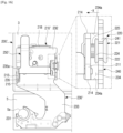
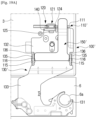
- FIG. 1 is a perspective view illustrating a refrigerator according to an embodiment.
- a refrigerator 1 may include a cabinet 3 and a pair of doors 5 and 6.
- the cabinet 3 forms the appearance of the refrigerator 1.
- the interior space of the cabinet 3 may be divided into a freezer compartment (not illustrated) for freezing food and a refrigerator compartment 7 for refrigerating food.
- a freezer compartment (not illustrated) for freezing food
- a refrigerator compartment 7 for refrigerating food.
- the freezer compartment is provided on the left and the refrigerator compartment 7 is provided on the right.
- the pair of doors that is, a left door 5 and a right door 6 are disposed in the front surface of the cabinet 3.
- the left door 5 is rotatably disposed on the left side of the front surface of the cabinet 3 to selectively open and close the freezer compartment.
- the right door 6 is rotatably disposed on the right side of the front surface of the cabinet 3 to selectively open and close the refrigerator compartment 7.
- each of the left door 5 and the right door 6 may be supported by hinges, so that each of the left door 5 and the right door 6 may be opened and closed with respect to the front surface of the cabinet 3.
- a left hinge 10' may be disposed on the left side of the upper surface of the cabinet 3, so that the left door 5 is opened and closed with respect to the front surface of the cabinet 3.
- a right hinge 10 may be disposed on the right side of the upper surface of the cabinet 3, so that the right door 6 is opened and closed with respect to the front surface of the cabinet 3.
- the left hinge 10' disposed on the upper end of the left door 5 and the right hinge 10 disposed on the upper end of the right door 6 may have the same structure; therefore, the right hinge 10 will be disclosed as an example, hereinafter. However, there is a difference in that the left hinge 10' and the right hinge 10 have a line-symmetric structure. Hereinafter, for convenience of description, the right hinge 10 will be referred to as a hinge.
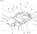
- FIG. 2 is a perspective view illustrating a hinge disposed on an upper end of a refrigerator according to an embodiment.
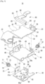
- FIG. 3 is an exploded perspective view illustrating the hinge of FIG. 2 .
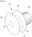
- FIG. 4 is a perspective view illustrating an upper adjustment bolt of FIG. 2 .
- a hinge 10 of an embodiment of the disclosure includes an upper moving part 20, a lower moving part 40, and a fixing part 60.
- the upper moving part 20 may be coupled to the door 6 and may be formed to be movable in a first direction with respect to the cabinet 3.
- One end of the upper moving part 20 may be provided with a cylindrical hinge shaft 21 to be coupled to the door 6.
- a hinge hole 6a into which the hinge shaft 21 is inserted may be provided at the upper end of the door 6. Accordingly, because the door 6 may rotate at a predetermined angle based on the hinge shaft 21, the door 6 may selectively open and close the inner space of the cabinet 3.
- the first direction refers to a direction perpendicular to the front surface of the cabinet 3.
- the upper moving part 20 is disposed on the upper side of the lower moving part 40 disposed in the cabinet 3, and is formed to move linearly in the first direction with respect to the cabinet 3.
- the upper moving part 20 may be formed of a flat plate, and may include a slide portion 22 that is in contact with the lower moving part 40 and slides with respect to the lower moving part 40 and a hinge portion 23 in which the hinge shaft 21 is disposed.
- the hinge portion 23 may be formed by being bent to have a predetermined level difference with respect to the slide portion 22.
- the slide portion 22 and the hinge portion 23 may be formed to be parallel to each other.
- the hinge shaft 21 may be disposed perpendicular to the hinge portion 23.
- the slide portion 22 may be formed in a substantially rectangular flat plate. Both side surfaces of the slide portion 22 may be formed to be parallel to each other. The both side surfaces of the slide portion 22 may form slide surfaces 25 and 26 that are in contact with the lower moving part 40 when the slide portion 22 moves linearly in one direction with respect to the lower moving part 40. In other words, a pair of slide surfaces 25 and 26 may be formed on both side surfaces of the slide portion 22 of the upper moving part 20. Accordingly, the upper moving part 20 may include the pair of upper slide surfaces 25 and 26 formed in the first direction.
- a first lower opening 32 through which a lower fixing portion 61 of the fixing part 60 protrudes may be provided on one side surface 26 of the slide portion 22.
- a second lower opening 33 through which a support portion 65 of the fixing part 60 protrudes may be provided on the opposite side surface 25 of the slide portion 22.
- Each of the first lower opening 32 and the second lower opening 33 may be formed to have a width greater than the width W4 of the lower fixing portion 61 and the width of the support portion 65, so that the upper moving part 20 may move a predetermined distance without interference with the lower fixing portion 61 and the support portion 65.
- the lower moving part 40 is disposed under the upper moving part 20 and may include an upper adjustment member 50 configured to move the upper moving part 20 in the first direction.
- the lower moving part 40 is formed to guide the upper moving part 20 to linearly move in the first direction.
- the lower moving part 40 may be formed to move linearly in a second direction.
- the second direction refers to a direction parallel to the front surface of the cabinet 3. Therefore, the second direction is a direction perpendicular to the first direction.
- a first slide plate (not illustrated) may be disposed between the lower moving part 40 and the upper moving part 20 so that the upper moving part 20 may slide smoothly with respect to the lower moving part 40.
- the lower moving part 40 may be formed in an approximately rectangular flat plate.
- An upper fixing portion 41 may extend vertically from one end of the lower moving part 40.
- An upper bolt hole 42 into which an upper adjustment bolt 51 is fastened may be formed in the upper fixing portion 41.
- a female thread may be formed in the upper bolt hole 42 of the upper fixing portion 41.
- the upper fixing portion 41 may be formed at one end of the lower moving part 40 in the first direction in which the upper moving part 20 moves.
- the upper adjustment bolt 51 may include a head 52, a body 53, and an intermediate ring 54.
- the head 52 may be formed to turn the upper adjustment bolt 51.
- a hexagonal hole 56 into which a hexagonal wrench is inserted may be formed in the surface of the head 52.
- the body 53 may extend vertically from the lower surface of the head 52 and may be formed in a cylindrical shape.
- the lower portion of the body 53 may be provided with a threaded portion 55 on which a male thread is formed.
- the threaded portion 55 may be formed from one end of the body 53 to the intermediate ring 54.
- the threaded portion 55 of the upper adjustment bolt 51 may be formed to be fastened to the upper bolt hole 42 of the upper fixing portion 41. Accordingly, the threaded portion 55 of the upper adjustment bolt 51 may be fastened to the female thread of the upper bolt hole 42 of the upper fixing portion 41.
- the intermediate ring 54 may be formed on the body 53 so as to be spaced apart from the head 52 by a predetermined distance. A space between the intermediate ring 54 and the head 52 may form an engaging groove 57.
- the engaging groove 57 may be formed so that an upper hooking portion 27 of the upper moving part 20 is inserted into the engaging groove 57.
- the upper hooking portion 27 may be formed so that, when the upper hooking portion 27 is inserted into the engaging groove 57 of the upper adjustment bolt 51, the upper hooking portion 27 does not move with respect to the engaging groove 57.
- the upper hooking portion 27 of the upper moving part 20 may be formed at one end of the slide portion 22.
- the upper hooking portion 27 may be formed at one end of the slide portion 22 facing the hinge shaft 21.
- the upper hooking portion 27 may extend vertically from one end of the slide portion 22 of the upper moving part 20, and may be bent so that the upper hooking portion 27 is inserted into the engaging groove 57 of the upper adjustment bolt 51.
- An opening 28 into which the head 52 of the upper adjustment bolt 51 is inserted may be formed under the upper hooking portion 27.
- an upper avoidance opening 30 into which the upper fixing portion 41 of the lower moving part 40 is inserted may be provided in the slide portion 22 in front of the upper hooking portion 27.
- the width W1 (see FIG. 5A ) of the upper avoidance opening 30 of the upper moving part 20 may be formed to be wider than the width W2 (see FIG. 5A ) of the upper fixing portion 41 of the lower moving part 40.
- the depth D1 (see FIG. 5A ) of the upper avoidance opening 30 may be formed to have a size corresponding to a moving distance of the upper moving part 20 in the first direction. Accordingly, the distance in which the upper moving part 20 moves in the first direction may be limited by the depth D1 of the upper avoidance opening 30.
- the upper moving part 20 may move in the first direction with respect to the lower moving part 40.
- the upper hooking portion 27 is formed integrally with the upper moving part 20, when the upper hooking portion 27 is moved, the upper moving part 20 is moved with respect to the lower moving part 40.
- the upper fixing portion 41 and the upper adjustment bolt 51 provided in the lower moving part 40 may form the upper adjustment member 50 capable of moving the upper moving part 20 in the first direction.
- the lower moving part 40 may include a pair of lower guide portions 45 and 46 that guide the pair of the upper slide surfaces 25 and 26 of the upper moving part 20 so that the upper moving part 20 moves linearly in the first direction.
- the lower moving part 40 may include a pair of sidewalls 43 and 44 extending vertically from the both side surfaces thereof, that is, a first sidewall 43 and a second sidewall 44.
- the pair of sidewalls 43 and 44 may extend from both side surfaces of the lower moving part 40 perpendicular to one end of the lower moving part 40 on which the upper fixing portion 41 is formed.
- the pair of lower guide portions 45 and 46 may be formed on the inner surfaces of the pair of sidewalls 43 and 44 of the lower moving part 40.
- the upper moving part 20 may be disposed between the pair of sidewalls 43 and 44 on the upper surface of the lower moving part 40, and may slide along the pair of sidewalls 43 and 44.
- the pair of sidewalls 43 and 44 of the lower moving part 40 may be formed in the first direction, and may face the pair of upper slide surfaces 25 and 26 of the upper moving part 20.
- An insertion protrusion 49 may be formed at one end of the lower moving part 40 on which the upper fixing portion 41 is formed.
- the insertion protrusion 49 may be formed to be spaced apart from the upper fixing portion 41 by a predetermined distance.
- the fixing part 60 is disposed under the lower moving part 40 and is fixed to the cabinet 3.
- the fixing part 60 may include a lower adjustment member 70 for moving the lower moving part 40 in the second direction, and may be formed to guide the lower moving part 40 to linearly move in the second direction.
- the fixing part 60 may be formed in an approximately rectangular flat plate.
- the lower fixing portion 61 may extend vertically from one end of the fixing part 60.
- a lower bolt hole 62 into which a lower adjustment bolt 71 is fastened may be formed in the lower fixing portion 61.
- a female thread may be formed in the lower bolt hole 62 of the lower fixing portion 61.
- the lower fixing portion 61 may be formed at one end of the fixing part 60 in the direction in which the lower moving part 40 moves.
- a first rotation groove 63 into which a first rotation protrusion 83 of a hinge clamp 80 is inserted may be formed on one side surface of the lower fixing portion 61.
- the lower adjustment bolt 71 may include a head 72, a body, and an intermediate ring 74.
- the lower adjustment bolt 71 is formed in the same manner as the upper adjustment bolt 51 described above; therefore, a detailed description thereof is omitted.
- An engaging groove 77 into which a lower hooking portion 47 of the lower moving part 40 is inserted may be formed between the head 72 and the intermediate ring 74 of the lower adjustment bolt 71.
- the lower hooking portion 47 of the lower moving part 40 may be formed on one side surface of the lower moving part 40.
- the lower hooking portion 47 may be formed on one side surface of the lower moving part 40 that is formed at a right angle to one end of the lower moving part 40 on which the upper fixing portion 41 is provided.
- the lower hooking portion 47 may be formed on the second sidewall 44 of the lower moving part 40.
- An opening 48 into which the head 72 of the lower adjustment bolt 71 is inserted may be formed in the lower hooking portion 47.
- the lower hooking portion 47 may extend vertically from one side surface of the lower moving part 40 and may be bent so as to be inserted into the engaging groove 77 of the lower adjustment bolt 71.
- a lower avoidance opening 58 into which the lower fixing portion 61 of the fixing part 60 is inserted may be provided in the lower moving part 40 in front of the lower hooking portion 47.
- the lower avoidance opening 58 may be formed in a rectangular shape.
- the width W3 (see FIG. 6A ) of the lower avoidance opening 58 of the lower moving part 40 may be formed to have a size corresponding to the width W4 (see FIG. 6A ) of the lower fixing portion 61 of the fixing part 60.
- the width W3 of the lower avoidance opening 58 may be determined so that both inner side surfaces 58a of the lower avoidance opening 58 are in contact with and slide with respect to both side surfaces 61a of the lower fixing portion 61.
- the depth D3 (see FIG. 6A ) of the lower avoidance opening 58 may be formed to have a size corresponding to a moving distance of the lower moving part 40 in the second direction. Accordingly, the distance in which the lower moving part 40 moves in the second direction may be limited by the depth D3 of the lower avoidance opening 58.
- the lower moving part 40 may be moved in the second direction with respect to the fixing part 60.
- the lower hooking portion 47 is linearly moved by the lower adjustment bolt 71. Because the lower hooking portion 47 is formed integrally with the lower moving part 40, when the lower hooking portion 47 is moved, the lower moving part 40 is moved with respect to the fixing part 60.
- the lower fixing portion 61 and the lower adjustment bolt 71 provided in the fixing part 60 may form the lower adjustment member 70 capable of moving the lower moving part 40 in the second direction.
- the lower moving part 40 may include a pair of lower slide surfaces 58a formed to be parallel to each other in the second direction.
- the pair of lower slide surfaces 58a may guide the lower moving part 40 to linearly move in the second direction.
- the pair of lower slide surfaces 58a may be formed as both inner side surfaces of the lower avoidance opening 58 of the lower moving part 40.
- the pair of lower slide surfaces 58a may further include lower sub-slide surfaces 59a formed on both inner side surfaces of a guide opening 59 formed in the first sidewall 43 of the lower moving part 40.
- the guide opening 59 of the lower moving part 40 may be formed so that the support portion 65 of the fixing part 60 is inserted.
- the width of the guide opening 59 may be formed to have a size corresponding to the width of the support portion 65 of the fixing part 60.
- the width of the guide opening 59 may be determined so that both inner side surfaces of the guide opening 59 are in contact with and slide with respect to both side surfaces 65a of the support portion 65.
- the fixing part 60 may include a pair of lower guide portions 61a formed to guide the pair of lower slide surfaces 58a so that lower moving part 40 linearly moves in the second direction.
- the pair of lower guide portions 61a of the fixing part 60 may be formed as both side surfaces of the lower fixing portion 61 extending vertically from one side surface of the fixing part 60.
- the fixing part 60 may further include a pair of lower sub-guide portions 65a.
- the pair of lower sub-guide portions 65a may be formed as both side surfaces of the support portion 65 extending vertically from one side surface of the fixing part 60.
- the support portion 65 may be formed on the fixing part 60 to be parallel to the lower fixing portion 61 and to face the lower fixing portion 61. Both side surfaces of the support portion 65 may be formed to slide in contact with the pair of lower sub-slide surfaces 59a provided on both inner side surfaces of the guide opening 59 of the lower moving part 40.
- a second rotation groove 66 into which a second rotation protrusion 84 of the hinge clamp 80 is inserted may be provided on one side surface of the support portion 65.
- a fixing wall 68 may be formed on one side surface of the fixing part 60, that is, on one side surface of the fixing part 60 perpendicular to the lower fixing portion 61.
- the fixing wall 68 may extend vertically from one side surface of the fixing part 60.
- An insertion groove 69 into which the insertion protrusion 49 of the lower moving part 40 is inserted may be formed at a lower portion of the fixing wall 68.
- the width of the insertion groove 69 may be formed larger than the width of the insertion protrusion 49. Accordingly, when the lower moving part 40 moves in the second direction, the insertion protrusion 49 does not interfere with the insertion groove 69 of the fixing part 60.
- the hinge 10 may further include the hinge clamp 80.
- the hinge clamp 80 may be formed to fix the upper moving part 20 and the lower moving part 40 to the fixing part 60.
- the hinge clamp 80 may include a pressing portion 81 and a handle 82.
- a pair of rotation protrusions that is, a first rotation protrusion 83 and a second rotation protrusion 84 may be provided at both ends of the pressing portion 81.
- the first rotation protrusion 83 may be formed to be inserted into the first rotation groove 63 of the lower fixing portion 61 of the fixing part 60
- the second rotation protrusion 84 may be formed to be inserted into the second rotation groove 66 of the support portion 65 of the fixing part 60.
- the pressing portion 81 may rotate based on the pair of rotation protrusions 83 and 84 inserted into the first rotation groove 63 and the second rotation groove 66 of the fixing part 60.
- the lower end 85 of the pressing portion 81 may be formed to press the upper surface of the upper moving part 20.
- the handle 82 may extend approximately vertically from the pressing portion 81. The user may rotate the pressing portion 81 while holding the handle 82.
- the upper moving part 20 and the lower moving part 40 are fixed and do not move.
- the upper moving part 20 and the lower moving part 40 may be moved by the upper adjustment member 50 and the lower adjustment member 70.
- FIGS. 5A , 5B , 6A , and 6B the operation of the hinge 10 will be described in detail with reference to FIGS. 5A , 5B , 6A , and 6B .
- FIG. 5A is a plan view illustrating a hinge according to an embodiment
- FIG. 5B is a plan view illustrating a state in which an upper moving part of the hinge of FIG. 5A is moved in a first direction.
- a bottom surface 30b of the upper avoidance opening 30 of the upper moving part 20 is in contact with the front surface of the upper fixing portion 41 of the lower moving part 40.
- the threaded portion 55 of the upper adjustment bolt 51 is moved in the Y direction with respect to the upper bolt hole 42 of the upper fixing portion 41.
- the upper hooking portion 27 of the upper moving part 20 is inserted into the engaging groove 57 of the upper adjustment bolt 51, when the upper adjustment bolt 51 moves in the Y direction, the upper hooking portion 27 is moved in the Y direction together with the upper adjustment bolt 51. Because the upper hooking portion 27 is formed integrally with the upper moving part 20, when the upper adjustment bolt 51 moves, the upper moving part 20 moves together in the Y direction. In other words, when the upper adjustment bolt 51 is rotated in one direction, the upper moving part 20 is moved in the Y direction.
- the pair of upper slide surfaces 25 and 26 are formed on both side surfaces of the upper moving part 20, and the pair of upper guide portions 45 and 46 corresponding to the pair of upper slide surfaces 25 and 26 are formed on the lower moving part 40. Therefore, the movement of the upper moving part 20 in the Y direction is guided by the pair of upper slide surfaces 25 and 26 of the upper moving part 20 and the pair of upper guide portions 45 and 46 of the lower moving part 40. Because the pair of upper slide surfaces 25 and 26 of the upper moving part 20 and the pair of upper guide portions 45 and 46 of the lower moving part 40 are formed to be parallel to each other, when the upper adjustment bolt 51 is rotated in one direction, the upper moving part 20 may be linearly moved in the Y direction with respect to the lower moving part 40.
- the intermediate ring 54 of the upper adjustment bolt 51 comes in contact with the rear surface of the upper fixing portion 41 of the lower moving part 40 as illustrated in FIG. 5B .
- the upper moving part 20 may no longer move in the Y direction.
- the upper adjustment bolt 51 When the upper adjustment bolt 51 is rotated in the opposite direction in the state of FIG. 5B , the upper adjustment bolt 51 may be moved in the - Y direction with respect to the upper fixing portion 41. At this time, the upper moving part 20 is moved in the - Y direction together with the upper adjustment bolt 51.
- the user may rotate the upper adjustment bolt 51 to move the door 6 coupled to the hinge shaft 21 of the upper moving part 20 in the Y direction.
- FIG. 6A is a plan view illustrating a hinge according to an embodiment
- FIG. 6B is a plan view illustrating a state in which a lower moving part of the hinge of FIG. 6A is moved in a second direction.
- the bottom surface 58b of the lower avoidance opening 58 of the lower moving part 40 is in contact with the front surface of the lower fixing portion 61 of the fixing part 60.
- the threaded portion 75 of the lower adjustment bolt 71 is moved in the X direction with respect to the bolt hole 62 of the lower fixing portion 61.
- the lower hooking portion 47 of the lower moving part 40 is inserted into the engaging groove 77 of the lower adjustment bolt 71, when the lower adjustment bolt 71 moves in the X direction, the lower hooking portion 47 is moved in the X direction together with the lower adjustment bolt 71. Because the lower hooking portion 47 is formed integrally with the lower moving part 40, when the lower adjustment bolt 71 moves, the lower moving part 40 moves together in the X direction. In other words, when the lower adjustment bolt 71 is rotated in one direction, the lower moving part 40 is moved in the X direction.
- the pair of lower slide surfaces 58a are formed on both inner side surfaces of the lower avoidance opening 58 of the lower moving part 40, and the pair of lower sub-slide surfaces 59a are formed on both inner side surfaces of the guide opening 59.
- the fixing part 60 is provided with the pair lower guide portions 61a corresponding to the pair of the lower slide surfaces 58a and the pair of lower sub-guide portions 65a corresponding to the pair of lower sub-slide surfaces 59a. Accordingly, the movement of the lower moving part 40 in the X direction is guided by the pair of lower slide surfaces 58a and the lower sub-slide surfaces 59a of the lower moving part 40 and the pair of lower guide portions 61a and the pair of lower sub-guide portions 65a of the fixing part 60.
- the lower moving part 40 may be linearly moved in the X direction with respect to the fixing part 60.
- the upper moving part 20 is disposed on the upper surface of the lower moving part 40, when the lower moving part 40 is moved in the X direction by the lower adjustment bolt 71, the upper moving part 20 is also moved in the X direction together with the lower moving part 40.
- the lower adjustment bolt 71 When the lower adjustment bolt 71 is rotated in the opposite direction in the state of FIG. 6B , the lower adjustment bolt 71 may be moved in the opposite direction with respect to the lower fixing portion 61, that is, in the - X direction. At this time, the lower moving part 40 is moved in the - X direction together with the lower adjustment bolt 71.
- the user may rotate the lower adjustment bolt 71 to move the door 6 coupled to the hinge shaft 21 of the upper moving part 20 in the X direction.
- the left door and the right door disposed in a refrigerator using a hinge may adjust a level difference and a gap therebetween.
- FIG. 7 is a view for explaining a method of adjusting a level difference and a gap between a left door and a right door using a hinge according to an embodiment.
- the left door 5 and the right door 6 may be adjusted so that there is no level difference between the left door 5 and the right door 6.
- the level difference G1 between the left door 5 and the right door 6 may be made zero (0).
- the front surface of the right door 6 may form a single plane with the front surface of the left door 5.
- the left door 5 and the right door 6 may be adjusted so that the gap G2 between the left door 5 and the right door 6 is uniform.
- the gap G1 between the left door 5 and the right door 6 may be made to be constant in the height direction of the refrigerator 1.
- the gap G2 between the side surface of the right door 6 and the side surface of the left door 5 may be adjusted to be uniform.
- FIG. 8 is a plan view illustrating a refrigerator according to another embodiment.
- a refrigerator 1 may include a cabinet 3 and a pair of doors 5 and 6.
- the cabinet 3 forms the appearance of the refrigerator 1.
- the interior space of the cabinet 3 may be divided into a freezer compartment and a refrigerator compartment.
- the pair of doors that is, a left door 5 and a right door 6 may be disposed in the front surface of the cabinet 3.
- each of the left door 5 and the right door 6 may be supported by hinges 100 and 200, so that each of the left door 5 and the right door 6 may be opened and closed with respect to the front surface of the cabinet 3.
- a left hinge 100 is disposed on the left side of the upper surface of the cabinet 3 to support the left door 5 so that the left door 5 is rotated with respect to the cabinet 3.
- the left hinge 100 may allow the left door 5 to be opened and closed with respect to the front surface of the cabinet 3.
- the left hinge 100 is formed to move the left door 5 in a direction (Y direction) perpendicular to the front surface of the cabinet 3.
- a right hinge 200 is disposed on the right side of the upper surface of the cabinet 3 to support the right door 6 so that the right door 6 is rotated with respect to the cabinet 3.
- the right hinge 200 may allow the right door 6 to be opened and closed with respect to the front surface of the cabinet 3.
- the right hinge 200 is formed to move the right door 6 in a direction (X direction) parallel to the front surface of the cabinet 3.
- FIG. 9 is a plan view illustrating a left hinge of the refrigerator of FIG. 8
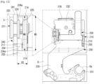
- FIG. 10 is an exploded perspective view illustrating the left hinge of FIG. 9 .
- the left hinge 100 includes a left fixing part 110 and a vertical moving part 130.
- the left fixing part 110 is fixed to the cabinet 3 and supports the vertical moving part 130 so that the vertical moving part 130 may move.
- the left fixing part 110 is disposed under the vertical moving part 130 and is fixed to the upper surface of the cabinet 3.
- the left fixing part 110 includes a vertical adjustment member 120 configured to move the vertical moving part 130 in a direction perpendicular to the front surface of the cabinet 3 (hereinafter referred to as a vertical direction) (arrow Y).
- the left fixing part 110 may guide the vertical moving part 130 to linearly move in the vertical direction.
- the left fixing part 110 may be formed in an approximately rectangular flat plate.
- a vertical fixing portion 111 may extend vertically from one end of the left fixing part 110.
- the vertical fixing portion 111 may be provided with a vertical groove 112 in which a vertical adjustment bolt 121 is disposed.
- the vertical groove 112 may be formed at the upper end of the vertical fixing portion 111, and both sidewalls 112a of the vertical groove 112 may be inserted into an engaging groove 127 of the vertical adjustment bolt 121 so that the vertical adjustment bolt 121 may rotate with respect to the vertical fixing portion 111. Accordingly, the vertical adjustment bolt 121 may rotate with respect to the vertical groove 112 of the vertical fixing portion 111 without moving back and forth, left and right with respect to the left fixing part 110.
- the vertical fixing portion 111 may be formed at one end of the left fixing part 110 in the direction in which the vertical moving part 130 moves.
- the vertical adjustment bolt 121 may include a head 122, a body 123, and an intermediate ring 124.
- the vertical adjustment bolt 121 may be formed in the same manner as the upper adjustment bolt 51 and the lower adjustment bolt 71 of the above-described embodiment, and thus a detailed description thereof is omitted.
- the engaging groove 127 into which the vertical fixing portion 111 of the left fixing part 110 is inserted may be formed between the head 122 and the intermediate ring 124 of the vertical adjustment bolt 121.
- An insertion opening 113 into which an insertion protrusion 139 of the vertical moving part 130 is inserted may be formed at one side of the vertical groove 112 in the vertical fixing portion 111.
- the width of the insertion opening 113 may be formed larger than the width of the insertion protrusion 139. Therefore, when the vertical moving part 130 moves in the vertical direction, the insertion protrusion 139 does not interfere with the insertion opening 113 of the left fixing part 110.
- a pair of support portions 115 may be formed on both side surfaces of the left fixing part 110 perpendicular to the vertical fixing portion 111.
- the pair of support portions 115 may extend vertically from both side surfaces of the left fixing part 110.
- the pair of support portions 115 may be formed to face each other in parallel.
- the vertical moving part 130 may be disposed between the pair of support portions 115.
- the inner surfaces of the pair of support portions 115 facing each other may form guide surfaces 116 that guide the vertical moving part 130. Accordingly, the pair of guide surfaces 116 of the left fixing part 110 may guide the linear movement of the vertical moving part 130.
- a rotation groove 117 into which a rotation protrusion 153 of a hinge clamp 150 is inserted may be formed on one side surface of each of the pair of support portions 115.
- the hinge clamp 150 may rotate based on the pair of rotation grooves 117.
- the vertical moving part 130 may be coupled to the left door 5, and may be formed to move in the vertical direction (arrow Y) with respect to the cabinet 3.
- One end of the vertical moving part 130 may be provided with a cylindrical hinge shaft 131 coupled to the left door 5.
- a hinge hole 5a into which the hinge shaft 131 is inserted may be provided at the upper end of the left door 5. Accordingly, because the left door 5 may rotate at a predetermined angle based on the hinge shaft 131, the left door 5 may selectively open and close the left side of the front surface of the cabinet 3.
- the vertical moving part 130 may be disposed on the upper side of the left fixing part 110 fixed to the cabinet 3, and may be formed to move linearly in the vertical direction with respect to the cabinet 3.
- the vertical moving part 130 may be formed of a flat plate, and may include a vertical slide portion 132 that is in contact with the left fixing part 110 and slides with respect to the left fixing part 110 and a vertical hinge portion 133 in which the hinge shaft 131 is disposed.
- the vertical hinge portion 133 may be formed by being bent to have a predetermined level difference with respect to the vertical slide portion 132.
- the vertical slide portion 132 and the vertical hinge portion 133 may be formed to be parallel to each other.
- the hinge shaft 131 may be disposed perpendicular to the vertical hinge portion 133.
- the vertical slide portion 132 may be formed in a substantially rectangular flat plate.
- a pair of vertical slide surfaces 136 may be formed on both side surfaces of the vertical slide portion 132 of the vertical moving part 130.
- the pair of vertical slide surfaces 136 may be formed to be parallel to each other on both side surfaces of the vertical slide portion 132, and may be in contact with the left fixing part 110 when the vertical slide portion 132 moves linearly in one direction with respect to the left fixing part 110.
- the pair of vertical slide surfaces 136 may be formed as bottom surfaces of a pair of moving grooves 135 formed on both side surfaces of the vertical slide portion 132.
- the vertical moving part 130 may include the pair of vertical slide surfaces 136 formed in parallel in a direction perpendicular to the front surface of the cabinet 3.
- a vertical connection portion 140 of the vertical moving part 130 may be formed at one end of the vertical slide portion 132.
- the vertical connection portion 140 may be formed at one end of the vertical slide portion 132 facing the hinge shaft 131.
- the vertical connection portion 140 may extend vertically from one end of the vertical slide portion 132 of the vertical moving part 130, and may include a bolt hole 141 into which the male thread 125 of the vertical adjustment bolt 121 is fastened.
- a female thread corresponding to the male thread 125 of the vertical adjustment bolt 121 may be formed on the inner surface of the bolt hole 141.
- the vertical connection portion 140 of the vertical moving part 130 faces the vertical fixing portion 111 of the left fixing part 110.
- the engaging groove 127 of the vertical adjustment bolt 121 is coupled to the insertion groove 112 of the vertical fixing portion 111
- the male thread 125 of the vertical adjustment bolt 121 may be fastened to the bolt hole 141 of the vertical connection portion 140 of the vertical moving part 130.
- the vertical moving part 130 may be moved in the longitudinal direction of the vertical adjustment bolt 121, that is, in the Y direction. Depending on the rotation direction of the vertical adjustment bolt 121, the vertical moving part 130 may approach the vertical fixing portion 111 of the left fixing part 110 or move away from the vertical fixing portion 111.
- the vertical fixing portion 111 and the vertical adjustment bolt 121 provided on the left fixing part 110 may form the vertical adjustment member 120 capable of moving the vertical moving part 130 in the vertical direction.
- the left fixing part 110 may include a pair of vertical guide surfaces 116 for guiding the pair of vertical slide surfaces 136 of the vertical moving part 130 so that the vertical moving part 130 linearly moves in the vertical direction.
- the pair of the vertical guide surfaces 116 may be formed as the inner surfaces of the pair of support portions 115 formed on both side surfaces of the left fixing part 110.
- the vertical moving part 130 may be disposed between the pair of support portions 115 on the upper surface of the left fixing part 110, and may move along the pair of support portions 115.
- the pair of support portions 115 of the left fixing part 110 may be formed in a direction perpendicular to the front surface of the cabinet 3, and may face the pair of vertical slide surfaces 136 of the vertical moving part 130.
- the left hinge 100 may further include a hinge clamp 150.
- the hinge clamp 150 may be formed to fix the vertical moving part 130 to the left fixing part 110.
- the hinge clamp 150 may include a pressing portion 151 and a handle 152.
- a pair of rotation protrusions 153 may be provided at both ends of the pressing portion 151.
- the pair of rotation protrusions 153 may be formed to be inserted into a pair of rotation grooves 117 of the pair of support portions 115 of the left fixing part 110. Accordingly, the pressing portion 151 may rotate based on the pair of rotation protrusions 153 inserted into the pair of rotation grooves 117 of the left fixing part 110.
- the lower end of the pressing portion 151 may be formed to press the upper surface of the vertical moving part 130.
- the handle 152 may extend approximately vertically from the pressing portion 151. The user may rotate the pressing portion 151 while holding the handle 152.
- the vertical moving part 130 When the lower end of the pressing portion 151 presses the upper surface of the vertical moving part 130, the vertical moving part 130 is fixed to the left fixing part 110 and does not move. When the lower end of the pressing portion 151 does not contact the upper surface of the vertical moving part 130, the vertical moving part 130 may be moved by the vertical adjustment member 120.
- FIGS. 11A and 11B are views for explaining an operation of a vertical moving part of a left hinge.
- the rear surface of the vertical connection portion 140 of the vertical moving part 130 is in contact with the intermediate ring 124 of the vertical adjustment bolt 121 coupled to the vertical fixing portion 111 of the left fixing part 110.
- the vertical connection portion 140 fastened to the threaded portion 125 of the vertical adjustment bolt 121 is moved in the longitudinal direction of the vertical adjustment bolt 121, that is, in the Y direction.
- the vertical connection portion 140 is integrally formed with the vertical moving part 130, when the vertical connection portion 140 is moved, the vertical moving part 130 is moved along with the vertical connection portion 140 in the Y direction. In other words, when the vertical adjustment bolt 121 is rotated in one direction, the vertical moving part 130 is moved in the Y direction.
- the pair of vertical slide surfaces 136 are formed on both side surfaces of the vertical moving part 130, and the pair of vertical guide surfaces 116 corresponding to the pair of vertical slide surfaces 136 are provided in the left fixing part 110. Accordingly, the Y-direction movement of the vertical moving part 130 is guided by the pair of vertical slide surfaces 136 of the vertical moving part 130 and the pair of vertical guide surfaces 116 of the left fixing part 110. Because the pair of vertical slide surfaces 136 of the vertical moving part 130 and the pair of vertical guide surfaces 116 of the left fixing part 110 are formed to be parallel to each other, when the vertical adjustment bolt 121 is rotated in one direction, the vertical moving part 130 may be linearly moved in the Y direction with respect to the left fixing part 110.
- the vertical moving part 130 coupled to the vertical adjustment bolt 121 may be moved in the - Y direction with respect to the left fixing part 110.
- the vertical adjustment bolt 121 When the vertical adjustment bolt 121 is rotated to the maximum in the opposite direction, the rear surface of the vertical connection portion 140 of the vertical moving part 130 comes into contact with the intermediate ring 124 of the vertical adjustment bolt 121 as illustrated in FIG. 11A . When this state is reached, the vertical moving part 130 may no longer move in the - Y direction.
- the user may rotate the vertical adjustment bolt 121 to move the left door 5 coupled to the hinge shaft 131 of the vertical moving part 130 in the Y direction.
- FIG. 12 is a plan view illustrating a right hinge of the refrigerator of FIG. 8
- FIG. 13 is an exploded perspective view illustrating the right hinge of FIG. 12 .
- the right hinge 200 includes a right fixing part 210 and a horizontal moving part 230.
- the right fixing part 210 is fixed to the cabinet 3 and supports the horizontal moving part 230 so that the horizontal moving part 230 may move.
- the right fixing part 210 is disposed under the horizontal moving part 230 and is fixed to the upper surface of the cabinet 3.
- the right fixing part 210 includes a horizontal adjustment member 220 configured to move the horizontal moving part 230 in a direction parallel to the front surface of the cabinet 3 (hereinafter referred to as a horizontal direction), that is, in the X direction.
- the right fixing part 210 may guide the horizontal moving part 230 to linearly move in the horizontal direction.
- the right fixing part 210 may be formed in an approximately rectangular flat plate.
- a horizontal fixing portion 211 may extend vertically from one end of the right fixing part 210.
- the horizontal fixing portion 211 may be provided with a bolt hole 212 into which a horizontal adjustment bolt 221 is fastened.
- a female thread is formed in the bolt hole 212 of the horizontal fixing portion 211.
- the horizontal fixing portion 211 may be formed at one end of the right fixing part 210 in the direction in which the horizontal moving part 230 moves.
- a first rotation groove 216 into which a first rotation protrusion 253 of a hinge clamp 250 is inserted may be formed on one side surface of the horizontal fixing portion 211.
- the horizontal adjustment bolt 221 may include a head 222, a body 223, and an intermediate ring 224.
- the horizontal adjustment bolt 221 may be formed in the same manner as the upper adjustment bolt 51 and the lower adjustment bolt 71 of the hinge 10 of the above-described embodiment, and thus a detailed description thereof is omitted.
- An engaging groove 227 into which the horizontal hooking portion of the horizontal moving part 230 is inserted may be formed between the head 222 and the intermediate ring 224 of the horizontal adjustment bolt 221.
- the horizontal fixing portion 211 and the horizontal adjustment bolt 221 provided on the right fixing part 210 may form the horizontal adjustment member capable of moving the horizontal moving part 230 in the horizontal direction.
- the right fixing part 210 may include a support portion 213.
- the support portion 213 may extend vertically from the other end of the right fixing part 210 and may be formed to face the horizontal fixing portion 211.
- a second rotation groove 217 into which a second rotation protrusion 254 of the hinge clamp 250 is inserted may be provided on one side surface of the support portion 213.
- the horizontal moving part 230 may be disposed between the horizontal fixing portion 211 and the support portion 213 on the right fixing part 210.
- a fixing wall 218 may be formed on one side surface of the right fixing part 210, that is, on one side surface of the right fixing part 210 perpendicular to the horizontal fixing portion 211.
- the fixing wall 218 may extend vertically from one side surface of the right fixing part 210.
- An insertion groove 219 into which an insertion protrusion 239 of the horizontal moving part 230 is inserted may be formed at a lower portion of the fixing wall 218.
- the width of the insertion groove 219 may be formed larger than the width of the insertion protrusion 239. Accordingly, when the horizontal moving part 230 moves in the horizontal direction, the insertion protrusion 239 does not interfere with the insertion groove 219 of the right fixing part 210.
- the right fixing part 210 may include a pair of horizontal guide portions 214 for guiding a pair of horizontal slide surfaces 234a of the horizontal moving part 230 so that the horizontal moving part 230 linearly moves in the horizontal direction.
- the pair of horizontal guide portions 214 of the right fixing part 210 may be formed as both side surfaces of the horizontal fixing portion 211 extending vertically from one end of the right fixing part 210.
- the right fixing part 210 may further include a pair of horizontal sub-guide portions 215.
- the pair of horizontal sub-guide portions 215 may be formed as both side surfaces of the support portion 213 extending vertically from the other end of the right fixing part 210. Both side surfaces of the support portion 213 may be formed to slide in contact with both inner side surfaces of the guide opening 235 of the horizontal moving part 230, that is, a pair of horizontal sub-slide surfaces 235a.
- the horizontal moving part 230 may be coupled to the right door 6, and may be formed to move in the horizontal direction with respect to the cabinet 3.
- a hinge shaft 231 having a cylindrical shape coupled to the right door 6 may be provided at one end of the horizontal moving part 230.
- a hinge hole 6a into which the hinge shaft 231 is inserted may be provided at the upper end of the right door 6. Accordingly, because the right door 6 may rotate at a predetermined angle based on the hinge shaft 231, the right door 6 may selectively open and close the right side of the front surface of the cabinet 3.
- the horizontal moving part 230 may be disposed on the upper side of the right fixing part 210 fixed to the cabinet 3, and may be formed to move linearly in a direction parallel to the cabinet 3.
- the horizontal moving part 230 may be formed of a flat plate, and may include a horizontal slide portion 232 that is in contact with the right fixing part 210 and slides with respect to the right fixing part 210 and a horizontal hinge portion 233 in which the hinge shaft 231 is disposed.
- the horizontal hinge portion 233 may be formed by being bent to have a predetermined level difference with respect to the horizontal slide portion 232.
- the horizontal slide portion 232 and the horizontal hinge portion 233 may be formed to be parallel to each other.
- the hinge shaft 231 may be disposed perpendicular to the horizontal hinge portion 233.
- the horizontal moving part 230 may include a horizontal hooking portion 240.
- the horizontal hooking portion 240 of the horizontal moving part 230 may be formed at one end of the horizontal moving part 230.
- the horizontal hooking portion 240 may be formed at one end of the horizontal moving part 230 adjacent to the horizontal fixing portion 211 of the right fixing part 210.
- the horizontal hooking portion 240 may be formed in two hooking arms 241 extending vertically from one end of the horizontal moving part 230.
- the two hooking arms 241 may be spaced apart from each other by a predetermined distance, and may be formed to be inclined at a predetermined angle to form an approximate isosceles triangle.
- the upper portions of the two hooking arms 241 are inserted into the engaging groove 227 of the horizontal adjustment bolt 221 to fix the horizontal adjustment bolt 221 so that the horizontal adjustment bolt 221 does not move in the longitudinal direction.
- An opening 242 into which the head 222 of the horizontal adjustment bolt 221 is inserted may be provided under the two hooking arms 241.
- an avoidance opening 234 into which the horizontal fixing portion 211 of the right fixing part 210 is inserted may be provided in the horizontal slide portion 232 of the horizontal moving part 230 in front of the horizontal hooking portion 240.
- the avoidance opening 234 may be formed in a rectangular shape.
- the width W5 of the avoidance opening 234 of the horizontal moving part 230 may be formed to have a size corresponding to the width W6 of the horizontal fixing portion 211 of the right fixing part 210.
- the width W5 of the avoidance opening 234 may be determined so that the both inner side surfaces of the avoidance opening 234, that is, the pair of horizontal slide surfaces 234a may slide in contact with the both side surfaces of the horizontal fixing portion 211, that is, the pair of horizontal guide portions 214.
- the depth D5 of the avoidance opening 234 may be formed to have a size corresponding to a moving distance of the horizontal moving part 230 in the horizontal direction. Accordingly, the distance in which the horizontal moving part 230 moves in the horizontal direction may be limited by the depth D5 of the avoidance opening 230.
- the horizontal moving part 230 may be moved in the horizontal direction with respect to the right fixing part 210.
- the horizontal hooking portion 240 is linearly moved by the horizontal adjustment bolt 221. Because the horizontal hooking portion 240 is formed integrally with the horizontal moving part 230, when the horizontal hooking portion 240 is moved, the horizontal moving part 230 is moved with respect to the right fixing part 210.
- the horizontal moving part 230 may include the pair of horizontal slide surfaces 234a formed in parallel in the horizontal direction.
- the pair of horizontal slide surfaces 234a may be formed to guide the horizontal moving part 230 to linearly move in the horizontal direction.
- the pair of horizontal slide surfaces 234a may be formed as both inner side surfaces of the avoidance opening 234 of the horizontal moving part 230.
- the pair of horizontal slide surfaces 234a may further include a pair of horizontal sub-slide surfaces 235a formed on both inner side surfaces of a guide opening 235 formed at the other end of the horizontal moving part 230.
- the guide opening 235 of the horizontal moving part 230 may be formed so that the support portion 213 of the right fixing part 210 is inserted into the guide opening 235.
- the width of the guide opening 235 may be formed to have a size corresponding to the width of the support portion 213 of the right fixing part 210.
- the width of the guide opening 235 may be determined so that both inner side surfaces of the guide opening 235, that is, the pair of horizontal sub-slide surfaces 235a may slide in contact with both side surfaces of the support portion 213, that is, the pair of horizontal sub-guide portions 215.
- the right hinge 200 may further include the hinge clamp 250.
- the hinge clamp 250 may be formed to fix the horizontal moving part 230 to the right fixing part 210.
- the hinge clamp 250 may include a pressing portion 251 and a handle 252.
- a pair of rotation protrusions that is, a first rotation protrusion 253 and a second rotation protrusion 254 may be provided at both ends of the pressing portion 251.
- the first rotation protrusion 253 may be formed to be inserted into the first rotation groove 216 of the horizontal fixing portion 211 of the right fixing part 210
- the second rotation protrusion 254 may be formed to be inserted into the second rotation groove 217 of the support portion 213.
- the pressing portion 251 may rotate based on the first and second rotation protrusions 253 and 254 inserted into the first and second rotation grooves 216 and 217 of the right fixing part 210.
- the lower end of the pressing portion 251 may be formed to press the upper surface of the horizontal moving part 230.
- the handle 252 may extend approximately vertically from the pressing portion 251. The user may rotate the pressing portion 251 while holding the handle 252.
- the horizontal moving part 230 When the lower end of the pressing portion 251 presses the upper surface of the horizontal moving part 230, the horizontal moving part 230 is fixed to the right fixing part 210, and thus does not move. When the lower end of the pressing portion 251 does not contact the upper surface of the horizontal moving part 230, the horizontal moving part 230 may be moved by the horizontal adjusting member 220.
- FIGS. 14A and 14B are views for explaining an operation of a horizontal moving part of a right hinge.
- the bottom surface 234b of the avoidance opening 234 of the horizontal moving part 230 is in contact with the front surface of the horizontal fixing portion 211 of the right fixing part 210.
- the threaded portion 225 of the horizontal adjustment bolt 221 is moved in the X direction with respect to the bolt hole 212 of the horizontal fixing portion 211.
- the horizontal hooking portion 240 of the horizontal moving part 230 is inserted into the engaging groove 227 of the horizontal adjustment bolt 221, when the horizontal adjustment bolt 221 moves in the X direction, the horizontal hooking portion 240 is moved in the X direction together with the horizontal adjustment bolt 221. Because the horizontal hooking portion 240 is formed integrally with the horizontal moving part 230, when the horizontal adjustment bolt 221 moves, the horizontal moving part 230 moves together in the X direction. In other words, when the horizontal adjustment bolt 221 is rotated in one direction, the horizontal moving part 230 is moved in the X direction.
- the pair of horizontal slide surfaces 234a are formed on both inner side surfaces of the avoidance opening 234 of the horizontal moving part 230, and the pair of horizontal sub-slide surfaces 235a are formed on both inner side surfaces of the guide opening 235.
- the right fixing part 210 is provided with the pair of horizontal guide portions 214 corresponding to the pair of the horizontal slide surfaces 234a and the pair of horizontal sub-guide portions 215 corresponding to the pair of horizontal sub-slide surfaces 235a.
- the X-direction movement of the horizontal moving part 230 is guided by the pair of horizontal slide surfaces 234a and the horizontal sub-slide surfaces 235a of the horizontal moving part 230 and the pair of horizontal guide portions 214 and the pair of horizontal sub-guide portions 215 of the right fixing part 210. Because the pair of horizontal slide surfaces 234a and the horizontal sub-slide surfaces 235a of the horizontal moving part 230 and the pair of horizontal guide portions 214 and the pair of horizontal sub-guide portions 215 of the right fixing part 210 are formed in parallel to each other, when the horizontal adjustment bolt 221 is rotated in one direction, the horizontal moving part 230 may be linearly moved in the X direction with respect to the right fixing part 210.
- the intermediate ring 224 of the horizontal adjustment bolt 221 comes into contact with the rear surface of the horizontal fixing portion 211 as illustrated in FIG. 14B .
- the horizontal moving part 230 may no longer move in the X direction.
- the horizontal adjustment bolt 221 When the horizontal adjustment bolt 221 is rotated in the opposite direction in the state of FIG. 14B , the horizontal adjustment bolt 221 may be moved in the opposite direction with respect to the horizontal fixing portion 211, that is, in the - X direction. At this time, the horizontal moving part 230 is moved in the - X direction together with the horizontal adjustment bolt 221.
- the horizontal moving part 230 When the horizontal moving part 230 is rotated to the maximum in the opposite direction, the bottom surface 234b of the avoidance opening 234 of the horizontal moving part 230 comes into contact with the front surface of the horizontal fixing portion 211 as illustrated in FIG. 14A . When this state is reached, the horizontal moving part 230 may no longer move in the - X direction.
- the user may rotate the horizontal adjustment bolt 221 to move the right door 6 coupled to the hinge shaft 231 of the horizontal moving part 230 in the X direction.
- the level difference between the left door 5 and the right door 6 may be removed by adjusting the vertical adjustment bolt 121 of the left hinge 100 that may move the left door 5 in a direction perpendicular to the front surface of the cabinet 3.
- the gap between the left door 5 and the right door 6 may be adjusted by using the horizontal adjustment bolt 221 of the right hinge 200 that may move the right door 6 in a direction parallel to the front surface of the cabinet 3.
- a refrigerator 1 may include a cabinet 3 and a pair of doors 5 and 6.
- the cabinet 3 forms the appearance of the refrigerator 1.
- the interior space of the cabinet 3 may be divided into a freezer compartment and a refrigerator compartment.
- the pair of doors that is, a left door 5 and a right door 6, may be disposed in the front surface of the cabinet 3.
- each of the left door 5 and the right door 6 may be supported by hinges, so that each of the left door 5 and the right door 6 may be opened and closed with respect to the front surface of the cabinet 3.
- a left hinge 200' may be disposed on the left side of the upper surface of the cabinet 3 to support the left door 5 so that the left door 5 is rotated with respect to the cabinet 3.
- the left hinge 200' may allow the left door 5 to be opened and closed with respect to the front surface of the cabinet 3.
- the left hinge 200' may be formed to move the left door 5 in a direction (X direction) parallel to the front surface of the cabinet 3.
- a right hinge 100' may be disposed on the right side of the upper surface of the cabinet 3 to support the right door 6 so that the right door 6 is rotated with respect to the cabinet 3.
- the right hinge 100' may allow the right door 6 to be opened and closed with respect to the front surface of the cabinet 3.
- the right hinge 100' may be formed to move the right door 6 in a direction (Y direction) perpendicular to the front surface of the cabinet 3.
- FIG. 16 is a plan view illustrating a left hinge of the refrigerator of FIG. 15 .
- the left hinge 200' may include a left fixing part 210' and a horizontal moving part 230'.
- the left fixing part 210' may be fixed to the cabinet 3 and may support the horizontal moving part 230' so that the horizontal moving part 230' may move.
- the left fixing part 210' may be disposed under the horizontal moving part 230' and may be fixed to the upper surface of the cabinet 3.
- the left fixing part 210' may include a horizontal adjustment member 220 configured to move the horizontal moving part 230' in a direction parallel to the front surface of the cabinet 3 (hereinafter referred to as a horizontal direction), that is, in the X direction.
- the left fixing part 210' may guide the horizontal moving part 230' to linearly move in the horizontal direction.
- the left fixing part 210' may be formed in an approximately rectangular flat plate. Like the right fixing part 210 of the above-described embodiment, the left fixing part 210' may have a horizontal fixing portion 211, a horizontal adjustment bolt 221, a support portion 213, a fixing wall 218, a pair of horizontal guide portions 214, and a pair of horizontal sub-guide portions 215. However, the left fixing part 210' according to this embodiment is different from the right fixing part 210 according to the above-described embodiment in a line-symmetric relationship.
- the horizontal moving part 230' may be coupled to the left door 5 and may be formed to move in the horizontal direction with respect to the cabinet 3.
- a hinge shaft 231 having a cylindrical shape coupled to the left door 5 may be provided at one end of the horizontal moving part 230'.
- a hinge hole 5a into which the hinge shaft 231 is inserted may be provided at the upper end of the left door 5. Accordingly, because the left door 5 may rotate at a predetermined angle based on the hinge shaft 231, the left door 5 may selectively open and close the left side of the front surface of the cabinet 3.
- the horizontal moving part 230' may be disposed on the upper side of the left fixing part 210' fixed to the cabinet 3, and may be formed to move linearly in a direction parallel to the cabinet 3.
- the horizontal moving part 230' may be formed of a flat plate, and may include a horizontal slide portion 232 that slides with respect to the left fixing part 210' and a horizontal hinge portion 233 in which the hinge shaft 231 is disposed.
- the horizontal slide portion 232 may include a horizontal hooking portion 240, an avoidance opening 234, a guide opening 235, a pair of horizontal slide surfaces 234a, and a pair of horizontal sub-slide surfaces 235a.
- the horizontal moving part 230' according to this embodiment is different from the horizontal moving part 230 according to the above-described embodiment in a line-symmetric relationship.
- the left hinge 200' may further include a hinge clamp 250'.
- the hinge clamp 250' may be formed to fix the horizontal moving part 230' to the left fixing part 210'.
- the structure of the hinge clamp 250' is the same as that of the hinge clamp 250 of the right hinge 200 according to the above-described embodiment; therefore, a detailed description thereof is omitted.
- FIGS. 17A and 17B are a view for explaining an operation of a horizontal moving part of a left hinge.
- the bottom surface 234b of the avoidance opening 234 of the horizontal moving part 230' is in contact with the front surface of the horizontal fixing portion 211 of the left fixing part 210'.
- the threaded portion 225 of the horizontal adjustment bolt 221 is moved in the - X direction with respect to the bolt hole 212 of the horizontal fixing portion 211.
- the horizontal hooking portion 240 of the horizontal moving part 230' is inserted into the engaging groove 227 of the horizontal adjustment bolt 221, when the horizontal adjustment bolt 221 moves in the - X direction, the horizontal hooking portion 240 is moved in the - X direction together with the horizontal adjustment bolt 221. Because the horizontal hooking portion 240 is formed integrally with the horizontal moving part 230', when the horizontal adjustment bolt 221 moves, the horizontal moving part 230' moves together in the - X direction. In other words, when the horizontal adjustment bolt 221 is rotated in one direction, the horizontal moving part 230' is moved in the - X direction.
- the pair of horizontal slide surfaces 234a are formed on both inner side surfaces of the avoidance opening 234 of the horizontal moving part 230', and the pair of horizontal sub-slide surfaces 235a are formed on both inner side surfaces of the guide opening 235.
- the left fixing part 210' is provided with the pair of horizontal guide portions 214 corresponding to the pair of the horizontal slide surfaces 234a and the pair of horizontal sub-guide portions 215 corresponding to the pair of horizontal sub-slide surfaces 235a.
- the movement in the - X-direction of the horizontal moving part 230' is guided by the pair of horizontal slide surfaces 234a and the horizontal sub-slide surfaces 235a of the horizontal moving part 230' and the pair of horizontal guide portions 214 and the pair of horizontal sub-guide portions 215 of the left fixing part 210'.
- the horizontal moving part 230' may be linearly moved in the - X direction with respect to the left fixing part 210'.
- the intermediate ring 224 of the horizontal adjustment bolt 221 comes into contact with the rear surface of the horizontal fixing portion 211 as illustrated in FIG. 17B .
- the horizontal moving part 230' may no longer move in the - X direction.
- the horizontal adjustment bolt 221 When the horizontal adjustment bolt 221 is rotated in the opposite direction in the state of FIG. 17B , the horizontal adjustment bolt 221 may be moved in the opposite direction with respect to the horizontal fixing portion 211, that is, in the X direction. At this time, the horizontal moving part 230' is moved in the X direction together with the horizontal adjustment bolt 221.
- the user may rotate the horizontal adjustment bolt 221 to move the left door 5 coupled to the hinge shaft 231 of the horizontal moving part 230' in a direction parallel to the front surface of the cabinet 3.
- FIG. 18 is a plan view illustrating a right hinge of the refrigerator of FIG. 15 .
- the right hinge 100' may include a right fixing part 110' and a vertical moving part 130'.
- the right fixing part 110' may be fixed to the cabinet 3 and may support the vertical moving part 130' so that the vertical moving part 130' may move.
- the right fixing part 110' may be disposed under the vertical moving part 130' and may be fixed to the upper surface of the cabinet 3.
- the right fixing part 110' may include a vertical adjustment member 120 configured to move the vertical moving part 130' in a direction perpendicular to the front surface of the cabinet 3 (hereinafter referred to as a vertical direction), that is, in the Y direction.
- the right fixing part 110' may guide the vertical moving part 130' to linearly move in the vertical direction.
- the right fixing part 110' may be formed in an approximately rectangular flat plate. Like the left fixing part 110 according to the above-described embodiment, the right fixing part 110' may include a vertical fixing portion 111, a pair of support portions 115, and a pair of guide surfaces 116. However, the right fixing part 110' according to this embodiment is different from the left fixing part 110 according to the above-described embodiment in a line-symmetric relationship.
- the vertical moving part 130' may be coupled to the right door 6 and may be formed to move in the vertical direction with respect to the cabinet 3.
- One end of the vertical moving part 130' may be provided with a cylindrical hinge shaft 131 coupled to the right door 6.
- a hinge hole 6a into which the hinge shaft 131 is inserted may be provided at the upper end of the right door 6. Accordingly, because the right door 6 may rotate at a predetermined angle based on the hinge shaft 131, the right door 6 may selectively open and close the right side of the front surface of the cabinet 3.
- the vertical moving part 130' may be disposed on the upper side of the right fixing part 110' fixed to the cabinet 3, and may be formed to move linearly in the vertical direction with respect to the cabinet 3.
- the vertical moving part 130' may be formed of a flat plate, and may include a vertical slide portion 132 that slides with respect to the right fixing part 110' and a vertical hinge portion 133 in which the hinge shaft 131 is disposed.
- the vertical slide portion 132 of the vertical moving part 130' may include a vertical connection portion 140 and a pair of vertical slide surfaces 136.
- the vertical moving part 130' of the right hinge 100' according to this embodiment is different from the vertical moving part 130 of the left hinge 100 according to the above-described embodiment in a line-symmetric relationship.
- the right hinge 100' may further include a hinge clamp 150'.
- the hinge clamp 150' may be formed to fix the vertical moving part 130' to the right fixing part 110'.
- the structure of the hinge clamp 150' is the same as that of the hinge clamp 150 of the left hinge 100 according to the above-described embodiment; therefore, a detailed description thereof is omitted.
- FIGS. 19A and 19B are views for explaining an operation of a vertical moving part of a right hinge.
- the rear surface of the vertical connection portion 140 of the vertical moving part 130' is in contact with the intermediate ring 124 of the vertical adjustment bolt 121 coupled to the vertical fixing portion 111 of the right fixing part 110'.
- the vertical connection portion 140 fastened to the threaded portion 125 of the vertical adjustment bolt 121 is moved in the longitudinal direction of the vertical adjustment bolt 121, that is, in the Y direction.
- the vertical connection portion 140 is integrally formed with the vertical moving part 130', when the vertical connection portion 140 is moved, the vertical moving part 130' is moved along with the vertical connection portion 140 in the Y direction. In other words, when the vertical adjustment bolt 121 is rotated in one direction, the vertical moving part 130' is moved in the Y direction.
- the pair of vertical slide surfaces 136 are formed on both side surfaces of the vertical moving part 130', and the pair of vertical guide surfaces 116 corresponding to the pair of vertical slide surfaces 136 are provided in the right fixing part 110'. Accordingly, the Y-direction movement of the vertical moving part 130' is guided by the pair of vertical slide surfaces 136 of the vertical moving part 130' and the pair of vertical guide surfaces 116 of the right fixing part 110'. Because the pair of vertical slide surfaces 136 of the vertical moving part 130' and the pair of vertical guide surfaces 116 of the right fixing part 110' are formed to be parallel to each other, when the vertical adjustment bolt 121 is rotated in one direction, the vertical moving part 130' may be linearly moved in the Y direction with respect to the right fixing part 110'.
- the vertical moving part 130' coupled to the vertical adjustment bolt 121 may be moved in the - Y direction with respect to the right fixing part 110'.
- the vertical adjustment bolt 121 When the vertical adjustment bolt 121 is rotated to the maximum in the opposite direction, the rear surface of the vertical connection portion 140 of the vertical moving part 130' comes into contact with the intermediate ring 124 of the vertical adjustment bolt 121 as illustrated in FIG. 19A . When this state is reached, the vertical moving part 130' may no longer move in the - Y direction.
- the user may rotate the vertical adjustment bolt 121 to move the right door 6 coupled to the hinge shaft 131 of the vertical moving part 130' in a direction perpendicular to the front surface of the cabinet 3.
- the level difference between the left door 5 and the right door 6 may be removed by adjusting the vertical adjustment bolt 121 of the right hinge 100' that may move the right door 6 in a direction perpendicular to the front surface of the cabinet 3.
- the gap between the left door 5 and the right door 6 may be adjusted by using the horizontal adjustment bolt 221 of the left hinge 200' that may move the left door 5 in a direction parallel to the front surface of the cabinet 3.
- the level difference and the gap between the left door and the right door may be adjusted. Therefore, the manufacturing cost of the refrigerator may be reduced.
Landscapes
- Engineering & Computer Science (AREA)
- Mechanical Engineering (AREA)
- Chemical & Material Sciences (AREA)
- Combustion & Propulsion (AREA)
- Physics & Mathematics (AREA)
- Thermal Sciences (AREA)
- General Engineering & Computer Science (AREA)
- Refrigerator Housings (AREA)
- Hinges (AREA)
Description
- The disclosure relates to a refrigerator, and more particularly, to a refrigerator capable of adjusting a level difference and a gap between doors.
- Generally, a refrigerator is a device for storing food at low temperature, and may freeze or refrigerate food according to a condition of the food to be stored.
- Such a refrigerator includes a cabinet including an internal space divided into a refrigerating chamber and a freezing chamber, and a door disposed on the front of the cabinet to selectively open and close the internal space of the cabinet.
- The upper and lower ends of the door are supported by upper and lower hinges, respectively, so that the door may be opened and closed with respect to the front surface of the cabinet.
- In the case of a two-door refrigerator, there may be a level difference between the left door and the right door, or a gap between the left door and the right door may not be uniform up and down.
- When a consumer purchases a refrigerator having such a problem, the consumer requests a return. Therefore, there is a problem that the manufacturing cost of the refrigerator increases.
-
EP 2 420 775 A2 andUS 2010/0033067 A1 are directed to refrigerators with a gap adjustment device for adjusting the door position with respect to the refrigerator cabinet. - The disclosure has been developed in order to overcome the above drawbacks and other problems associated with the conventional arrangement. An aspect of the disclosure is to provide a refrigerator capable of adjusting a level difference and a gap between a left door and a right door.
- The invention is defined by the refrigerator according to
claim 1 and claim 10. According to an aspect of the disclosure, a refrigerator may include a cabinet: a door formed to open and close the cabinet; an upper moving part coupled to the door and formed to be moved in a first direction with respect to the cabinet; a lower moving part disposed under the upper moving part, including an upper adjustment member configured to move the upper moving part in the first direction, and guiding the upper moving part to be linearly moved in the first direction; and a fixing part fixed to the cabinet under the lower moving part, including a lower adjustment member configured to move the lower moving part in a second direction perpendicular to the first direction, and guiding the lower moving part to be linearly moved in the second direction. - The upper adjustment member may include an upper fixing portion extending vertically from one end of the lower moving part; and an upper adjustment bolt fastened to the upper fixing portion and to move the upper moving part in the first direction with respect to the lower moving part.
- The lower adjustment member may include a lower fixing portion extending vertically from one end of the fixing part; and a lower adjustment bolt fastened to the lower fixing portion and to move the lower moving part in the second direction with respect to the fixing part.
- The upper moving part may include a pair of upper slide surfaces formed in parallel in the first direction, and the lower moving part may include a pair of upper guide portions to guide the pair of upper slide surfaces so that the upper moving part linearly moves in the first direction.
- The lower moving part may include a pair of lower slide surfaces formed in parallel in the second direction, and the fixing part may include a pair of lower guide portions to guide the pair of lower slide surfaces so that the lower moving part linearly moves in the second direction.
- According to another aspect of the disclosure, a refrigerator may include a cabinet: a left door disposed to open and close a left side of a front surface of the cabinet; a right door disposed to open and close a right side of the front surface of the cabinet; a left hinge formed to support the left door to rotate with respect to the cabinet, and to move the left door in a direction perpendicular to or parallel to the front surface of the cabinet; and a right hinge formed to support the right door to rotate with respect to the cabinet, and to move the right door in a direction parallel to or perpendicular to the front surface of the cabinet. The left hinge includes a left fixing part fixed to the cabinet; a vertical moving part disposed on the left fixing part and to be linearly moved in a direction perpendicular to the front surface of the cabinet; and a vertical adjustment member provided at the left fixing part and formed to linearly move the vertical moving part in a direction perpendicular to the front surface of the cabinet.
- The right hinge includes a right fixing part fixed to the cabinet; a horizontal moving part disposed on the right fixing part and to be linearly moved in a direction parallel to the front surface of the cabinet; and a horizontal adjustment member provided at the right fixing part and formed to linearly move the horizontal moving part in a direction parallel to the front surface of the cabinet.
- With the refrigerator having the hinge according to an embodiment of the disclosure, since the level difference and the gap between the left door and the right door may be adjusted, manufacturing cost of the refrigerator may be reduced.
- These and/or other aspects and advantages of the disclosure will become apparent and more readily appreciated from the following description of the embodiments, taken in conjunction with the accompanying drawings of which:
-
FIG. 1 is a perspective view illustrating a refrigerator according to an embodiment; -
FIG. 2 is a perspective view illustrating a hinge disposed at an upper end of a refrigerator according to an embodiment; -
FIG. 3 is an exploded perspective view illustrating the hinge ofFIG. 2 ; -
FIG. 4 is a perspective view illustrating an upper adjustment bolt ofFIG. 2 ; -
FIG. 5A is a plan view illustrating a hinge according to an embodiment; -
FIG. 5B is a plan view illustrating a state in which an upper moving part of the hinge ofFIG. 5A is moved in a first direction; -
FIG. 6A is a plan view illustrating a hinge according to an embodiment; -
FIG. 6B is a plan view illustrating a state in which a lower moving part of the hinge ofFIG. 6A is moved in a second direction; -
FIG. 7 is a view for explaining a method of adjusting a level difference and a gap between a left door and a right door using a hinge according to an embodiment; -
FIG. 8 is a plan view illustrating a refrigerator according to another embodiment; -
FIG. 9 is a plan view illustrating a left hinge of the refrigerator ofFIG. 8 ; -
FIG. 10 is an exploded perspective view illustrating the left hinge ofFIG. 9 ; -
FIG. 11A is a view for explaining an operation of a vertical moving part of a left hinge; -
FIG. 11B is a view for explaining an operation of a vertical moving part of a left hinge; -
FIG. 12 is a plan view illustrating a right hinge of the refrigerator ofFIG. 8 ; -
FIG. 13 is an exploded perspective view illustrating the right hinge ofFIG. 12 ; -
FIG. 14A is a view for explaining an operation of a horizontal moving part of a right hinge; -
FIG. 14B is a view for explaining an operation of a horizontal moving part of a right hinge; -
FIG. 15 is a plan view illustrating a refrigerator according to another embodiment which is not part of the present invention; -
FIG. 16 is a plan view illustrating a left hinge of the refrigerator ofFIG. 15 ; -
FIG. 17A is a view for explaining an operation of a horizontal moving part of a left hinge; -
FIG. 17B is a view for explaining an operation of a horizontal moving part of a left hinge; -
FIG. 18 is a plan view illustrating a right hinge of the refrigerator ofFIG. 15 ; -
FIG. 19A is a view for explaining an operation of a vertical moving part of a right hinge; and -
FIG. 19B is a view for explaining an operation of a vertical moving part of a right hinge. - Various embodiments of the disclosure will hereinafter be described with reference to the accompanying drawings. However, it is to be understood that technologies mentioned in the disclosure are not limited to specific embodiments, but include various modifications, and/or alternatives according to embodiments of the disclosure. The matters defined herein, such as a detailed construction and elements thereof, are provided to assist in a comprehensive understanding of this description. Thus, it is apparent that exemplary embodiments may be carried out without those defined matters. Also, well-known functions or constructions are omitted to provide a clear and concise description of exemplary embodiments. Further, dimensions of various elements in the accompanying drawings may be arbitrarily increased or decreased for assisting in a comprehensive understanding.
- The terms 'first', 'second', etc. may be used to describe diverse components, but the components are not limited by the terms. The terms may only be used to distinguish one component from the others. For example, without departing from the scope of the present disclosure, a first component may be referred to as a second component, and similarly, a second component may also be referred to as a first component.
- The terms used in embodiments of the present disclosure may be construed as commonly known to those skilled in the art unless otherwise defined.
- Further, the terms 'leading end', 'rear end', 'upper side', 'lower side', 'top end', 'bottom end', etc. used in the present disclosure are defined with reference to the drawings. However, the shape and position of each component are not limited by the terms.
- Hereinafter, embodiments of a refrigerator according to the disclosure will be described in detail with reference to the accompanying drawings.
-
FIG. 1 is a perspective view illustrating a refrigerator according to an embodiment. - Referring to
FIG. 1 , arefrigerator 1 according to an embodiment of the disclosure may include acabinet 3 and a pair ofdoors - The
cabinet 3 forms the appearance of therefrigerator 1. The interior space of thecabinet 3 may be divided into a freezer compartment (not illustrated) for freezing food and arefrigerator compartment 7 for refrigerating food. In therefrigerator 1 illustrated inFIG. 1 , the freezer compartment is provided on the left and therefrigerator compartment 7 is provided on the right. - The pair of doors, that is, a
left door 5 and aright door 6 are disposed in the front surface of thecabinet 3. Theleft door 5 is rotatably disposed on the left side of the front surface of thecabinet 3 to selectively open and close the freezer compartment. Theright door 6 is rotatably disposed on the right side of the front surface of thecabinet 3 to selectively open and close therefrigerator compartment 7. - The upper and lower ends of each of the
left door 5 and theright door 6 may be supported by hinges, so that each of theleft door 5 and theright door 6 may be opened and closed with respect to the front surface of thecabinet 3. A left hinge 10' may be disposed on the left side of the upper surface of thecabinet 3, so that theleft door 5 is opened and closed with respect to the front surface of thecabinet 3. Aright hinge 10 may be disposed on the right side of the upper surface of thecabinet 3, so that theright door 6 is opened and closed with respect to the front surface of thecabinet 3. - The left hinge 10' disposed on the upper end of the
left door 5 and theright hinge 10 disposed on the upper end of theright door 6 may have the same structure; therefore, theright hinge 10 will be disclosed as an example, hereinafter. However, there is a difference in that the left hinge 10' and theright hinge 10 have a line-symmetric structure. Hereinafter, for convenience of description, theright hinge 10 will be referred to as a hinge. -
FIG. 2 is a perspective view illustrating a hinge disposed on an upper end of a refrigerator according to an embodiment.FIG. 3 is an exploded perspective view illustrating the hinge ofFIG. 2 .FIG. 4 is a perspective view illustrating an upper adjustment bolt ofFIG. 2 . - Referring to
FIGS. 2 and3 , ahinge 10 of an embodiment of the disclosure includes an upper movingpart 20, a lower movingpart 40, and a fixingpart 60. - The upper moving
part 20 may be coupled to thedoor 6 and may be formed to be movable in a first direction with respect to thecabinet 3. One end of the upper movingpart 20 may be provided with acylindrical hinge shaft 21 to be coupled to thedoor 6. Ahinge hole 6a into which thehinge shaft 21 is inserted may be provided at the upper end of thedoor 6. Accordingly, because thedoor 6 may rotate at a predetermined angle based on thehinge shaft 21, thedoor 6 may selectively open and close the inner space of thecabinet 3. Here, the first direction refers to a direction perpendicular to the front surface of thecabinet 3. - The upper moving
part 20 is disposed on the upper side of the lower movingpart 40 disposed in thecabinet 3, and is formed to move linearly in the first direction with respect to thecabinet 3. The upper movingpart 20 may be formed of a flat plate, and may include aslide portion 22 that is in contact with the lower movingpart 40 and slides with respect to the lower movingpart 40 and ahinge portion 23 in which thehinge shaft 21 is disposed. Thehinge portion 23 may be formed by being bent to have a predetermined level difference with respect to theslide portion 22. Theslide portion 22 and thehinge portion 23 may be formed to be parallel to each other. Thehinge shaft 21 may be disposed perpendicular to thehinge portion 23. - The
slide portion 22 may be formed in a substantially rectangular flat plate. Both side surfaces of theslide portion 22 may be formed to be parallel to each other. The both side surfaces of theslide portion 22 may form slide surfaces 25 and 26 that are in contact with the lower movingpart 40 when theslide portion 22 moves linearly in one direction with respect to the lower movingpart 40. In other words, a pair of slide surfaces 25 and 26 may be formed on both side surfaces of theslide portion 22 of the upper movingpart 20. Accordingly, the upper movingpart 20 may include the pair of upper slide surfaces 25 and 26 formed in the first direction. - A first
lower opening 32 through which alower fixing portion 61 of the fixingpart 60 protrudes may be provided on oneside surface 26 of theslide portion 22. A secondlower opening 33 through which asupport portion 65 of the fixingpart 60 protrudes may be provided on theopposite side surface 25 of theslide portion 22. Each of the firstlower opening 32 and the secondlower opening 33 may be formed to have a width greater than the width W4 of thelower fixing portion 61 and the width of thesupport portion 65, so that the upper movingpart 20 may move a predetermined distance without interference with thelower fixing portion 61 and thesupport portion 65. - The lower moving
part 40 is disposed under the upper movingpart 20 and may include anupper adjustment member 50 configured to move the upper movingpart 20 in the first direction. In addition, the lower movingpart 40 is formed to guide the upper movingpart 20 to linearly move in the first direction. The lower movingpart 40 may be formed to move linearly in a second direction. Here, the second direction refers to a direction parallel to the front surface of thecabinet 3. Therefore, the second direction is a direction perpendicular to the first direction. - A first slide plate (not illustrated) may be disposed between the lower moving
part 40 and the upper movingpart 20 so that the upper movingpart 20 may slide smoothly with respect to the lower movingpart 40. - The lower moving
part 40 may be formed in an approximately rectangular flat plate. An upper fixingportion 41 may extend vertically from one end of the lower movingpart 40. Anupper bolt hole 42 into which anupper adjustment bolt 51 is fastened may be formed in the upper fixingportion 41. A female thread may be formed in theupper bolt hole 42 of the upper fixingportion 41. Theupper fixing portion 41 may be formed at one end of the lower movingpart 40 in the first direction in which the upper movingpart 20 moves. - Referring to
FIGS. 2 to 4 , theupper adjustment bolt 51 may include ahead 52, abody 53, and anintermediate ring 54. - The
head 52 may be formed to turn theupper adjustment bolt 51. For example, ahexagonal hole 56 into which a hexagonal wrench is inserted may be formed in the surface of thehead 52. - The
body 53 may extend vertically from the lower surface of thehead 52 and may be formed in a cylindrical shape. The lower portion of thebody 53 may be provided with a threadedportion 55 on which a male thread is formed. The threadedportion 55 may be formed from one end of thebody 53 to theintermediate ring 54. The threadedportion 55 of theupper adjustment bolt 51 may be formed to be fastened to theupper bolt hole 42 of the upper fixingportion 41. Accordingly, the threadedportion 55 of theupper adjustment bolt 51 may be fastened to the female thread of theupper bolt hole 42 of the upper fixingportion 41. - The
intermediate ring 54 may be formed on thebody 53 so as to be spaced apart from thehead 52 by a predetermined distance. A space between theintermediate ring 54 and thehead 52 may form an engaginggroove 57. The engaginggroove 57 may be formed so that an upper hookingportion 27 of the upper movingpart 20 is inserted into the engaginggroove 57. The upper hookingportion 27 may be formed so that, when the upper hookingportion 27 is inserted into the engaginggroove 57 of theupper adjustment bolt 51, the upper hookingportion 27 does not move with respect to the engaginggroove 57. - The upper hooking
portion 27 of the upper movingpart 20 may be formed at one end of theslide portion 22. The upper hookingportion 27 may be formed at one end of theslide portion 22 facing thehinge shaft 21. The upper hookingportion 27 may extend vertically from one end of theslide portion 22 of the upper movingpart 20, and may be bent so that the upper hookingportion 27 is inserted into the engaginggroove 57 of theupper adjustment bolt 51. Anopening 28 into which thehead 52 of theupper adjustment bolt 51 is inserted may be formed under the upper hookingportion 27. - In addition, an upper avoidance opening 30 into which the upper fixing
portion 41 of the lower movingpart 40 is inserted may be provided in theslide portion 22 in front of the upper hookingportion 27. The width W1 (seeFIG. 5A ) of the upper avoidance opening 30 of the upper movingpart 20 may be formed to be wider than the width W2 (seeFIG. 5A ) of the upper fixingportion 41 of the lower movingpart 40. - The depth D1 (see
FIG. 5A ) of theupper avoidance opening 30 may be formed to have a size corresponding to a moving distance of the upper movingpart 20 in the first direction. Accordingly, the distance in which the upper movingpart 20 moves in the first direction may be limited by the depth D1 of theupper avoidance opening 30. - Therefore, after hooking the upper hooking
portion 27 of the upper movingpart 20 to the engaginggroove 57 of theupper adjustment bolt 51 of the lower movingpart 40, turning theupper adjustment bolt 51, the upper movingpart 20 may move in the first direction with respect to the lower movingpart 40. In detail, in a state in which the central portion of the upper hookingportion 27 of the upper movingpart 20 is inserted into the engaginggroove 57 of theupper adjustment bolt 51 of the lower movingpart 40, when theupper adjustment bolt 51 is rotated, the upper hookingportion 27 is linearly moved by theupper adjustment bolt 51. Because the upper hookingportion 27 is formed integrally with the upper movingpart 20, when the upper hookingportion 27 is moved, the upper movingpart 20 is moved with respect to the lower movingpart 40. - The
upper fixing portion 41 and theupper adjustment bolt 51 provided in the lower movingpart 40 may form theupper adjustment member 50 capable of moving the upper movingpart 20 in the first direction. - The lower moving
part 40 may include a pair oflower guide portions part 20 so that the upper movingpart 20 moves linearly in the first direction. The lower movingpart 40 may include a pair ofsidewalls first sidewall 43 and asecond sidewall 44. The pair ofsidewalls part 40 perpendicular to one end of the lower movingpart 40 on which the upper fixingportion 41 is formed. The pair oflower guide portions sidewalls part 40. - The upper moving
part 20 may be disposed between the pair ofsidewalls part 40, and may slide along the pair ofsidewalls sidewalls part 40 may be formed in the first direction, and may face the pair of upper slide surfaces 25 and 26 of the upper movingpart 20. - An
insertion protrusion 49 may be formed at one end of the lower movingpart 40 on which the upper fixingportion 41 is formed. Theinsertion protrusion 49 may be formed to be spaced apart from the upper fixingportion 41 by a predetermined distance. - The fixing
part 60 is disposed under the lower movingpart 40 and is fixed to thecabinet 3. The fixingpart 60 may include alower adjustment member 70 for moving the lower movingpart 40 in the second direction, and may be formed to guide the lower movingpart 40 to linearly move in the second direction. - The fixing
part 60 may be formed in an approximately rectangular flat plate. Thelower fixing portion 61 may extend vertically from one end of the fixingpart 60. Alower bolt hole 62 into which alower adjustment bolt 71 is fastened may be formed in thelower fixing portion 61. A female thread may be formed in thelower bolt hole 62 of thelower fixing portion 61. Thelower fixing portion 61 may be formed at one end of the fixingpart 60 in the direction in which the lower movingpart 40 moves. Afirst rotation groove 63 into which afirst rotation protrusion 83 of ahinge clamp 80 is inserted may be formed on one side surface of thelower fixing portion 61. - The
lower adjustment bolt 71 may include ahead 72, a body, and anintermediate ring 74. Thelower adjustment bolt 71 is formed in the same manner as theupper adjustment bolt 51 described above; therefore, a detailed description thereof is omitted. An engaginggroove 77 into which a lower hookingportion 47 of the lower movingpart 40 is inserted may be formed between thehead 72 and theintermediate ring 74 of thelower adjustment bolt 71. - The lower hooking
portion 47 of the lower movingpart 40 may be formed on one side surface of the lower movingpart 40. The lower hookingportion 47 may be formed on one side surface of the lower movingpart 40 that is formed at a right angle to one end of the lower movingpart 40 on which the upper fixingportion 41 is provided. In other words, the lower hookingportion 47 may be formed on thesecond sidewall 44 of the lower movingpart 40. Anopening 48 into which thehead 72 of thelower adjustment bolt 71 is inserted may be formed in the lower hookingportion 47. In other words, the lower hookingportion 47 may extend vertically from one side surface of the lower movingpart 40 and may be bent so as to be inserted into the engaginggroove 77 of thelower adjustment bolt 71. - In addition, a
lower avoidance opening 58 into which thelower fixing portion 61 of the fixingpart 60 is inserted may be provided in the lower movingpart 40 in front of the lower hookingportion 47. Thelower avoidance opening 58 may be formed in a rectangular shape. - The width W3 (see
FIG. 6A ) of thelower avoidance opening 58 of the lower movingpart 40 may be formed to have a size corresponding to the width W4 (seeFIG. 6A ) of thelower fixing portion 61 of the fixingpart 60. For example, the width W3 of thelower avoidance opening 58 may be determined so that both inner side surfaces 58a of thelower avoidance opening 58 are in contact with and slide with respect to bothside surfaces 61a of thelower fixing portion 61. - The depth D3 (see
FIG. 6A ) of thelower avoidance opening 58 may be formed to have a size corresponding to a moving distance of the lower movingpart 40 in the second direction. Accordingly, the distance in which the lower movingpart 40 moves in the second direction may be limited by the depth D3 of thelower avoidance opening 58. - Therefore, after inserting the lower hooking
portion 47 of the lower movingpart 40 into the engaginggroove 77 of thelower adjustment bolt 71 of the fixingpart 60, turning thelower adjustment bolt 71, the lower movingpart 40 may be moved in the second direction with respect to the fixingpart 60. In detail, in a state in which the central portion of the lower hookingportion 47 of the lower movingpart 40 is inserted into the engaginggroove 77 of thelower adjustment bolt 71 of the fixingpart 60, when thelower adjustment bolt 71 is rotated, the lower hookingportion 47 is linearly moved by thelower adjustment bolt 71. Because the lower hookingportion 47 is formed integrally with the lower movingpart 40, when the lower hookingportion 47 is moved, the lower movingpart 40 is moved with respect to the fixingpart 60. - The
lower fixing portion 61 and thelower adjustment bolt 71 provided in the fixingpart 60 may form thelower adjustment member 70 capable of moving the lower movingpart 40 in the second direction. - The lower moving
part 40 may include a pair oflower slide surfaces 58a formed to be parallel to each other in the second direction. The pair oflower slide surfaces 58a may guide the lower movingpart 40 to linearly move in the second direction. The pair oflower slide surfaces 58a may be formed as both inner side surfaces of thelower avoidance opening 58 of the lower movingpart 40. - In addition, the pair of
lower slide surfaces 58a may further include lowersub-slide surfaces 59a formed on both inner side surfaces of aguide opening 59 formed in thefirst sidewall 43 of the lower movingpart 40. Theguide opening 59 of the lower movingpart 40 may be formed so that thesupport portion 65 of the fixingpart 60 is inserted. The width of theguide opening 59 may be formed to have a size corresponding to the width of thesupport portion 65 of the fixingpart 60. For example, the width of theguide opening 59 may be determined so that both inner side surfaces of theguide opening 59 are in contact with and slide with respect to bothside surfaces 65a of thesupport portion 65. - The fixing
part 60 may include a pair oflower guide portions 61a formed to guide the pair oflower slide surfaces 58a so that lower movingpart 40 linearly moves in the second direction. The pair oflower guide portions 61a of the fixingpart 60 may be formed as both side surfaces of thelower fixing portion 61 extending vertically from one side surface of the fixingpart 60. - In addition, the fixing
part 60 may further include a pair of lowersub-guide portions 65a. The pair of lowersub-guide portions 65a may be formed as both side surfaces of thesupport portion 65 extending vertically from one side surface of the fixingpart 60. Thesupport portion 65 may be formed on the fixingpart 60 to be parallel to thelower fixing portion 61 and to face thelower fixing portion 61. Both side surfaces of thesupport portion 65 may be formed to slide in contact with the pair of lowersub-slide surfaces 59a provided on both inner side surfaces of the guide opening 59 of the lower movingpart 40. Asecond rotation groove 66 into which asecond rotation protrusion 84 of thehinge clamp 80 is inserted may be provided on one side surface of thesupport portion 65. - A fixing
wall 68 may be formed on one side surface of the fixingpart 60, that is, on one side surface of the fixingpart 60 perpendicular to thelower fixing portion 61. The fixingwall 68 may extend vertically from one side surface of the fixingpart 60. Aninsertion groove 69 into which theinsertion protrusion 49 of the lower movingpart 40 is inserted may be formed at a lower portion of the fixingwall 68. The width of theinsertion groove 69 may be formed larger than the width of theinsertion protrusion 49. Accordingly, when the lower movingpart 40 moves in the second direction, theinsertion protrusion 49 does not interfere with theinsertion groove 69 of the fixingpart 60. - The
hinge 10 may further include thehinge clamp 80. Thehinge clamp 80 may be formed to fix the upper movingpart 20 and the lower movingpart 40 to the fixingpart 60. - The
hinge clamp 80 may include apressing portion 81 and ahandle 82. A pair of rotation protrusions, that is, afirst rotation protrusion 83 and asecond rotation protrusion 84 may be provided at both ends of thepressing portion 81. Thefirst rotation protrusion 83 may be formed to be inserted into thefirst rotation groove 63 of thelower fixing portion 61 of the fixingpart 60, and thesecond rotation protrusion 84 may be formed to be inserted into thesecond rotation groove 66 of thesupport portion 65 of the fixingpart 60. Accordingly, thepressing portion 81 may rotate based on the pair ofrotation protrusions first rotation groove 63 and thesecond rotation groove 66 of the fixingpart 60. Thelower end 85 of thepressing portion 81 may be formed to press the upper surface of the upper movingpart 20. - The
handle 82 may extend approximately vertically from thepressing portion 81. The user may rotate thepressing portion 81 while holding thehandle 82. - When the
lower end 85 of thepressing portion 81 presses the upper surface of the upper movingpart 20, the upper movingpart 20 and the lower movingpart 40 are fixed and do not move. When thelower end 85 of thepressing portion 81 does not contact the upper surface of the upper movingpart 20, the upper movingpart 20 and the lower movingpart 40 may be moved by theupper adjustment member 50 and thelower adjustment member 70. - Hereinafter, the operation of the
hinge 10 will be described in detail with reference toFIGS. 5A ,5B ,6A , and6B . -
FIG. 5A is a plan view illustrating a hinge according to an embodiment, andFIG. 5B is a plan view illustrating a state in which an upper moving part of the hinge ofFIG. 5A is moved in a first direction. - Referring to
FIG. 5A , abottom surface 30b of the upper avoidance opening 30 of the upper movingpart 20 is in contact with the front surface of the upper fixingportion 41 of the lower movingpart 40. In this state, when theupper adjustment bolt 51 is rotated in one direction, the threadedportion 55 of theupper adjustment bolt 51 is moved in the Y direction with respect to theupper bolt hole 42 of the upper fixingportion 41. - Because the upper hooking
portion 27 of the upper movingpart 20 is inserted into the engaginggroove 57 of theupper adjustment bolt 51, when theupper adjustment bolt 51 moves in the Y direction, the upper hookingportion 27 is moved in the Y direction together with theupper adjustment bolt 51. Because the upper hookingportion 27 is formed integrally with the upper movingpart 20, when theupper adjustment bolt 51 moves, the upper movingpart 20 moves together in the Y direction. In other words, when theupper adjustment bolt 51 is rotated in one direction, the upper movingpart 20 is moved in the Y direction. - The pair of upper slide surfaces 25 and 26 are formed on both side surfaces of the upper moving
part 20, and the pair ofupper guide portions part 40. Therefore, the movement of the upper movingpart 20 in the Y direction is guided by the pair of upper slide surfaces 25 and 26 of the upper movingpart 20 and the pair ofupper guide portions part 40. Because the pair of upper slide surfaces 25 and 26 of the upper movingpart 20 and the pair ofupper guide portions part 40 are formed to be parallel to each other, when theupper adjustment bolt 51 is rotated in one direction, the upper movingpart 20 may be linearly moved in the Y direction with respect to the lower movingpart 40. - When the
upper adjustment bolt 51 is rotated to the maximum in one direction, theintermediate ring 54 of theupper adjustment bolt 51 comes in contact with the rear surface of the upper fixingportion 41 of the lower movingpart 40 as illustrated inFIG. 5B . In this state, the upper movingpart 20 may no longer move in the Y direction. - When the
upper adjustment bolt 51 is rotated in the opposite direction in the state ofFIG. 5B , theupper adjustment bolt 51 may be moved in the - Y direction with respect to the upper fixingportion 41. At this time, the upper movingpart 20 is moved in the - Y direction together with theupper adjustment bolt 51. - When the
upper adjustment bolt 51 is rotated to the maximum in the opposite direction, thebottom surface 30b of the upper avoidance opening 30 of the upper movingpart 20 comes into contact with the front surface of the upper fixingportion 41 as illustrated inFIG. 5A . When this state is reached, the upper movingpart 20 may no longer move in the - Y direction. - Accordingly, the user may rotate the
upper adjustment bolt 51 to move thedoor 6 coupled to thehinge shaft 21 of the upper movingpart 20 in the Y direction. -
FIG. 6A is a plan view illustrating a hinge according to an embodiment, andFIG. 6B is a plan view illustrating a state in which a lower moving part of the hinge ofFIG. 6A is moved in a second direction. - Referring to
FIG. 6A , thebottom surface 58b of thelower avoidance opening 58 of the lower movingpart 40 is in contact with the front surface of thelower fixing portion 61 of the fixingpart 60. In this state, when thelower adjustment bolt 71 is rotated in one direction, the threadedportion 75 of thelower adjustment bolt 71 is moved in the X direction with respect to thebolt hole 62 of thelower fixing portion 61. - Because the lower hooking
portion 47 of the lower movingpart 40 is inserted into the engaginggroove 77 of thelower adjustment bolt 71, when thelower adjustment bolt 71 moves in the X direction, the lower hookingportion 47 is moved in the X direction together with thelower adjustment bolt 71. Because the lower hookingportion 47 is formed integrally with the lower movingpart 40, when thelower adjustment bolt 71 moves, the lower movingpart 40 moves together in the X direction. In other words, when thelower adjustment bolt 71 is rotated in one direction, the lower movingpart 40 is moved in the X direction. - The pair of
lower slide surfaces 58a are formed on both inner side surfaces of thelower avoidance opening 58 of the lower movingpart 40, and the pair of lowersub-slide surfaces 59a are formed on both inner side surfaces of theguide opening 59. The fixingpart 60 is provided with the pairlower guide portions 61a corresponding to the pair of thelower slide surfaces 58a and the pair of lowersub-guide portions 65a corresponding to the pair of lowersub-slide surfaces 59a. Accordingly, the movement of the lower movingpart 40 in the X direction is guided by the pair oflower slide surfaces 58a and the lowersub-slide surfaces 59a of the lower movingpart 40 and the pair oflower guide portions 61a and the pair of lowersub-guide portions 65a of the fixingpart 60. Because the pair oflower slide surfaces 58a and the lowersub-slide surfaces 59a of the lower movingpart 40 and the pair oflower guide portions 61a and the pair of lowersub-guide portions 65a of the fixingpart 60 are formed in parallel to each other, when thelower adjustment bolt 71 is rotated in one direction, the lower movingpart 40 may be linearly moved in the X direction with respect to the fixingpart 60. - Because the upper moving
part 20 is disposed on the upper surface of the lower movingpart 40, when the lower movingpart 40 is moved in the X direction by thelower adjustment bolt 71, the upper movingpart 20 is also moved in the X direction together with the lower movingpart 40. - When the
lower adjustment bolt 71 is rotated to the maximum in one direction, theintermediate ring 74 of thelower adjustment bolt 71 comes into contact with the rear surface of thelower fixing portion 61 as illustrated inFIG. 6B . In this state, the lower movingpart 40 may no longer move in the X direction. - When the
lower adjustment bolt 71 is rotated in the opposite direction in the state ofFIG. 6B , thelower adjustment bolt 71 may be moved in the opposite direction with respect to thelower fixing portion 61, that is, in the - X direction. At this time, the lower movingpart 40 is moved in the - X direction together with thelower adjustment bolt 71. - When the
lower adjustment bolt 71 is rotated to the maximum in the opposite direction, thebottom surface 58b of thelower avoidance opening 58 of the lower movingpart 40 comes into contact with the front surface of thelower fixing portion 61 as illustrated inFIG. 6A . When this state is reached, the lower movingpart 40 may no longer move in the - X direction. - Accordingly, the user may rotate the
lower adjustment bolt 71 to move thedoor 6 coupled to thehinge shaft 21 of the upper movingpart 20 in the X direction. - Therefore, the left door and the right door disposed in a refrigerator using a hinge according to an embodiment of the disclosure may adjust a level difference and a gap therebetween.
-
FIG. 7 is a view for explaining a method of adjusting a level difference and a gap between a left door and a right door using a hinge according to an embodiment. - Referring to
FIG. 7 , when any one of the left hinge 10' supporting theleft door 5 and theright hinge 10 supporting theright door 6 is moved in the Y direction, theleft door 5 and theright door 6 may be adjusted so that there is no level difference between theleft door 5 and theright door 6. In other words, by adjusting theupper adjustment bolt 51 of the left hinge 10' or theright hinge 10, the level difference G1 between theleft door 5 and theright door 6 may be made zero (0). For example, when theupper adjustment bolt 51 of theright hinge 10 is rotated so that theright door 6 is moved in the Y direction, the front surface of theright door 6 may form a single plane with the front surface of theleft door 5. - In addition, when any one of the left hinge 10' supporting the
left door 5 and theright hinge 10 supporting theright door 6 is moved in the X direction, theleft door 5 and theright door 6 may be adjusted so that the gap G2 between theleft door 5 and theright door 6 is uniform. In other words, when thelower adjustment bolt 71 of the left hinge 10' or theright hinge 10 is adjusted, the gap G1 between theleft door 5 and theright door 6 may be made to be constant in the height direction of therefrigerator 1. For example, when thelower adjustment bolt 71 of theright hinge 10 is rotated so that theright door 6 is moved in the X direction, the gap G2 between the side surface of theright door 6 and the side surface of theleft door 5 may be adjusted to be uniform. - Hereinafter, a refrigerator according to another embodiment of the disclosure will be described in detail with reference to
FIG. 8 . -
FIG. 8 is a plan view illustrating a refrigerator according to another embodiment. - Referring to
FIG. 8 , arefrigerator 1 according to an embodiment of the disclosure may include acabinet 3 and a pair ofdoors - The
cabinet 3 forms the appearance of therefrigerator 1. The interior space of thecabinet 3 may be divided into a freezer compartment and a refrigerator compartment. - The pair of doors, that is, a
left door 5 and aright door 6 may be disposed in the front surface of thecabinet 3. - The upper and lower ends of each of the
left door 5 and theright door 6 may be supported byhinges left door 5 and theright door 6 may be opened and closed with respect to the front surface of thecabinet 3. - A
left hinge 100 is disposed on the left side of the upper surface of thecabinet 3 to support theleft door 5 so that theleft door 5 is rotated with respect to thecabinet 3. In other words, theleft hinge 100 may allow theleft door 5 to be opened and closed with respect to the front surface of thecabinet 3. In addition, theleft hinge 100 is formed to move theleft door 5 in a direction (Y direction) perpendicular to the front surface of thecabinet 3. - A
right hinge 200 is disposed on the right side of the upper surface of thecabinet 3 to support theright door 6 so that theright door 6 is rotated with respect to thecabinet 3. In other words, theright hinge 200 may allow theright door 6 to be opened and closed with respect to the front surface of thecabinet 3. In addition, theright hinge 200 is formed to move theright door 6 in a direction (X direction) parallel to the front surface of thecabinet 3. - Hereinafter, the
left hinge 100 will be described in detail with reference toFIGS. 9 and10 . -
FIG. 9 is a plan view illustrating a left hinge of the refrigerator ofFIG. 8 , andFIG. 10 is an exploded perspective view illustrating the left hinge ofFIG. 9 . - Referring to
FIGS. 9 and10 , theleft hinge 100 includes a left fixingpart 110 and a vertical movingpart 130. - The
left fixing part 110 is fixed to thecabinet 3 and supports the vertical movingpart 130 so that the vertical movingpart 130 may move. In other words, theleft fixing part 110 is disposed under the vertical movingpart 130 and is fixed to the upper surface of thecabinet 3. - The
left fixing part 110 includes avertical adjustment member 120 configured to move the vertical movingpart 130 in a direction perpendicular to the front surface of the cabinet 3 (hereinafter referred to as a vertical direction) (arrow Y). Theleft fixing part 110 may guide the vertical movingpart 130 to linearly move in the vertical direction. - The
left fixing part 110 may be formed in an approximately rectangular flat plate. Avertical fixing portion 111 may extend vertically from one end of theleft fixing part 110. Thevertical fixing portion 111 may be provided with avertical groove 112 in which avertical adjustment bolt 121 is disposed. - The
vertical groove 112 may be formed at the upper end of thevertical fixing portion 111, and both sidewalls 112a of thevertical groove 112 may be inserted into an engaginggroove 127 of thevertical adjustment bolt 121 so that thevertical adjustment bolt 121 may rotate with respect to thevertical fixing portion 111. Accordingly, thevertical adjustment bolt 121 may rotate with respect to thevertical groove 112 of thevertical fixing portion 111 without moving back and forth, left and right with respect to theleft fixing part 110. Thevertical fixing portion 111 may be formed at one end of theleft fixing part 110 in the direction in which the vertical movingpart 130 moves. - The
vertical adjustment bolt 121 may include ahead 122, abody 123, and anintermediate ring 124. Thevertical adjustment bolt 121 may be formed in the same manner as theupper adjustment bolt 51 and thelower adjustment bolt 71 of the above-described embodiment, and thus a detailed description thereof is omitted. The engaginggroove 127 into which thevertical fixing portion 111 of theleft fixing part 110 is inserted may be formed between thehead 122 and theintermediate ring 124 of thevertical adjustment bolt 121. - An
insertion opening 113 into which aninsertion protrusion 139 of the vertical movingpart 130 is inserted may be formed at one side of thevertical groove 112 in thevertical fixing portion 111. The width of theinsertion opening 113 may be formed larger than the width of theinsertion protrusion 139. Therefore, when the vertical movingpart 130 moves in the vertical direction, theinsertion protrusion 139 does not interfere with theinsertion opening 113 of theleft fixing part 110. - A pair of
support portions 115 may be formed on both side surfaces of theleft fixing part 110 perpendicular to thevertical fixing portion 111. The pair ofsupport portions 115 may extend vertically from both side surfaces of theleft fixing part 110. The pair ofsupport portions 115 may be formed to face each other in parallel. The vertical movingpart 130 may be disposed between the pair ofsupport portions 115. - The inner surfaces of the pair of
support portions 115 facing each other may form guide surfaces 116 that guide the vertical movingpart 130. Accordingly, the pair of guide surfaces 116 of theleft fixing part 110 may guide the linear movement of the vertical movingpart 130. - A
rotation groove 117 into which arotation protrusion 153 of ahinge clamp 150 is inserted may be formed on one side surface of each of the pair ofsupport portions 115. Thehinge clamp 150 may rotate based on the pair ofrotation grooves 117. - The vertical moving
part 130 may be coupled to theleft door 5, and may be formed to move in the vertical direction (arrow Y) with respect to thecabinet 3. One end of the vertical movingpart 130 may be provided with acylindrical hinge shaft 131 coupled to theleft door 5. Ahinge hole 5a into which thehinge shaft 131 is inserted may be provided at the upper end of theleft door 5. Accordingly, because theleft door 5 may rotate at a predetermined angle based on thehinge shaft 131, theleft door 5 may selectively open and close the left side of the front surface of thecabinet 3. - The vertical moving
part 130 may be disposed on the upper side of theleft fixing part 110 fixed to thecabinet 3, and may be formed to move linearly in the vertical direction with respect to thecabinet 3. The vertical movingpart 130 may be formed of a flat plate, and may include avertical slide portion 132 that is in contact with theleft fixing part 110 and slides with respect to theleft fixing part 110 and avertical hinge portion 133 in which thehinge shaft 131 is disposed. Thevertical hinge portion 133 may be formed by being bent to have a predetermined level difference with respect to thevertical slide portion 132. Thevertical slide portion 132 and thevertical hinge portion 133 may be formed to be parallel to each other. Thehinge shaft 131 may be disposed perpendicular to thevertical hinge portion 133. - The
vertical slide portion 132 may be formed in a substantially rectangular flat plate. A pair of vertical slide surfaces 136 may be formed on both side surfaces of thevertical slide portion 132 of the vertical movingpart 130. The pair of vertical slide surfaces 136 may be formed to be parallel to each other on both side surfaces of thevertical slide portion 132, and may be in contact with theleft fixing part 110 when thevertical slide portion 132 moves linearly in one direction with respect to theleft fixing part 110. The pair of vertical slide surfaces 136 may be formed as bottom surfaces of a pair of movinggrooves 135 formed on both side surfaces of thevertical slide portion 132. Accordingly, the vertical movingpart 130 may include the pair of vertical slide surfaces 136 formed in parallel in a direction perpendicular to the front surface of thecabinet 3. - A
vertical connection portion 140 of the vertical movingpart 130 may be formed at one end of thevertical slide portion 132. Thevertical connection portion 140 may be formed at one end of thevertical slide portion 132 facing thehinge shaft 131. Thevertical connection portion 140 may extend vertically from one end of thevertical slide portion 132 of the vertical movingpart 130, and may include abolt hole 141 into which themale thread 125 of thevertical adjustment bolt 121 is fastened. A female thread corresponding to themale thread 125 of thevertical adjustment bolt 121 may be formed on the inner surface of thebolt hole 141. - Therefore, when the vertical moving
part 130 is disposed on theleft fixing part 110 so that the pair ofsupport portions 115 of theleft fixing part 110 are inserted into the pair of movinggrooves 135 of the vertical movingpart 130, thevertical connection portion 140 of the vertical movingpart 130 faces thevertical fixing portion 111 of theleft fixing part 110. In this state, after the engaginggroove 127 of thevertical adjustment bolt 121 is coupled to theinsertion groove 112 of thevertical fixing portion 111, themale thread 125 of thevertical adjustment bolt 121 may be fastened to thebolt hole 141 of thevertical connection portion 140 of the vertical movingpart 130. When thevertical adjustment bolt 121 is rotated in this state, the vertical movingpart 130 may be moved in the longitudinal direction of thevertical adjustment bolt 121, that is, in the Y direction. Depending on the rotation direction of thevertical adjustment bolt 121, the vertical movingpart 130 may approach thevertical fixing portion 111 of theleft fixing part 110 or move away from thevertical fixing portion 111. - The
vertical fixing portion 111 and thevertical adjustment bolt 121 provided on theleft fixing part 110 may form thevertical adjustment member 120 capable of moving the vertical movingpart 130 in the vertical direction. - The
left fixing part 110 may include a pair of vertical guide surfaces 116 for guiding the pair of vertical slide surfaces 136 of the vertical movingpart 130 so that the vertical movingpart 130 linearly moves in the vertical direction. The pair of the vertical guide surfaces 116 may be formed as the inner surfaces of the pair ofsupport portions 115 formed on both side surfaces of theleft fixing part 110. - The vertical moving
part 130 may be disposed between the pair ofsupport portions 115 on the upper surface of theleft fixing part 110, and may move along the pair ofsupport portions 115. In other words, the pair ofsupport portions 115 of theleft fixing part 110 may be formed in a direction perpendicular to the front surface of thecabinet 3, and may face the pair of vertical slide surfaces 136 of the vertical movingpart 130. - The
left hinge 100 may further include ahinge clamp 150. Thehinge clamp 150 may be formed to fix the vertical movingpart 130 to theleft fixing part 110. - The
hinge clamp 150 may include apressing portion 151 and ahandle 152. A pair ofrotation protrusions 153 may be provided at both ends of thepressing portion 151. The pair ofrotation protrusions 153 may be formed to be inserted into a pair ofrotation grooves 117 of the pair ofsupport portions 115 of theleft fixing part 110. Accordingly, thepressing portion 151 may rotate based on the pair ofrotation protrusions 153 inserted into the pair ofrotation grooves 117 of theleft fixing part 110. The lower end of thepressing portion 151 may be formed to press the upper surface of the vertical movingpart 130. - The
handle 152 may extend approximately vertically from thepressing portion 151. The user may rotate thepressing portion 151 while holding thehandle 152. - When the lower end of the
pressing portion 151 presses the upper surface of the vertical movingpart 130, the vertical movingpart 130 is fixed to theleft fixing part 110 and does not move. When the lower end of thepressing portion 151 does not contact the upper surface of the vertical movingpart 130, the vertical movingpart 130 may be moved by thevertical adjustment member 120. - Hereinafter, the operation of the
left hinge 100 will be described in detail with reference toFIGS. 11A and11B . -
FIGS. 11A and11B are views for explaining an operation of a vertical moving part of a left hinge. - Referring to
FIG. 11A , the rear surface of thevertical connection portion 140 of the vertical movingpart 130 is in contact with theintermediate ring 124 of thevertical adjustment bolt 121 coupled to thevertical fixing portion 111 of theleft fixing part 110. In this state, when thevertical adjustment bolt 121 is rotated in one direction, thevertical connection portion 140 fastened to the threadedportion 125 of thevertical adjustment bolt 121 is moved in the longitudinal direction of thevertical adjustment bolt 121, that is, in the Y direction. Because thevertical connection portion 140 is integrally formed with the vertical movingpart 130, when thevertical connection portion 140 is moved, the vertical movingpart 130 is moved along with thevertical connection portion 140 in the Y direction. In other words, when thevertical adjustment bolt 121 is rotated in one direction, the vertical movingpart 130 is moved in the Y direction. - The pair of vertical slide surfaces 136 are formed on both side surfaces of the vertical moving
part 130, and the pair of vertical guide surfaces 116 corresponding to the pair of vertical slide surfaces 136 are provided in theleft fixing part 110. Accordingly, the Y-direction movement of the vertical movingpart 130 is guided by the pair of vertical slide surfaces 136 of the vertical movingpart 130 and the pair of vertical guide surfaces 116 of theleft fixing part 110. Because the pair of vertical slide surfaces 136 of the vertical movingpart 130 and the pair of vertical guide surfaces 116 of theleft fixing part 110 are formed to be parallel to each other, when thevertical adjustment bolt 121 is rotated in one direction, the vertical movingpart 130 may be linearly moved in the Y direction with respect to theleft fixing part 110. - When the
vertical adjustment bolt 121 is rotated to the maximum in one direction, one inner side surface of each of the pair of movinggrooves 135 of the vertical movingpart 130 comes into contact with each of the pair of thesupport portions 115 of theleft fixing part 110 as illustrated inFIG. 11B . In this state, the vertical movingpart 130 may no longer move in the Y direction. - When the
vertical adjustment bolt 121 is rotated in the opposite direction in the state ofFIG. 11B , the vertical movingpart 130 coupled to thevertical adjustment bolt 121 may be moved in the - Y direction with respect to theleft fixing part 110. - When the
vertical adjustment bolt 121 is rotated to the maximum in the opposite direction, the rear surface of thevertical connection portion 140 of the vertical movingpart 130 comes into contact with theintermediate ring 124 of thevertical adjustment bolt 121 as illustrated inFIG. 11A . When this state is reached, the vertical movingpart 130 may no longer move in the - Y direction. - Accordingly, the user may rotate the
vertical adjustment bolt 121 to move theleft door 5 coupled to thehinge shaft 131 of the vertical movingpart 130 in the Y direction. - Hereinafter, the
right hinge 200 will be described in detail with reference toFIGS. 12 and13 . -
FIG. 12 is a plan view illustrating a right hinge of the refrigerator ofFIG. 8 , andFIG. 13 is an exploded perspective view illustrating the right hinge ofFIG. 12 . - Referring to
FIGS. 12 and13 , theright hinge 200 includes aright fixing part 210 and a horizontal movingpart 230. - The
right fixing part 210 is fixed to thecabinet 3 and supports the horizontal movingpart 230 so that the horizontal movingpart 230 may move. In other words, theright fixing part 210 is disposed under the horizontal movingpart 230 and is fixed to the upper surface of thecabinet 3. - The
right fixing part 210 includes ahorizontal adjustment member 220 configured to move the horizontal movingpart 230 in a direction parallel to the front surface of the cabinet 3 (hereinafter referred to as a horizontal direction), that is, in the X direction. Theright fixing part 210 may guide the horizontal movingpart 230 to linearly move in the horizontal direction. - The
right fixing part 210 may be formed in an approximately rectangular flat plate. Ahorizontal fixing portion 211 may extend vertically from one end of theright fixing part 210. Thehorizontal fixing portion 211 may be provided with abolt hole 212 into which ahorizontal adjustment bolt 221 is fastened. A female thread is formed in thebolt hole 212 of thehorizontal fixing portion 211. Thehorizontal fixing portion 211 may be formed at one end of theright fixing part 210 in the direction in which the horizontal movingpart 230 moves. Afirst rotation groove 216 into which afirst rotation protrusion 253 of ahinge clamp 250 is inserted may be formed on one side surface of thehorizontal fixing portion 211. - The
horizontal adjustment bolt 221 may include ahead 222, abody 223, and anintermediate ring 224. Thehorizontal adjustment bolt 221 may be formed in the same manner as theupper adjustment bolt 51 and thelower adjustment bolt 71 of thehinge 10 of the above-described embodiment, and thus a detailed description thereof is omitted. An engaginggroove 227 into which the horizontal hooking portion of the horizontal movingpart 230 is inserted may be formed between thehead 222 and theintermediate ring 224 of thehorizontal adjustment bolt 221. - The
horizontal fixing portion 211 and thehorizontal adjustment bolt 221 provided on theright fixing part 210 may form the horizontal adjustment member capable of moving the horizontal movingpart 230 in the horizontal direction. - The
right fixing part 210 may include asupport portion 213. Thesupport portion 213 may extend vertically from the other end of theright fixing part 210 and may be formed to face thehorizontal fixing portion 211. Asecond rotation groove 217 into which asecond rotation protrusion 254 of thehinge clamp 250 is inserted may be provided on one side surface of thesupport portion 213. The horizontal movingpart 230 may be disposed between thehorizontal fixing portion 211 and thesupport portion 213 on theright fixing part 210. - A fixing
wall 218 may be formed on one side surface of theright fixing part 210, that is, on one side surface of theright fixing part 210 perpendicular to thehorizontal fixing portion 211. The fixingwall 218 may extend vertically from one side surface of theright fixing part 210. Aninsertion groove 219 into which aninsertion protrusion 239 of the horizontal movingpart 230 is inserted may be formed at a lower portion of the fixingwall 218. The width of theinsertion groove 219 may be formed larger than the width of theinsertion protrusion 239. Accordingly, when the horizontal movingpart 230 moves in the horizontal direction, theinsertion protrusion 239 does not interfere with theinsertion groove 219 of theright fixing part 210. - The
right fixing part 210 may include a pair ofhorizontal guide portions 214 for guiding a pair ofhorizontal slide surfaces 234a of the horizontal movingpart 230 so that the horizontal movingpart 230 linearly moves in the horizontal direction. The pair ofhorizontal guide portions 214 of theright fixing part 210 may be formed as both side surfaces of thehorizontal fixing portion 211 extending vertically from one end of theright fixing part 210. - In addition, the
right fixing part 210 may further include a pair of horizontalsub-guide portions 215. The pair of horizontalsub-guide portions 215 may be formed as both side surfaces of thesupport portion 213 extending vertically from the other end of theright fixing part 210. Both side surfaces of thesupport portion 213 may be formed to slide in contact with both inner side surfaces of the guide opening 235 of the horizontal movingpart 230, that is, a pair of horizontalsub-slide surfaces 235a. - The horizontal moving
part 230 may be coupled to theright door 6, and may be formed to move in the horizontal direction with respect to thecabinet 3. Ahinge shaft 231 having a cylindrical shape coupled to theright door 6 may be provided at one end of the horizontal movingpart 230. Ahinge hole 6a into which thehinge shaft 231 is inserted may be provided at the upper end of theright door 6. Accordingly, because theright door 6 may rotate at a predetermined angle based on thehinge shaft 231, theright door 6 may selectively open and close the right side of the front surface of thecabinet 3. - The horizontal moving
part 230 may be disposed on the upper side of theright fixing part 210 fixed to thecabinet 3, and may be formed to move linearly in a direction parallel to thecabinet 3. The horizontal movingpart 230 may be formed of a flat plate, and may include ahorizontal slide portion 232 that is in contact with theright fixing part 210 and slides with respect to theright fixing part 210 and ahorizontal hinge portion 233 in which thehinge shaft 231 is disposed. - The
horizontal hinge portion 233 may be formed by being bent to have a predetermined level difference with respect to thehorizontal slide portion 232. Thehorizontal slide portion 232 and thehorizontal hinge portion 233 may be formed to be parallel to each other. Thehinge shaft 231 may be disposed perpendicular to thehorizontal hinge portion 233. - The horizontal moving
part 230 may include a horizontal hookingportion 240. The horizontal hookingportion 240 of the horizontal movingpart 230 may be formed at one end of the horizontal movingpart 230. The horizontal hookingportion 240 may be formed at one end of the horizontal movingpart 230 adjacent to thehorizontal fixing portion 211 of theright fixing part 210. - The horizontal hooking
portion 240 may be formed in two hookingarms 241 extending vertically from one end of the horizontal movingpart 230. The two hookingarms 241 may be spaced apart from each other by a predetermined distance, and may be formed to be inclined at a predetermined angle to form an approximate isosceles triangle. The upper portions of the two hookingarms 241 are inserted into the engaginggroove 227 of thehorizontal adjustment bolt 221 to fix thehorizontal adjustment bolt 221 so that thehorizontal adjustment bolt 221 does not move in the longitudinal direction. Anopening 242 into which thehead 222 of thehorizontal adjustment bolt 221 is inserted may be provided under the two hookingarms 241. - In addition, an
avoidance opening 234 into which thehorizontal fixing portion 211 of theright fixing part 210 is inserted may be provided in thehorizontal slide portion 232 of the horizontal movingpart 230 in front of the horizontal hookingportion 240. Theavoidance opening 234 may be formed in a rectangular shape. - The width W5 of the
avoidance opening 234 of the horizontal movingpart 230 may be formed to have a size corresponding to the width W6 of thehorizontal fixing portion 211 of theright fixing part 210. For example, the width W5 of theavoidance opening 234 may be determined so that the both inner side surfaces of theavoidance opening 234, that is, the pair ofhorizontal slide surfaces 234a may slide in contact with the both side surfaces of thehorizontal fixing portion 211, that is, the pair ofhorizontal guide portions 214. - The depth D5 of the
avoidance opening 234 may be formed to have a size corresponding to a moving distance of the horizontal movingpart 230 in the horizontal direction. Accordingly, the distance in which the horizontal movingpart 230 moves in the horizontal direction may be limited by the depth D5 of theavoidance opening 230. - Therefore, after inserting the horizontal hooking
portion 240 of the horizontal movingpart 230 into the engaginggroove 227 of thehorizontal adjustment bolt 221 of theright fixing part 210, turning thehorizontal adjustment bolt 221, the horizontal movingpart 230 may be moved in the horizontal direction with respect to theright fixing part 210. - In detail, when the
horizontal adjustment bolt 221 is rotated in a state in which the horizontal hookingportion 240 of the horizontal movingpart 230 is inserted into the engaginggroove 227 of thehorizontal adjustment bolt 221 of theright fixing part 210, the horizontal hookingportion 240 is linearly moved by thehorizontal adjustment bolt 221. Because the horizontal hookingportion 240 is formed integrally with the horizontal movingpart 230, when the horizontal hookingportion 240 is moved, the horizontal movingpart 230 is moved with respect to theright fixing part 210. - The horizontal moving
part 230 may include the pair ofhorizontal slide surfaces 234a formed in parallel in the horizontal direction. The pair ofhorizontal slide surfaces 234a may be formed to guide the horizontal movingpart 230 to linearly move in the horizontal direction. The pair ofhorizontal slide surfaces 234a may be formed as both inner side surfaces of theavoidance opening 234 of the horizontal movingpart 230. - In addition, the pair of
horizontal slide surfaces 234a may further include a pair of horizontalsub-slide surfaces 235a formed on both inner side surfaces of aguide opening 235 formed at the other end of the horizontal movingpart 230. Theguide opening 235 of the horizontal movingpart 230 may be formed so that thesupport portion 213 of theright fixing part 210 is inserted into theguide opening 235. The width of theguide opening 235 may be formed to have a size corresponding to the width of thesupport portion 213 of theright fixing part 210. For example, the width of theguide opening 235 may be determined so that both inner side surfaces of theguide opening 235, that is, the pair of horizontalsub-slide surfaces 235a may slide in contact with both side surfaces of thesupport portion 213, that is, the pair of horizontalsub-guide portions 215. - The
right hinge 200 may further include thehinge clamp 250. Thehinge clamp 250 may be formed to fix the horizontal movingpart 230 to theright fixing part 210. - The
hinge clamp 250 may include apressing portion 251 and ahandle 252. A pair of rotation protrusions, that is, afirst rotation protrusion 253 and asecond rotation protrusion 254 may be provided at both ends of thepressing portion 251. Thefirst rotation protrusion 253 may be formed to be inserted into thefirst rotation groove 216 of thehorizontal fixing portion 211 of theright fixing part 210, and thesecond rotation protrusion 254 may be formed to be inserted into thesecond rotation groove 217 of thesupport portion 213. Accordingly, thepressing portion 251 may rotate based on the first andsecond rotation protrusions second rotation grooves right fixing part 210. The lower end of thepressing portion 251 may be formed to press the upper surface of the horizontal movingpart 230. - The
handle 252 may extend approximately vertically from thepressing portion 251. The user may rotate thepressing portion 251 while holding thehandle 252. - When the lower end of the
pressing portion 251 presses the upper surface of the horizontal movingpart 230, the horizontal movingpart 230 is fixed to theright fixing part 210, and thus does not move. When the lower end of thepressing portion 251 does not contact the upper surface of the horizontal movingpart 230, the horizontal movingpart 230 may be moved by thehorizontal adjusting member 220. - Hereinafter, the operation of the
right hinge 200 will be described in detail with reference toFIGS. 14A and14B . -
FIGS. 14A and14B are views for explaining an operation of a horizontal moving part of a right hinge. - Referring to
FIG. 14A , thebottom surface 234b of theavoidance opening 234 of the horizontal movingpart 230 is in contact with the front surface of thehorizontal fixing portion 211 of theright fixing part 210. In this state, when thehorizontal adjustment bolt 221 is rotated in one direction, the threadedportion 225 of thehorizontal adjustment bolt 221 is moved in the X direction with respect to thebolt hole 212 of thehorizontal fixing portion 211. - Because the horizontal hooking
portion 240 of the horizontal movingpart 230 is inserted into the engaginggroove 227 of thehorizontal adjustment bolt 221, when thehorizontal adjustment bolt 221 moves in the X direction, the horizontal hookingportion 240 is moved in the X direction together with thehorizontal adjustment bolt 221. Because the horizontal hookingportion 240 is formed integrally with the horizontal movingpart 230, when thehorizontal adjustment bolt 221 moves, the horizontal movingpart 230 moves together in the X direction. In other words, when thehorizontal adjustment bolt 221 is rotated in one direction, the horizontal movingpart 230 is moved in the X direction. - The pair of
horizontal slide surfaces 234a are formed on both inner side surfaces of theavoidance opening 234 of the horizontal movingpart 230, and the pair of horizontalsub-slide surfaces 235a are formed on both inner side surfaces of theguide opening 235. Theright fixing part 210 is provided with the pair ofhorizontal guide portions 214 corresponding to the pair of thehorizontal slide surfaces 234a and the pair of horizontalsub-guide portions 215 corresponding to the pair of horizontalsub-slide surfaces 235a. Accordingly, the X-direction movement of the horizontal movingpart 230 is guided by the pair ofhorizontal slide surfaces 234a and the horizontalsub-slide surfaces 235a of the horizontal movingpart 230 and the pair ofhorizontal guide portions 214 and the pair of horizontalsub-guide portions 215 of theright fixing part 210. Because the pair ofhorizontal slide surfaces 234a and the horizontalsub-slide surfaces 235a of the horizontal movingpart 230 and the pair ofhorizontal guide portions 214 and the pair of horizontalsub-guide portions 215 of theright fixing part 210 are formed in parallel to each other, when thehorizontal adjustment bolt 221 is rotated in one direction, the horizontal movingpart 230 may be linearly moved in the X direction with respect to theright fixing part 210. - When the
horizontal adjustment bolt 221 is rotated to the maximum in one direction, theintermediate ring 224 of thehorizontal adjustment bolt 221 comes into contact with the rear surface of thehorizontal fixing portion 211 as illustrated inFIG. 14B . In this state, the horizontal movingpart 230 may no longer move in the X direction. - When the
horizontal adjustment bolt 221 is rotated in the opposite direction in the state ofFIG. 14B , thehorizontal adjustment bolt 221 may be moved in the opposite direction with respect to thehorizontal fixing portion 211, that is, in the - X direction. At this time, the horizontal movingpart 230 is moved in the - X direction together with thehorizontal adjustment bolt 221. - When the horizontal moving
part 230 is rotated to the maximum in the opposite direction, thebottom surface 234b of theavoidance opening 234 of the horizontal movingpart 230 comes into contact with the front surface of thehorizontal fixing portion 211 as illustrated inFIG. 14A . When this state is reached, the horizontal movingpart 230 may no longer move in the - X direction. - Accordingly, the user may rotate the
horizontal adjustment bolt 221 to move theright door 6 coupled to thehinge shaft 231 of the horizontal movingpart 230 in the X direction. - As described above, in the
refrigerator 1 according to this embodiment, the level difference between theleft door 5 and theright door 6 may be removed by adjusting thevertical adjustment bolt 121 of theleft hinge 100 that may move theleft door 5 in a direction perpendicular to the front surface of thecabinet 3. In addition, the gap between theleft door 5 and theright door 6 may be adjusted by using thehorizontal adjustment bolt 221 of theright hinge 200 that may move theright door 6 in a direction parallel to the front surface of thecabinet 3. - Hereinafter, a refrigerator according to an example not forming part of this invention will be described in detail with reference to
FIG. 15 . - Referring to
FIG. 15 , arefrigerator 1 according to an embodiment which is not part of the present disclosure may include acabinet 3 and a pair ofdoors - The
cabinet 3 forms the appearance of therefrigerator 1. The interior space of thecabinet 3 may be divided into a freezer compartment and a refrigerator compartment. - The pair of doors, that is, a
left door 5 and aright door 6, may be disposed in the front surface of thecabinet 3. - The upper and lower ends of each of the
left door 5 and theright door 6 may be supported by hinges, so that each of theleft door 5 and theright door 6 may be opened and closed with respect to the front surface of thecabinet 3. - A left hinge 200' may be disposed on the left side of the upper surface of the
cabinet 3 to support theleft door 5 so that theleft door 5 is rotated with respect to thecabinet 3. In other words, the left hinge 200' may allow theleft door 5 to be opened and closed with respect to the front surface of thecabinet 3. In addition, the left hinge 200' may be formed to move theleft door 5 in a direction (X direction) parallel to the front surface of thecabinet 3. - A right hinge 100' may be disposed on the right side of the upper surface of the
cabinet 3 to support theright door 6 so that theright door 6 is rotated with respect to thecabinet 3. In other words, the right hinge 100' may allow theright door 6 to be opened and closed with respect to the front surface of thecabinet 3. In addition, the right hinge 100' may be formed to move theright door 6 in a direction (Y direction) perpendicular to the front surface of thecabinet 3. - Hereinafter, the left hinge 200' will be described in detail with reference to
FIG. 16 . -
FIG. 16 is a plan view illustrating a left hinge of the refrigerator ofFIG. 15 . - Referring to
FIG. 16 , the left hinge 200' may include a left fixing part 210' and a horizontal moving part 230'. - The left fixing part 210' may be fixed to the
cabinet 3 and may support the horizontal moving part 230' so that the horizontal moving part 230' may move. In other words, the left fixing part 210' may be disposed under the horizontal moving part 230' and may be fixed to the upper surface of thecabinet 3. - The left fixing part 210' may include a
horizontal adjustment member 220 configured to move the horizontal moving part 230' in a direction parallel to the front surface of the cabinet 3 (hereinafter referred to as a horizontal direction), that is, in the X direction. The left fixing part 210' may guide the horizontal moving part 230' to linearly move in the horizontal direction. - The left fixing part 210' may be formed in an approximately rectangular flat plate. Like the
right fixing part 210 of the above-described embodiment, the left fixing part 210' may have ahorizontal fixing portion 211, ahorizontal adjustment bolt 221, asupport portion 213, a fixingwall 218, a pair ofhorizontal guide portions 214, and a pair of horizontalsub-guide portions 215. However, the left fixing part 210' according to this embodiment is different from theright fixing part 210 according to the above-described embodiment in a line-symmetric relationship. - The horizontal moving part 230' may be coupled to the
left door 5 and may be formed to move in the horizontal direction with respect to thecabinet 3. Ahinge shaft 231 having a cylindrical shape coupled to theleft door 5 may be provided at one end of the horizontal moving part 230'. Ahinge hole 5a into which thehinge shaft 231 is inserted may be provided at the upper end of theleft door 5. Accordingly, because theleft door 5 may rotate at a predetermined angle based on thehinge shaft 231, theleft door 5 may selectively open and close the left side of the front surface of thecabinet 3. - The horizontal moving part 230' may be disposed on the upper side of the left fixing part 210' fixed to the
cabinet 3, and may be formed to move linearly in a direction parallel to thecabinet 3. The horizontal moving part 230' may be formed of a flat plate, and may include ahorizontal slide portion 232 that slides with respect to the left fixing part 210' and ahorizontal hinge portion 233 in which thehinge shaft 231 is disposed. Like thehorizontal slide portion 232 of the horizontal movingpart 230 according to the above-described embodiment, thehorizontal slide portion 232 may include a horizontal hookingportion 240, anavoidance opening 234, aguide opening 235, a pair ofhorizontal slide surfaces 234a, and a pair of horizontalsub-slide surfaces 235a. However, the horizontal moving part 230' according to this embodiment is different from the horizontal movingpart 230 according to the above-described embodiment in a line-symmetric relationship. - The left hinge 200' may further include a hinge clamp 250'. The hinge clamp 250' may be formed to fix the horizontal moving part 230' to the left fixing part 210'. The structure of the hinge clamp 250' is the same as that of the
hinge clamp 250 of theright hinge 200 according to the above-described embodiment; therefore, a detailed description thereof is omitted. - Hereinafter, the operation of the left hinge 200' will be described in detail with reference to
FIGS. 17A and17B . -
FIGS. 17A and17B are a view for explaining an operation of a horizontal moving part of a left hinge. - Referring to
FIG. 17A , thebottom surface 234b of theavoidance opening 234 of the horizontal moving part 230' is in contact with the front surface of thehorizontal fixing portion 211 of the left fixing part 210'. In this state, when thehorizontal adjustment bolt 221 is rotated in one direction, the threadedportion 225 of thehorizontal adjustment bolt 221 is moved in the - X direction with respect to thebolt hole 212 of thehorizontal fixing portion 211. - Because the horizontal hooking
portion 240 of the horizontal moving part 230' is inserted into the engaginggroove 227 of thehorizontal adjustment bolt 221, when thehorizontal adjustment bolt 221 moves in the - X direction, the horizontal hookingportion 240 is moved in the - X direction together with thehorizontal adjustment bolt 221. Because the horizontal hookingportion 240 is formed integrally with the horizontal moving part 230', when thehorizontal adjustment bolt 221 moves, the horizontal moving part 230' moves together in the - X direction. In other words, when thehorizontal adjustment bolt 221 is rotated in one direction, the horizontal moving part 230' is moved in the - X direction. - The pair of
horizontal slide surfaces 234a are formed on both inner side surfaces of theavoidance opening 234 of the horizontal moving part 230', and the pair of horizontalsub-slide surfaces 235a are formed on both inner side surfaces of theguide opening 235. The left fixing part 210' is provided with the pair ofhorizontal guide portions 214 corresponding to the pair of thehorizontal slide surfaces 234a and the pair of horizontalsub-guide portions 215 corresponding to the pair of horizontalsub-slide surfaces 235a. Accordingly, the movement in the - X-direction of the horizontal moving part 230' is guided by the pair ofhorizontal slide surfaces 234a and the horizontalsub-slide surfaces 235a of the horizontal moving part 230' and the pair ofhorizontal guide portions 214 and the pair of horizontalsub-guide portions 215 of the left fixing part 210'. Because the pair ofhorizontal slide surfaces 234a and the horizontalsub-slide surfaces 235a of the horizontal moving part 230' and the pair ofhorizontal guide portions 214 and the pair of horizontalsub-guide portions 215 of the left fixing part 210' are formed in parallel to each other, when thehorizontal adjustment bolt 221 is rotated in one direction, the horizontal moving part 230' may be linearly moved in the - X direction with respect to the left fixing part 210'. - When the
horizontal adjustment bolt 221 is rotated to the maximum in one direction, theintermediate ring 224 of thehorizontal adjustment bolt 221 comes into contact with the rear surface of thehorizontal fixing portion 211 as illustrated inFIG. 17B . In this state, the horizontal moving part 230' may no longer move in the - X direction. - When the
horizontal adjustment bolt 221 is rotated in the opposite direction in the state ofFIG. 17B , thehorizontal adjustment bolt 221 may be moved in the opposite direction with respect to thehorizontal fixing portion 211, that is, in the X direction. At this time, the horizontal moving part 230' is moved in the X direction together with thehorizontal adjustment bolt 221. - When the
horizontal adjustment bolt 221 is rotated to the maximum in the opposite direction, thebottom surface 234b of theavoidance opening 234 of the horizontal moving part 230' comes into contact with the front surface of thehorizontal fixing portion 211 as illustrated inFIG. 17A . When this state is reached, the horizontal moving part 230' may no longer move in the X direction. - Accordingly, the user may rotate the
horizontal adjustment bolt 221 to move theleft door 5 coupled to thehinge shaft 231 of the horizontal moving part 230' in a direction parallel to the front surface of thecabinet 3. - Hereinafter, the right hinge 100' will be described in detail with reference to
FIG. 18 . -
FIG. 18 is a plan view illustrating a right hinge of the refrigerator ofFIG. 15 . - Referring to
FIG. 18 , the right hinge 100' may include a right fixing part 110' and a vertical movingpart 130'. - The right fixing part 110' may be fixed to the
cabinet 3 and may support the vertical movingpart 130' so that the vertical movingpart 130' may move. In other words, the right fixing part 110' may be disposed under the vertical movingpart 130' and may be fixed to the upper surface of thecabinet 3. - The right fixing part 110' may include a
vertical adjustment member 120 configured to move the vertical movingpart 130' in a direction perpendicular to the front surface of the cabinet 3 (hereinafter referred to as a vertical direction), that is, in the Y direction. The right fixing part 110' may guide the vertical movingpart 130' to linearly move in the vertical direction. - The right fixing part 110' may be formed in an approximately rectangular flat plate. Like the
left fixing part 110 according to the above-described embodiment, the right fixing part 110' may include avertical fixing portion 111, a pair ofsupport portions 115, and a pair of guide surfaces 116. However, the right fixing part 110' according to this embodiment is different from theleft fixing part 110 according to the above-described embodiment in a line-symmetric relationship. - The vertical moving
part 130' may be coupled to theright door 6 and may be formed to move in the vertical direction with respect to thecabinet 3. One end of the vertical movingpart 130' may be provided with acylindrical hinge shaft 131 coupled to theright door 6. Ahinge hole 6a into which thehinge shaft 131 is inserted may be provided at the upper end of theright door 6. Accordingly, because theright door 6 may rotate at a predetermined angle based on thehinge shaft 131, theright door 6 may selectively open and close the right side of the front surface of thecabinet 3. - The vertical moving
part 130' may be disposed on the upper side of the right fixing part 110' fixed to thecabinet 3, and may be formed to move linearly in the vertical direction with respect to thecabinet 3. The vertical movingpart 130' may be formed of a flat plate, and may include avertical slide portion 132 that slides with respect to the right fixing part 110' and avertical hinge portion 133 in which thehinge shaft 131 is disposed. Like thevertical slide portion 132 of the vertical movingpart 130 of theleft hinge 100 according to the above-described embodiment, thevertical slide portion 132 of the vertical movingpart 130' may include avertical connection portion 140 and a pair of vertical slide surfaces 136. However, the vertical movingpart 130' of the right hinge 100' according to this embodiment is different from the vertical movingpart 130 of theleft hinge 100 according to the above-described embodiment in a line-symmetric relationship. - The right hinge 100' may further include a hinge clamp 150'. The hinge clamp 150' may be formed to fix the vertical moving
part 130' to the right fixing part 110'. The structure of the hinge clamp 150' is the same as that of thehinge clamp 150 of theleft hinge 100 according to the above-described embodiment; therefore, a detailed description thereof is omitted. - Hereinafter, the operation of the right hinge 100' will be described in detail with reference to
FIGS. 19A and19B . -
FIGS. 19A and19B are views for explaining an operation of a vertical moving part of a right hinge. - Referring to
FIG. 19A , the rear surface of thevertical connection portion 140 of the vertical movingpart 130' is in contact with theintermediate ring 124 of thevertical adjustment bolt 121 coupled to thevertical fixing portion 111 of the right fixing part 110'. In this state, when thevertical adjustment bolt 121 is rotated in one direction, thevertical connection portion 140 fastened to the threadedportion 125 of thevertical adjustment bolt 121 is moved in the longitudinal direction of thevertical adjustment bolt 121, that is, in the Y direction. Because thevertical connection portion 140 is integrally formed with the vertical movingpart 130', when thevertical connection portion 140 is moved, the vertical movingpart 130' is moved along with thevertical connection portion 140 in the Y direction. In other words, when thevertical adjustment bolt 121 is rotated in one direction, the vertical movingpart 130' is moved in the Y direction. - The pair of vertical slide surfaces 136 are formed on both side surfaces of the vertical moving
part 130', and the pair of vertical guide surfaces 116 corresponding to the pair of vertical slide surfaces 136 are provided in the right fixing part 110'. Accordingly, the Y-direction movement of the vertical movingpart 130' is guided by the pair of vertical slide surfaces 136 of the vertical movingpart 130' and the pair of vertical guide surfaces 116 of the right fixing part 110'. Because the pair of vertical slide surfaces 136 of the vertical movingpart 130' and the pair of vertical guide surfaces 116 of the right fixing part 110' are formed to be parallel to each other, when thevertical adjustment bolt 121 is rotated in one direction, the vertical movingpart 130' may be linearly moved in the Y direction with respect to the right fixing part 110'. - When the
vertical adjustment bolt 121 is rotated to the maximum in one direction, one inner side surface of each of the pair of movinggrooves 135 of the vertical movingpart 130' comes into contact with each of the pair of thesupport portions 115 of the right fixing part 110' as illustrated inFIG. 19B . In this state, the vertical movingpart 130' may no longer move in the Y direction. - When the
vertical adjustment bolt 121 is rotated in the opposite direction in the state ofFIG. 19B , the vertical movingpart 130' coupled to thevertical adjustment bolt 121 may be moved in the - Y direction with respect to the right fixing part 110'. - When the
vertical adjustment bolt 121 is rotated to the maximum in the opposite direction, the rear surface of thevertical connection portion 140 of the vertical movingpart 130' comes into contact with theintermediate ring 124 of thevertical adjustment bolt 121 as illustrated inFIG. 19A . When this state is reached, the vertical movingpart 130' may no longer move in the - Y direction. - Accordingly, the user may rotate the
vertical adjustment bolt 121 to move theright door 6 coupled to thehinge shaft 131 of the vertical movingpart 130' in a direction perpendicular to the front surface of thecabinet 3. - As described above, in the
refrigerator 1 according to this embodiment, the level difference between theleft door 5 and theright door 6 may be removed by adjusting thevertical adjustment bolt 121 of the right hinge 100' that may move theright door 6 in a direction perpendicular to the front surface of thecabinet 3. In addition, the gap between theleft door 5 and theright door 6 may be adjusted by using thehorizontal adjustment bolt 221 of the left hinge 200' that may move theleft door 5 in a direction parallel to the front surface of thecabinet 3. - As described above, with the refrigerator having the hinge according to an embodiment of the disclosure, the level difference and the gap between the left door and the right door may be adjusted. Therefore, the manufacturing cost of the refrigerator may be reduced.
Claims (12)
- A refrigerator (1) comprising:a cabinet (3):a door (5, 6) formed to open and close the cabinet (3);an upper moving part (20) coupled to the door (5, 6) and moveable with the door (5, 6) in a first direction with respect to the cabinet (3); anda fixing part (60) fixed to the cabinet (3) under the lower moving part (40), including a lower adjustment member (70) configured to move a lower moving part (40) in a second direction perpendicular to the first direction, and configured to guide a linear movement of the lower moving part (40) in the second direction to thereby move the upper moving part (20) in the second direction, characterized in that the lower moving part (40) is disposed under the upper moving part (20), and includes an upper adjustment member (50) configured to move the upper moving part (20) in the first direction, and configured to guide a linear movement of the upper moving part (20) in the first direction.
- The refrigerator as claimed in claim 1, wherein the upper adjustment member (50) comprises:an upper fixing portion (41) extending vertically from an end of the lower moving part (40); andan upper adjustment bolt (51) fastened to the upper fixing portion (41) and configured to rotate in the upper fixing portion (41) to move the upper moving part (20) in the first direction with respect to the lower moving part (40).
- The refrigerator as claimed in claim 2,wherein the upper adjustment bolt (51) includes an engaging groove (57),wherein the upper moving part (20) includes an upper hooking portion (27) configured to be inserted in the engaging groove (57) of the upper adjustment bolt (51), andwherein when the upper adjustment bolt (51) is rotated while the upper hooking portion (27) of the upper moving part (20) is inserted in the engaging groove (57) of the upper adjustment bolt (51), the upper moving part (20) is moved in the first direction with respect to the lower moving part (40).
- The refrigerator as claimed in claim 1, wherein the lower adjustment member (70) comprises:a lower fixing portion (61) extending vertically from an end of the fixing part (60); anda lower adjustment bolt (71) fastened to the lower fixing portion (61) and configured to move the lower moving part (40) in the second direction with respect to the fixing part (60).
- The refrigerator as claimed in claim 4,wherein the lower adjustment bolt (71) includes an engaging groove (77),wherein the lower moving part (40) includes a lower hooking portion (47) configured to be inserted in the engaging groove (77) of the lower adjustment bolt (71), andwherein when the lower adjustment bolt (71) is rotated while the lower hooking portion (47) of the lower moving part (40) is inserted in the engaging groove (77) of the lower adjustment bolt (71), the lower moving part (40) is moved in the second direction with respect to the fixing part (60).
- The refrigerator as claimed in claim 1, whereinthe upper moving part (20) includes a pair of upper slide surfaces (25, 26) formed to be in parallel in the first direction, andthe lower moving part (40) includes a pair of upper guide portions (45, 46) to guide the pair of upper slide surfaces (25, 26) so that the upper moving part (20) linearly moves in the first direction.
- The refrigerator as claimed in claim 6, whereinthe pair of upper slide surfaces (25, 26) of the upper moving part (20) are formed on both side surfaces of the upper moving part (20), andthe pair of upper guide portions (45, 46) of the lower moving part (40) are formed on a pair of sidewalls extending vertically from both side surfaces of the lower moving part (40).
- The refrigerator as claimed in claim 1, whereinthe lower moving part (40) includes a pair of lower slide surfaces (58a) formed to be in parallel in the second direction, andthe fixing part (60) includes a pair of lower guide portions (61a) to guide the pair of lower slide surfaces (58a) so that the lower moving part (40) linearly moves in the second direction.
- The refrigerator as claimed in claim 8, whereinthe pair of lower slide surfaces (58a) of the lower moving part (40) are formed on both inner side surfaces of the lower avoidance opening (58) of the lower moving part (40) and both inner side surfaces of a guide opening (59) formed at a sidewall of the lower moving part (40), andthe pair of lower guide portions (61a) of the fixing part (60) are formed on both side surfaces of a lower fixing portion (61) and a support portion (65) extending vertically from both side surfaces of the fixing part (60).
- A refrigerator (1) comprising:a cabinet (3):a left door (5) disposed to open and close a left side of a front surface of the cabinet (3);a right door (6) disposed to open and close a right side of the front surface of the cabinet (3);a left hinge (10') formed to rotatably support the left door (5) with respect to the cabinet (3), and to move the left door (5) in a direction perpendicular to or parallel to the front surface of the cabinet (3); anda right hinge (10) formed to rotatably support the right door (6) with respect to the cabinet (3), and to move the right door (6) in a direction parallel to or perpendicular to the front surface of the cabinet (3),characterized in thatthe left hinge (10') comprises:a left fixing part (110) fixed to the cabinet (3);a vertical moving part (130) disposed on the left fixing part (110) and configured to be linearly moved in a direction perpendicular to the front surface of the cabinet (3); anda vertical adjustment member (120) provided at the left fixing part (110) and configured to linearly move the vertical moving part (130) in the direction perpendicular to the front surface of the cabinet (3), andthe right hinge (10) comprises:a right fixing part (210) fixed to the cabinet (3);a horizontal moving part (230) disposed on the right fixing part (210) and configured to be linearly moved in a direction parallel to the front surface of the cabinet (3); anda horizontal adjustment member (220) provided at the right fixing part (210) and configured to linearly move the horizontal moving part (230) in the direction parallel to the front surface of the cabinet (3).
- The refrigerator as claimed in claim 10, wherein the vertical adjustment member (120) includes:a vertical fixing portion (111) extending vertically from an end of the left fixing part (110); anda vertical adjustment bolt (121) disposed in the vertical fixing portion (111) and configured to move the vertical moving part (130) in the direction perpendicular to the front surface of the cabinet (3).
- The refrigerator as claimed in claim 10, wherein the horizontal adjustment member (220) includes:a horizontal fixing portion (211) extending vertically from a side surface of the right fixing part (210); anda horizontal adjustment bolt (221) fastened to the horizontal fixing portion (211) and configured to move the horizontal moving part (230) in the direction parallel to the front surface of the cabinet (3).
Applications Claiming Priority (2)
| Application Number | Priority Date | Filing Date | Title |
|---|---|---|---|
| KR1020200015237A KR102865814B1 (en) | 2020-02-07 | 2020-02-07 | Refrigerator |
| PCT/KR2021/000882 WO2021157922A1 (en) | 2020-02-07 | 2021-01-22 | Refrigerator |
Publications (4)
| Publication Number | Publication Date |
|---|---|
| EP4018139A1 EP4018139A1 (en) | 2022-06-29 |
| EP4018139A4 EP4018139A4 (en) | 2022-10-19 |
| EP4018139C0 EP4018139C0 (en) | 2024-08-28 |
| EP4018139B1 true EP4018139B1 (en) | 2024-08-28 |
Family
ID=77178216
Family Applications (1)
| Application Number | Title | Priority Date | Filing Date |
|---|---|---|---|
| EP21750204.6A Active EP4018139B1 (en) | 2020-02-07 | 2021-01-22 | Refrigerator |
Country Status (5)
| Country | Link |
|---|---|
| US (1) | US11592229B2 (en) |
| EP (1) | EP4018139B1 (en) |
| KR (1) | KR102865814B1 (en) |
| CN (1) | CN115003973B (en) |
| WO (1) | WO2021157922A1 (en) |
Families Citing this family (4)
| Publication number | Priority date | Publication date | Assignee | Title |
|---|---|---|---|---|
| EP4130622A4 (en) * | 2020-04-17 | 2023-08-23 | Samsung Electronics Co., Ltd. | REFRIGERATOR |
| US11697954B2 (en) * | 2021-03-07 | 2023-07-11 | Whirpool Corporation | Adjustable door hinge system |
| USD1085181S1 (en) * | 2021-03-19 | 2025-07-22 | Samsung Electronics Co., Ltd. | Refrigerator |
| USD1124829S1 (en) * | 2024-04-26 | 2026-05-05 | Lg Electronics Inc. | Hinge for refrigerator door |
Family Cites Families (25)
| Publication number | Priority date | Publication date | Assignee | Title |
|---|---|---|---|---|
| DE4011559C2 (en) * | 1990-04-10 | 1997-07-10 | Lautenschlaeger Kg Karl | Furniture hinge |
| KR100187204B1 (en) | 1997-04-15 | 1999-04-01 | 삼성전자 주식회사 | Hinge Unit on Refrigerator Door |
| KR19990026937A (en) * | 1997-09-26 | 1999-04-15 | 윤종용 | Door support structure for refrigerator |
| US5920958A (en) * | 1997-09-29 | 1999-07-13 | Grass America, Inc. | Adjustable furniture hinge |
| KR100299874B1 (en) | 1997-12-31 | 2001-11-22 | 윤종용 | Upper hinge of door for refrigerator |
| KR19990063575A (en) * | 1997-12-31 | 1999-07-26 | 윤종용 | Supporting device of the refrigerator door |
| NO309619B1 (en) * | 1998-05-13 | 2001-02-26 | Frip Ab | Snap-type hinge device |
| KR200309593Y1 (en) * | 2003-01-14 | 2003-04-18 | 주식회사 대우일렉트로닉스 | An assembly of upper hinge for refrigerator door |
| JP2004324263A (en) | 2003-04-25 | 2004-11-18 | Gac Corp | Mounting mechanism and storage cabinet |
| CN2739318Y (en) * | 2004-11-19 | 2005-11-09 | 伍志勇 | Three-dimensional adjustable furniture door hidden hinge |
| US7213300B1 (en) * | 2005-02-25 | 2007-05-08 | Grass America Inc. | Full overlay hinge with three-dimensional mechanical adjustment and side pins |
| US7748080B2 (en) * | 2007-01-17 | 2010-07-06 | Sub-Zero, Inc. | Hinge and closure device for refrigerator |
| US7509708B1 (en) * | 2007-08-31 | 2009-03-31 | Atc Hardware Systems Inc. | Concealed hinge |
| KR20100019616A (en) * | 2008-08-11 | 2010-02-19 | 삼성전자주식회사 | Refrigerator |
| KR101786966B1 (en) * | 2010-08-06 | 2017-10-19 | 삼성전자주식회사 | Refrigerator |
| KR20130021670A (en) | 2011-08-23 | 2013-03-06 | 위니아만도 주식회사 | Door hinge assembly for refrigerator |
| ITMI20121121A1 (en) * | 2012-06-26 | 2013-12-27 | Salice Arturo Spa | HINGE FOR FURNITURE WITH FRAME |
| CN204438650U (en) | 2014-10-24 | 2015-07-01 | Tcl智能科技(合肥)有限公司 | Refrigerator |
| US9664215B2 (en) * | 2014-11-20 | 2017-05-30 | Hardware Resources, Inc. | Removable compact hinge and method of use |
| KR102215589B1 (en) | 2015-11-18 | 2021-02-15 | 삼성전자주식회사 | Hinge supporting apparatus for door of refrigerator |
| US9752817B2 (en) * | 2015-12-18 | 2017-09-05 | Whirlpool Corporation | Door/drawer panel adjustment mechanism for an appliance |
| CN105546912A (en) | 2015-12-21 | 2016-05-04 | 青岛海尔股份有限公司 | Refrigerator |
| KR101714354B1 (en) * | 2016-07-18 | 2017-03-09 | 삼성정밀공업 주식회사 | Furniture hinge for enlarging the jumping length of furniture door |
| US9874049B1 (en) * | 2016-08-11 | 2018-01-23 | Hardware Resources, Inc. | Compact hinge apparatus and method of use |
| DE102016224383A1 (en) * | 2016-12-07 | 2018-06-07 | BSH Hausgeräte GmbH | A method of adjusting a position of a door of a household refrigerator and a household refrigerator |
-
2020
- 2020-02-07 KR KR1020200015237A patent/KR102865814B1/en active Active
-
2021
- 2021-01-15 US US17/150,066 patent/US11592229B2/en active Active
- 2021-01-22 WO PCT/KR2021/000882 patent/WO2021157922A1/en not_active Ceased
- 2021-01-22 CN CN202180010032.8A patent/CN115003973B/en active Active
- 2021-01-22 EP EP21750204.6A patent/EP4018139B1/en active Active
Also Published As
| Publication number | Publication date |
|---|---|
| CN115003973A (en) | 2022-09-02 |
| US20210247128A1 (en) | 2021-08-12 |
| CN115003973B (en) | 2024-11-26 |
| WO2021157922A1 (en) | 2021-08-12 |
| EP4018139A4 (en) | 2022-10-19 |
| US11592229B2 (en) | 2023-02-28 |
| KR102865814B1 (en) | 2025-09-30 |
| EP4018139C0 (en) | 2024-08-28 |
| EP4018139A1 (en) | 2022-06-29 |
| KR20210101073A (en) | 2021-08-18 |
Similar Documents
| Publication | Publication Date | Title |
|---|---|---|
| US11592229B2 (en) | Refrigerator | |
| EP1903288B1 (en) | Drawer Type Door and Refrigerator having the Same | |
| US8506026B2 (en) | Refrigerator with step adjustment device | |
| US9488405B2 (en) | Storage box assembly and refrigerator including the same | |
| US8382219B2 (en) | Installation system and door positioning device for appliances | |
| EP2267385B1 (en) | Refrigerator | |
| EP2282148B1 (en) | Refrigerator | |
| US12342938B2 (en) | Trim assembly for an appliance shelf | |
| US7192104B2 (en) | Refrigerator and freezer | |
| EP3741942A1 (en) | Refrigerator with hinge assembly | |
| KR20200025251A (en) | Refrigerator | |
| KR20150045749A (en) | Refrigerator | |
| KR101959558B1 (en) | Refrigerator and drawer type door thereof | |
| EP4130622A1 (en) | Refrigerator | |
| KR100512721B1 (en) | refrigerator | |
| CN223388812U (en) | Hinge assemblies for refrigerators and freezers | |
| KR102951787B1 (en) | Refrigerator | |
| US20240318897A1 (en) | Adjustment assembly for appliance door | |
| KR100767856B1 (en) | Refrigerator | |
| KR101451656B1 (en) | Shelf support apparatus for refrigerator | |
| KR20040068783A (en) | Apparatus for fixing a Shelf for refrigerator | |
| CN118687294A (en) | Regulating devices and embedded refrigeration equipment | |
| KR19990027050U (en) | Shelf of refrigerator | |
| KR20150054153A (en) | Door hinget for refrigerator and method of thereof | |
| CN118687292A (en) | Regulating components and embedded refrigeration equipment |
Legal Events
| Date | Code | Title | Description |
|---|---|---|---|
| STAA | Information on the status of an ep patent application or granted ep patent |
Free format text: STATUS: THE INTERNATIONAL PUBLICATION HAS BEEN MADE |
|
| PUAI | Public reference made under article 153(3) epc to a published international application that has entered the european phase |
Free format text: ORIGINAL CODE: 0009012 |
|
| STAA | Information on the status of an ep patent application or granted ep patent |
Free format text: STATUS: REQUEST FOR EXAMINATION WAS MADE |
|
| 17P | Request for examination filed |
Effective date: 20220321 |
|
| AK | Designated contracting states |
Kind code of ref document: A1 Designated state(s): AL AT BE BG CH CY CZ DE DK EE ES FI FR GB GR HR HU IE IS IT LI LT LU LV MC MK MT NL NO PL PT RO RS SE SI SK SM TR |
|
| A4 | Supplementary search report drawn up and despatched |
Effective date: 20220915 |
|
| RIC1 | Information provided on ipc code assigned before grant |
Ipc: E05D 7/04 20060101ALI20220909BHEP Ipc: E05D 7/081 20060101ALI20220909BHEP Ipc: F25D 23/02 20060101AFI20220909BHEP |
|
| DAV | Request for validation of the european patent (deleted) | ||
| DAX | Request for extension of the european patent (deleted) | ||
| GRAP | Despatch of communication of intention to grant a patent |
Free format text: ORIGINAL CODE: EPIDOSNIGR1 |
|
| STAA | Information on the status of an ep patent application or granted ep patent |
Free format text: STATUS: GRANT OF PATENT IS INTENDED |
|
| INTG | Intention to grant announced |
Effective date: 20240402 |
|
| GRAS | Grant fee paid |
Free format text: ORIGINAL CODE: EPIDOSNIGR3 |
|
| GRAA | (expected) grant |
Free format text: ORIGINAL CODE: 0009210 |
|
| STAA | Information on the status of an ep patent application or granted ep patent |
Free format text: STATUS: THE PATENT HAS BEEN GRANTED |
|
| AK | Designated contracting states |
Kind code of ref document: B1 Designated state(s): AL AT BE BG CH CY CZ DE DK EE ES FI FR GB GR HR HU IE IS IT LI LT LU LV MC MK MT NL NO PL PT RO RS SE SI SK SM TR |
|
| REG | Reference to a national code |
Ref country code: CH Ref legal event code: EP |
|
| REG | Reference to a national code |
Ref country code: DE Ref legal event code: R096 Ref document number: 602021017993 Country of ref document: DE |
|
| REG | Reference to a national code |
Ref country code: IE Ref legal event code: FG4D |
|
| U01 | Request for unitary effect filed |
Effective date: 20240919 |
|
| U07 | Unitary effect registered |
Designated state(s): AT BE BG DE DK EE FI FR IT LT LU LV MT NL PT RO SE SI Effective date: 20241011 |
|
| PG25 | Lapsed in a contracting state [announced via postgrant information from national office to epo] |
Ref country code: NO Free format text: LAPSE BECAUSE OF FAILURE TO SUBMIT A TRANSLATION OF THE DESCRIPTION OR TO PAY THE FEE WITHIN THE PRESCRIBED TIME-LIMIT Effective date: 20241128 |
|
| PG25 | Lapsed in a contracting state [announced via postgrant information from national office to epo] |
Ref country code: PL Free format text: LAPSE BECAUSE OF FAILURE TO SUBMIT A TRANSLATION OF THE DESCRIPTION OR TO PAY THE FEE WITHIN THE PRESCRIBED TIME-LIMIT Effective date: 20240828 Ref country code: GR Free format text: LAPSE BECAUSE OF FAILURE TO SUBMIT A TRANSLATION OF THE DESCRIPTION OR TO PAY THE FEE WITHIN THE PRESCRIBED TIME-LIMIT Effective date: 20241129 |
|
| PG25 | Lapsed in a contracting state [announced via postgrant information from national office to epo] |
Ref country code: IS Free format text: LAPSE BECAUSE OF FAILURE TO SUBMIT A TRANSLATION OF THE DESCRIPTION OR TO PAY THE FEE WITHIN THE PRESCRIBED TIME-LIMIT Effective date: 20241228 |
|
| PG25 | Lapsed in a contracting state [announced via postgrant information from national office to epo] |
Ref country code: HR Free format text: LAPSE BECAUSE OF FAILURE TO SUBMIT A TRANSLATION OF THE DESCRIPTION OR TO PAY THE FEE WITHIN THE PRESCRIBED TIME-LIMIT Effective date: 20240828 |
|
| PG25 | Lapsed in a contracting state [announced via postgrant information from national office to epo] |
Ref country code: ES Free format text: LAPSE BECAUSE OF FAILURE TO SUBMIT A TRANSLATION OF THE DESCRIPTION OR TO PAY THE FEE WITHIN THE PRESCRIBED TIME-LIMIT Effective date: 20240828 Ref country code: RS Free format text: LAPSE BECAUSE OF FAILURE TO SUBMIT A TRANSLATION OF THE DESCRIPTION OR TO PAY THE FEE WITHIN THE PRESCRIBED TIME-LIMIT Effective date: 20241128 |
|
| PG25 | Lapsed in a contracting state [announced via postgrant information from national office to epo] |
Ref country code: RS Free format text: LAPSE BECAUSE OF FAILURE TO SUBMIT A TRANSLATION OF THE DESCRIPTION OR TO PAY THE FEE WITHIN THE PRESCRIBED TIME-LIMIT Effective date: 20241128 Ref country code: PL Free format text: LAPSE BECAUSE OF FAILURE TO SUBMIT A TRANSLATION OF THE DESCRIPTION OR TO PAY THE FEE WITHIN THE PRESCRIBED TIME-LIMIT Effective date: 20240828 Ref country code: NO Free format text: LAPSE BECAUSE OF FAILURE TO SUBMIT A TRANSLATION OF THE DESCRIPTION OR TO PAY THE FEE WITHIN THE PRESCRIBED TIME-LIMIT Effective date: 20241128 Ref country code: IS Free format text: LAPSE BECAUSE OF FAILURE TO SUBMIT A TRANSLATION OF THE DESCRIPTION OR TO PAY THE FEE WITHIN THE PRESCRIBED TIME-LIMIT Effective date: 20241228 Ref country code: HR Free format text: LAPSE BECAUSE OF FAILURE TO SUBMIT A TRANSLATION OF THE DESCRIPTION OR TO PAY THE FEE WITHIN THE PRESCRIBED TIME-LIMIT Effective date: 20240828 Ref country code: GR Free format text: LAPSE BECAUSE OF FAILURE TO SUBMIT A TRANSLATION OF THE DESCRIPTION OR TO PAY THE FEE WITHIN THE PRESCRIBED TIME-LIMIT Effective date: 20241129 Ref country code: ES Free format text: LAPSE BECAUSE OF FAILURE TO SUBMIT A TRANSLATION OF THE DESCRIPTION OR TO PAY THE FEE WITHIN THE PRESCRIBED TIME-LIMIT Effective date: 20240828 |
|
| U20 | Renewal fee for the european patent with unitary effect paid |
Year of fee payment: 5 Effective date: 20250122 |
|
| PG25 | Lapsed in a contracting state [announced via postgrant information from national office to epo] |
Ref country code: SM Free format text: LAPSE BECAUSE OF FAILURE TO SUBMIT A TRANSLATION OF THE DESCRIPTION OR TO PAY THE FEE WITHIN THE PRESCRIBED TIME-LIMIT Effective date: 20240828 |
|
| PG25 | Lapsed in a contracting state [announced via postgrant information from national office to epo] |
Ref country code: CZ Free format text: LAPSE BECAUSE OF FAILURE TO SUBMIT A TRANSLATION OF THE DESCRIPTION OR TO PAY THE FEE WITHIN THE PRESCRIBED TIME-LIMIT Effective date: 20240828 |
|
| PG25 | Lapsed in a contracting state [announced via postgrant information from national office to epo] |
Ref country code: SK Free format text: LAPSE BECAUSE OF FAILURE TO SUBMIT A TRANSLATION OF THE DESCRIPTION OR TO PAY THE FEE WITHIN THE PRESCRIBED TIME-LIMIT Effective date: 20240828 |
|
| PLBE | No opposition filed within time limit |
Free format text: ORIGINAL CODE: 0009261 |
|
| STAA | Information on the status of an ep patent application or granted ep patent |
Free format text: STATUS: NO OPPOSITION FILED WITHIN TIME LIMIT |
|
| 26N | No opposition filed |
Effective date: 20250530 |
|
| REG | Reference to a national code |
Ref country code: CH Ref legal event code: PL |
|
| PG25 | Lapsed in a contracting state [announced via postgrant information from national office to epo] |
Ref country code: MC Free format text: LAPSE BECAUSE OF FAILURE TO SUBMIT A TRANSLATION OF THE DESCRIPTION OR TO PAY THE FEE WITHIN THE PRESCRIBED TIME-LIMIT Effective date: 20240828 |
|
| PG25 | Lapsed in a contracting state [announced via postgrant information from national office to epo] |
Ref country code: CH Free format text: LAPSE BECAUSE OF NON-PAYMENT OF DUE FEES Effective date: 20250131 |
|
| PGFP | Annual fee paid to national office [announced via postgrant information from national office to epo] |
Ref country code: GB Payment date: 20251222 Year of fee payment: 6 |
|
| PG25 | Lapsed in a contracting state [announced via postgrant information from national office to epo] |
Ref country code: IE Free format text: LAPSE BECAUSE OF NON-PAYMENT OF DUE FEES Effective date: 20250122 |
|
| U20 | Renewal fee for the european patent with unitary effect paid |
Year of fee payment: 6 Effective date: 20260122 |