EP4018135B1 - Refrigeration system with a plurality of steam ejectors connected to a plurality of flow traps - Google Patents
Refrigeration system with a plurality of steam ejectors connected to a plurality of flow traps Download PDFInfo
- Publication number
- EP4018135B1 EP4018135B1 EP20758011.9A EP20758011A EP4018135B1 EP 4018135 B1 EP4018135 B1 EP 4018135B1 EP 20758011 A EP20758011 A EP 20758011A EP 4018135 B1 EP4018135 B1 EP 4018135B1
- Authority
- EP
- European Patent Office
- Prior art keywords
- passive flow
- outlet
- ejector
- traps
- additional
- Prior art date
- Legal status (The legal status is an assumption and is not a legal conclusion. Google has not performed a legal analysis and makes no representation as to the accuracy of the status listed.)
- Active
Links
Images

Classifications
-
- F—MECHANICAL ENGINEERING; LIGHTING; HEATING; WEAPONS; BLASTING
- F25—REFRIGERATION OR COOLING; COMBINED HEATING AND REFRIGERATION SYSTEMS; HEAT PUMP SYSTEMS; MANUFACTURE OR STORAGE OF ICE; LIQUEFACTION SOLIDIFICATION OF GASES
- F25B—REFRIGERATION MACHINES, PLANTS OR SYSTEMS; COMBINED HEATING AND REFRIGERATION SYSTEMS; HEAT PUMP SYSTEMS
- F25B1/00—Compression machines, plants or systems with non-reversible cycle
- F25B1/06—Compression machines, plants or systems with non-reversible cycle with compressor of jet type, e.g. using liquid under pressure
- F25B1/08—Compression machines, plants or systems with non-reversible cycle with compressor of jet type, e.g. using liquid under pressure using vapour under pressure
-
- F—MECHANICAL ENGINEERING; LIGHTING; HEATING; WEAPONS; BLASTING
- F25—REFRIGERATION OR COOLING; COMBINED HEATING AND REFRIGERATION SYSTEMS; HEAT PUMP SYSTEMS; MANUFACTURE OR STORAGE OF ICE; LIQUEFACTION SOLIDIFICATION OF GASES
- F25B—REFRIGERATION MACHINES, PLANTS OR SYSTEMS; COMBINED HEATING AND REFRIGERATION SYSTEMS; HEAT PUMP SYSTEMS
- F25B9/00—Compression machines, plants or systems, in which the refrigerant is air or other gas of low boiling point
- F25B9/08—Compression machines, plants or systems, in which the refrigerant is air or other gas of low boiling point using ejectors
-
- F—MECHANICAL ENGINEERING; LIGHTING; HEATING; WEAPONS; BLASTING
- F25—REFRIGERATION OR COOLING; COMBINED HEATING AND REFRIGERATION SYSTEMS; HEAT PUMP SYSTEMS; MANUFACTURE OR STORAGE OF ICE; LIQUEFACTION SOLIDIFICATION OF GASES
- F25B—REFRIGERATION MACHINES, PLANTS OR SYSTEMS; COMBINED HEATING AND REFRIGERATION SYSTEMS; HEAT PUMP SYSTEMS
- F25B41/00—Fluid-circulation arrangements
-
- F—MECHANICAL ENGINEERING; LIGHTING; HEATING; WEAPONS; BLASTING
- F25—REFRIGERATION OR COOLING; COMBINED HEATING AND REFRIGERATION SYSTEMS; HEAT PUMP SYSTEMS; MANUFACTURE OR STORAGE OF ICE; LIQUEFACTION SOLIDIFICATION OF GASES
- F25B—REFRIGERATION MACHINES, PLANTS OR SYSTEMS; COMBINED HEATING AND REFRIGERATION SYSTEMS; HEAT PUMP SYSTEMS
- F25B41/00—Fluid-circulation arrangements
- F25B41/20—Disposition of valves, e.g. of on-off valves or flow control valves
- F25B41/24—Arrangement of shut-off valves for disconnecting a part of the refrigerant cycle, e.g. an outdoor part
-
- F—MECHANICAL ENGINEERING; LIGHTING; HEATING; WEAPONS; BLASTING
- F25—REFRIGERATION OR COOLING; COMBINED HEATING AND REFRIGERATION SYSTEMS; HEAT PUMP SYSTEMS; MANUFACTURE OR STORAGE OF ICE; LIQUEFACTION SOLIDIFICATION OF GASES
- F25B—REFRIGERATION MACHINES, PLANTS OR SYSTEMS; COMBINED HEATING AND REFRIGERATION SYSTEMS; HEAT PUMP SYSTEMS
- F25B2341/00—Details of ejectors not being used as compression device; Details of flow restrictors or expansion valves
- F25B2341/001—Ejectors not being used as compression device
- F25B2341/0011—Ejectors with the cooled primary flow at reduced or low pressure
-
- F—MECHANICAL ENGINEERING; LIGHTING; HEATING; WEAPONS; BLASTING
- F25—REFRIGERATION OR COOLING; COMBINED HEATING AND REFRIGERATION SYSTEMS; HEAT PUMP SYSTEMS; MANUFACTURE OR STORAGE OF ICE; LIQUEFACTION SOLIDIFICATION OF GASES
- F25B—REFRIGERATION MACHINES, PLANTS OR SYSTEMS; COMBINED HEATING AND REFRIGERATION SYSTEMS; HEAT PUMP SYSTEMS
- F25B2341/00—Details of ejectors not being used as compression device; Details of flow restrictors or expansion valves
- F25B2341/001—Ejectors not being used as compression device
- F25B2341/0012—Ejectors with the cooled primary flow at high pressure
-
- F—MECHANICAL ENGINEERING; LIGHTING; HEATING; WEAPONS; BLASTING
- F25—REFRIGERATION OR COOLING; COMBINED HEATING AND REFRIGERATION SYSTEMS; HEAT PUMP SYSTEMS; MANUFACTURE OR STORAGE OF ICE; LIQUEFACTION SOLIDIFICATION OF GASES
- F25B—REFRIGERATION MACHINES, PLANTS OR SYSTEMS; COMBINED HEATING AND REFRIGERATION SYSTEMS; HEAT PUMP SYSTEMS
- F25B2341/00—Details of ejectors not being used as compression device; Details of flow restrictors or expansion valves
- F25B2341/001—Ejectors not being used as compression device
- F25B2341/0015—Ejectors not being used as compression device using two or more ejectors
-
- F—MECHANICAL ENGINEERING; LIGHTING; HEATING; WEAPONS; BLASTING
- F25—REFRIGERATION OR COOLING; COMBINED HEATING AND REFRIGERATION SYSTEMS; HEAT PUMP SYSTEMS; MANUFACTURE OR STORAGE OF ICE; LIQUEFACTION SOLIDIFICATION OF GASES
- F25B—REFRIGERATION MACHINES, PLANTS OR SYSTEMS; COMBINED HEATING AND REFRIGERATION SYSTEMS; HEAT PUMP SYSTEMS
- F25B2400/00—Component parts or details not otherwise provided for in this subclass
- F25B2400/22—Refrigeration systems for supermarkets
-
- F—MECHANICAL ENGINEERING; LIGHTING; HEATING; WEAPONS; BLASTING
- F25—REFRIGERATION OR COOLING; COMBINED HEATING AND REFRIGERATION SYSTEMS; HEAT PUMP SYSTEMS; MANUFACTURE OR STORAGE OF ICE; LIQUEFACTION SOLIDIFICATION OF GASES
- F25B—REFRIGERATION MACHINES, PLANTS OR SYSTEMS; COMBINED HEATING AND REFRIGERATION SYSTEMS; HEAT PUMP SYSTEMS
- F25B2400/00—Component parts or details not otherwise provided for in this subclass
- F25B2400/23—Separators
Definitions
- the invention relates to refrigeration systems and more specifically to a refrigeration system that includes a steam ejector and a flow trap.
- CRSs Commercial refrigeration systems
- Steam ejectors are convergent-divergent devices that provide a pressure lift without requiring power and thereby are used to increase CRS efficiency.
- parallel multi-ejectors configurations may be installed in a CRS.
- RF reverse flow
- JP H10 89814 A discloses a refrigeration system according to the preamble of claim 1.
- the present invention which is defined in claim 1 provides a refrigeration system comprising: a steam ejector with an ejector outlet; and a passive flow trap connected to the ejector outlet.
- the passive flow trap includes an inlet-side drop, a center bend, and an outlet-side rise, thereby defining a U shape, and the inlet-side drop is larger than the outlet-side rise.
- the system may include a separator connected to an outlet-side of the passive flow trap.
- the passive flow trap is connected to a lower portion of the separator that is configured to store liquid refrigerant.
- the system comprises one or more additional steam ejectors, each of which including one of one or more additional ejector outlets; and one or more additional passive flow traps, one of which connected to each of the one or more additional ejector outlets.
- Each of the one or more additional passive flow traps may include an inlet-side drop, a center bend, and an outlet-side rise, thereby defining a U shape.
- the outlet-side rise may be the same.
- the outlet-side rise may be the same.
- the outlet-side rise may be different.
- the system includes a separator connected to an outlet-side of each of the passive flow trap and one or more additional passive flow traps.
- the passive flow trap and one or more additional passive flow traps may be connected to a lower portion of the separator that is configured to store liquid refrigerant.
- the system may include an evaporator, wherein each of the steam ejector and one or more additional steam ejectors includes one of a plurality of ejector first-inlets, each of the plurality of ejector first-inlets is connected to the evaporator.
- the system may include a plurality of shut-off valves, wherein each of a plurality of shut off valves is connected between the evaporator and one of the plurality of ejector first-inlets.
- the separator may include a first outlet connected to an expansion device.
- the system includes a gas cooler, wherein each of the steam ejector and one or more additional steam ejectors includes one of a plurality of ejector second-inlets, each of the plurality of ejector second-inlets is connected to the gas cooler.
- the system may include a compressor, wherein the separator includes a second outlet connected to the compressor.
- a second aspect of the invention provides a method of directing flow in a refrigerant system comprising: directing a two phase flow from each of a plurality of steam ejectors into one of a plurality of passive flow traps; directing the two phase flow from each of the plurality of passive flow traps into a separator; and preventing backflow from the separator from reaching each of the plurality of steam ejectors with one of the plurality of passive flow traps.
- Each of the plurality of passive flow traps includes an inlet-side drop, a center bend, and an outlet-side rise, thereby defining a U shape, and for at least one of the plurality of passive flow traps, the inlet-side drop is larger than the outlet-side rise.
- the disclosed embodiments provide a configuration for a refrigeration system (system) 100 with a plurality of steam ejectors 110, wherein backflow from a separator 125 may be minimized.
- the plurality of steam ejectors 110 are illustrated as including three ejectors 110a-110c each with one of a plurality of ejector outlets 115 so that three outlets 115a-115c are illustrated.
- Each of the ejector outlets 115 is connected to one of a plurality of passive flow traps 118 so that three passive flow traps 118a-118c are illustrated.
- sets of three features are illustrated and disclosed herein, such as three steam ejectors 110 and passive flow traps 118, the disclosure is not intended to limit the scope of a number of features that may fall within the scope of the invention and appended claims.
- Each of the passive flow traps 118 includes an inlet-side drop (relative to gravity) 120, a center bend 122 and an outlet-side rise (relative to gravity) 124 so as to define a U shape. Accordingly, three inlet-side drops 120a-120c, three center bends 122a-122c and three outlet-side rises 124a-124c are illustrated.
- a separator 125 is connected the outlet-side rise 124 of each of the passive flow traps 118. More specifically, the passive flow traps 118 are connected to a lower portion 130 of the separator 125 that normally contains accumulated liquid refrigerant 135.
- a height span of each of the outlet-side rises 124a-124c can be a same distance or a different distance for each of the plurality of steam ejectors 110.
- Such fluid in the traps 118 prevents backflow. That is, in such situation, the passive flow traps 118 each functions as a pressure buffer to avoid reverse flow from the separator 125.
- the system 100 includes an expansion device and an evaporator 140, illustrated schematically.
- Each of the plurality of steam ejectors 110 includes one of a plurality of ejector first-inlets 145 so that three of the ejector first-inlets 145a-145c are illustrated.
- Each of the ejector first-inlets 145 is connected to the evaporator 140.
- each of a plurality of shut-off valves 150 is connected between the evaporator 140 and one of the ejector first-inlets 145, so that three shut-off valves 150a-150c are illustrated.
- the system further includes a gas cooler 155 illustrated schematically.
- Each of the plurality of steam ejectors 110 includes one of a plurality of ejector second-inlets 160 so that three of the ejector second-inlets 160a-160c are illustrated.
- Each of the ejector second-inlets 160 is connected to the gas cooler 155.
- the separator 125 includes a first outlet 170 connected to the evaporator and a second outlet 175 connected to a compressor 180 of the system 100.
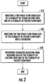
- the method includes directing a two phase flow from each of a plurality of steam ejectors 110 into one of a plurality of passive flow traps 118.
- the method includes directing the two phase flow from each of the plurality of passive flow traps 118 into a separator 125.
- the method includes preventing separator backflow from reaching each of the plurality of steam ejectors 110 with one of the plurality of passive flow traps 118.
- the above disclosed embodiments provide a system 100 that mitigates a possibility of reverse flow from the separator 125 to the plurality of steam ejectors 110.
- the system 100 may increase an operating efficiency associated with utilizing a multi-ejector configuration while minimizing a risk of reverse flow.
Landscapes
- Engineering & Computer Science (AREA)
- Physics & Mathematics (AREA)
- Mechanical Engineering (AREA)
- Thermal Sciences (AREA)
- General Engineering & Computer Science (AREA)
- Jet Pumps And Other Pumps (AREA)
Description
- The invention relates to refrigeration systems and more specifically to a refrigeration system that includes a steam ejector and a flow trap.
- Commercial refrigeration systems (CRSs) represent a significant part of a power load in super markets. Steam ejectors are convergent-divergent devices that provide a pressure lift without requiring power and thereby are used to increase CRS efficiency. In order to satisfy different load conditions, parallel multi-ejectors configurations (with a same or different sizes) may be installed in a CRS. However, when multiple ejectors operate at the same time, there may be risks of unstable operations, for example, reverse flow (RF), due to different operating characteristics and output capacities among the ejectors.
JP H10 89814 A - The present invention which is defined in claim 1 provides a refrigeration system comprising: a steam ejector with an ejector outlet; and a passive flow trap connected to the ejector outlet. The passive flow trap includes an inlet-side drop, a center bend, and an outlet-side rise, thereby defining a U shape, and the inlet-side drop is larger than the outlet-side rise.
- The system may include a separator connected to an outlet-side of the passive flow trap.
- Optionally, the passive flow trap is connected to a lower portion of the separator that is configured to store liquid refrigerant.
- Optionally, the system comprises one or more additional steam ejectors, each of which including one of one or more additional ejector outlets; and one or more additional passive flow traps, one of which connected to each of the one or more additional ejector outlets.
- Each of the one or more additional passive flow traps may include an inlet-side drop, a center bend, and an outlet-side rise, thereby defining a U shape.
- For at least two of the passive flow trap and one or more additional passive flow traps, the outlet-side rise may be the same.
- For each of the passive flow trap and one or more additional passive flow traps, the outlet-side rise may be the same.
- For each of the passive flow trap and one or more additional passive flow traps, the outlet-side rise may be different.
- Optionally, the system includes a separator connected to an outlet-side of each of the passive flow trap and one or more additional passive flow traps.
- The passive flow trap and one or more additional passive flow traps may be connected to a lower portion of the separator that is configured to store liquid refrigerant.
- The system may include an evaporator, wherein each of the steam ejector and one or more additional steam ejectors includes one of a plurality of ejector first-inlets, each of the plurality of ejector first-inlets is connected to the evaporator.
- The system may include a plurality of shut-off valves, wherein each of a plurality of shut off valves is connected between the evaporator and one of the plurality of ejector first-inlets.
- The separator may include a first outlet connected to an expansion device.
- Optionally, the system includes a gas cooler, wherein each of the steam ejector and one or more additional steam ejectors includes one of a plurality of ejector second-inlets, each of the plurality of ejector second-inlets is connected to the gas cooler.
- The system may include a compressor, wherein the separator includes a second outlet connected to the compressor.
- A second aspect of the invention provides a method of directing flow in a refrigerant system comprising: directing a two phase flow from each of a plurality of steam ejectors into one of a plurality of passive flow traps; directing the two phase flow from each of the plurality of passive flow traps into a separator; and preventing backflow from the separator from reaching each of the plurality of steam ejectors with one of the plurality of passive flow traps. Each of the plurality of passive flow traps includes an inlet-side drop, a center bend, and an outlet-side rise, thereby defining a U shape, and for at least one of the plurality of passive flow traps, the inlet-side drop is larger than the outlet-side rise.
- .
- The present invention is illustrated by way of example and not limited in the accompanying figures in which like reference numerals indicate similar elements.
-
FIG. 1 is a schematic illustration of a refrigerant system according to an embodiment of the present invention; and -
FIG. 2 is a flow diagram showing a process of directing flow in a refrigerant system according to an embodiment. - Turning to
FIG. 1 , the disclosed embodiments provide a configuration for a refrigeration system (system) 100 with a plurality ofsteam ejectors 110, wherein backflow from aseparator 125 may be minimized. The plurality ofsteam ejectors 110 are illustrated as including threeejectors 110a-110c each with one of a plurality of ejector outlets 115 so that threeoutlets 115a-115c are illustrated. Each of the ejector outlets 115 is connected to one of a plurality ofpassive flow traps 118 so that threepassive flow traps 118a-118c are illustrated. Though sets of three features are illustrated and disclosed herein, such as threesteam ejectors 110 andpassive flow traps 118, the disclosure is not intended to limit the scope of a number of features that may fall within the scope of the invention and appended claims. - Each of the
passive flow traps 118 includes an inlet-side drop (relative to gravity) 120, acenter bend 122 and an outlet-side rise (relative to gravity) 124 so as to define a U shape. Accordingly, three inlet-side drops 120a-120c, threecenter bends 122a-122c and three outlet-side rises 124a-124c are illustrated. Aseparator 125 is connected the outlet-side rise 124 of each of thepassive flow traps 118. More specifically, thepassive flow traps 118 are connected to alower portion 130 of theseparator 125 that normally contains accumulatedliquid refrigerant 135. - A height span of each of the outlet-side rises 124a-124c can be a same distance or a different distance for each of the plurality of
steam ejectors 110. There will typically be at least some liquid stored in one of thepassive flow traps 118 if outlet pressure of the respective one of thesteam ejectors 110 is lower than pressure at theseparator 125. Such fluid in thetraps 118 prevents backflow. That is, in such situation, thepassive flow traps 118 each functions as a pressure buffer to avoid reverse flow from theseparator 125. According to hydrostatic pressure theory, the static pressure provided by the U-shape could be estimated by p=ρgh, where ρ, g and h are density of liquid refrigerant, gravitational constant and height of outlet-side rise, respectively. As long as the pressure difference between ejector outlet and separator is lower than this value, the reverse flow may be avoided. - As further illustrated, the
system 100 includes an expansion device and anevaporator 140, illustrated schematically. Each of the plurality ofsteam ejectors 110 includes one of a plurality of ejector first-inlets 145 so that three of the ejector first-inlets 145a-145c are illustrated. Each of the ejector first-inlets 145 is connected to theevaporator 140. Further, each of a plurality of shut-offvalves 150 is connected between theevaporator 140 and one of the ejector first-inlets 145, so that three shut-offvalves 150a-150c are illustrated. - The system further includes a
gas cooler 155 illustrated schematically. Each of the plurality ofsteam ejectors 110 includes one of a plurality of ejector second-inlets 160 so that three of the ejector second-inlets 160a-160c are illustrated. Each of the ejector second-inlets 160 is connected to thegas cooler 155. Theseparator 125 includes afirst outlet 170 connected to the evaporator and asecond outlet 175 connected to acompressor 180 of thesystem 100. - Turning to
FIG. 2 , a method is shown in a flow chart of directing flow in thesystem 100. As illustrated inblock 510, the method includes directing a two phase flow from each of a plurality ofsteam ejectors 110 into one of a plurality ofpassive flow traps 118. As illustrated inblock 520, the method includes directing the two phase flow from each of the plurality ofpassive flow traps 118 into aseparator 125. As illustrated inblock 530, the method includes preventing separator backflow from reaching each of the plurality ofsteam ejectors 110 with one of the plurality ofpassive flow traps 118. - The above disclosed embodiments provide a
system 100 that mitigates a possibility of reverse flow from theseparator 125 to the plurality ofsteam ejectors 110. Thesystem 100 may increase an operating efficiency associated with utilizing a multi-ejector configuration while minimizing a risk of reverse flow. - The terminology used herein is for the purpose of describing particular embodiments only and is not intended to be limiting of the present invention. As used herein, the singular forms "a", "an" and "the" are intended to include the plural forms as well, unless the context clearly indicates otherwise. It will be further understood that the terms "comprises" and/or "comprising," when used in this specification, specify the presence of stated features, integers, steps, operations, elements, and/or components, but do not preclude the presence or addition of one or more other features, integers, steps, operations, element components, and/or groups thereof.
- Those of skill in the art will appreciate that various example embodiments are shown and described herein, each having certain features in the particular embodiments, but the present invention is not thus limited. While various embodiments of the present invention have been described, it is to be understood that aspects of the present invention may include only some of the described embodiments. Accordingly, the present invention is not to be seen as limited by the foregoing description, but is only limited by the scope of the appended claims.
Claims (15)
- A refrigeration system (100) comprising:a steam ejector (110) with an ejector outlet (115); anda passive flow trap (118) connected to the ejector outlet (115),wherein the passive flow trap (118) includes an inlet-side drop (120), a center bend (122), and an outlet-side rise (124), thereby defining a U shape, characterised in that the inlet-side drop (120) is larger than the outlet-side rise (124).
- The system of claim 1, comprising a separator (125) connected to an outlet-side of the passive flow trap (118).
- The system of claim 2, wherein the passive flow trap (118) is connected to a lower portion of the separator (125) that is configured to store liquid refrigerant (135).
- The system of claim 1, further comprising:one or more additional steam ejectors (110), each of which including one of one or more additional ejector outlets (115); andone or more additional passive flow traps (118), one of which connected to each of the one or more additional ejector outlets (115).
- The system of claim 4, wherein each of the one or more additional passive flow traps (118) includes an inlet-side drop (120), a center bend (122), and an outlet-side rise (124), thereby defining a U shape.
- The system of claim 5, wherein for at least two of the passive flow trap (118) and one or more additional passive flow traps (118), the outlet-side rise (124) is the same.
- The system of claim 5, wherein for each of the passive flow trap (118) and one or more additional passive flow traps (118), the outlet-side rise is the same (124).
- The system of claim 5, wherein for each of the passive flow trap (118) and one or more additional passive flow traps (118), the outlet-side rise (124) is different.
- The system of claim 5, comprising a separator (125) connected to an outlet-side of each of the passive flow trap (118) and one or more additional passive flow traps (118), optionally wherein the passive flow trap (118) and one or more additional passive flow traps (118) are connected to a lower portion of the separator (125) that is configured to store liquid refrigerant (135).
- The system of claim 9, including an evaporator (140), wherein each of the steam ejector (110) and one or more additional steam ejectors (110) includes one of a plurality of ejector first-inlets (145), each of the plurality of ejector first-inlets is connected to the evaporator (140).
- The system of claim 10, including a plurality of shut-off valves (150), wherein each of a plurality of shut off valves is connected between the evaporator (140) and one of the plurality of ejector first-inlets (145).
- The system of claim 11, wherein the separator (125) includes a first outlet (170) connected to an expansion device.
- The system of claim 12, including a gas cooler (155), wherein each of the steam ejector (110) and one or more additional steam ejectors (110) includes one of a plurality of ejector second-inlets (160), each of the plurality of ejector second-inlets is connected to the gas cooler (155).
- The system of claim 13, including a compressor (180), wherein the separator (125) includes a second outlet (175) connected to the compressor (180).
- A method of directing flow in a refrigerant system comprising:directing a two phase flow from each of a plurality of steam ejectors (110) into one of a plurality of passive flow traps (118);directing the two phase flow from each of the plurality of passive flow traps (118) into a separator (125); andpreventing backflow from the separator (125) from reaching each of the plurality of steam ejectors (110) with one of the plurality of passive flow traps (118),wherein each of the plurality of passive flow traps (118) includes an inlet-side drop (120), a center bend (122), and an outlet-side rise (124), thereby defining a U shape, and for at least one of the plurality of passive flow traps (118), the inlet-side drop (122) is larger than the outlet-side rise (124).
Applications Claiming Priority (2)
| Application Number | Priority Date | Filing Date | Title |
|---|---|---|---|
| US201962888824P | 2019-08-19 | 2019-08-19 | |
| PCT/US2020/044160 WO2021034469A1 (en) | 2019-08-19 | 2020-07-30 | Refrigeration system with a plurality of steam ejectors connected to a plurality of flow traps |
Publications (2)
| Publication Number | Publication Date |
|---|---|
| EP4018135A1 EP4018135A1 (en) | 2022-06-29 |
| EP4018135B1 true EP4018135B1 (en) | 2025-04-23 |
Family
ID=72145476
Family Applications (1)
| Application Number | Title | Priority Date | Filing Date |
|---|---|---|---|
| EP20758011.9A Active EP4018135B1 (en) | 2019-08-19 | 2020-07-30 | Refrigeration system with a plurality of steam ejectors connected to a plurality of flow traps |
Country Status (4)
| Country | Link |
|---|---|
| US (1) | US12013164B2 (en) |
| EP (1) | EP4018135B1 (en) |
| CN (1) | CN112714851B (en) |
| WO (1) | WO2021034469A1 (en) |
Families Citing this family (6)
| Publication number | Priority date | Publication date | Assignee | Title |
|---|---|---|---|---|
| US20250085033A1 (en) * | 2023-06-30 | 2025-03-13 | Carrier Corporation | System and method for detection and correction of reverse flow in an ejector refrigeration circui |
| US20250052465A1 (en) * | 2023-08-07 | 2025-02-13 | Carrier Corporation | System and method for controlling a plurality of ejectors in an ejector refrigeration circuit |
| US20250129978A1 (en) * | 2023-10-19 | 2025-04-24 | Carrier Corporation | System and method for map-interpolation based control of ejectors in an ejector refrigeration circuit |
| DE102024203739A1 (en) * | 2024-04-22 | 2025-10-23 | Volkswagen Aktiengesellschaft | Phase separator and motor vehicle |
| EP4745489A1 (en) * | 2024-11-14 | 2026-05-20 | Robert Bosch GmbH | JET PUMP UNIT AND REFRIGERANT CIRCUIT |
| WO2026104332A1 (en) * | 2024-11-14 | 2026-05-21 | Robert Bosch Gmbh | Jet pump unit and refrigerant circuit |
Family Cites Families (9)
| Publication number | Priority date | Publication date | Assignee | Title |
|---|---|---|---|---|
| US1836318A (en) | 1926-07-26 | 1931-12-15 | Norman H Gay | Refrigerating system |
| JP3209927B2 (en) * | 1996-09-18 | 2001-09-17 | リンナイ株式会社 | Absorption refrigeration equipment |
| JP4529727B2 (en) | 2005-02-23 | 2010-08-25 | 富士電機リテイルシステムズ株式会社 | Refrigerant circuit |
| US8628025B2 (en) | 2010-03-09 | 2014-01-14 | GM Global Technology Operations LLC | Vehicle waste heat recovery system and method of operation |
| US20130111944A1 (en) * | 2010-07-23 | 2013-05-09 | Carrier Corporation | High Efficiency Ejector Cycle |
| CN103282730B (en) * | 2011-01-04 | 2016-03-09 | 开利公司 | Ejector cycle |
| US9657969B2 (en) | 2013-12-30 | 2017-05-23 | Rolls-Royce Corporation | Multi-evaporator trans-critical cooling systems |
| CN106322807B (en) | 2015-07-03 | 2021-05-28 | 开利公司 | Ejector heat pump |
| CN205261972U (en) | 2015-11-13 | 2016-05-25 | 陕西盛迈石油有限公司 | Ejecting type pump -free circulation refrigerating system |
-
2020
- 2020-07-30 WO PCT/US2020/044160 patent/WO2021034469A1/en not_active Ceased
- 2020-07-30 CN CN202080003559.3A patent/CN112714851B/en active Active
- 2020-07-30 US US17/253,169 patent/US12013164B2/en active Active
- 2020-07-30 EP EP20758011.9A patent/EP4018135B1/en active Active
Also Published As
| Publication number | Publication date |
|---|---|
| EP4018135A1 (en) | 2022-06-29 |
| US12013164B2 (en) | 2024-06-18 |
| US20220299239A1 (en) | 2022-09-22 |
| WO2021034469A1 (en) | 2021-02-25 |
| CN112714851B (en) | 2024-09-20 |
| CN112714851A (en) | 2021-04-27 |
Similar Documents
| Publication | Publication Date | Title |
|---|---|---|
| US12013164B2 (en) | Refrigeration system with a plurality of steam ejectors connected to a plurality of flow traps | |
| CA2047551C (en) | Compact modular refrigerant coil apparatus and associated manufacturing methods | |
| JP6767196B2 (en) | Economizer | |
| EP3568650B1 (en) | Oil management for micro booster supermarket refrigeration system | |
| US9027363B2 (en) | Economizer having multiple liquid outlets and multiple float expansion valves | |
| US20050178149A1 (en) | Gas-liquid separator | |
| EP3699502B1 (en) | Air conditioner | |
| EP2886978B1 (en) | Distributor unit and evaporator having the same | |
| EP3312527B1 (en) | Refrigerant circuit and air conditioner | |
| CN106574812A (en) | Outdoor unit and refrigeration cycle apparatus | |
| EP4246075A2 (en) | Heat exchanger for heat pump applications | |
| JP5696084B2 (en) | Air conditioner | |
| JP2018004093A (en) | Accumulator of refrigeration cycle device | |
| US5228197A (en) | Refrigerant coil fabrication methods | |
| JP5757415B2 (en) | Refrigeration equipment such as air conditioners | |
| AU2024201902B2 (en) | Oil management system for multiple compressors | |
| EP3087331B1 (en) | Refrigerant riser for evaporator | |
| US20170227268A1 (en) | Lubricant separator for a heating, ventilation, and air conditioning system | |
| US11175078B2 (en) | Gas-liquid separator and air conditioner including the same | |
| JP2014109416A (en) | Air conditioner | |
| EP3936791A1 (en) | Heat exchanger and refrigeration cycle device | |
| KR102294499B1 (en) | Multistage compression type frozen apparatus | |
| JPS6397806A (en) | Drain discharge device for steam turbine | |
| US11448435B2 (en) | Evaporator and refrigeration system | |
| CN101002025A (en) | Dynamically controlled compressors |
Legal Events
| Date | Code | Title | Description |
|---|---|---|---|
| STAA | Information on the status of an ep patent application or granted ep patent |
Free format text: STATUS: UNKNOWN |
|
| STAA | Information on the status of an ep patent application or granted ep patent |
Free format text: STATUS: THE INTERNATIONAL PUBLICATION HAS BEEN MADE |
|
| PUAI | Public reference made under article 153(3) epc to a published international application that has entered the european phase |
Free format text: ORIGINAL CODE: 0009012 |
|
| STAA | Information on the status of an ep patent application or granted ep patent |
Free format text: STATUS: REQUEST FOR EXAMINATION WAS MADE |
|
| 17P | Request for examination filed |
Effective date: 20210110 |
|
| AK | Designated contracting states |
Kind code of ref document: A1 Designated state(s): AL AT BE BG CH CY CZ DE DK EE ES FI FR GB GR HR HU IE IS IT LI LT LU LV MC MK MT NL NO PL PT RO RS SE SI SK SM TR |
|
| DAV | Request for validation of the european patent (deleted) | ||
| DAX | Request for extension of the european patent (deleted) | ||
| GRAP | Despatch of communication of intention to grant a patent |
Free format text: ORIGINAL CODE: EPIDOSNIGR1 |
|
| STAA | Information on the status of an ep patent application or granted ep patent |
Free format text: STATUS: GRANT OF PATENT IS INTENDED |
|
| INTG | Intention to grant announced |
Effective date: 20241216 |
|
| GRAS | Grant fee paid |
Free format text: ORIGINAL CODE: EPIDOSNIGR3 |
|
| GRAA | (expected) grant |
Free format text: ORIGINAL CODE: 0009210 |
|
| STAA | Information on the status of an ep patent application or granted ep patent |
Free format text: STATUS: THE PATENT HAS BEEN GRANTED |
|
| AK | Designated contracting states |
Kind code of ref document: B1 Designated state(s): AL AT BE BG CH CY CZ DE DK EE ES FI FR GB GR HR HU IE IS IT LI LT LU LV MC MK MT NL NO PL PT RO RS SE SI SK SM TR |
|
| REG | Reference to a national code |
Ref country code: GB Ref legal event code: FG4D |
|
| REG | Reference to a national code |
Ref country code: CH Ref legal event code: EP |
|
| REG | Reference to a national code |
Ref country code: DE Ref legal event code: R096 Ref document number: 602020049985 Country of ref document: DE |
|
| REG | Reference to a national code |
Ref country code: NL Ref legal event code: FP Ref country code: IE Ref legal event code: FG4D |
|
| REG | Reference to a national code |
Ref country code: AT Ref legal event code: MK05 Ref document number: 1788096 Country of ref document: AT Kind code of ref document: T Effective date: 20250423 |
|
| PG25 | Lapsed in a contracting state [announced via postgrant information from national office to epo] |
Ref country code: FI Free format text: LAPSE BECAUSE OF FAILURE TO SUBMIT A TRANSLATION OF THE DESCRIPTION OR TO PAY THE FEE WITHIN THE PRESCRIBED TIME-LIMIT Effective date: 20250423 Ref country code: PT Free format text: LAPSE BECAUSE OF FAILURE TO SUBMIT A TRANSLATION OF THE DESCRIPTION OR TO PAY THE FEE WITHIN THE PRESCRIBED TIME-LIMIT Effective date: 20250825 Ref country code: ES Free format text: LAPSE BECAUSE OF FAILURE TO SUBMIT A TRANSLATION OF THE DESCRIPTION OR TO PAY THE FEE WITHIN THE PRESCRIBED TIME-LIMIT Effective date: 20250423 |
|
| PGFP | Annual fee paid to national office [announced via postgrant information from national office to epo] |
Ref country code: DE Payment date: 20250620 Year of fee payment: 6 |
|
| REG | Reference to a national code |
Ref country code: LT Ref legal event code: MG9D |
|
| PG25 | Lapsed in a contracting state [announced via postgrant information from national office to epo] |
Ref country code: NO Free format text: LAPSE BECAUSE OF FAILURE TO SUBMIT A TRANSLATION OF THE DESCRIPTION OR TO PAY THE FEE WITHIN THE PRESCRIBED TIME-LIMIT Effective date: 20250723 Ref country code: GR Free format text: LAPSE BECAUSE OF FAILURE TO SUBMIT A TRANSLATION OF THE DESCRIPTION OR TO PAY THE FEE WITHIN THE PRESCRIBED TIME-LIMIT Effective date: 20250724 |
|
| PG25 | Lapsed in a contracting state [announced via postgrant information from national office to epo] |
Ref country code: PL Free format text: LAPSE BECAUSE OF FAILURE TO SUBMIT A TRANSLATION OF THE DESCRIPTION OR TO PAY THE FEE WITHIN THE PRESCRIBED TIME-LIMIT Effective date: 20250423 |
|
| PG25 | Lapsed in a contracting state [announced via postgrant information from national office to epo] |
Ref country code: BG Free format text: LAPSE BECAUSE OF FAILURE TO SUBMIT A TRANSLATION OF THE DESCRIPTION OR TO PAY THE FEE WITHIN THE PRESCRIBED TIME-LIMIT Effective date: 20250423 |
|
| PG25 | Lapsed in a contracting state [announced via postgrant information from national office to epo] |
Ref country code: HR Free format text: LAPSE BECAUSE OF FAILURE TO SUBMIT A TRANSLATION OF THE DESCRIPTION OR TO PAY THE FEE WITHIN THE PRESCRIBED TIME-LIMIT Effective date: 20250423 |
|
| PG25 | Lapsed in a contracting state [announced via postgrant information from national office to epo] |
Ref country code: AT Free format text: LAPSE BECAUSE OF FAILURE TO SUBMIT A TRANSLATION OF THE DESCRIPTION OR TO PAY THE FEE WITHIN THE PRESCRIBED TIME-LIMIT Effective date: 20250423 |
|
| PG25 | Lapsed in a contracting state [announced via postgrant information from national office to epo] |
Ref country code: RS Free format text: LAPSE BECAUSE OF FAILURE TO SUBMIT A TRANSLATION OF THE DESCRIPTION OR TO PAY THE FEE WITHIN THE PRESCRIBED TIME-LIMIT Effective date: 20250723 |
|
| PG25 | Lapsed in a contracting state [announced via postgrant information from national office to epo] |
Ref country code: IS Free format text: LAPSE BECAUSE OF FAILURE TO SUBMIT A TRANSLATION OF THE DESCRIPTION OR TO PAY THE FEE WITHIN THE PRESCRIBED TIME-LIMIT Effective date: 20250823 |
|
| PG25 | Lapsed in a contracting state [announced via postgrant information from national office to epo] |
Ref country code: LV Free format text: LAPSE BECAUSE OF FAILURE TO SUBMIT A TRANSLATION OF THE DESCRIPTION OR TO PAY THE FEE WITHIN THE PRESCRIBED TIME-LIMIT Effective date: 20250423 |
|
| PG25 | Lapsed in a contracting state [announced via postgrant information from national office to epo] |
Ref country code: DK Free format text: LAPSE BECAUSE OF FAILURE TO SUBMIT A TRANSLATION OF THE DESCRIPTION OR TO PAY THE FEE WITHIN THE PRESCRIBED TIME-LIMIT Effective date: 20250423 Ref country code: SM Free format text: LAPSE BECAUSE OF FAILURE TO SUBMIT A TRANSLATION OF THE DESCRIPTION OR TO PAY THE FEE WITHIN THE PRESCRIBED TIME-LIMIT Effective date: 20250423 |
|
| PG25 | Lapsed in a contracting state [announced via postgrant information from national office to epo] |
Ref country code: CZ Free format text: LAPSE BECAUSE OF FAILURE TO SUBMIT A TRANSLATION OF THE DESCRIPTION OR TO PAY THE FEE WITHIN THE PRESCRIBED TIME-LIMIT Effective date: 20250423 |
|
| PG25 | Lapsed in a contracting state [announced via postgrant information from national office to epo] |
Ref country code: EE Free format text: LAPSE BECAUSE OF FAILURE TO SUBMIT A TRANSLATION OF THE DESCRIPTION OR TO PAY THE FEE WITHIN THE PRESCRIBED TIME-LIMIT Effective date: 20250423 |
|
| REG | Reference to a national code |
Ref country code: DE Ref legal event code: R097 Ref document number: 602020049985 Country of ref document: DE |
|
| PG25 | Lapsed in a contracting state [announced via postgrant information from national office to epo] |
Ref country code: RO Free format text: LAPSE BECAUSE OF FAILURE TO SUBMIT A TRANSLATION OF THE DESCRIPTION OR TO PAY THE FEE WITHIN THE PRESCRIBED TIME-LIMIT Effective date: 20250423 Ref country code: SK Free format text: LAPSE BECAUSE OF FAILURE TO SUBMIT A TRANSLATION OF THE DESCRIPTION OR TO PAY THE FEE WITHIN THE PRESCRIBED TIME-LIMIT Effective date: 20250423 |
|
| PG25 | Lapsed in a contracting state [announced via postgrant information from national office to epo] |
Ref country code: IT Free format text: LAPSE BECAUSE OF FAILURE TO SUBMIT A TRANSLATION OF THE DESCRIPTION OR TO PAY THE FEE WITHIN THE PRESCRIBED TIME-LIMIT Effective date: 20250423 |
|
| REG | Reference to a national code |
Ref country code: CH Ref legal event code: H13 Free format text: ST27 STATUS EVENT CODE: U-0-0-H10-H13 (AS PROVIDED BY THE NATIONAL OFFICE) Effective date: 20260224 |
|
| PLBE | No opposition filed within time limit |
Free format text: ORIGINAL CODE: 0009261 |
|
| STAA | Information on the status of an ep patent application or granted ep patent |
Free format text: STATUS: NO OPPOSITION FILED WITHIN TIME LIMIT |
|
| REG | Reference to a national code |
Ref country code: CH Ref legal event code: L10 Free format text: ST27 STATUS EVENT CODE: U-0-0-L10-L00 (AS PROVIDED BY THE NATIONAL OFFICE) Effective date: 20260304 |
|
| PG25 | Lapsed in a contracting state [announced via postgrant information from national office to epo] |
Ref country code: LU Free format text: LAPSE BECAUSE OF NON-PAYMENT OF DUE FEES Effective date: 20250730 |
|
| REG | Reference to a national code |
Ref country code: BE Ref legal event code: MM Effective date: 20250731 |
|
| 26N | No opposition filed |
Effective date: 20260126 |
|
| PG25 | Lapsed in a contracting state [announced via postgrant information from national office to epo] |
Ref country code: BE Free format text: LAPSE BECAUSE OF NON-PAYMENT OF DUE FEES Effective date: 20250731 |
|
| PG25 | Lapsed in a contracting state [announced via postgrant information from national office to epo] |
Ref country code: CH Free format text: LAPSE BECAUSE OF NON-PAYMENT OF DUE FEES Effective date: 20250731 |
|
| PG25 | Lapsed in a contracting state [announced via postgrant information from national office to epo] |
Ref country code: LT Free format text: LAPSE BECAUSE OF FAILURE TO SUBMIT A TRANSLATION OF THE DESCRIPTION OR TO PAY THE FEE WITHIN THE PRESCRIBED TIME-LIMIT Effective date: 20250423 |
|
| PGFP | Annual fee paid to national office [announced via postgrant information from national office to epo] |
Ref country code: GB Payment date: 20260618 Year of fee payment: 7 |
|
| PG25 | Lapsed in a contracting state [announced via postgrant information from national office to epo] |
Ref country code: IE Free format text: LAPSE BECAUSE OF NON-PAYMENT OF DUE FEES Effective date: 20250730 |
|
| PG25 | Lapsed in a contracting state [announced via postgrant information from national office to epo] |
Ref country code: MC Free format text: LAPSE BECAUSE OF FAILURE TO SUBMIT A TRANSLATION OF THE DESCRIPTION OR TO PAY THE FEE WITHIN THE PRESCRIBED TIME-LIMIT Effective date: 20250423 |
|
| PGFP | Annual fee paid to national office [announced via postgrant information from national office to epo] |
Ref country code: NL Payment date: 20260622 Year of fee payment: 7 |
|
| PGFP | Annual fee paid to national office [announced via postgrant information from national office to epo] |
Ref country code: FR Payment date: 20260619 Year of fee payment: 7 |
|
| PG25 | Lapsed in a contracting state [announced via postgrant information from national office to epo] |
Ref country code: CY Free format text: LAPSE BECAUSE OF FAILURE TO SUBMIT A TRANSLATION OF THE DESCRIPTION OR TO PAY THE FEE WITHIN THE PRESCRIBED TIME-LIMIT Effective date: 20250423 Ref country code: SE Free format text: LAPSE BECAUSE OF FAILURE TO SUBMIT A TRANSLATION OF THE DESCRIPTION OR TO PAY THE FEE WITHIN THE PRESCRIBED TIME-LIMIT Effective date: 20250423 |