EP4017426B1 - 3d printed prosthetic socket for residual limb - Google Patents
3d printed prosthetic socket for residual limb Download PDFInfo
- Publication number
- EP4017426B1 EP4017426B1 EP20789819.8A EP20789819A EP4017426B1 EP 4017426 B1 EP4017426 B1 EP 4017426B1 EP 20789819 A EP20789819 A EP 20789819A EP 4017426 B1 EP4017426 B1 EP 4017426B1
- Authority
- EP
- European Patent Office
- Prior art keywords
- housing
- prosthetic socket
- printed
- socket
- residual limb
- Prior art date
- Legal status (The legal status is an assumption and is not a legal conclusion. Google has not performed a legal analysis and makes no representation as to the accuracy of the status listed.)
- Active
Links
Images



Classifications
-
- A—HUMAN NECESSITIES
- A61—MEDICAL OR VETERINARY SCIENCE; HYGIENE
- A61F—FILTERS IMPLANTABLE INTO BLOOD VESSELS; PROSTHESES; DEVICES PROVIDING PATENCY TO, OR PREVENTING COLLAPSING OF, TUBULAR STRUCTURES OF THE BODY, e.g. STENTS; ORTHOPAEDIC, NURSING OR CONTRACEPTIVE DEVICES; FOMENTATION; TREATMENT OR PROTECTION OF EYES OR EARS; BANDAGES, DRESSINGS OR ABSORBENT PADS; FIRST-AID KITS
- A61F2/00—Filters implantable into blood vessels; Prostheses, i.e. artificial substitutes or replacements for parts of the body; Appliances for connecting them with the body; Devices providing patency to, or preventing collapsing of, tubular structures of the body, e.g. stents
- A61F2/50—Prostheses not implantable in the body
- A61F2/78—Means for protecting prostheses or for attaching them to the body, e.g. bandages, harnesses, straps, or stockings for the limb stump
- A61F2/80—Sockets, e.g. of suction type
-
- A—HUMAN NECESSITIES
- A61—MEDICAL OR VETERINARY SCIENCE; HYGIENE
- A61F—FILTERS IMPLANTABLE INTO BLOOD VESSELS; PROSTHESES; DEVICES PROVIDING PATENCY TO, OR PREVENTING COLLAPSING OF, TUBULAR STRUCTURES OF THE BODY, e.g. STENTS; ORTHOPAEDIC, NURSING OR CONTRACEPTIVE DEVICES; FOMENTATION; TREATMENT OR PROTECTION OF EYES OR EARS; BANDAGES, DRESSINGS OR ABSORBENT PADS; FIRST-AID KITS
- A61F2/00—Filters implantable into blood vessels; Prostheses, i.e. artificial substitutes or replacements for parts of the body; Appliances for connecting them with the body; Devices providing patency to, or preventing collapsing of, tubular structures of the body, e.g. stents
- A61F2/50—Prostheses not implantable in the body
-
- A—HUMAN NECESSITIES
- A61—MEDICAL OR VETERINARY SCIENCE; HYGIENE
- A61F—FILTERS IMPLANTABLE INTO BLOOD VESSELS; PROSTHESES; DEVICES PROVIDING PATENCY TO, OR PREVENTING COLLAPSING OF, TUBULAR STRUCTURES OF THE BODY, e.g. STENTS; ORTHOPAEDIC, NURSING OR CONTRACEPTIVE DEVICES; FOMENTATION; TREATMENT OR PROTECTION OF EYES OR EARS; BANDAGES, DRESSINGS OR ABSORBENT PADS; FIRST-AID KITS
- A61F2/00—Filters implantable into blood vessels; Prostheses, i.e. artificial substitutes or replacements for parts of the body; Appliances for connecting them with the body; Devices providing patency to, or preventing collapsing of, tubular structures of the body, e.g. stents
- A61F2/50—Prostheses not implantable in the body
- A61F2/5044—Designing or manufacturing processes
- A61F2/5046—Designing or manufacturing processes for designing or making customized prostheses, e.g. using templates, finite-element analysis or CAD-CAM techniques
-
- A—HUMAN NECESSITIES
- A61—MEDICAL OR VETERINARY SCIENCE; HYGIENE
- A61F—FILTERS IMPLANTABLE INTO BLOOD VESSELS; PROSTHESES; DEVICES PROVIDING PATENCY TO, OR PREVENTING COLLAPSING OF, TUBULAR STRUCTURES OF THE BODY, e.g. STENTS; ORTHOPAEDIC, NURSING OR CONTRACEPTIVE DEVICES; FOMENTATION; TREATMENT OR PROTECTION OF EYES OR EARS; BANDAGES, DRESSINGS OR ABSORBENT PADS; FIRST-AID KITS
- A61F2/00—Filters implantable into blood vessels; Prostheses, i.e. artificial substitutes or replacements for parts of the body; Appliances for connecting them with the body; Devices providing patency to, or preventing collapsing of, tubular structures of the body, e.g. stents
- A61F2/50—Prostheses not implantable in the body
- A61F2/78—Means for protecting prostheses or for attaching them to the body, e.g. bandages, harnesses, straps, or stockings for the limb stump
- A61F2/7812—Interface cushioning members placed between the limb stump and the socket, e.g. bandages or stockings for the limb stump
-
- B—PERFORMING OPERATIONS; TRANSPORTING
- B33—ADDITIVE MANUFACTURING TECHNOLOGY
- B33Y—ADDITIVE MANUFACTURING, i.e. MANUFACTURING OF THREE-DIMENSIONAL [3D] OBJECTS BY ADDITIVE DEPOSITION, ADDITIVE AGGLOMERATION OR ADDITIVE LAYERING, e.g. BY 3D PRINTING, STEREOLITHOGRAPHY OR SELECTIVE LASER SINTERING
- B33Y80/00—Products made by additive manufacturing
-
- A—HUMAN NECESSITIES
- A61—MEDICAL OR VETERINARY SCIENCE; HYGIENE
- A61F—FILTERS IMPLANTABLE INTO BLOOD VESSELS; PROSTHESES; DEVICES PROVIDING PATENCY TO, OR PREVENTING COLLAPSING OF, TUBULAR STRUCTURES OF THE BODY, e.g. STENTS; ORTHOPAEDIC, NURSING OR CONTRACEPTIVE DEVICES; FOMENTATION; TREATMENT OR PROTECTION OF EYES OR EARS; BANDAGES, DRESSINGS OR ABSORBENT PADS; FIRST-AID KITS
- A61F2/00—Filters implantable into blood vessels; Prostheses, i.e. artificial substitutes or replacements for parts of the body; Appliances for connecting them with the body; Devices providing patency to, or preventing collapsing of, tubular structures of the body, e.g. stents
- A61F2/50—Prostheses not implantable in the body
- A61F2/5044—Designing or manufacturing processes
- A61F2/5046—Designing or manufacturing processes for designing or making customized prostheses, e.g. using templates, finite-element analysis or CAD-CAM techniques
- A61F2002/5047—Designing or manufacturing processes for designing or making customized prostheses, e.g. using templates, finite-element analysis or CAD-CAM techniques using mathematical models
- A61F2002/5049—Computer aided shaping, e.g. rapid prototyping
-
- A—HUMAN NECESSITIES
- A61—MEDICAL OR VETERINARY SCIENCE; HYGIENE
- A61F—FILTERS IMPLANTABLE INTO BLOOD VESSELS; PROSTHESES; DEVICES PROVIDING PATENCY TO, OR PREVENTING COLLAPSING OF, TUBULAR STRUCTURES OF THE BODY, e.g. STENTS; ORTHOPAEDIC, NURSING OR CONTRACEPTIVE DEVICES; FOMENTATION; TREATMENT OR PROTECTION OF EYES OR EARS; BANDAGES, DRESSINGS OR ABSORBENT PADS; FIRST-AID KITS
- A61F2/00—Filters implantable into blood vessels; Prostheses, i.e. artificial substitutes or replacements for parts of the body; Appliances for connecting them with the body; Devices providing patency to, or preventing collapsing of, tubular structures of the body, e.g. stents
- A61F2/50—Prostheses not implantable in the body
- A61F2/5044—Designing or manufacturing processes
- A61F2/5046—Designing or manufacturing processes for designing or making customized prostheses, e.g. using templates, finite-element analysis or CAD-CAM techniques
- A61F2002/505—Designing or manufacturing processes for designing or making customized prostheses, e.g. using templates, finite-element analysis or CAD-CAM techniques using CAD-CAM techniques or NC-techniques
-
- A—HUMAN NECESSITIES
- A61—MEDICAL OR VETERINARY SCIENCE; HYGIENE
- A61F—FILTERS IMPLANTABLE INTO BLOOD VESSELS; PROSTHESES; DEVICES PROVIDING PATENCY TO, OR PREVENTING COLLAPSING OF, TUBULAR STRUCTURES OF THE BODY, e.g. STENTS; ORTHOPAEDIC, NURSING OR CONTRACEPTIVE DEVICES; FOMENTATION; TREATMENT OR PROTECTION OF EYES OR EARS; BANDAGES, DRESSINGS OR ABSORBENT PADS; FIRST-AID KITS
- A61F2/00—Filters implantable into blood vessels; Prostheses, i.e. artificial substitutes or replacements for parts of the body; Appliances for connecting them with the body; Devices providing patency to, or preventing collapsing of, tubular structures of the body, e.g. stents
- A61F2/50—Prostheses not implantable in the body
- A61F2/60—Artificial legs or feet or parts thereof
- A61F2/66—Feet; Ankle joints
- A61F2002/6614—Feet
-
- A—HUMAN NECESSITIES
- A61—MEDICAL OR VETERINARY SCIENCE; HYGIENE
- A61F—FILTERS IMPLANTABLE INTO BLOOD VESSELS; PROSTHESES; DEVICES PROVIDING PATENCY TO, OR PREVENTING COLLAPSING OF, TUBULAR STRUCTURES OF THE BODY, e.g. STENTS; ORTHOPAEDIC, NURSING OR CONTRACEPTIVE DEVICES; FOMENTATION; TREATMENT OR PROTECTION OF EYES OR EARS; BANDAGES, DRESSINGS OR ABSORBENT PADS; FIRST-AID KITS
- A61F2/00—Filters implantable into blood vessels; Prostheses, i.e. artificial substitutes or replacements for parts of the body; Appliances for connecting them with the body; Devices providing patency to, or preventing collapsing of, tubular structures of the body, e.g. stents
- A61F2/50—Prostheses not implantable in the body
- A61F2/78—Means for protecting prostheses or for attaching them to the body, e.g. bandages, harnesses, straps, or stockings for the limb stump
- A61F2/7812—Interface cushioning members placed between the limb stump and the socket, e.g. bandages or stockings for the limb stump
- A61F2002/7837—Sleeves for attaching or protecting, i.e. open ended hoses
Definitions
- the invention relates to a 3D printed prosthetic socket for a residual limb as defined in the appended claims.
- High-quality and well-fitting prosthetic sockets are the basis for a comfortable life of a patient with a residual limb. Due to the individual parameters of each residual limb, it is necessary to make prosthetic sockets always tailored for the specific patient.
- the function of the prosthetic socket is both load-bearing, wherein weight is transferred from the residual limb to the prosthesis itself, and fixating, wherein it is necessary to ensure sufficient adhesion of the socket to the limb, but at the same time the socket needs to be comfortable for the patient.
- Prosthetic sockets are made with respect to the condition of the residual limb, the physical activity of the patient and their weight. Since these parameters may change at shorter or longer intervals during the patient's life, it is desirable that the manufacture of the prosthetic socket be as simple as possible and thus less expensive.
- the first step is to create a model of the residual limb, either manually in form of a casting and a physical model of the residual limb, or a digital CAD/CAM model, from which, in the second step, an individual prosthetic socket is created, most often by lamination or thermoplastic shaping.
- a disadvantage of these solutions is the time-consuming design and manufacture and the limitation of the design embodiment due to the technology used.
- the lightening of a specific portion of the residual limb is solved by inserting soft, for example silicone, pellets to the affected regions.
- soft, for example silicone for example, silicone
- the lightening of specific portions of a residual limb is discussed for greater patient comfort when wearing a prosthesis by inserting soft thinned flexible regions of a residual limb sleeve.
- a 3D printed prosthetic socket according to the present invention that comprises a second housing located outside of a first housing connected to the first housing in the proximal and distal region of the socket, wherein in this manner, an air gap is created between the housings, and the distal end adapted for linking an interconnecting adapter of the socket, the first housing and the second housing are made of single 3D printed part, wherein the first housing comprises an elastic region comprising set of shaped openings, and the first housing is connected with the second housing through a reinforcing structure composed of ribs. Ribs provide additional strength to the prosthetic socket.
- shaped openings are adapted to reduce the rigidity of the elastic region and provide it with directional expansibility, wherein the elastic region has a negative Poisson's number value.
- the second housing includes at least one opening.
- the 3D printed prosthetic socket according to the present invention comprises a lightened structure in the distal region designed based on at least one parameter from a set including at least weight of the patient, degree of their activity, length of the residual limb, geometry thereof, size of the prosthetic foot, type of the prosthetic foot, and total length of the prosthesis. Since the distal end comprises a significant portion of the volume of the socket, by optimizing the lightened structure, the weight of the entire socket is reduced and thereby the comfort of the patient with the residual limb is increased and material is saved.
- the 3D printed prosthetic socket according to the present invention is adapted for connection to the cover of the prosthesis that comprises linking elements from a set of a pin, opening, spring, groove, helix, clamp joint, thread, screw, and rivet.
- the 3D printed prosthetic socket is made of one type of material.
- the 3D printed prosthetic socket according to this invention may be made from two or more types of materials, wherein in this manner, the rigidity of individual regions of the first housing of the prosthetic socket may be adjusted.
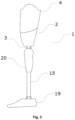
- the prosthetic socket 1 is, as shown in fig. 1 and fig. 2 , made of a solid material using the 3D printing technology, thereby creating a continuous and one-part shell with a cavity for the residual limb.
- the elastic modulus of the material used reaches 1,000 to 4,000 MPa at room temperature.
- the prosthetic socket 1 may be made by simultaneous one-part printing of several types of materials, wherein the materials may pass continuously or in leaps.
- the elastic modulus of the first material is 1,000 to 4,000 MPa at room temperature and the elastic modulus of another material is 3 to 200 MPa at room temperature.
- the first exemplary embodiment that is shown in fig. 1 and in fig.
- the prosthetic socket 1 comprises a distal end 2 adapted for linking the modular parts 15 of the lower limb prosthesis and a proximal end 4 with an opening for inserting the limb, between which the central portion of the prosthetic socket 1 is located.
- the distal end 2 is adapted for linking the prosthetic knee joint 20 .
- the central portion is made as containing two housings, wherein in a preferred embodiment, the central portion comprises the first housing 5 and the second housing 6 , between which a free space enclosed by these housings is located.
- the minimum thickness of the first housing 5 is 1 mm
- the minimum thickness of the second housing 6 is 1 mm
- the minimum distance between the first housing 5 and the second housing 6 is 1 mm.
- the prosthetic sockets 1 according to the present invention are made on a 3D printer using one of the 3D printing methods: SLA, SLS, FDM, MJF, DLP, 3DP, PJF, CLIP.
- One or more materials of which the prosthetic socket 1 is made belongs to the set of PA, ABS, PLA, PE, PP, CPP, HPP, TPU, TPE, photopolymers, and other materials suitable for the above-mentioned 3D printing methods.
- the chosen material may also be reinforced using fibers of glass, carbon, carbon nanofibers, or any other suitable fibers.
- the prosthetic socket 1 comprises an inner wall 7 that is in contact with the limb and has a load-bearing and a lightening function, and a rigid wall 8 that has a load-bearing and aesthetic function and, furthermore, is a representation of the outer shape of the socket of the prosthesis and simultaneously is adapted for shape alignment of the prosthesis with regard to the offset of the limb relative to the axis of the prosthesis.
- the central longitudinal axis of the inner space of the prosthetic socket 1 corresponds to the axis of the limb, and the central longitudinal axis of the outer surface follows the axis of the prosthesis.
- the relative position of the axis of the inner space and the axis of the outer space is different in most patients, wherein the central longitudinal axis of the inner space and the central axis of the outer space form an angle from the set of 0° to 90°, but most often 0° to 45°.
- the axes are identical and the solution according to this invention may be applied to these cases as well.
- the prosthetic socket 1 is adapted for transferring the load from the limb to the axis of the prosthesis connecting the prosthetic socket 1 to the prosthetic foot 19 . Due to the anatomy of the structure of the limb, it is necessary to lighten some of its regions, i.e. allow their shape and volume expansibility and provide space for possible swelling and prevent unwanted soft tissue bruising. This is achieved by including at least one elastic region 10 in the structure of the prosthetic socket 1 that achieves a maximum of 85% of the rigidity of the rigid region 9 at room temperature. In a preferred embodiment, the rigidity of the elastic region 10 is in the range of 5% to 85% o f the rigidity of the rigid region 9 at room temperature.
- the prosthetic socket 1 comprises two elastic regions 10 , in the posterolateral and posteromedial region.
- the elastic region 10 of the socket may be located in the posterior region, anterior region, medial region, or lateral region.
- the central portion comprises, arbitrarily according to the individual proportions of the patient, the residual limb, or the structure type of the prosthetic socket 1 , the elastic regions 10 .
- the prosthetic socket 1 in which the prosthetic socket 1 is made as containing two housings, only the first housing 5 comprises the elastic region 10 .
- the second housing 6 is hermetically sealed and its rigidity reaches at least 90% of the rigidity of the material used at room temperature. In an exemplary embodiment shown in fig.
- the second housing 6 comprises at least one opening 13 of the second housing that is of any shape, wherein the opening 13 of the second housing is adapted for moisture removal, aeration of the prosthetic socket 1 to the limb, removal of excess material during manufacture, reducing the weight of the second housing 6 , or it has an aesthetic function, or it is adapted for placement of a vacuum valve, lock, or another fastening mechanism, or is adapted for any combination of the functions listed.
- the elastic region 10 comprises a set of shaped openings 14 .
- An exemplary embodiment of the shaped openings 14 is shown in fig. 3 , wherein the shaped openings 14 may also be mutually interconnected and thus form more complex shapes. The openings may also have additional other various shapes for a defined purpose.
- the shaped openings 14 reduce the rigidity of the elastic region 10 and provide it with directional expansibility.
- the elastic region 10 is simultaneously expansible in multiple directions, i.e. it has a negative Poisson's number value.
- all shaped openings 14 of the set have the same shape and their size and distance change continuously, wherein their sizes increase towards the centre of the elastic region 10 .
- elastic elements 12 are located in the recess in the inner wall 7, which, depending on the shape, size, and inner structure, spring under load.
- the required lower rigidity of the prosthetic socket 1 and a lower load on the limb are achieved in the location of the elastic elements 12 .
- the rigidity of the regions 9 , 10 is determined by the specific shape, distance, and size of the shaped openings 14 located in the given region.
- the shaped openings 14 are smaller, they have a shape that ensures a greater rigidity of the rigid region 9 , and/or they are spaced from each other, or the shaped openings 14 are not located in the rigid regions 9 at all.
- thicker 3D printed structures are achieved that fill the space between the shaped openings 14 , while ensuring a higher rigidity of the rigid region 9 .
- thicker 3D printed structures are meant structures with a larger cross-section at the location between the shaped openings 14 and with a severalfold higher volume representation in proportion to the volume representation of the shaped openings 14 .
- the shaped openings 14 are bigger, they have a shape that ensures a lower rigidity of the elastic region 10 , and/or they are located in proximity to each other.
- thinner 3D printed structures are achieved that fill the space between the shaped openings 14 , while ensuring a lower rigidity of the elastic region 10 .
- thinner 3D printed structures are meant structures with a smaller cross-section at the location between the shaped openings 14 and with a severalfold lower volume representation in proportion to the volume representation of the shaped openings 14 , wherein they supply the required elasticity to the elastic region 10 if the limb in the prosthetic socket 1 exerts force on it.
- the transfer of the load at the distal end 2 of the socket of the prosthesis 1 is implemented using a lightened structure 11 shown in fig. 3 . It is designed using a finite element method by calculating the optimal material distribution with respect to the prosthesis geometry and the total transferred load. This load is based on the individual parameters of each patient, wherein the individual parameters are from a set comprising at least the patient's weight, physical activity, length of the limb, limb geometry, size of the prosthetic foot 19 , type of the prosthetic foot 19 , and the total length of the prosthesis that comprises the prosthetic socket 1 , a linking adapter 3 , modular parts 15 of the prosthesis, and the prosthetic foot 19 , wherein in another exemplary embodiment, it also comprises the cover 17 of the prosthesis.
- the prosthesis also includes the knee joint 20.
- the embodiment of the lightened structure 11 itself is designed also with regard to the need of removal of unnecessary material after the 3D printing, therefore, it does not comprise any enclosed space from which unused printing material could not be removed after manufacture.
- the distal end 2 of the prosthetic socket 1 is adapted for linking the linking adapter 3 , wherein the linking adapter 3 is further connected to the modular parts 15 of the prosthesis which are further connected to the prosthetic foot 19 .
- the linking adapter 3 is firmly connected to the prosthetic socket 1 , wherein the modular parts 15 of the prosthesis are detachably linked to the linking adapter 3 .
- the linking adapter 3 may be linked to the 3D printed prosthetic socket 1 using, for example, screws, snap-in mechanism, or thread, where the 3D printed prosthetic socket 1 comprises an outer thread and the linking adapter 3 comprises an inner thread, or the 3D printed prosthetic socket 1 comprises an inner thread and the linking adapter 3 comprises an outer thread.
- the prosthetic socket 1 is linked to the other portions of the prosthesis using a screw connection, wherein in this exemplary embodiment, the distal end 2 contains at least one opening for the thread.
- other structural joints may be used, such as, for example, nails, threaded inserts, pins, screws, lamellae, connecting fittings, or also gluing.
- the prosthetic socket 1 comprises the distal end 2 and the proximal end 4 , between which a central portion is located comprising the first housing 5 and the second housing 6 .
- a reinforcing structure composed of ribs 16 is located, as is shown in fig. 6 .
- the prosthetic socket 1 comprises a linking element 18 for linking the cover 17 of the prosthesis.
- the cover 17 of the prosthesis is continuous and one-part and is made of a solid or elastic material using the 3D printing technology.
- the function of the cover 17 of the prosthesis is aesthetic, wherein it covers the modular parts 15 of the prosthesis, in another exemplary embodiment, it also covers the knee joint 20 .
- the cover 17 of the prosthesis comprises, from the inner side of the edge for linking to the prosthetic socket 1 , at least one element adapted for connecting to the linking element 18 , wherein it is an opening, groove, or any other element corresponding, in terms of its shape, to the outer surface of the linking element 18 .
- the linking element 18 is a pin of approximately cylindrical shape, perpendicular to the inner wall 7 of the cover 17 of the prosthesis.
- the linking element 18 is embodied as a spring, clamp, at least 1 mm high edge, perpendicular to the inner wall 7 of the cover 17 of the prosthesis, diminishingly tapered edge of the cover 17 of the prosthesis, or as any other suitable dismountable joint.
- the prosthetic socket 1 comprises a recess corresponding to the size and thickness of the edge of the wall of the cover 17 of the prosthesis, wherein their connection creates a seamless joint that does not create any overlap between the socket 1 and the cover 17 of the prosthesis.
- the manufacture of the 3D printed prosthetic socket 1 according to the present invention is implemented using a system of a communicatively interconnected 3D scanner, computer device, and 3D printer, and it comprises a step of obtaining the digital image of the residual limb, step of adjusting the area of the digital image of the residual limb, and a design of the shell of the prosthetic socket 1 , and a step of manufacturing the prosthetic socket 1 on a 3D printer.
Landscapes
- Health & Medical Sciences (AREA)
- Engineering & Computer Science (AREA)
- Life Sciences & Earth Sciences (AREA)
- Animal Behavior & Ethology (AREA)
- Oral & Maxillofacial Surgery (AREA)
- Biomedical Technology (AREA)
- Heart & Thoracic Surgery (AREA)
- Vascular Medicine (AREA)
- Cardiology (AREA)
- Transplantation (AREA)
- General Health & Medical Sciences (AREA)
- Public Health (AREA)
- Veterinary Medicine (AREA)
- Manufacturing & Machinery (AREA)
- Chemical & Material Sciences (AREA)
- Materials Engineering (AREA)
- Prostheses (AREA)
Description
- The invention relates to a 3D printed prosthetic socket for a residual limb as defined in the appended claims.
- High-quality and well-fitting prosthetic sockets are the basis for a comfortable life of a patient with a residual limb. Due to the individual parameters of each residual limb, it is necessary to make prosthetic sockets always tailored for the specific patient. The function of the prosthetic socket is both load-bearing, wherein weight is transferred from the residual limb to the prosthesis itself, and fixating, wherein it is necessary to ensure sufficient adhesion of the socket to the limb, but at the same time the socket needs to be comfortable for the patient. Prosthetic sockets are made with respect to the condition of the residual limb, the physical activity of the patient and their weight. Since these parameters may change at shorter or longer intervals during the patient's life, it is desirable that the manufacture of the prosthetic socket be as simple as possible and thus less expensive.
- Most prior art prosthetic sockets are manufactured in two steps. The first step is to create a model of the residual limb, either manually in form of a casting and a physical model of the residual limb, or a digital CAD/CAM model, from which, in the second step, an individual prosthetic socket is created, most often by lamination or thermoplastic shaping. A disadvantage of these solutions is the time-consuming design and manufacture and the limitation of the design embodiment due to the technology used.
- Recently, efforts have been made to create 3D printed prosthetic sockets tailored for the patient based on a residual limb scan, a residual limb physical model scan, or residual limb measurements. According to the current state of the art, the digital model of the residual limb is modified in a computer, and on basis thereof, a CAD model of the socket is created, which is then printed on a 3D printer.
- The problem of this solution is, on the one hand, the requirement for sufficient strength of the socket, and, on the other hand, the requirement to ensure comfort for the residual limb for all-day wear. Thus, if the socket is to be strong enough to meet the strength standards imposed on sockets, such a socket is uncomfortable for the patient in case of volume changes of the limb.
- In the current state of the art, this problem is solved, for example, in patent document
US20170246013 , in which the prosthetic socket consists of an inner and outer surface, between which there are structural elastic elements allowing to reduce the pressure of the socket material on the residual limb. A disadvantage of this solution is the absence of adaptation of the flexibility of the socket to the specific residual limb, since each portion of the residual limb includes soft tissues and bone structures differently deforming over time. - In the current state of the art, the lightening of a specific portion of the residual limb is solved by inserting soft, for example silicone, pellets to the affected regions. For example, in the patent document
US20160228266 , the lightening of specific portions of a residual limb is discussed for greater patient comfort when wearing a prosthesis by inserting soft thinned flexible regions of a residual limb sleeve. - In the current state of the art, there is no outer supporting prosthetic socket that would solve the problem of softening a particular region in contact with the residual limb in 3D printed outer supporting prosthetic sockets and that would at the same time meet the requirements for strength, rigidity, and load-bearing capacity.
- The above shortcomings are, to a certain extent, overcome by a 3D printed prosthetic socket according to the present invention that comprises a second housing located outside of a first housing connected to the first housing in the proximal and distal region of the socket, wherein in this manner, an air gap is created between the housings, and the distal end adapted for linking an interconnecting adapter of the socket, the first housing and the second housing are made of single 3D printed part, wherein the first housing comprises an elastic region comprising set of shaped openings, and the first housing is connected with the second housing through a reinforcing structure composed of ribs. Ribs provide additional strength to the prosthetic socket.
- In preferred embodiment, shaped openings are adapted to reduce the rigidity of the elastic region and provide it with directional expansibility, wherein the elastic region has a negative Poisson's number value.
- To remove supporting or unused printing material during the manufacturing process the second housing includes at least one opening.
- The 3D printed prosthetic socket according to the present invention comprises a lightened structure in the distal region designed based on at least one parameter from a set including at least weight of the patient, degree of their activity, length of the residual limb, geometry thereof, size of the prosthetic foot, type of the prosthetic foot, and total length of the prosthesis. Since the distal end comprises a significant portion of the volume of the socket, by optimizing the lightened structure, the weight of the entire socket is reduced and thereby the comfort of the patient with the residual limb is increased and material is saved.
- The 3D printed prosthetic socket according to the present invention is adapted for connection to the cover of the prosthesis that comprises linking elements from a set of a pin, opening, spring, groove, helix, clamp joint, thread, screw, and rivet.
- In another preferred embodiment, the 3D printed prosthetic socket is made of one type of material. Alternatively, the 3D printed prosthetic socket according to this invention may be made from two or more types of materials, wherein in this manner, the rigidity of individual regions of the first housing of the prosthetic socket may be adjusted.
- A summary of the invention is further clarified using example embodiments thereof, which are described with reference to the accompanying drawings, in which:
-
fig. 1 shows a transtibial prosthesis comprising a 3D printed prosthetic socket and adjoining prosthetic parts, -
fig. 2 shows a transfemoral prosthesis comprising a 3D printed prosthetic socket and adjoining prosthetic parts, -
fig. 3 shows a cross-sectional view of the 3D printed prosthetic socket with the first housing comprising openings in the elastic region, and a lightened distal end structure, -
fig. 4 shows a detail of the arrangement of the second housing to the first housing of the 3D printed prosthetic socket, -
fig. 5 shows the 3D printed prosthetic socket with two housings and openings of the second housing, -
fig. 6 shows an example of the location of the ribs between the first and the second housing of the 3D printed prosthetic housing, -
fig. 7 shows a detail of the link of the cover of the prosthesis to the 3D printed prosthetic socket, -
fig. 8 shows an implementation of the elastic area by means of elastic elements in a recess in the inner wall of the 3D printed prosthetic socket. - Said embodiments show exemplary variants of the embodiments of the invention, which, however, have no limiting effect on the scope of protection.
- The
prosthetic socket 1 according to the present invention is, as shown infig. 1 andfig. 2 , made of a solid material using the 3D printing technology, thereby creating a continuous and one-part shell with a cavity for the residual limb. In a preferred embodiment, the elastic modulus of the material used reaches 1,000 to 4,000 MPa at room temperature. Alternatively, theprosthetic socket 1 may be made by simultaneous one-part printing of several types of materials, wherein the materials may pass continuously or in leaps. In this exemplary embodiment, the elastic modulus of the first material is 1,000 to 4,000 MPa at room temperature and the elastic modulus of another material is 3 to 200 MPa at room temperature. The first exemplary embodiment that is shown infig. 1 and infig. 2 , theprosthetic socket 1 comprises adistal end 2 adapted for linking themodular parts 15 of the lower limb prosthesis and aproximal end 4 with an opening for inserting the limb, between which the central portion of theprosthetic socket 1 is located. In another exemplary embodiment, thedistal end 2 is adapted for linking theprosthetic knee joint 20. In an exemplary embodiment that is shown infig. 4 , the central portion is made as containing two housings, wherein in a preferred embodiment, the central portion comprises thefirst housing 5 and thesecond housing 6, between which a free space enclosed by these housings is located. The minimum thickness of thefirst housing 5 is 1 mm, the minimum thickness of thesecond housing 6 is 1 mm, and the minimum distance between thefirst housing 5 and thesecond housing 6 is 1 mm. Theprosthetic sockets 1 according to the present invention are made on a 3D printer using one of the 3D printing methods: SLA, SLS, FDM, MJF, DLP, 3DP, PJF, CLIP. One or more materials of which theprosthetic socket 1 is made belongs to the set of PA, ABS, PLA, PE, PP, CPP, HPP, TPU, TPE, photopolymers, and other materials suitable for the above-mentioned 3D printing methods. The chosen material may also be reinforced using fibers of glass, carbon, carbon nanofibers, or any other suitable fibers. - Regardless of the embodiment of the central portion, the
prosthetic socket 1 comprises aninner wall 7 that is in contact with the limb and has a load-bearing and a lightening function, and arigid wall 8 that has a load-bearing and aesthetic function and, furthermore, is a representation of the outer shape of the socket of the prosthesis and simultaneously is adapted for shape alignment of the prosthesis with regard to the offset of the limb relative to the axis of the prosthesis. The central longitudinal axis of the inner space of theprosthetic socket 1 corresponds to the axis of the limb, and the central longitudinal axis of the outer surface follows the axis of the prosthesis. The relative position of the axis of the inner space and the axis of the outer space is different in most patients, wherein the central longitudinal axis of the inner space and the central axis of the outer space form an angle from the set of 0° to 90°, but most often 0° to 45°. In some patients, the axes are identical and the solution according to this invention may be applied to these cases as well. - The
prosthetic socket 1 is adapted for transferring the load from the limb to the axis of the prosthesis connecting theprosthetic socket 1 to theprosthetic foot 19. Due to the anatomy of the structure of the limb, it is necessary to lighten some of its regions, i.e. allow their shape and volume expansibility and provide space for possible swelling and prevent unwanted soft tissue bruising. This is achieved by including at least oneelastic region 10 in the structure of theprosthetic socket 1 that achieves a maximum of 85% of the rigidity of therigid region 9 at room temperature. In a preferred embodiment, the rigidity of theelastic region 10 is in the range of 5% to 85% of the rigidity of therigid region 9 at room temperature. Alternatively, theprosthetic socket 1 comprises twoelastic regions 10, in the posterolateral and posteromedial region. In another exemplary embodiment, theelastic region 10 of the socket may be located in the posterior region, anterior region, medial region, or lateral region. In another exemplary embodiment, the central portion comprises, arbitrarily according to the individual proportions of the patient, the residual limb, or the structure type of theprosthetic socket 1, theelastic regions 10. In an exemplary embodiment, in which theprosthetic socket 1 is made as containing two housings, only thefirst housing 5 comprises theelastic region 10. In this exemplary embodiment, thesecond housing 6 is hermetically sealed and its rigidity reaches at least 90% of the rigidity of the material used at room temperature. In an exemplary embodiment shown infig. 5 , thesecond housing 6 comprises at least oneopening 13 of the second housing that is of any shape, wherein theopening 13 of the second housing is adapted for moisture removal, aeration of theprosthetic socket 1 to the limb, removal of excess material during manufacture, reducing the weight of thesecond housing 6, or it has an aesthetic function, or it is adapted for placement of a vacuum valve, lock, or another fastening mechanism, or is adapted for any combination of the functions listed. - In the first exemplary embodiment, the
elastic region 10 comprises a set of shapedopenings 14. An exemplary embodiment of the shapedopenings 14 is shown infig. 3 , wherein the shapedopenings 14 may also be mutually interconnected and thus form more complex shapes. The openings may also have additional other various shapes for a defined purpose. Depending on the specific shape, distance, and size, the shapedopenings 14 reduce the rigidity of theelastic region 10 and provide it with directional expansibility. In a preferred embodiment, theelastic region 10 is simultaneously expansible in multiple directions, i.e. it has a negative Poisson's number value. In one of the exemplary embodiments, all shapedopenings 14 of the set have the same shape and their size and distance change continuously, wherein their sizes increase towards the centre of theelastic region 10. In alternative embodiments, it is possible to combine different shapedopenings 14 and arbitrarily change their size and distance independent of the position in theelastic region 10. Alternatively, it is possible to make theelastic region 10 using a shaped recess in theinner wall 7 of theprosthetic socket 1, as shown infig. 8 . In this embodiment,elastic elements 12 are located in the recess in theinner wall 7, which, depending on the shape, size, and inner structure, spring under load. In this exemplary embodiment, the required lower rigidity of theprosthetic socket 1 and a lower load on the limb are achieved in the location of theelastic elements 12. - The rigidity of the
regions openings 14 located in the given region. In the case of therigid regions 9, the shapedopenings 14 are smaller, they have a shape that ensures a greater rigidity of therigid region 9, and/or they are spaced from each other, or the shapedopenings 14 are not located in therigid regions 9 at all. Using this embodiment of the shapedopenings 14, thicker 3D printed structures are achieved that fill the space between the shapedopenings 14, while ensuring a higher rigidity of therigid region 9. By thicker 3D printed structures are meant structures with a larger cross-section at the location between the shapedopenings 14 and with a severalfold higher volume representation in proportion to the volume representation of the shapedopenings 14. In the case of theelastic regions 10, the shapedopenings 14 are bigger, they have a shape that ensures a lower rigidity of theelastic region 10, and/or they are located in proximity to each other. Using this embodiment of the shapedopenings 14, thinner 3D printed structures are achieved that fill the space between the shapedopenings 14, while ensuring a lower rigidity of theelastic region 10. By thinner 3D printed structures are meant structures with a smaller cross-section at the location between the shapedopenings 14 and with a severalfold lower volume representation in proportion to the volume representation of the shapedopenings 14, wherein they supply the required elasticity to theelastic region 10 if the limb in theprosthetic socket 1 exerts force on it. - The transfer of the load at the
distal end 2 of the socket of theprosthesis 1 is implemented using a lightenedstructure 11 shown infig. 3 . It is designed using a finite element method by calculating the optimal material distribution with respect to the prosthesis geometry and the total transferred load. This load is based on the individual parameters of each patient, wherein the individual parameters are from a set comprising at least the patient's weight, physical activity, length of the limb, limb geometry, size of theprosthetic foot 19, type of theprosthetic foot 19, and the total length of the prosthesis that comprises theprosthetic socket 1, a linkingadapter 3,modular parts 15 of the prosthesis, and theprosthetic foot 19, wherein in another exemplary embodiment, it also comprises thecover 17 of the prosthesis. In another exemplary embodiment, the prosthesis also includes the knee joint 20. The embodiment of the lightenedstructure 11 itself is designed also with regard to the need of removal of unnecessary material after the 3D printing, therefore, it does not comprise any enclosed space from which unused printing material could not be removed after manufacture. - The
distal end 2 of theprosthetic socket 1 is adapted for linking the linkingadapter 3, wherein the linkingadapter 3 is further connected to themodular parts 15 of the prosthesis which are further connected to theprosthetic foot 19. In a preferred embodiment, the linkingadapter 3 is firmly connected to theprosthetic socket 1, wherein themodular parts 15 of the prosthesis are detachably linked to the linkingadapter 3. The linkingadapter 3 may be linked to the 3D printedprosthetic socket 1 using, for example, screws, snap-in mechanism, or thread, where the 3D printedprosthetic socket 1 comprises an outer thread and the linkingadapter 3 comprises an inner thread, or the 3D printedprosthetic socket 1 comprises an inner thread and the linkingadapter 3 comprises an outer thread. - In the first exemplary embodiment, the
prosthetic socket 1 is linked to the other portions of the prosthesis using a screw connection, wherein in this exemplary embodiment, thedistal end 2 contains at least one opening for the thread. Alternatively, other structural joints may be used, such as, for example, nails, threaded inserts, pins, screws, lamellae, connecting fittings, or also gluing. - In one of the exemplary embodiments, the
prosthetic socket 1 comprises thedistal end 2 and theproximal end 4, between which a central portion is located comprising thefirst housing 5 and thesecond housing 6. In this exemplary embodiment, between thefirst housing 5 and thesecond housing 6, a reinforcing structure composed ofribs 16 is located, as is shown infig. 6 . - In an exemplary embodiment shown in
fig. 7 , an assembly of theprosthetic socket 1 with thecover 17 of the prosthesis is shown. In this exemplary embodiment, theprosthetic socket 1 comprises a linkingelement 18 for linking thecover 17 of the prosthesis. Thecover 17 of the prosthesis is continuous and one-part and is made of a solid or elastic material using the 3D printing technology. The function of thecover 17 of the prosthesis is aesthetic, wherein it covers themodular parts 15 of the prosthesis, in another exemplary embodiment, it also covers the knee joint 20. In this exemplary embodiment, thecover 17 of the prosthesis comprises, from the inner side of the edge for linking to theprosthetic socket 1, at least one element adapted for connecting to the linkingelement 18, wherein it is an opening, groove, or any other element corresponding, in terms of its shape, to the outer surface of the linkingelement 18. In this exemplary embodiment, the linkingelement 18 is a pin of approximately cylindrical shape, perpendicular to theinner wall 7 of thecover 17 of the prosthesis. Alternatively, the linkingelement 18 is embodied as a spring, clamp, at least 1 mm high edge, perpendicular to theinner wall 7 of thecover 17 of the prosthesis, diminishingly tapered edge of thecover 17 of the prosthesis, or as any other suitable dismountable joint. In this exemplary embodiment, theprosthetic socket 1 comprises a recess corresponding to the size and thickness of the edge of the wall of thecover 17 of the prosthesis, wherein their connection creates a seamless joint that does not create any overlap between thesocket 1 and thecover 17 of the prosthesis. - The manufacture of the 3D printed
prosthetic socket 1 according to the present invention is implemented using a system of a communicatively interconnected 3D scanner, computer device, and 3D printer, and it comprises a step of obtaining the digital image of the residual limb, step of adjusting the area of the digital image of the residual limb, and a design of the shell of theprosthetic socket 1, and a step of manufacturing theprosthetic socket 1 on a 3D printer. -
- 1 -
- prosthetic socket
- 2 -
- distal end
- 3 -
- linking adapter
- 4 -
- proximal end
- 5 -
- first housing
- 6 -
- second housing
- 7 -
- inner wall
- 8 -
- outer wall
- 9 -
- rigid region
- 10 -
- elastic region
- 11 -
- lightened structure
- 12 -
- elastic element
- 13 -
- opening of the second housing
- 14 -
- shaped opening
- 15 -
- modular parts of the prosthesis
- 16 -
- ribs
- 17 -
- cover of the prosthesis
- 18 -
- linking element
- 19 -
- prosthetic foot
- 20 -
- prosthetic knee joint
Claims (7)
- A 3D printed prosthetic socket (1) for a residual limb consisting of a 3D printed shell comprising a distal end (2) adapted for linking an interconnecting adapter (3) of the socket and a proximal end (4) with an opening adapted for inserting the limb, wherein the shell comprises a first housing (5) of the socket comprising an inner wall (7) and a second housing (6) comprising an outer wall (8) of the prosthetic socket (1), wherein the second housing (6) is located outside of the first housing (5) and the first housing (5) and the second housing (6) are connected at the distal end (2) of the prosthetic socket (1) and at the proximal end (4) of the prosthetic socket (1), characterised in that there is an air gap between the first housing (5) and second housing (6), and the first housing (5) and the second housing (6) are made of single 3D printed part, wherein the first housing (5) comprises an elastic region (10) comprising set of shaped openings (14), and the first housing (5) is connected with the second housing (6) through a reinforcing structure composed of ribs (16).
- The 3D printed prosthetic socket (1) for a residual limb according to claim 1, characterised in that the shaped openings (14) are adapted to reduce the rigidity of the elastic region (10) and provide it with directional expansibility, wherein the elastic region (10) has a negative Poisson's number value.
- The 3D printed prosthetic socket (1) for a residual limb according to claims 1 and 2, characterised in that the second housing (6) comprises openings (13) of the second housing.
- The 3D printed prosthetic socket (1) for a residual limb according to any one of the preceding claims, characterised in that the shell comprises at least one elastic region (10) comprising a set of at least three elastic elements (12).
- The 3D printed prosthetic socket (1) for a residual limb according to any one of the preceding claims, characterised in that the shell of the prosthetic socket (1) is made of one type of material.
- The 3D printed prosthetic socket (1) for a residual limb according to any one of claims 1-4, characterised in that the shell of the prosthetic socket (1) is made of two or more types of materials.
- An assembly of the 3D printed prosthetic socket (1) for a residual limb according to any one of the preceding claims and a cover (17) of the prosthesis comprising linking elements (18) from the inner wall 7 of the cover (17) of the prosthesis, characterised in that the linking element (18) for linking the cover (17) of the prosthesis to the prosthetic socket (1) is selected from a set of pin, opening, spring, groove, outer helix, inner helix, clamp joint, thread, screw, and interconnecting rivet, and wherein the prosthetic socket (1) is adapted for connection to the linking element (18).
Applications Claiming Priority (2)
| Application Number | Priority Date | Filing Date | Title |
|---|---|---|---|
| CZ2019-544A CZ309618B6 (en) | 2019-08-20 | 2019-08-20 | A 3D printed prosthetic bed for an amputation stump |
| PCT/CZ2020/050057 WO2021032226A1 (en) | 2019-08-20 | 2020-08-20 | 3d printed prosthetic socket for residual limb |
Publications (3)
| Publication Number | Publication Date |
|---|---|
| EP4017426A1 EP4017426A1 (en) | 2022-06-29 |
| EP4017426C0 EP4017426C0 (en) | 2023-07-05 |
| EP4017426B1 true EP4017426B1 (en) | 2023-07-05 |
Family
ID=72840271
Family Applications (2)
| Application Number | Title | Priority Date | Filing Date |
|---|---|---|---|
| EP20789819.8A Active EP4017426B1 (en) | 2019-08-20 | 2020-08-20 | 3d printed prosthetic socket for residual limb |
| EP20789818.0A Active EP4017429B1 (en) | 2019-08-20 | 2020-08-20 | 3d printed prosthetic socket for residual limb |
Family Applications After (1)
| Application Number | Title | Priority Date | Filing Date |
|---|---|---|---|
| EP20789818.0A Active EP4017429B1 (en) | 2019-08-20 | 2020-08-20 | 3d printed prosthetic socket for residual limb |
Country Status (4)
| Country | Link |
|---|---|
| US (2) | US12357478B2 (en) |
| EP (2) | EP4017426B1 (en) |
| CZ (1) | CZ309618B6 (en) |
| WO (2) | WO2021032225A1 (en) |
Families Citing this family (3)
| Publication number | Priority date | Publication date | Assignee | Title |
|---|---|---|---|---|
| CZ309618B6 (en) * | 2019-08-20 | 2023-05-24 | ING corporation, spol. s r.o | A 3D printed prosthetic bed for an amputation stump |
| US12575935B2 (en) | 2021-05-21 | 2026-03-17 | Precision Valve & Automation, Inc. | 3D printed structurally sound prosthetic socket |
| WO2025173685A1 (en) * | 2024-02-13 | 2025-08-21 | インスタリム株式会社 | Shell structure prosthesis and method for producing same |
Family Cites Families (13)
| Publication number | Priority date | Publication date | Assignee | Title |
|---|---|---|---|---|
| US7488349B2 (en) | 2006-03-24 | 2009-02-10 | Ossur Hf | Ventilated prosthesis system |
| US8323353B1 (en) * | 2008-03-04 | 2012-12-04 | Randall D. Alley | Method for use of a compression stabilized prosthetic socket interface |
| US9486333B2 (en) * | 2012-04-17 | 2016-11-08 | Florida State University Research Foundation, Inc. | Prosthetic socket apparatus and systems |
| GB201515877D0 (en) * | 2015-09-08 | 2015-10-21 | Technology In Motion Ltd And Ing Corp Spol S R O | Cranial remoulding orthosis and method of manufacture thereof |
| US20170151072A1 (en) * | 2015-10-02 | 2017-06-01 | Joseph A. Mahon | Lanyard systems for prosthetic devices and related methods |
| US10905568B2 (en) * | 2016-02-29 | 2021-02-02 | Pva Medical, Llc | Prosthetic limb socket with variable hardness |
| US20180235779A1 (en) * | 2017-02-17 | 2018-08-23 | Ralph Wayne Dudding | Two-part prosthetic socket and method of making same |
| DE102017106903B3 (en) * | 2017-03-30 | 2018-07-19 | Otto Bock Healthcare Gmbh | Liner for a prosthesis |
| US20210137707A1 (en) * | 2017-07-10 | 2021-05-13 | United States Government As Represented By The Department Of Veterans Affairs | Breathable residual-limb socket system |
| CN108451676B (en) * | 2018-02-02 | 2019-11-26 | 西安交通大学 | A kind of 3D printing flexibility receptive cavity with adaptivity |
| CN109199651B (en) * | 2018-09-22 | 2024-07-12 | 广东兰湾智能科技有限公司 | Artificial limb receiving cavity of myoelectric hand |
| CZ309618B6 (en) * | 2019-08-20 | 2023-05-24 | ING corporation, spol. s r.o | A 3D printed prosthetic bed for an amputation stump |
| US11324612B2 (en) * | 2019-09-20 | 2022-05-10 | United States Government As Represented By The Department Of Veterans Affairs | Breathable residual-limb socket system |
-
2019
- 2019-08-20 CZ CZ2019-544A patent/CZ309618B6/en not_active IP Right Cessation
-
2020
- 2020-08-20 EP EP20789819.8A patent/EP4017426B1/en active Active
- 2020-08-20 EP EP20789818.0A patent/EP4017429B1/en active Active
- 2020-08-20 WO PCT/CZ2020/050056 patent/WO2021032225A1/en not_active Ceased
- 2020-08-20 US US17/635,953 patent/US12357478B2/en active Active
- 2020-08-20 US US17/635,954 patent/US20220287857A1/en not_active Abandoned
- 2020-08-20 WO PCT/CZ2020/050057 patent/WO2021032226A1/en not_active Ceased
Also Published As
| Publication number | Publication date |
|---|---|
| EP4017429C0 (en) | 2023-10-04 |
| CZ309618B6 (en) | 2023-05-24 |
| CZ2019544A3 (en) | 2021-03-03 |
| WO2021032225A1 (en) | 2021-02-25 |
| EP4017429B1 (en) | 2023-10-04 |
| US20220265444A1 (en) | 2022-08-25 |
| US20220287857A1 (en) | 2022-09-15 |
| EP4017426A1 (en) | 2022-06-29 |
| WO2021032226A1 (en) | 2021-02-25 |
| US12357478B2 (en) | 2025-07-15 |
| EP4017426C0 (en) | 2023-07-05 |
| EP4017429A1 (en) | 2022-06-29 |
Similar Documents
| Publication | Publication Date | Title |
|---|---|---|
| EP4017429B1 (en) | 3d printed prosthetic socket for residual limb | |
| US11382774B2 (en) | Methods for bone stabilization | |
| US11151291B2 (en) | Method of manufacturing prosthetic socket interface | |
| US9469075B2 (en) | Use of additive manufacturing processes in the manufacture of custom wearable and/or implantable medical devices | |
| US9788977B2 (en) | Suspension liner having multiple component system | |
| CN102686188B (en) | Suspension liner having multiple component system | |
| US20040068337A1 (en) | Method for automated design of orthotic and prosthetic devices | |
| US20210068987A1 (en) | Method for producing an orthopedic device | |
| EP2037846A2 (en) | Socket and sleeve for attachment prosthetic limbs to a residual limb | |
| CN108451676A (en) | A kind of 3D printing flexibility receptive cavity with adaptivity | |
| US20180243112A1 (en) | Interchangeable local interface prosthetic socket apparatus and system | |
| CN117083035A (en) | One-piece endoskeletal transtibial prosthetic device and digital manufacturing workflow | |
| CZ309619B6 (en) | A 3D printed prosthetic bed for an amputation stump | |
| CN218899830U (en) | animal prosthesis | |
| US20250255737A1 (en) | Additive manufacturing techniques for a socket and liner combination device | |
| US12245957B1 (en) | Prosthetic |
Legal Events
| Date | Code | Title | Description |
|---|---|---|---|
| STAA | Information on the status of an ep patent application or granted ep patent |
Free format text: STATUS: UNKNOWN |
|
| STAA | Information on the status of an ep patent application or granted ep patent |
Free format text: STATUS: THE INTERNATIONAL PUBLICATION HAS BEEN MADE |
|
| PUAI | Public reference made under article 153(3) epc to a published international application that has entered the european phase |
Free format text: ORIGINAL CODE: 0009012 |
|
| STAA | Information on the status of an ep patent application or granted ep patent |
Free format text: STATUS: REQUEST FOR EXAMINATION WAS MADE |
|
| 17P | Request for examination filed |
Effective date: 20220203 |
|
| AK | Designated contracting states |
Kind code of ref document: A1 Designated state(s): AL AT BE BG CH CY CZ DE DK EE ES FI FR GB GR HR HU IE IS IT LI LT LU LV MC MK MT NL NO PL PT RO RS SE SI SK SM TR |
|
| DAV | Request for validation of the european patent (deleted) | ||
| DAX | Request for extension of the european patent (deleted) | ||
| GRAP | Despatch of communication of intention to grant a patent |
Free format text: ORIGINAL CODE: EPIDOSNIGR1 |
|
| STAA | Information on the status of an ep patent application or granted ep patent |
Free format text: STATUS: GRANT OF PATENT IS INTENDED |
|
| INTG | Intention to grant announced |
Effective date: 20230124 |
|
| GRAS | Grant fee paid |
Free format text: ORIGINAL CODE: EPIDOSNIGR3 |
|
| GRAA | (expected) grant |
Free format text: ORIGINAL CODE: 0009210 |
|
| STAA | Information on the status of an ep patent application or granted ep patent |
Free format text: STATUS: THE PATENT HAS BEEN GRANTED |
|
| AK | Designated contracting states |
Kind code of ref document: B1 Designated state(s): AL AT BE BG CH CY CZ DE DK EE ES FI FR GB GR HR HU IE IS IT LI LT LU LV MC MK MT NL NO PL PT RO RS SE SI SK SM TR |
|
| REG | Reference to a national code |
Ref country code: CH Ref legal event code: EP |
|
| REG | Reference to a national code |
Ref country code: AT Ref legal event code: REF Ref document number: 1584133 Country of ref document: AT Kind code of ref document: T Effective date: 20230715 |
|
| REG | Reference to a national code |
Ref country code: DE Ref legal event code: R096 Ref document number: 602020013427 Country of ref document: DE |
|
| REG | Reference to a national code |
Ref country code: IE Ref legal event code: FG4D |
|
| U01 | Request for unitary effect filed |
Effective date: 20230727 |
|
| U07 | Unitary effect registered |
Designated state(s): AT BE BG DE DK EE FI FR IT LT LU LV MT NL PT SE SI Effective date: 20230803 |
|
| U20 | Renewal fee for the european patent with unitary effect paid |
Year of fee payment: 4 Effective date: 20230810 |
|
| REG | Reference to a national code |
Ref country code: NO Ref legal event code: T2 Effective date: 20230705 |
|
| REG | Reference to a national code |
Ref country code: LT Ref legal event code: MG9D |
|
| PG25 | Lapsed in a contracting state [announced via postgrant information from national office to epo] |
Ref country code: GR Free format text: LAPSE BECAUSE OF FAILURE TO SUBMIT A TRANSLATION OF THE DESCRIPTION OR TO PAY THE FEE WITHIN THE PRESCRIBED TIME-LIMIT Effective date: 20231006 |
|
| PG25 | Lapsed in a contracting state [announced via postgrant information from national office to epo] |
Ref country code: ES Free format text: LAPSE BECAUSE OF FAILURE TO SUBMIT A TRANSLATION OF THE DESCRIPTION OR TO PAY THE FEE WITHIN THE PRESCRIBED TIME-LIMIT Effective date: 20230705 |
|
| PG25 | Lapsed in a contracting state [announced via postgrant information from national office to epo] |
Ref country code: IS Free format text: LAPSE BECAUSE OF FAILURE TO SUBMIT A TRANSLATION OF THE DESCRIPTION OR TO PAY THE FEE WITHIN THE PRESCRIBED TIME-LIMIT Effective date: 20231105 |
|
| PG25 | Lapsed in a contracting state [announced via postgrant information from national office to epo] |
Ref country code: RS Free format text: LAPSE BECAUSE OF FAILURE TO SUBMIT A TRANSLATION OF THE DESCRIPTION OR TO PAY THE FEE WITHIN THE PRESCRIBED TIME-LIMIT Effective date: 20230705 Ref country code: IS Free format text: LAPSE BECAUSE OF FAILURE TO SUBMIT A TRANSLATION OF THE DESCRIPTION OR TO PAY THE FEE WITHIN THE PRESCRIBED TIME-LIMIT Effective date: 20231105 Ref country code: HR Free format text: LAPSE BECAUSE OF FAILURE TO SUBMIT A TRANSLATION OF THE DESCRIPTION OR TO PAY THE FEE WITHIN THE PRESCRIBED TIME-LIMIT Effective date: 20230705 Ref country code: GR Free format text: LAPSE BECAUSE OF FAILURE TO SUBMIT A TRANSLATION OF THE DESCRIPTION OR TO PAY THE FEE WITHIN THE PRESCRIBED TIME-LIMIT Effective date: 20231006 Ref country code: ES Free format text: LAPSE BECAUSE OF FAILURE TO SUBMIT A TRANSLATION OF THE DESCRIPTION OR TO PAY THE FEE WITHIN THE PRESCRIBED TIME-LIMIT Effective date: 20230705 |
|
| PG25 | Lapsed in a contracting state [announced via postgrant information from national office to epo] |
Ref country code: PL Free format text: LAPSE BECAUSE OF FAILURE TO SUBMIT A TRANSLATION OF THE DESCRIPTION OR TO PAY THE FEE WITHIN THE PRESCRIBED TIME-LIMIT Effective date: 20230705 |
|
| REG | Reference to a national code |
Ref country code: CH Ref legal event code: PL |
|
| REG | Reference to a national code |
Ref country code: DE Ref legal event code: R097 Ref document number: 602020013427 Country of ref document: DE |
|
| PG25 | Lapsed in a contracting state [announced via postgrant information from national office to epo] |
Ref country code: SM Free format text: LAPSE BECAUSE OF FAILURE TO SUBMIT A TRANSLATION OF THE DESCRIPTION OR TO PAY THE FEE WITHIN THE PRESCRIBED TIME-LIMIT Effective date: 20230705 Ref country code: RO Free format text: LAPSE BECAUSE OF FAILURE TO SUBMIT A TRANSLATION OF THE DESCRIPTION OR TO PAY THE FEE WITHIN THE PRESCRIBED TIME-LIMIT Effective date: 20230705 Ref country code: SK Free format text: LAPSE BECAUSE OF FAILURE TO SUBMIT A TRANSLATION OF THE DESCRIPTION OR TO PAY THE FEE WITHIN THE PRESCRIBED TIME-LIMIT Effective date: 20230705 Ref country code: CH Free format text: LAPSE BECAUSE OF NON-PAYMENT OF DUE FEES Effective date: 20230831 Ref country code: MC Free format text: LAPSE BECAUSE OF FAILURE TO SUBMIT A TRANSLATION OF THE DESCRIPTION OR TO PAY THE FEE WITHIN THE PRESCRIBED TIME-LIMIT Effective date: 20230705 |
|
| PLBE | No opposition filed within time limit |
Free format text: ORIGINAL CODE: 0009261 |
|
| STAA | Information on the status of an ep patent application or granted ep patent |
Free format text: STATUS: NO OPPOSITION FILED WITHIN TIME LIMIT |
|
| 26N | No opposition filed |
Effective date: 20240408 |
|
| PG25 | Lapsed in a contracting state [announced via postgrant information from national office to epo] |
Ref country code: IE Free format text: LAPSE BECAUSE OF NON-PAYMENT OF DUE FEES Effective date: 20230820 |
|
| PG25 | Lapsed in a contracting state [announced via postgrant information from national office to epo] |
Ref country code: IE Free format text: LAPSE BECAUSE OF NON-PAYMENT OF DUE FEES Effective date: 20230820 |
|
| U20 | Renewal fee for the european patent with unitary effect paid |
Year of fee payment: 5 Effective date: 20240717 |
|
| PG25 | Lapsed in a contracting state [announced via postgrant information from national office to epo] |
Ref country code: CY Free format text: LAPSE BECAUSE OF FAILURE TO SUBMIT A TRANSLATION OF THE DESCRIPTION OR TO PAY THE FEE WITHIN THE PRESCRIBED TIME-LIMIT; INVALID AB INITIO Effective date: 20200820 |
|
| U20 | Renewal fee for the european patent with unitary effect paid |
Year of fee payment: 6 Effective date: 20250708 |
|
| PG25 | Lapsed in a contracting state [announced via postgrant information from national office to epo] |
Ref country code: HU Free format text: LAPSE BECAUSE OF FAILURE TO SUBMIT A TRANSLATION OF THE DESCRIPTION OR TO PAY THE FEE WITHIN THE PRESCRIBED TIME-LIMIT; INVALID AB INITIO Effective date: 20200820 |
|
| PGFP | Annual fee paid to national office [announced via postgrant information from national office to epo] |
Ref country code: NO Payment date: 20250710 Year of fee payment: 6 |
|
| PGFP | Annual fee paid to national office [announced via postgrant information from national office to epo] |
Ref country code: GB Payment date: 20250710 Year of fee payment: 6 |
|
| PGFP | Annual fee paid to national office [announced via postgrant information from national office to epo] |
Ref country code: CZ Payment date: 20250710 Year of fee payment: 6 |
|
| PG25 | Lapsed in a contracting state [announced via postgrant information from national office to epo] |
Ref country code: TR Free format text: LAPSE BECAUSE OF FAILURE TO SUBMIT A TRANSLATION OF THE DESCRIPTION OR TO PAY THE FEE WITHIN THE PRESCRIBED TIME-LIMIT Effective date: 20230705 |