EP4017386B1 - Cannula with illumination - Google Patents
Cannula with illumination Download PDFInfo
- Publication number
- EP4017386B1 EP4017386B1 EP20858227.0A EP20858227A EP4017386B1 EP 4017386 B1 EP4017386 B1 EP 4017386B1 EP 20858227 A EP20858227 A EP 20858227A EP 4017386 B1 EP4017386 B1 EP 4017386B1
- Authority
- EP
- European Patent Office
- Prior art keywords
- cannula
- proximal end
- focusing lens
- axis
- prism
- Prior art date
- Legal status (The legal status is an assumption and is not a legal conclusion. Google has not performed a legal analysis and makes no representation as to the accuracy of the status listed.)
- Active
Links
Images


Classifications
-
- A—HUMAN NECESSITIES
- A61—MEDICAL OR VETERINARY SCIENCE; HYGIENE
- A61B—DIAGNOSIS; SURGERY; IDENTIFICATION
- A61B1/00—Instruments for performing medical examinations of the interior of cavities or tubes of the body by visual or photographical inspection, e.g. endoscopes; Illuminating arrangements therefor
- A61B1/00064—Constructional details of the endoscope body
- A61B1/00071—Insertion part of the endoscope body
- A61B1/0008—Insertion part of the endoscope body characterised by distal tip features
- A61B1/00096—Optical elements
-
- A—HUMAN NECESSITIES
- A61—MEDICAL OR VETERINARY SCIENCE; HYGIENE
- A61B—DIAGNOSIS; SURGERY; IDENTIFICATION
- A61B1/00—Instruments for performing medical examinations of the interior of cavities or tubes of the body by visual or photographical inspection, e.g. endoscopes; Illuminating arrangements therefor
- A61B1/04—Instruments for performing medical examinations of the interior of cavities or tubes of the body by visual or photographical inspection, e.g. endoscopes; Illuminating arrangements therefor combined with photographic or television appliances
- A61B1/042—Instruments for performing medical examinations of the interior of cavities or tubes of the body by visual or photographical inspection, e.g. endoscopes; Illuminating arrangements therefor combined with photographic or television appliances characterised by a proximal camera, e.g. a CCD camera
-
- A—HUMAN NECESSITIES
- A61—MEDICAL OR VETERINARY SCIENCE; HYGIENE
- A61B—DIAGNOSIS; SURGERY; IDENTIFICATION
- A61B1/00—Instruments for performing medical examinations of the interior of cavities or tubes of the body by visual or photographical inspection, e.g. endoscopes; Illuminating arrangements therefor
- A61B1/06—Instruments for performing medical examinations of the interior of cavities or tubes of the body by visual or photographical inspection, e.g. endoscopes; Illuminating arrangements therefor with illuminating arrangements
- A61B1/0661—Endoscope light sources
- A61B1/0669—Endoscope light sources at proximal end of an endoscope
-
- A—HUMAN NECESSITIES
- A61—MEDICAL OR VETERINARY SCIENCE; HYGIENE
- A61B—DIAGNOSIS; SURGERY; IDENTIFICATION
- A61B1/00—Instruments for performing medical examinations of the interior of cavities or tubes of the body by visual or photographical inspection, e.g. endoscopes; Illuminating arrangements therefor
- A61B1/313—Instruments for performing medical examinations of the interior of cavities or tubes of the body by visual or photographical inspection, e.g. endoscopes; Illuminating arrangements therefor for introducing through surgical openings, e.g. laparoscopes
-
- A—HUMAN NECESSITIES
- A61—MEDICAL OR VETERINARY SCIENCE; HYGIENE
- A61B—DIAGNOSIS; SURGERY; IDENTIFICATION
- A61B17/00—Surgical instruments, devices or methods
- A61B17/34—Trocars; Puncturing needles
- A61B17/3417—Details of tips or shafts, e.g. grooves, expandable, bendable; Multiple coaxial sliding cannulas, e.g. for dilating
- A61B17/3421—Cannulas
-
- A—HUMAN NECESSITIES
- A61—MEDICAL OR VETERINARY SCIENCE; HYGIENE
- A61B—DIAGNOSIS; SURGERY; IDENTIFICATION
- A61B17/00—Surgical instruments, devices or methods
- A61B17/34—Trocars; Puncturing needles
- A61B17/3417—Details of tips or shafts, e.g. grooves, expandable, bendable; Multiple coaxial sliding cannulas, e.g. for dilating
- A61B17/3421—Cannulas
- A61B17/3423—Access ports, e.g. toroid shape introducers for instruments or hands
-
- A—HUMAN NECESSITIES
- A61—MEDICAL OR VETERINARY SCIENCE; HYGIENE
- A61B—DIAGNOSIS; SURGERY; IDENTIFICATION
- A61B5/00—Measuring for diagnostic purposes; Identification of persons
- A61B5/0033—Features or image-related aspects of imaging apparatus, e.g. for MRI, optical tomography or impedance tomography apparatus; Arrangements of imaging apparatus in a room
- A61B5/004—Features or image-related aspects of imaging apparatus, e.g. for MRI, optical tomography or impedance tomography apparatus; Arrangements of imaging apparatus in a room adapted for image acquisition of a particular organ or body part
- A61B5/0042—Features or image-related aspects of imaging apparatus, e.g. for MRI, optical tomography or impedance tomography apparatus; Arrangements of imaging apparatus in a room adapted for image acquisition of a particular organ or body part for the brain
-
- A—HUMAN NECESSITIES
- A61—MEDICAL OR VETERINARY SCIENCE; HYGIENE
- A61B—DIAGNOSIS; SURGERY; IDENTIFICATION
- A61B5/00—Measuring for diagnostic purposes; Identification of persons
- A61B5/0059—Measuring for diagnostic purposes; Identification of persons using light, e.g. diagnosis by transillumination, diascopy, fluorescence
- A61B5/0082—Measuring for diagnostic purposes; Identification of persons using light, e.g. diagnosis by transillumination, diascopy, fluorescence adapted for particular medical purposes
- A61B5/0084—Measuring for diagnostic purposes; Identification of persons using light, e.g. diagnosis by transillumination, diascopy, fluorescence adapted for particular medical purposes for introduction into the body, e.g. by catheters
-
- A—HUMAN NECESSITIES
- A61—MEDICAL OR VETERINARY SCIENCE; HYGIENE
- A61B—DIAGNOSIS; SURGERY; IDENTIFICATION
- A61B5/00—Measuring for diagnostic purposes; Identification of persons
- A61B5/02—Detecting, measuring or recording for evaluating the cardiovascular system, e.g. pulse, heart rate, blood pressure or blood flow
- A61B5/02042—Determining blood loss or bleeding, e.g. during a surgical procedure
-
- A—HUMAN NECESSITIES
- A61—MEDICAL OR VETERINARY SCIENCE; HYGIENE
- A61B—DIAGNOSIS; SURGERY; IDENTIFICATION
- A61B5/00—Measuring for diagnostic purposes; Identification of persons
- A61B5/40—Detecting, measuring or recording for evaluating the nervous system
- A61B5/4058—Detecting, measuring or recording for evaluating the nervous system for evaluating the central nervous system
- A61B5/4064—Evaluating the brain
-
- A—HUMAN NECESSITIES
- A61—MEDICAL OR VETERINARY SCIENCE; HYGIENE
- A61B—DIAGNOSIS; SURGERY; IDENTIFICATION
- A61B5/00—Measuring for diagnostic purposes; Identification of persons
- A61B5/68—Arrangements of detecting, measuring or recording means, e.g. sensors, in relation to patient
- A61B5/6846—Arrangements of detecting, measuring or recording means, e.g. sensors, in relation to patient specially adapted to be brought in contact with an internal body part, i.e. invasive
- A61B5/6847—Arrangements of detecting, measuring or recording means, e.g. sensors, in relation to patient specially adapted to be brought in contact with an internal body part, i.e. invasive mounted on an invasive device
- A61B5/6848—Needles
-
- A—HUMAN NECESSITIES
- A61—MEDICAL OR VETERINARY SCIENCE; HYGIENE
- A61B—DIAGNOSIS; SURGERY; IDENTIFICATION
- A61B90/00—Instruments, implements or accessories specially adapted for surgery or diagnosis and not covered by any of the groups A61B1/00 - A61B50/00, e.g. for luxation treatment or for protecting wound edges
- A61B90/10—Instruments, implements or accessories specially adapted for surgery or diagnosis and not covered by any of the groups A61B1/00 - A61B50/00, e.g. for luxation treatment or for protecting wound edges for stereotaxic surgery, e.g. frame-based stereotaxis
- A61B90/11—Instruments, implements or accessories specially adapted for surgery or diagnosis and not covered by any of the groups A61B1/00 - A61B50/00, e.g. for luxation treatment or for protecting wound edges for stereotaxic surgery, e.g. frame-based stereotaxis with guides for needles or instruments, e.g. arcuate slides or ball joints
- A61B90/13—Instruments, implements or accessories specially adapted for surgery or diagnosis and not covered by any of the groups A61B1/00 - A61B50/00, e.g. for luxation treatment or for protecting wound edges for stereotaxic surgery, e.g. frame-based stereotaxis with guides for needles or instruments, e.g. arcuate slides or ball joints guided by light, e.g. laser pointers
-
- A—HUMAN NECESSITIES
- A61—MEDICAL OR VETERINARY SCIENCE; HYGIENE
- A61B—DIAGNOSIS; SURGERY; IDENTIFICATION
- A61B90/00—Instruments, implements or accessories specially adapted for surgery or diagnosis and not covered by any of the groups A61B1/00 - A61B50/00, e.g. for luxation treatment or for protecting wound edges
- A61B90/30—Devices for illuminating a surgical field, the devices having an interrelation with other surgical devices or with a surgical procedure
-
- A—HUMAN NECESSITIES
- A61—MEDICAL OR VETERINARY SCIENCE; HYGIENE
- A61B—DIAGNOSIS; SURGERY; IDENTIFICATION
- A61B90/00—Instruments, implements or accessories specially adapted for surgery or diagnosis and not covered by any of the groups A61B1/00 - A61B50/00, e.g. for luxation treatment or for protecting wound edges
- A61B90/36—Image-producing devices or illumination devices not otherwise provided for
- A61B90/361—Image-producing devices, e.g. surgical cameras
-
- G—PHYSICS
- G03—PHOTOGRAPHY; CINEMATOGRAPHY; ANALOGOUS TECHNIQUES USING WAVES OTHER THAN OPTICAL WAVES; ELECTROGRAPHY; HOLOGRAPHY
- G03B—APPARATUS OR ARRANGEMENTS FOR TAKING PHOTOGRAPHS OR FOR PROJECTING OR VIEWING THEM; APPARATUS OR ARRANGEMENTS EMPLOYING ANALOGOUS TECHNIQUES USING WAVES OTHER THAN OPTICAL WAVES; ACCESSORIES THEREFOR
- G03B15/00—Special procedures for taking photographs; Apparatus therefor
- G03B15/02—Illuminating scene
- G03B15/03—Combinations of cameras with lighting apparatus; Flash units
- G03B15/05—Combinations of cameras with electronic flash apparatus; Electronic flash units
-
- G—PHYSICS
- G03—PHOTOGRAPHY; CINEMATOGRAPHY; ANALOGOUS TECHNIQUES USING WAVES OTHER THAN OPTICAL WAVES; ELECTROGRAPHY; HOLOGRAPHY
- G03B—APPARATUS OR ARRANGEMENTS FOR TAKING PHOTOGRAPHS OR FOR PROJECTING OR VIEWING THEM; APPARATUS OR ARRANGEMENTS EMPLOYING ANALOGOUS TECHNIQUES USING WAVES OTHER THAN OPTICAL WAVES; ACCESSORIES THEREFOR
- G03B15/00—Special procedures for taking photographs; Apparatus therefor
- G03B15/14—Special procedures for taking photographs; Apparatus therefor for taking photographs during medical operations
-
- H—ELECTRICITY
- H04—ELECTRIC COMMUNICATION TECHNIQUE
- H04N—PICTORIAL COMMUNICATION, e.g. TELEVISION
- H04N23/00—Cameras or camera modules comprising electronic image sensors; Control thereof
- H04N23/50—Constructional details
- H04N23/555—Constructional details for picking-up images in sites, inaccessible due to their dimensions or hazardous conditions, e.g. endoscopes or borescopes
-
- H—ELECTRICITY
- H04—ELECTRIC COMMUNICATION TECHNIQUE
- H04N—PICTORIAL COMMUNICATION, e.g. TELEVISION
- H04N23/00—Cameras or camera modules comprising electronic image sensors; Control thereof
- H04N23/56—Cameras or camera modules comprising electronic image sensors; Control thereof provided with illuminating means
-
- H—ELECTRICITY
- H04—ELECTRIC COMMUNICATION TECHNIQUE
- H04N—PICTORIAL COMMUNICATION, e.g. TELEVISION
- H04N23/00—Cameras or camera modules comprising electronic image sensors; Control thereof
- H04N23/57—Mechanical or electrical details of cameras or camera modules specially adapted for being embedded in other devices
-
- A—HUMAN NECESSITIES
- A61—MEDICAL OR VETERINARY SCIENCE; HYGIENE
- A61B—DIAGNOSIS; SURGERY; IDENTIFICATION
- A61B90/00—Instruments, implements or accessories specially adapted for surgery or diagnosis and not covered by any of the groups A61B1/00 - A61B50/00, e.g. for luxation treatment or for protecting wound edges
- A61B90/30—Devices for illuminating a surgical field, the devices having an interrelation with other surgical devices or with a surgical procedure
- A61B2090/309—Devices for illuminating a surgical field, the devices having an interrelation with other surgical devices or with a surgical procedure using white LEDs
-
- A—HUMAN NECESSITIES
- A61—MEDICAL OR VETERINARY SCIENCE; HYGIENE
- A61B—DIAGNOSIS; SURGERY; IDENTIFICATION
- A61B90/00—Instruments, implements or accessories specially adapted for surgery or diagnosis and not covered by any of the groups A61B1/00 - A61B50/00, e.g. for luxation treatment or for protecting wound edges
- A61B90/36—Image-producing devices or illumination devices not otherwise provided for
- A61B90/361—Image-producing devices, e.g. surgical cameras
- A61B2090/3618—Image-producing devices, e.g. surgical cameras with a mirror
-
- A—HUMAN NECESSITIES
- A61—MEDICAL OR VETERINARY SCIENCE; HYGIENE
- A61B—DIAGNOSIS; SURGERY; IDENTIFICATION
- A61B2576/00—Medical imaging apparatus involving image processing or analysis
- A61B2576/02—Medical imaging apparatus involving image processing or analysis specially adapted for a particular organ or body part
- A61B2576/026—Medical imaging apparatus involving image processing or analysis specially adapted for a particular organ or body part for the brain
-
- A—HUMAN NECESSITIES
- A61—MEDICAL OR VETERINARY SCIENCE; HYGIENE
- A61B—DIAGNOSIS; SURGERY; IDENTIFICATION
- A61B90/00—Instruments, implements or accessories specially adapted for surgery or diagnosis and not covered by any of the groups A61B1/00 - A61B50/00, e.g. for luxation treatment or for protecting wound edges
- A61B90/10—Instruments, implements or accessories specially adapted for surgery or diagnosis and not covered by any of the groups A61B1/00 - A61B50/00, e.g. for luxation treatment or for protecting wound edges for stereotaxic surgery, e.g. frame-based stereotaxis
-
- G—PHYSICS
- G03—PHOTOGRAPHY; CINEMATOGRAPHY; ANALOGOUS TECHNIQUES USING WAVES OTHER THAN OPTICAL WAVES; ELECTROGRAPHY; HOLOGRAPHY
- G03B—APPARATUS OR ARRANGEMENTS FOR TAKING PHOTOGRAPHS OR FOR PROJECTING OR VIEWING THEM; APPARATUS OR ARRANGEMENTS EMPLOYING ANALOGOUS TECHNIQUES USING WAVES OTHER THAN OPTICAL WAVES; ACCESSORIES THEREFOR
- G03B2215/00—Special procedures for taking photographs; Apparatus therefor
- G03B2215/05—Combinations of cameras with electronic flash units
- G03B2215/0564—Combinations of cameras with electronic flash units characterised by the type of light source
- G03B2215/0567—Solid-state light source, e.g. LED, laser
Definitions
- the inventions described below relate to cannula systems for accessing a surgical field, in particular in the field of minimally invasive surgery for the treatment of tumors.
- Stroke is a common cause of death and disabling neurologic disorder. Approximately 700,000 patients suffer from stroke in the United States every year. Hemorrhagic stroke accounts for 20% of the annual stroke population. Hemorrhagic stroke is due to a rupture of a blood vessel in the brain, causing bleeding into the brain tissue and resulting in a hematoma (a blood mass) in the brain. Prompt removal of the blood mass is necessary to limit or prevent long-term brain injury.
- US 5,036,834 discloses a light box feeding into a connector rod feeding into tube filled with a fiber optic bundle which in turn feeds into the proximal end of an endoscope, and includes a lens to focus light from the light box into the fiber optic bundle to promote total internal reflection in the fiber optic bundle.
- US 2005/191046 discloses an endoscope with an image guide extending to the distal end of his endoscope and a light guide that extends to the distal end of the endoscope.
- US 2017/265734 discloses a cannula for use in conjunction with an endoscope.
- the cannula has transmissive cannula walls which function as a light guide, with a remote light box providing light to the proximal end of the cannula through a fiber bundle.
- US 2006/069314 discloses a cannula for use in conjunction with an endoscope, the cannula being configured as a light guide with LED's at the proximal end of the cannula.
- US 7,087,014 discloses another endoscope with a remote light box feeding into a connector rod feeding into tube filled with a fiber optic bundle which in turn feeds into the proximal end of an endoscope, and includes a lens to focus light from the light box into the fiber optic bundle to promote total internal reflection in the fiber optic bundle.
- the devices and methods described below provide for improved visualization of diseased tissue within the body using a cannula system including a cannula with a proximally mounted camera, with illumination provided by light sources mounted to the proximal end of the cannula.
- the invention is set out in the appended set of claims.
- the cannula system includes a cannula tube with a camera assembly mounted on the proximal end of the cannula tube, with a viewing axis directed toward the distal end of the cannula to obtain a view of a surgical workspace near the distal end of the cannula tube.
- the cannula system includes powerful packaged LEDs with a broad beam angle combined with additional lenses to focus output of the LED's to a narrow beam angle.
- Commercially available packaged LEDs which comprise a LED, a substrate/chip, and a primary lens, are fitted with secondary optics comprising a narrow focusing lens, to reduce the beam angle of the overall assembly.
- the secondary optics may comprise a GRIN lens, configured to focus light from the LED to a narrow beam angle for transmission through the cannula to the workspace at the distal end of the cannula.
- the lens may be configured to provide an output beam angle of about 3.5°.
- Figures 1 , 2 and 3 illustrate a cannula system that may be conveniently used in a minimally invasive surgery.
- Figure 1 illustrates a patient 1 with diseased tissue 2 in the brain 3 that necessitates surgical intervention, with a cannula 4 which has been inserted into diseased tissue, with the distal end of the cannula proximate the diseased tissue.
- the diseased tissue may be a glioma or glioblastoma in the brain, an ependymoma in the spine, or other diseased tissue.
- a camera 5 is mounted on the proximal rim of the cannula, with a portion of the camera overhanging the rim of the cannula and disposed over the lumen of the cannula, and is operable to obtain video or still images of the distal end of the cannula lumen, including target tissue at the distal end of the cannula such as the brain and any diseased tissue in the brain.
- the cannula comprises a cannula tube 6 with a distal end 6d adapted for insertion into the body of the patient.
- the camera assembly 5 is secured to the proximal end 6p of the cannula.
- the camera assembly includes an imaging sensor 7 and a prism, reflector or other mirror structure or optical element 8, overhanging the lumen 9 of the cannula tube.
- a portion of the camera assembly such as the prism, reflector or mirror, extends into the cylindrical space defined by the lumen of the cannula tube and extending proximally beyond the proximal end of the cannula, and is spaced from the proximal end of the cannula, and extends only slightly into the cylindrical space.
- the distal-most optical surface of the camera assembly is located at the proximal end of the cannula tube, and preferably disposed proximally of the proximal end of the cannula tube.
- the cannula also includes one or more lighting assemblies 10 with an output beam axis 11.
- the lighting assemblies include light sources 12 and associated optics, if any, which in the illustration include prisms 13 having an output beam axis 14 (which in this embodiment is coincident with the output beam axis 11 of the lighting assembly), and lenses 16, which may be used in this configuration to direct light from the light sources into the lumen, aimed at the workspace at the distal end of the cannula tube and toward target tissue.
- Figure 1 also shows the control system 17, which is configured and operable to operate the light sources, obtain video image data captured by the camera, and generate/translate corresponding video image data for display on the display screen 18.
- the camera assembly and lighting assemblies may be supported and held proximally to the proximal end of the cannula tube on a mounting structure 19, which in this embodiment comprises a ring of larger diameter than the cannula tube, fixed above the proximal end of the cannula tube.
- Figures 2, 3, 4, and 5 illustrate the construction of the lighting assemblies 10.
- These lighting assemblies include the light source 12, prism 13 and the lens 16 positioned between the lens and the prism.
- the light source is characterized by a beam axis 12B, and a broad beam angle ⁇ , which may the result of a un-lensed LED, or a packaged LED with a lens configured to focus light from the LED into the broad beam angle.
- the packaged LED is typically provided in a form that comprises a substrate, the light-emitting diode itself, and a lens covering the light-emitting diode.
- the packaged LED may also comprise a phosphor (to convert some blue light from the diode into red and green light, to produce a package that emits white light).
- a typical beam angle for a packaged LED may be in the range of 30° to 180°.
- the lens 15 is a focusing lens provided in the form of a convex lens or a gradient index lens (a GRIN lens) or a collimator lens, which functions to focus light from the packaged LED into a narrower beam angle.
- a suitable combination of packaged LED and lens is (1) a CREE ® XQEAWT led and (2) an Edmunds #64-520 GRIN lens available from Edmunds Optics.
- a GRIN lens is preferred due to its small cross-section (the cross-section perpendicular to its optical axis) for a given focusing power, which facilitates placement of the lighting assembly on the proximal end of the cannula tube.
- the prism is preferably a right angle prism, but different forms of prism may be used, to accommodate different angles between the optical axis (the long axis, in this example) 16L of the GRIN lens, output beam axis 11 and the central axis 6L of the cannula tube.
- the overall lighting assembly has an output beam axis which corresponds to a viewing axis of the prism and the output beam axis 11 is at an angle to the optical axis 16L of the focus lens (in the example shown in Figures 2, 3, 4 ).
- the optical axis of the focusing lens may be perpendicular to the viewing axis of the prism.
- the distal-most optical surface of the lighting assembly is located at the proximal end of the cannula tube, and preferably disposed proximally of the proximal end of the cannula tube.
- the lighting assembly may be configured with an air gap 20 between the packaged LED and the lens and an air 21 gap between the lens and the prism.
- Figures 6 and 7 illustrate a lighting assembly without a prism, in which the optical axis (of the focusing lens) 16L is aligned with the length of the cannula tube 6.
- Other features of this embodiment are similar to the features of Figures 2 through 4 , including the cannula 4 and the cannula tube 6, the camera assembly 5 and the prism 8.
- the LED's are disposed with a beam axis 12B directed distally into the cannula lumen and toward the distal end of the cannula tube, with the lens 16 aligned with its optical axis 16L aligned with the LED beam axis and also pointed distally, toward the cannula lumen and the distal end of the cannula tube.
- the prism is not necessary.
- the overall lighting assembly in this embodiment has an output beam axis which corresponds to the optical axis of the focus lens, and this output beam axis is directed toward the distal end of the cannula tube.
- Figure 7 shows the positions of the light sources, and the corresponding lenses 16 and LED light sources 12, along with the camera assembly 5 and the camera prism 8, are shown, with the light sources and camera prism overhanging the lumen 9 of the cannula tube 6 to a limited extent, allowing for illumination and visualization of the workspace at the distal end of the cannula tube while also allowing for passage of tools into the workspace, through the cannula tube.
- Figure 8 shows the relationship between the lighting assembly 10 with the light source 12 and its beam angle ⁇ transmitting light into a GRIN lens 16, with the light leaving the GRIN lens with a narrow beam angle ⁇ along the lighting assembly beam axis 11.
- the output beam angle may be slightly larger or smaller, depending on the dimensions of the cannula.
- a narrow beam angle of about 10 to 15°, more preferably about 13° will provide good illumination with reduced glare.
- a narrow beam angle of about 3 to 5°, more preferably about 3.7° will provide good illumination with reduced glare.
- a configuration of light source and focusing lens providing an output beam angle of less than about 20° may be used to provide good illumination with minimal glare.
- the beam axis may be altered by positioning the LED off-center relative to the longitudinal center of the GRIN lens (which typically is the optical axis). This will cause the output beam axis of the GRIN lens in Figured 6 and 7 to depart from parallel to the optical axis.
- placement of the LED such that the beam axis of the LED is displaced from the optical axis of the GRIN lens will cause the output beam axis of the GRIN lens to be at an axis to the optical axis.
- the output beam axis may thus be aimed at the center of the distal opening of the cannula, to intersect a central axis (or other feature) of the cannula tube, while the lighting assembly output remains near the circumference of the cannula tube.
- the configurations the lighting assemblies and cannula result in minimal intrusion of the distal-most optical surface of the lighting assembly into the cannula lumen, or the space over the lumen, so that a surgeon may pass surgical tools through the cannula while the lighting assemblies are disposed on the proximal end of the cannula tube to illuminate the surgical field at the distal end of the cannula, and while the camera also has a distal-most optical surface disposed with minimal intrusion into the cannula lumen, or the space over the lumen, so that a surgeon may pass surgical tools through the cannula while the camera is disposed over the proximal end of the cannula.
- the cannula system can be configured with one or more lighting assemblies without a camera disposed on the proximal end of the camera, to provide lighting with minimal glare in a cannula to be used with a camera or microscope provided elsewhere.
Landscapes
- Health & Medical Sciences (AREA)
- Life Sciences & Earth Sciences (AREA)
- Surgery (AREA)
- Engineering & Computer Science (AREA)
- Heart & Thoracic Surgery (AREA)
- Biomedical Technology (AREA)
- Public Health (AREA)
- General Health & Medical Sciences (AREA)
- Pathology (AREA)
- Animal Behavior & Ethology (AREA)
- Molecular Biology (AREA)
- Medical Informatics (AREA)
- Veterinary Medicine (AREA)
- Nuclear Medicine, Radiotherapy & Molecular Imaging (AREA)
- Physics & Mathematics (AREA)
- Biophysics (AREA)
- Radiology & Medical Imaging (AREA)
- Optics & Photonics (AREA)
- Neurology (AREA)
- Oral & Maxillofacial Surgery (AREA)
- Physiology (AREA)
- General Physics & Mathematics (AREA)
- Signal Processing (AREA)
- Multimedia (AREA)
- Cardiology (AREA)
- Psychology (AREA)
- Neurosurgery (AREA)
- Endoscopes (AREA)
- Surgical Instruments (AREA)
- Non-Portable Lighting Devices Or Systems Thereof (AREA)
Description
- The inventions described below relate to cannula systems for accessing a surgical field, in particular in the field of minimally invasive surgery for the treatment of tumors.
- Stroke is a common cause of death and disabling neurologic disorder. Approximately 700,000 patients suffer from stroke in the United States every year. Hemorrhagic stroke accounts for 20% of the annual stroke population. Hemorrhagic stroke is due to a rupture of a blood vessel in the brain, causing bleeding into the brain tissue and resulting in a hematoma (a blood mass) in the brain. Prompt removal of the blood mass is necessary to limit or prevent long-term brain injury.
- Clear visualization and imaging of the blood mass and any surrounding surgical field facilitates removal of the blood mass. In
US Patents 10,172,525 US 2019/053699 , we disclose cannula with a camera mounted on the proximal end of the cannula with a view into the cannula lumen and the tissue within and below the lumen. In that system, illumination was provided by LED's mounted at the distal end of the cannula, or through fiber optics extending from the proximal end to the distal end of the cannula.
US 5,036,834 discloses an endoscope that cannot function as a cannula.US 5,036,834 discloses a light box feeding into a connector rod feeding into tube filled with a fiber optic bundle which in turn feeds into the proximal end of an endoscope, and includes a lens to focus light from the light box into the fiber optic bundle to promote total internal reflection in the fiber optic bundle.
US 2005/191046 discloses an endoscope with an image guide extending to the distal end of his endoscope and a light guide that extends to the distal end of the endoscope.
US 2017/265734 discloses a cannula for use in conjunction with an endoscope. The cannula has transmissive cannula walls which function as a light guide, with a remote light box providing light to the proximal end of the cannula through a fiber bundle.
US 2006/069314 discloses a cannula for use in conjunction with an endoscope, the cannula being configured as a light guide with LED's at the proximal end of the cannula.
US 7,087,014 discloses another endoscope with a remote light box feeding into a connector rod feeding into tube filled with a fiber optic bundle which in turn feeds into the proximal end of an endoscope, and includes a lens to focus light from the light box into the fiber optic bundle to promote total internal reflection in the fiber optic bundle. - The devices and methods described below provide for improved visualization of diseased tissue within the body using a cannula system including a cannula with a proximally mounted camera, with illumination provided by light sources mounted to the proximal end of the cannula. The invention is set out in the appended set of claims. The cannula system includes a cannula tube with a camera assembly mounted on the proximal end of the cannula tube, with a viewing axis directed toward the distal end of the cannula to obtain a view of a surgical workspace near the distal end of the cannula tube. To provide adequate lighting while minimizing glare, the cannula system includes powerful packaged LEDs with a broad beam angle combined with additional lenses to focus output of the LED's to a narrow beam angle. Commercially available packaged LEDs, which comprise a LED, a substrate/chip, and a primary lens, are fitted with secondary optics comprising a narrow focusing lens, to reduce the beam angle of the overall assembly. The secondary optics may comprise a GRIN lens, configured to focus light from the LED to a narrow beam angle for transmission through the cannula to the workspace at the distal end of the cannula. For example, for a 13 cm long cannula with a 9 mm inner diameter, the lens may be configured to provide an output beam angle of about 3.5°.
-
-
Figure 1 illustrates a patient with a blood mass in the brain that necessitates surgical intervention, with a cannula which has been inserted into the brain, with the distal end of the cannula proximate the blood mass. -
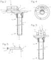
Figures 2, 3 and 4 illustrate a cannula system with LED's and focusing lenses configured to narrow the beam angle of the light transmitted into the cannula tube. -
Figure 5 shows details of the lighting assembly shown ifFigures 1 ,2 and 3 . -
Figure 6, 7 and 8 illustrate a lighting assembly without a prism, in which the optical axis is aligned with the length of the cannula tube. -
Figures 1 ,2 and 3 illustrate a cannula system that may be conveniently used in a minimally invasive surgery.Figure 1 illustrates apatient 1 withdiseased tissue 2 in thebrain 3 that necessitates surgical intervention, with a cannula 4 which has been inserted into diseased tissue, with the distal end of the cannula proximate the diseased tissue. The diseased tissue may be a glioma or glioblastoma in the brain, an ependymoma in the spine, or other diseased tissue. - A
camera 5 is mounted on the proximal rim of the cannula, with a portion of the camera overhanging the rim of the cannula and disposed over the lumen of the cannula, and is operable to obtain video or still images of the distal end of the cannula lumen, including target tissue at the distal end of the cannula such as the brain and any diseased tissue in the brain. As shown in bothFigures 1 and2 and 3 , the cannula comprises acannula tube 6 with adistal end 6d adapted for insertion into the body of the patient. Thecamera assembly 5 is secured to theproximal end 6p of the cannula. The camera assembly includes animaging sensor 7 and a prism, reflector or other mirror structure oroptical element 8, overhanging the lumen 9 of the cannula tube. Preferably, for use in the brain, a portion of the camera assembly, such as the prism, reflector or mirror, extends into the cylindrical space defined by the lumen of the cannula tube and extending proximally beyond the proximal end of the cannula, and is spaced from the proximal end of the cannula, and extends only slightly into the cylindrical space. The distal-most optical surface of the camera assembly, whether it be the distal face of theprism 8 or an objective lens with a viewing axis directed toward the distal end of the cannula, used without a prism, is located at the proximal end of the cannula tube, and preferably disposed proximally of the proximal end of the cannula tube. - As shown in
Figures 2 and 3 , the cannula also includes one ormore lighting assemblies 10 with anoutput beam axis 11. The lighting assemblies includelight sources 12 and associated optics, if any, which in the illustration includeprisms 13 having an output beam axis 14 (which in this embodiment is coincident with theoutput beam axis 11 of the lighting assembly), andlenses 16, which may be used in this configuration to direct light from the light sources into the lumen, aimed at the workspace at the distal end of the cannula tube and toward target tissue.Figure 1 also shows thecontrol system 17, which is configured and operable to operate the light sources, obtain video image data captured by the camera, and generate/translate corresponding video image data for display on thedisplay screen 18. The camera assembly and lighting assemblies may be supported and held proximally to the proximal end of the cannula tube on amounting structure 19, which in this embodiment comprises a ring of larger diameter than the cannula tube, fixed above the proximal end of the cannula tube. -
Figures 2, 3, 4, and 5 illustrate the construction of thelighting assemblies 10. These lighting assemblies include thelight source 12,prism 13 and thelens 16 positioned between the lens and the prism. The light source is characterized by abeam axis 12B, and a broad beam angle α, which may the result of a un-lensed LED, or a packaged LED with a lens configured to focus light from the LED into the broad beam angle. The packaged LED is typically provided in a form that comprises a substrate, the light-emitting diode itself, and a lens covering the light-emitting diode. In the case of a white light LED, the packaged LED may also comprise a phosphor (to convert some blue light from the diode into red and green light, to produce a package that emits white light). A typical beam angle for a packaged LED may be in the range of 30° to 180°. When used in the cannula system ofFigures 1 through 4 , this wide beam angle would result in excessive glare which obscures images obtained with the camera assembly. To reduce this glare, the lens 15 is a focusing lens provided in the form of a convex lens or a gradient index lens (a GRIN lens) or a collimator lens, which functions to focus light from the packaged LED into a narrower beam angle. A suitable combination of packaged LED and lens is (1) a CREE® XQEAWT led and (2) an Edmunds #64-520 GRIN lens available from Edmunds Optics. A GRIN lens is preferred due to its small cross-section (the cross-section perpendicular to its optical axis) for a given focusing power, which facilitates placement of the lighting assembly on the proximal end of the cannula tube. The prism is preferably a right angle prism, but different forms of prism may be used, to accommodate different angles between the optical axis (the long axis, in this example) 16L of the GRIN lens,output beam axis 11 and the central axis 6L of the cannula tube. The overall lighting assembly has an output beam axis which corresponds to a viewing axis of the prism and theoutput beam axis 11 is at an angle to theoptical axis 16L of the focus lens (in the example shown inFigures 2, 3, 4 ). In the case of a right angle prism, the optical axis of the focusing lens may be perpendicular to the viewing axis of the prism. The distal-most optical surface of the lighting assembly, whether it be the distal face of theprism 13 or a distal surface of the focusing lens (where the focusing lens optical axis is directed toward the distal end of the cannula, used without a prism, as shown inFigures 6 and 7 ) is located at the proximal end of the cannula tube, and preferably disposed proximally of the proximal end of the cannula tube. - The lighting assembly may be configured with an
air gap 20 between the packaged LED and the lens and anair 21 gap between the lens and the prism. With this combination using a CREE® XQEAWT led and an Edmunds #64-520 GRIN lens the resultant beam angle β, centered on the lighting assembly beam axis 10B, is about 3.5°. -
Figures 6 and 7 illustrate a lighting assembly without a prism, in which the optical axis (of the focusing lens) 16L is aligned with the length of thecannula tube 6. Other features of this embodiment are similar to the features ofFigures 2 through 4 , including the cannula 4 and thecannula tube 6, thecamera assembly 5 and theprism 8. The LED's are disposed with abeam axis 12B directed distally into the cannula lumen and toward the distal end of the cannula tube, with thelens 16 aligned with itsoptical axis 16L aligned with the LED beam axis and also pointed distally, toward the cannula lumen and the distal end of the cannula tube. In the configuration, the prism is not necessary. The overall lighting assembly in this embodiment has an output beam axis which corresponds to the optical axis of the focus lens, and this output beam axis is directed toward the distal end of the cannula tube. - In the top view of
Figure 7 , the positions of the light sources, and the correspondinglenses 16 andLED light sources 12, along with thecamera assembly 5 and thecamera prism 8, are shown, with the light sources and camera prism overhanging the lumen 9 of thecannula tube 6 to a limited extent, allowing for illumination and visualization of the workspace at the distal end of the cannula tube while also allowing for passage of tools into the workspace, through the cannula tube.Figure 8 shows the relationship between thelighting assembly 10 with thelight source 12 and its beam angle α transmitting light into aGRIN lens 16, with the light leaving the GRIN lens with a narrow beam angle β along the lightingassembly beam axis 11. - The output beam angle may be slightly larger or smaller, depending on the dimensions of the cannula. For a relatively short,
wide cannula 7 cm long with a 16 mm inner diameter, for example, a narrow beam angle of about 10 to 15°, more preferably about 13°, will provide good illumination with reduced glare. For a 14 cm long cannula with a 9 mm inner diameter, a narrow beam angle of about 3 to 5°, more preferably about 3.7°, will provide good illumination with reduced glare. More generally, a configuration of light source and focusing lens providing an output beam angle of less than about 20° may be used to provide good illumination with minimal glare. - The illustrations show a beam axis (the center of light leaving the lens) of the GRIN lens coincident with the optical axis of the GRIN lens, the beam axis may be altered by positioning the LED off-center relative to the longitudinal center of the GRIN lens (which typically is the optical axis). This will cause the output beam axis of the GRIN lens in Figured 6 and 7 to depart from parallel to the optical axis. Thus, placement of the LED, such that the beam axis of the LED is displaced from the optical axis of the GRIN lens will cause the output beam axis of the GRIN lens to be at an axis to the optical axis. The output beam axis may thus be aimed at the center of the distal opening of the cannula, to intersect a central axis (or other feature) of the cannula tube, while the lighting assembly output remains near the circumference of the cannula tube.
- The configurations the lighting assemblies and cannula result in minimal intrusion of the distal-most optical surface of the lighting assembly into the cannula lumen, or the space over the lumen, so that a surgeon may pass surgical tools through the cannula while the lighting assemblies are disposed on the proximal end of the cannula tube to illuminate the surgical field at the distal end of the cannula, and while the camera also has a distal-most optical surface disposed with minimal intrusion into the cannula lumen, or the space over the lumen, so that a surgeon may pass surgical tools through the cannula while the camera is disposed over the proximal end of the cannula. The benefits of the lighting assemblies which provide narrow output beam allow for a camera and one or more lighting assemblies to be provided at the end of a cannula and still allow passage of surgical tubes into the cannula, the cannula system can be configured with one or more lighting assemblies without a camera disposed on the proximal end of the camera, to provide lighting with minimal glare in a cannula to be used with a camera or microscope provided elsewhere.
Claims (11)
- A cannula system for accessing a surgical field, said cannula system comprising:a cannula comprising a cannula tube (6) with a proximal end and a distal end and a lumen (9) extending from the proximal end to the distal end; anda lighting assembly (10) secured to the proximal end of the cannula tube;wherein said lighting assembly comprises a light source (12) and a focusing lens (16), said light source having a first beam axis and a first beam angle (α), said first beam axis aligned with an optical axis (16L) of said focusing lens (16), said lighting assembly (10) having an output beam angle (β) and an output beam axis (11), wherein said output beam axis (11) is directed toward the distal end of the cannula tube (6), whereinsaid output beam angle (β) is smaller than said first beam angle (α);wherein the lumen (9) and lighting assembly (10) are configured to allow passage of surgical tools through the cannula while the lighting assembly (10) is disposed on the proximal end of the cannula tube (6);whereby the lighting assembly (10) provides illumination for the surgical field with reduced glare within the cannula tube (6).
- The cannula system of claim 1, wherein:
a camera assembly (5) secured to the proximal end of the cannula tube, with a portion of the camera assembly overhanging the lumen and extending into the lumen or a cylindrical space defined by the lumen of the cannula tube and extending therefrom. - The cannula system of claim 1 or 2, wherein:
the lighting assembly further comprises a prism (13) disposed on a side of the focusing lens opposite the light source, with the optical axis of the focusing lens aligned with the prism, wherein the output beam axis corresponds to a viewing axis of the prism and the output beam axis is at an angle to the optical axis of the focus lens. - The cannula system of any one of the preceding claims, wherein:
the output beam angle is 20° or less, and preferably 5° or less. - The cannula system of any of claims 1 through 4, wherein:
the output beam axis corresponds to the optical axis of the focusing lens. - The cannula system of any of claims 2 through 5, wherein:
the camera assembly has a distal-most optical surface which is disposed at the proximal end of the cannula tube or proximal to the proximal end of the cannula tube. - The cannula system of any of claims 1 through 6, wherein:
the lighting assembly has a distal-most optical surface which is disposed at the proximal end of the cannula tube or proximal to the proximal end of the cannula tube. - The cannula system of any of claims 1 through 7, wherein:
the focusing lens is a GRIN lens. - The cannula system of any of claims 1 through 7, wherein:
the focusing lens is a convex lens. - The cannula system of any of claims 1 through 4, wherein:
the prism (13) is arranged such that the optical axis of the focusing lens intersects the prism, and the prism reflects light from the focusing lens into the lumen of the cannula tube. - The cannula system of any of claims 1 through 4, wherein:
the optical axis of the focusing lens is perpendicular to a long axis of the cannula tube, and the prism reflects light from the focusing lens into the lumen.
Applications Claiming Priority (2)
| Application Number | Priority Date | Filing Date | Title |
|---|---|---|---|
| US16/550,162 US11529168B2 (en) | 2019-08-23 | 2019-08-23 | Cannula with illumination |
| PCT/US2020/047487 WO2021041245A1 (en) | 2019-08-23 | 2020-08-21 | Cannula with illumination |
Publications (3)
| Publication Number | Publication Date |
|---|---|
| EP4017386A1 EP4017386A1 (en) | 2022-06-29 |
| EP4017386A4 EP4017386A4 (en) | 2023-08-30 |
| EP4017386B1 true EP4017386B1 (en) | 2024-10-09 |
Family
ID=74647494
Family Applications (1)
| Application Number | Title | Priority Date | Filing Date |
|---|---|---|---|
| EP20858227.0A Active EP4017386B1 (en) | 2019-08-23 | 2020-08-21 | Cannula with illumination |
Country Status (8)
| Country | Link |
|---|---|
| US (1) | US11529168B2 (en) |
| EP (1) | EP4017386B1 (en) |
| JP (1) | JP7364782B2 (en) |
| KR (1) | KR20220038815A (en) |
| CN (1) | CN114269420A (en) |
| AU (1) | AU2020461528B2 (en) |
| CA (1) | CA3151635C (en) |
| WO (1) | WO2021041245A1 (en) |
Families Citing this family (4)
| Publication number | Priority date | Publication date | Assignee | Title |
|---|---|---|---|---|
| JP7520836B2 (en) * | 2018-12-06 | 2024-07-23 | リバウンド セラピュティクス コーポレーション | Cannula system including a camera mounted proximally on the cannula and an image generating and control system for rotating the image, and method of using the cannula system - Patents.com |
| JP2023010634A (en) | 2021-07-07 | 2023-01-20 | ニコ コーポレイション | flexible instrument delivery device |
| CN113440269B (en) * | 2021-08-13 | 2022-08-26 | 吉林大学 | Positioning and guiding device for neurosurgical diagnosis and treatment |
| WO2024179399A1 (en) * | 2023-02-27 | 2024-09-06 | 春风化雨(苏州)智能医疗科技有限公司 | Illumination system for surgical operation |
Family Cites Families (18)
| Publication number | Priority date | Publication date | Assignee | Title |
|---|---|---|---|---|
| JPH0622811Y2 (en) * | 1989-05-23 | 1994-06-15 | 旭光学工業株式会社 | Illumination light introduction device for endoscope |
| US5957832A (en) * | 1993-10-08 | 1999-09-28 | Heartport, Inc. | Stereoscopic percutaneous visualization system |
| DE9414957U1 (en) | 1994-05-25 | 1995-09-28 | Lemke, Norbert, 82194 Gröbenzell | Trocar imaging device |
| AU7377400A (en) | 1999-09-13 | 2001-04-17 | Visionscope, Inc. | Miniature endoscope system |
| JP2004167126A (en) | 2002-11-22 | 2004-06-17 | Pentax Corp | Auxiliary light source device for endoscope device |
| DE102004009384B4 (en) * | 2004-02-26 | 2005-12-22 | Olympus Winter & Ibe Gmbh | Video endoscopic system |
| US8480566B2 (en) * | 2004-09-24 | 2013-07-09 | Vivid Medical, Inc. | Solid state illumination for endoscopy |
| US9005115B2 (en) | 2005-04-04 | 2015-04-14 | Invuity, Inc. | Illuminated telescoping cannula |
| US20090234195A1 (en) * | 2008-03-14 | 2009-09-17 | Prodisc Technology Inc. | Minimal incision surgical light source module with light-emitting diodes |
| WO2011143500A2 (en) * | 2010-05-13 | 2011-11-17 | Doheny Eye Institute | Self contained illuminated infusion cannula systems and devices |
| CN105813541A (en) * | 2014-02-17 | 2016-07-27 | 奥林巴斯株式会社 | Optical fibre connector device, and endoscope system |
| US20170280988A1 (en) * | 2014-04-02 | 2017-10-05 | Visionscope Technologies Llc | Devices and methods for minimally invasive surgery |
| EP3226799A4 (en) * | 2014-12-05 | 2018-07-25 | Camplex, Inc. | Surgical visualization systems and displays |
| US10067056B2 (en) * | 2015-01-06 | 2018-09-04 | Ricoh Company, Ltd. | Optical sensor, optical inspection device, and optical property detection method for detecting light propagated inside a test object |
| US9955852B2 (en) | 2015-03-30 | 2018-05-01 | Acclarent, Inc. | Guide catheter with image capture and light emission features |
| US10172525B2 (en) * | 2015-08-17 | 2019-01-08 | Rebound Therapeutics Corporation | Cannula with proximally mounted camera |
| US10376281B2 (en) * | 2016-08-17 | 2019-08-13 | Rebound Therapeutics Corporation | Cannula with proximally mounted camera |
| US10105042B2 (en) * | 2016-08-17 | 2018-10-23 | Rebound Therapeutics Corporation | Cannula with proximally mounted camera |
-
2019
- 2019-08-23 US US16/550,162 patent/US11529168B2/en active Active
-
2020
- 2020-08-21 EP EP20858227.0A patent/EP4017386B1/en active Active
- 2020-08-21 JP JP2022505621A patent/JP7364782B2/en active Active
- 2020-08-21 CN CN202080058092.2A patent/CN114269420A/en active Pending
- 2020-08-21 AU AU2020461528A patent/AU2020461528B2/en active Active
- 2020-08-21 CA CA3151635A patent/CA3151635C/en active Active
- 2020-08-21 WO PCT/US2020/047487 patent/WO2021041245A1/en not_active Ceased
- 2020-08-21 KR KR1020227008424A patent/KR20220038815A/en not_active Ceased
Also Published As
| Publication number | Publication date |
|---|---|
| CA3151635A1 (en) | 2021-03-04 |
| JP2022536865A (en) | 2022-08-19 |
| US11529168B2 (en) | 2022-12-20 |
| JP7364782B2 (en) | 2023-10-18 |
| CN114269420A (en) | 2022-04-01 |
| US20210052299A1 (en) | 2021-02-25 |
| AU2020461528B2 (en) | 2022-09-15 |
| KR20220038815A (en) | 2022-03-29 |
| EP4017386A1 (en) | 2022-06-29 |
| WO2021041245A1 (en) | 2021-03-04 |
| CA3151635C (en) | 2025-05-13 |
| EP4017386A4 (en) | 2023-08-30 |
| AU2020461528A1 (en) | 2022-04-07 |
Similar Documents
| Publication | Publication Date | Title |
|---|---|---|
| CA3151635C (en) | Cannula with illumination | |
| CN111479533B (en) | Illuminated multi-point laser probe with multiple input coupling | |
| EP1804640B1 (en) | Solid state illumination for endoscopy | |
| US10398318B2 (en) | Cannula with proximally mounted camera | |
| EP3599983B1 (en) | Endoscopes | |
| US20040092958A1 (en) | Stereotactic wands, endoscopes and methods using such wands and endoscopes | |
| US8128231B2 (en) | Enhanced lifetime illuminator | |
| US10806536B2 (en) | Physician-safe illumination in ophthalmic surgeries | |
| US20210052300A1 (en) | Cannula and obturator system | |
| US12582318B2 (en) | Illumination unit and medical imaging system for fluorescence imaging in open surgery | |
| US20240268674A1 (en) | Illumination system and medical imaging system for fluorescence imaging in open surgery | |
| US20260013708A1 (en) | Filter device and endoscope system | |
| WO2025015162A1 (en) | Removable endoscope cap including a filter for improved stone free rate | |
| WO2002039877A2 (en) | Stereotactic wands, endoscopes, and methods using such wands and endoscopes |
Legal Events
| Date | Code | Title | Description |
|---|---|---|---|
| STAA | Information on the status of an ep patent application or granted ep patent |
Free format text: STATUS: THE INTERNATIONAL PUBLICATION HAS BEEN MADE |
|
| PUAI | Public reference made under article 153(3) epc to a published international application that has entered the european phase |
Free format text: ORIGINAL CODE: 0009012 |
|
| STAA | Information on the status of an ep patent application or granted ep patent |
Free format text: STATUS: REQUEST FOR EXAMINATION WAS MADE |
|
| 17P | Request for examination filed |
Effective date: 20220323 |
|
| AK | Designated contracting states |
Kind code of ref document: A1 Designated state(s): AL AT BE BG CH CY CZ DE DK EE ES FI FR GB GR HR HU IE IS IT LI LT LU LV MC MK MT NL NO PL PT RO RS SE SI SK SM TR |
|
| DAV | Request for validation of the european patent (deleted) | ||
| DAX | Request for extension of the european patent (deleted) | ||
| P01 | Opt-out of the competence of the unified patent court (upc) registered |
Effective date: 20230518 |
|
| A4 | Supplementary search report drawn up and despatched |
Effective date: 20230727 |
|
| RIC1 | Information provided on ipc code assigned before grant |
Ipc: A61B 5/00 20060101ALI20230721BHEP Ipc: G03B 15/05 20210101ALI20230721BHEP Ipc: G03B 15/14 20210101ALI20230721BHEP Ipc: H04N 23/57 20230101ALI20230721BHEP Ipc: H04N 23/56 20230101ALI20230721BHEP Ipc: H04N 23/50 20230101ALI20230721BHEP Ipc: A61B 1/06 20060101ALI20230721BHEP Ipc: A61B 90/14 20160101ALI20230721BHEP Ipc: A61B 90/11 20160101ALI20230721BHEP Ipc: A61B 1/04 20060101ALI20230721BHEP Ipc: A61B 90/30 20160101ALI20230721BHEP Ipc: A61B 1/313 20060101ALI20230721BHEP Ipc: A61B 5/02 20060101ALI20230721BHEP Ipc: A61B 17/34 20060101AFI20230721BHEP |
|
| GRAP | Despatch of communication of intention to grant a patent |
Free format text: ORIGINAL CODE: EPIDOSNIGR1 |
|
| STAA | Information on the status of an ep patent application or granted ep patent |
Free format text: STATUS: GRANT OF PATENT IS INTENDED |
|
| INTG | Intention to grant announced |
Effective date: 20240510 |
|
| GRAS | Grant fee paid |
Free format text: ORIGINAL CODE: EPIDOSNIGR3 |
|
| GRAA | (expected) grant |
Free format text: ORIGINAL CODE: 0009210 |
|
| STAA | Information on the status of an ep patent application or granted ep patent |
Free format text: STATUS: THE PATENT HAS BEEN GRANTED |
|
| AK | Designated contracting states |
Kind code of ref document: B1 Designated state(s): AL AT BE BG CH CY CZ DE DK EE ES FI FR GB GR HR HU IE IS IT LI LT LU LV MC MK MT NL NO PL PT RO RS SE SI SK SM TR |
|
| REG | Reference to a national code |
Ref country code: CH Ref legal event code: EP |
|
| REG | Reference to a national code |
Ref country code: DE Ref legal event code: R096 Ref document number: 602020039296 Country of ref document: DE |
|
| REG | Reference to a national code |
Ref country code: IE Ref legal event code: FG4D |
|
| REG | Reference to a national code |
Ref country code: LT Ref legal event code: MG9D |
|
| REG | Reference to a national code |
Ref country code: NL Ref legal event code: MP Effective date: 20241009 |
|
| REG | Reference to a national code |
Ref country code: AT Ref legal event code: MK05 Ref document number: 1729709 Country of ref document: AT Kind code of ref document: T Effective date: 20241009 |
|
| PG25 | Lapsed in a contracting state [announced via postgrant information from national office to epo] |
Ref country code: NL Free format text: LAPSE BECAUSE OF FAILURE TO SUBMIT A TRANSLATION OF THE DESCRIPTION OR TO PAY THE FEE WITHIN THE PRESCRIBED TIME-LIMIT Effective date: 20241009 |
|
| PG25 | Lapsed in a contracting state [announced via postgrant information from national office to epo] |
Ref country code: NL Free format text: LAPSE BECAUSE OF FAILURE TO SUBMIT A TRANSLATION OF THE DESCRIPTION OR TO PAY THE FEE WITHIN THE PRESCRIBED TIME-LIMIT Effective date: 20241009 |
|
| PG25 | Lapsed in a contracting state [announced via postgrant information from national office to epo] |
Ref country code: PT Free format text: LAPSE BECAUSE OF FAILURE TO SUBMIT A TRANSLATION OF THE DESCRIPTION OR TO PAY THE FEE WITHIN THE PRESCRIBED TIME-LIMIT Effective date: 20250210 Ref country code: IS Free format text: LAPSE BECAUSE OF FAILURE TO SUBMIT A TRANSLATION OF THE DESCRIPTION OR TO PAY THE FEE WITHIN THE PRESCRIBED TIME-LIMIT Effective date: 20250209 Ref country code: HR Free format text: LAPSE BECAUSE OF FAILURE TO SUBMIT A TRANSLATION OF THE DESCRIPTION OR TO PAY THE FEE WITHIN THE PRESCRIBED TIME-LIMIT Effective date: 20241009 |
|
| PG25 | Lapsed in a contracting state [announced via postgrant information from national office to epo] |
Ref country code: FI Free format text: LAPSE BECAUSE OF FAILURE TO SUBMIT A TRANSLATION OF THE DESCRIPTION OR TO PAY THE FEE WITHIN THE PRESCRIBED TIME-LIMIT Effective date: 20241009 |
|
| PG25 | Lapsed in a contracting state [announced via postgrant information from national office to epo] |
Ref country code: BG Free format text: LAPSE BECAUSE OF FAILURE TO SUBMIT A TRANSLATION OF THE DESCRIPTION OR TO PAY THE FEE WITHIN THE PRESCRIBED TIME-LIMIT Effective date: 20241009 |
|
| PG25 | Lapsed in a contracting state [announced via postgrant information from national office to epo] |
Ref country code: ES Free format text: LAPSE BECAUSE OF FAILURE TO SUBMIT A TRANSLATION OF THE DESCRIPTION OR TO PAY THE FEE WITHIN THE PRESCRIBED TIME-LIMIT Effective date: 20241009 |
|
| PG25 | Lapsed in a contracting state [announced via postgrant information from national office to epo] |
Ref country code: NO Free format text: LAPSE BECAUSE OF FAILURE TO SUBMIT A TRANSLATION OF THE DESCRIPTION OR TO PAY THE FEE WITHIN THE PRESCRIBED TIME-LIMIT Effective date: 20250109 |
|
| PG25 | Lapsed in a contracting state [announced via postgrant information from national office to epo] |
Ref country code: LV Free format text: LAPSE BECAUSE OF FAILURE TO SUBMIT A TRANSLATION OF THE DESCRIPTION OR TO PAY THE FEE WITHIN THE PRESCRIBED TIME-LIMIT Effective date: 20241009 Ref country code: GR Free format text: LAPSE BECAUSE OF FAILURE TO SUBMIT A TRANSLATION OF THE DESCRIPTION OR TO PAY THE FEE WITHIN THE PRESCRIBED TIME-LIMIT Effective date: 20250110 Ref country code: AT Free format text: LAPSE BECAUSE OF FAILURE TO SUBMIT A TRANSLATION OF THE DESCRIPTION OR TO PAY THE FEE WITHIN THE PRESCRIBED TIME-LIMIT Effective date: 20241009 |
|
| PG25 | Lapsed in a contracting state [announced via postgrant information from national office to epo] |
Ref country code: PL Free format text: LAPSE BECAUSE OF FAILURE TO SUBMIT A TRANSLATION OF THE DESCRIPTION OR TO PAY THE FEE WITHIN THE PRESCRIBED TIME-LIMIT Effective date: 20241009 |
|
| PG25 | Lapsed in a contracting state [announced via postgrant information from national office to epo] |
Ref country code: RS Free format text: LAPSE BECAUSE OF FAILURE TO SUBMIT A TRANSLATION OF THE DESCRIPTION OR TO PAY THE FEE WITHIN THE PRESCRIBED TIME-LIMIT Effective date: 20250109 |
|
| PG25 | Lapsed in a contracting state [announced via postgrant information from national office to epo] |
Ref country code: SM Free format text: LAPSE BECAUSE OF FAILURE TO SUBMIT A TRANSLATION OF THE DESCRIPTION OR TO PAY THE FEE WITHIN THE PRESCRIBED TIME-LIMIT Effective date: 20241009 |
|
| PG25 | Lapsed in a contracting state [announced via postgrant information from national office to epo] |
Ref country code: DK Free format text: LAPSE BECAUSE OF FAILURE TO SUBMIT A TRANSLATION OF THE DESCRIPTION OR TO PAY THE FEE WITHIN THE PRESCRIBED TIME-LIMIT Effective date: 20241009 |
|
| REG | Reference to a national code |
Ref country code: DE Ref legal event code: R097 Ref document number: 602020039296 Country of ref document: DE |
|
| PG25 | Lapsed in a contracting state [announced via postgrant information from national office to epo] |
Ref country code: EE Free format text: LAPSE BECAUSE OF FAILURE TO SUBMIT A TRANSLATION OF THE DESCRIPTION OR TO PAY THE FEE WITHIN THE PRESCRIBED TIME-LIMIT Effective date: 20241009 |
|
| PGFP | Annual fee paid to national office [announced via postgrant information from national office to epo] |
Ref country code: FR Payment date: 20250610 Year of fee payment: 6 |
|
| PG25 | Lapsed in a contracting state [announced via postgrant information from national office to epo] |
Ref country code: RO Free format text: LAPSE BECAUSE OF FAILURE TO SUBMIT A TRANSLATION OF THE DESCRIPTION OR TO PAY THE FEE WITHIN THE PRESCRIBED TIME-LIMIT Effective date: 20241009 |
|
| PG25 | Lapsed in a contracting state [announced via postgrant information from national office to epo] |
Ref country code: SK Free format text: LAPSE BECAUSE OF FAILURE TO SUBMIT A TRANSLATION OF THE DESCRIPTION OR TO PAY THE FEE WITHIN THE PRESCRIBED TIME-LIMIT Effective date: 20241009 |
|
| PG25 | Lapsed in a contracting state [announced via postgrant information from national office to epo] |
Ref country code: CZ Free format text: LAPSE BECAUSE OF FAILURE TO SUBMIT A TRANSLATION OF THE DESCRIPTION OR TO PAY THE FEE WITHIN THE PRESCRIBED TIME-LIMIT Effective date: 20241009 |
|
| PLBE | No opposition filed within time limit |
Free format text: ORIGINAL CODE: 0009261 |
|
| STAA | Information on the status of an ep patent application or granted ep patent |
Free format text: STATUS: NO OPPOSITION FILED WITHIN TIME LIMIT |
|
| PG25 | Lapsed in a contracting state [announced via postgrant information from national office to epo] |
Ref country code: SE Free format text: LAPSE BECAUSE OF FAILURE TO SUBMIT A TRANSLATION OF THE DESCRIPTION OR TO PAY THE FEE WITHIN THE PRESCRIBED TIME-LIMIT Effective date: 20241009 |
|
| 26N | No opposition filed |
Effective date: 20250710 |
|
| PGFP | Annual fee paid to national office [announced via postgrant information from national office to epo] |
Ref country code: DE Payment date: 20250624 Year of fee payment: 6 |
|
| PGFP | Annual fee paid to national office [announced via postgrant information from national office to epo] |
Ref country code: IT Payment date: 20250722 Year of fee payment: 6 |
|
| PGFP | Annual fee paid to national office [announced via postgrant information from national office to epo] |
Ref country code: GB Payment date: 20250703 Year of fee payment: 6 |
|
| REG | Reference to a national code |
Ref country code: CH Ref legal event code: H13 Free format text: ST27 STATUS EVENT CODE: U-0-0-H10-H13 (AS PROVIDED BY THE NATIONAL OFFICE) Effective date: 20260324 |
|
| PG25 | Lapsed in a contracting state [announced via postgrant information from national office to epo] |
Ref country code: MC Free format text: LAPSE BECAUSE OF FAILURE TO SUBMIT A TRANSLATION OF THE DESCRIPTION OR TO PAY THE FEE WITHIN THE PRESCRIBED TIME-LIMIT Effective date: 20241009 |
|
| PG25 | Lapsed in a contracting state [announced via postgrant information from national office to epo] |
Ref country code: LU Free format text: LAPSE BECAUSE OF NON-PAYMENT OF DUE FEES Effective date: 20250821 |
|
| PG25 | Lapsed in a contracting state [announced via postgrant information from national office to epo] |
Ref country code: CH Free format text: LAPSE BECAUSE OF NON-PAYMENT OF DUE FEES Effective date: 20250831 |