EP4017034B1 - 5g positioning slam tags - Google Patents
5g positioning slam tags Download PDFInfo
- Publication number
- EP4017034B1 EP4017034B1 EP20215912.5A EP20215912A EP4017034B1 EP 4017034 B1 EP4017034 B1 EP 4017034B1 EP 20215912 A EP20215912 A EP 20215912A EP 4017034 B1 EP4017034 B1 EP 4017034B1
- Authority
- EP
- European Patent Office
- Prior art keywords
- tag
- area
- base station
- bluetooth
- control entity
- Prior art date
- Legal status (The legal status is an assumption and is not a legal conclusion. Google has not performed a legal analysis and makes no representation as to the accuracy of the status listed.)
- Active
Links
Images


Classifications
-
- H—ELECTRICITY
- H04—ELECTRIC COMMUNICATION TECHNIQUE
- H04W—WIRELESS COMMUNICATION NETWORKS
- H04W4/00—Services specially adapted for wireless communication networks; Facilities therefor
- H04W4/02—Services making use of location information
-
- G—PHYSICS
- G01—MEASURING; TESTING
- G01C—MEASURING DISTANCES, LEVELS OR BEARINGS; SURVEYING; NAVIGATION; GYROSCOPIC INSTRUMENTS; PHOTOGRAMMETRY OR VIDEOGRAMMETRY
- G01C21/00—Navigation; Navigational instruments not provided for in groups G01C1/00 - G01C19/00
- G01C21/20—Instruments for performing navigational calculations
- G01C21/206—Instruments for performing navigational calculations specially adapted for indoor navigation
-
- G—PHYSICS
- G01—MEASURING; TESTING
- G01S—RADIO DIRECTION-FINDING; RADIO NAVIGATION; DETERMINING DISTANCE OR VELOCITY BY USE OF RADIO WAVES; LOCATING OR PRESENCE-DETECTING BY USE OF THE REFLECTION OR RERADIATION OF RADIO WAVES; ANALOGOUS ARRANGEMENTS USING OTHER WAVES
- G01S5/00—Position-fixing by co-ordinating two or more direction or position line determinations; Position-fixing by co-ordinating two or more distance determinations
- G01S5/02—Position-fixing by co-ordinating two or more direction or position line determinations; Position-fixing by co-ordinating two or more distance determinations using radio waves
- G01S5/0284—Relative positioning
-
- G—PHYSICS
- G01—MEASURING; TESTING
- G01S—RADIO DIRECTION-FINDING; RADIO NAVIGATION; DETERMINING DISTANCE OR VELOCITY BY USE OF RADIO WAVES; LOCATING OR PRESENCE-DETECTING BY USE OF THE REFLECTION OR RERADIATION OF RADIO WAVES; ANALOGOUS ARRANGEMENTS USING OTHER WAVES
- G01S5/00—Position-fixing by co-ordinating two or more direction or position line determinations; Position-fixing by co-ordinating two or more distance determinations
- G01S5/02—Position-fixing by co-ordinating two or more direction or position line determinations; Position-fixing by co-ordinating two or more distance determinations using radio waves
- G01S5/0295—Proximity-based methods, e.g. position inferred from reception of particular signals
-
- H—ELECTRICITY
- H04—ELECTRIC COMMUNICATION TECHNIQUE
- H04L—TRANSMISSION OF DIGITAL INFORMATION, e.g. TELEGRAPHIC COMMUNICATION
- H04L67/00—Network arrangements or protocols for supporting network services or applications
- H04L67/50—Network services
- H04L67/52—Network services specially adapted for the location of the user terminal
-
- H—ELECTRICITY
- H04—ELECTRIC COMMUNICATION TECHNIQUE
- H04W—WIRELESS COMMUNICATION NETWORKS
- H04W4/00—Services specially adapted for wireless communication networks; Facilities therefor
- H04W4/02—Services making use of location information
- H04W4/021—Services related to particular areas, e.g. point of interest [POI] services, venue services or geofences
-
- H—ELECTRICITY
- H04—ELECTRIC COMMUNICATION TECHNIQUE
- H04W—WIRELESS COMMUNICATION NETWORKS
- H04W4/00—Services specially adapted for wireless communication networks; Facilities therefor
- H04W4/02—Services making use of location information
- H04W4/023—Services making use of location information using mutual or relative location information between multiple location based services [LBS] targets or of distance thresholds
-
- H—ELECTRICITY
- H04—ELECTRIC COMMUNICATION TECHNIQUE
- H04W—WIRELESS COMMUNICATION NETWORKS
- H04W4/00—Services specially adapted for wireless communication networks; Facilities therefor
- H04W4/02—Services making use of location information
- H04W4/025—Services making use of location information using location based information parameters
-
- H—ELECTRICITY
- H04—ELECTRIC COMMUNICATION TECHNIQUE
- H04W—WIRELESS COMMUNICATION NETWORKS
- H04W4/00—Services specially adapted for wireless communication networks; Facilities therefor
- H04W4/02—Services making use of location information
- H04W4/029—Location-based management or tracking services
-
- H—ELECTRICITY
- H04—ELECTRIC COMMUNICATION TECHNIQUE
- H04L—TRANSMISSION OF DIGITAL INFORMATION, e.g. TELEGRAPHIC COMMUNICATION
- H04L67/00—Network arrangements or protocols for supporting network services or applications
- H04L67/01—Protocols
- H04L67/12—Protocols specially adapted for proprietary or special-purpose networking environments, e.g. medical networks, sensor networks, networks in vehicles or remote metering networks
-
- H—ELECTRICITY
- H04—ELECTRIC COMMUNICATION TECHNIQUE
- H04W—WIRELESS COMMUNICATION NETWORKS
- H04W4/00—Services specially adapted for wireless communication networks; Facilities therefor
- H04W4/30—Services specially adapted for particular environments, situations or purposes
-
- H—ELECTRICITY
- H04—ELECTRIC COMMUNICATION TECHNIQUE
- H04W—WIRELESS COMMUNICATION NETWORKS
- H04W4/00—Services specially adapted for wireless communication networks; Facilities therefor
- H04W4/30—Services specially adapted for particular environments, situations or purposes
- H04W4/33—Services specially adapted for particular environments, situations or purposes for indoor environments, e.g. buildings
-
- H—ELECTRICITY
- H04—ELECTRIC COMMUNICATION TECHNIQUE
- H04W—WIRELESS COMMUNICATION NETWORKS
- H04W4/00—Services specially adapted for wireless communication networks; Facilities therefor
- H04W4/30—Services specially adapted for particular environments, situations or purposes
- H04W4/40—Services specially adapted for particular environments, situations or purposes for vehicles, e.g. vehicle-to-pedestrians [V2P]
-
- H—ELECTRICITY
- H04—ELECTRIC COMMUNICATION TECHNIQUE
- H04W—WIRELESS COMMUNICATION NETWORKS
- H04W4/00—Services specially adapted for wireless communication networks; Facilities therefor
- H04W4/80—Services using short range communication, e.g. near-field communication [NFC], radio-frequency identification [RFID] or low energy communication
-
- H—ELECTRICITY
- H04—ELECTRIC COMMUNICATION TECHNIQUE
- H04W—WIRELESS COMMUNICATION NETWORKS
- H04W88/00—Devices specially adapted for wireless communication networks, e.g. terminals, base stations or access point devices
- H04W88/02—Terminal devices
Definitions
- the present invention relates to 5G positioning, in particular to 5G positioning using simultaneous localisation and mapping (SLAM) tags.
- SLAM simultaneous localisation and mapping
- omlox's target is the standardization the industrial UWB RTLS (the omlox core zone) and make different localization technologies interoperable (the omlox hub).
- FiRa on the other hand defines the fine ranging using UWB between tags equipped with UWB chips for a mobile mesh.
- WO 2018/145154 A1 discloses displaying content to users in a multiplayer venue.
- the present disclosure relates to a system for simultaneous localisation and mapping (SLAM) of an object in an area.
- the system comprises at least one base station and at least one user equipment (UE) configured to communicate with the at least one base station.
- the system further comprises at least one object to be localised, wherein the at least one object each comprises an identification tag (ID tag).
- ID tag identification tag
- the at least one UE is configured to localise the at least one object via the respective ID tag.
- the at least one base station is configured to localise the at least one UE in the area based on 5G communication.
- the at least one UE is configured to transmit a relative position of the at least one object with respect to the at least one UE to the base station.
- the system further comprises a control entity configured to communicate with the at least one UE and the at least one base station to receive the position of the at least one UE from the base station and the relative position of the at least one object from the UE, wherein the control entity is further configured to generate a map of the received position of the at least one object in the area.
- a control entity configured to communicate with the at least one UE and the at least one base station to receive the position of the at least one UE from the base station and the relative position of the at least one object from the UE, wherein the control entity is further configured to generate a map of the received position of the at least one object in the area.
- the at least one UE and the at least one ID tag each comprise a Bluetooth Low Energy (Bluetooth LE) transceiver and the at least one UE is configured to localise the at least one object via the respective ID tag using Bluetooth LE.
- Bluetooth LE Bluetooth Low Energy
- the at least one UE and the at least one ID tag each comprise an Ultra Wide Band (UWB) transceiver and the at least one UE is configured to localise the at least one object via the respective ID tag using UWB.
- UWB Ultra Wide Band
- the at least one object is an active object configured to actively move in the area or a passive object configured to be stationary or to be moved in the area.
- the at least one active object comprises a 5G transceiver and/or a Bluetooth Low Energy, Bluetooth LE, transceiver and/or an Ultra Wide Band, UWB, transceiver.
- the at least one UE is preferably configured to localise the at least one active object using 5G and/or Bluetooth LE and/or UWB.
- the at least one passive object each may comprise the ID tag.
- At least one fixed 5G tag is positioned in the area, wherein the at least one UE and/or the control entity is configured to generate additional localisation information of a relative position of the at least one UE with respect to the at least one 5G tag via communication with the at least one 5G tag.
- the at least one UE and/or the at least one ID tag and/or the at least one 5G tag are configured to perform encrypted communication.
- the at least one UE is additionally localised by the at least one UE using Global Positioning System, GPS, wherein the at least one UE is configured to transmit the respective position to the control entity.
- GPS Global Positioning System
- the active object is at least one of an automated guided vehicle, AGV, a forklift, a truck, or an operator and/or the passive object is at least one of material, a tool, storage space or loading equipment.
- the UE is configured to guide a user of the UE to a desired object being localised.
- the present disclosure also encompasses a method for simultaneous localisation and mapping (SLAM) of an object in an area for use in a system as described above.
- the method comprises localising, based on 5G communication, at least one user equipment (UE) in the area via at least one base station and localising, by the at least one UE, at least one object to be localised, wherein the at least one object comprises an identification tag (ID tag) and the localisation is performed based on the identification tag (ID tag).
- a relative position of the localised object with regard to the UE is sent by the at least one UE to the at least one base station and a control entity, and the position of the UE is sent by the base station to the control entity.
- the control entity generates a map of a position of the at least one object in the area using the position of the UE and the relative position of the object.
- the method further comprises localising, by the UE, the at least one object via the respective ID tag using Bluetooth Low Energy, Bluetooth LE, and/or using Ultra Wide Band, UWB.
- the at least one object to be localised is an active object configured to actively move in the area or a passive object configured to be stationary or to be moved in the area and the method further comprises localising the at least one passive object via the respective ID tag, and/or localising the at least one active object using 5G and/or Bluetooth LE and/or UWB.
- the base station, UE and object may each be provided singular or in plurality.
- a facility may describe any confined area such as a campus, a storage building, a manufacturing facility, production hall, etc. in which an object localisation as described may be performed.
- Fig. 1 shows a basic configuration of an example according to the present disclosure.
- a system 1 comprising at least one base station 2, at least one UE 3, at least one object 4 and a control entity 5.
- An object 4 may also be referred to as asset.
- Each of the at least one objects 4 comprises an identification (ID) tag 6.
- ID tag 6 can form part of the object itself or may be detachably provided.
- the ID tag 6 may be an active device or a passive device.
- the at least one object 4 may be an active object or subject, i.e.
- an object or subject which is moving such as an automated guided vehicle (AGV), a forklift, a workman, a truck, etc., or a passive object which may either be stationary or may be passively moved in the facility such as tools, material, load carrier, storage space, etc.
- AGV automated guided vehicle
- a forklift a workman
- a truck a truck
- passive object which may either be stationary or may be passively moved in the facility such as tools, material, load carrier, storage space, etc.
- the system according to the example employs a combination of Fine Ranging (FiRa), particularly a FiRa mobile mesh, and 5G positioning. Therefore, a 5G network is set up in the facility or the campus, respectively, by at least one base station 2.
- the 5G network is limited to the facility itself and allows positioning of user equipment (UE) 3, i.e. mobile devices such as smartphones and other handheld devices, indoors and outdoors.
- UE user equipment
- the localisation accuracy is normally around 2 - 3m.
- GPS Global Positioning System
- GPS Global Positioning System
- the UEs 3 comprise 5G network as well as UWB capability, e.g. a FiRa UWB (IEEE 802.15.4z-2020 standard conform) chip, and Bluetooth LE functionality.
- the objects 4 on the other hand comprise respective means for transmitting and/or receiving 5G, UWB and/or Bluetooth LE communication.
- identification (ID) tags 6 in particular 5G ID tags or 5G positioning SLAM tags, may be employed.
- the ID tags 6 may be detachably provided on objects 4 and thus allow localisation of the respective objects 4. Estimation of the distance of an object 4 or ID tag 6 can be done, e.g., via received signal strength indicator (RSSI).
- RSSI received signal strength indicator
- the ID tags 6 can be passive devices or low-power devices, this provides a cost effective and long-living localisation of objects 4 on the campus.
- Each of the UEs 3 is thereby capable of localising all objects 4.
- the ID tags 6 as well as the UEs 3 may be encrypted, e.g. via a key (not shown).
- a key not shown
- an application may be provided on the UE 3 allowing for decrypting and localising the keys and the respective ID tags 6 and objects 4.
- Active objects 4 may be UEs 3 themselves which can be localised by other UEs 3. Active objects 4 such as moving objects may also comprise a 5G transceiver and/or Bluetooth LE transceiver and/or UWB transceiver allowing the active objects 4 to be localised by UEs 3 or base stations 2. Preferably, passive objects 4 are localised using ID tags 6 while active objects 4 are localised using 5G and/or Bluetooth LE and/or UWB. An active object 4 may also report, i.e. transmit, its position to a UE 3 or a base station 2.
- a control entity 5 is configured to communicate with at least one of the base station 2, the UE 3 or the object 4 to determine a position of the UE 3 and/or the object.
- An exemplary localisation sequence can be described as follows.
- the at least one UE 3 is localised via 5G, i.e. through the at least one base station 2 and the respective 5G campus positioning network. Localisation is, if necessary, supported by GPS.
- the UE 3 regularly checks, e.g. via Bluetooth LE, whether ID tags 6, i.e. objects 4, are in the proximity of the UE 3. For objects 4 in Bluetooth LE range, an exact localisation is then performed using UWB which provides an accuracy in the range of centimetres.
- the control entity 5 communicates with the at least one base station 2 and/or the at least one UE 3 and/or the at least one object 4.
- the control entity 5 is configured to determine relative and/or absolute positions of the at least one UE 3 and/or the at least one object 4.
- Position determination is performed by a campus SLAM algorithm which generates a map (asset map) with real-time locations of active and passive objects 4.
- an edge computing algorithm i.e. a local (decentralised) computing algorithm on facility level, is employed for position determination and map generation.
- a cloud-based computation for a plurality of facilities i.e. on company level rather than facility level, may also be used.
- Searching an object 4 is performed via a UE 3 which is operated by a user.
- the user inputs the searched object 4 which is localised on the campus as described above.
- the UE 3 can then be used to navigate a user to the position of the searched object 4.
- the UE 3 may therefore comprise a navigation program or an application for guiding a user inside the facility. Navigation is first performed on a coarse level, where the user is guided to the area of the searched object 4, and then a refined localisation is performed via precise ranging. As described above, coarse localisation is performed using 5G, and GPS if necessary, while precise ranging is performed using Bluetooth LE and/or UWB.
- the UE 3 can also access the asset map generated by the control entity 5 or itself generate an asset map for the user. Moreover, a mapping of objects 4 and ID tags 6 can be performed via the UE 3 or the control entity 5. Additional information in relation to the ID tags 6 and/or objects 4 may be displayed as a location-based service. Hence, the user is able to localise a searched object 4, navigate to the searched object 4 and receive information on the searched object 4.
- localisation of the UE 3 may be improved by fixed 5G ID tags which are distributed in the facility.
- the 5G ID tags may be similar or identical to the ID tags 6 of the objects 4.
- the position of the UE 3 can be accurately determined using the base station 2 and preferably at least two 5G ID tags. This especially improves localisation performance in metallic environments having a high amount of reflections.
- the method for simultaneous localisation and mapping comprises localising S1, based on 5G communication, at least one user equipment, UE, in the area via at least one base station.
- the at least one UE localises S2 at least one object to be localised based on an identification, ID, tag.
- the at least one UE sends S3 a relative position of the localised object with regard to the UE to the at least one base station.
- the at least one base station sends S4 the position of the UE to a control entity.
- the control entity generates S5 a map of a position of the at least one object in the area using the position of the UE and the relative position of the object.
- Fig. 3 is a depiction of a use case of the system and sequence as described above in a facility.
- the facility is indicated by the rectangular lines, the circles denote a key 7 as mentioned above.
- Keys 7 may be provided to UEs 3, ID tags 6 and objects 4.
- Communication paths are indicated by arrows.
- a 5G network is spanned by the base stations 2, wherein absolute positions of the UEs 3 can be determined using the 5G network.
- Each UE 3 is capable of 5G communication and is further equipped with an UWB chip, preferably compatible with the IEEE 802.15.4z-2020 standard, as well as a Bluetooth LE chip.
- a plurality of ID tags 6 are distributed in the facility indicating the position of an object 4 (not shown).
- Each of the UEs 3 and the ID tags 6 comprises a key 7 which is encrypted particularly for the facility based on UWB and/or Bluetooth LE and allows secure communication only for authorised devices. That is, only UEs 3 having an application and a valid key 7 may localise ID tags 6.
- the UEs 3 can determine a relative location of an ID tag 6, i.e. a location with reference to the respective UE 3, via UWB and/or BLE and communicate the relative location to the control entity 5.
- the control entity 5 can also directly communicate with the ID tags 6.
- the control entity can also directly communicate with the base station 2.
- the control entity 5 can therefore compute the absolute positions of the UEs 3 and, using the relative position information of the ID tags 6 gathered by the UEs 3, the absolute positions of the ID tags 6 and the respective objects 4.
- the control entity 5 is thus also capable of generating a map of the positions of each of the UEs 3 and the ID tags 6.
- a user can thus, using a UE 3, search for an object 4 and retrieve the position from the control entity 5. Subsequently, the user can be guided to the respective position by the UE 3. Alternatively, the user may go through the facility and check which objects 4 are in the proximity of the user via the UE 3 using 5G and/or UWB and/or Bluetooth LE and/or the map generated by the control entity 5.
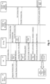
- control entity 5 is divided in a control entity encryption and a control entity SLAM algorithm. However, this is for illustrative purposes and they may also be provided in a single control entity 5 or a plurality of single interconnected entities. Arrows illustrate communication between the entities and, if applicable, the direction of communication. The time flow of the described processes goes from top to bottom.
- Fig. 4 shows the general working principle of ID tags 6 according to an example of the present disclosure.
- a UE 3 requests a campus key 7 from the control entity encryption and receives the respective key 7.
- an ID tag 6 requests a campus key 7 from the control entity encryption and receives the respective key 7.
- the UE 3 requests its position from the base station 2 and receives a position, e.g. latitude and longitude, from the base station 2. This may be performed in fixed or variable intervals.
- the control entity SLAM algorithm request and receives the campus key 7 from the control entity encryption.
- the UE 3 is further configured to sense or search for ID tags 6 via Bluetooth LE.
- the Bluetooth LE device is referred to as BLE listener.
- the respective ID tags 6 provide an identification (ID) and the key 7.
- the UE 3 After checking and validating the key 7 at the UE 3, the UE 3 can proceed to requesting fine ranging using UWB. Therefore, UWB at the ID tag 6 is enabled which provides an accurate positioning range.
- the UE 3 then generates an ID tag 6 summary comprising, e.g., the International Mobile Subscriber Identity (IMSI) with latitude, longitude, ID of the ID tag 6, range and angle information, i.e. the location and specific information of the object 4. Other information or parameters may also be used.
- the summary is then provided to the control entity SLAM algorithm where a map of positions of the objects 4 or assets is generated.
- the updated map is transmitted back to the UE 3 where it can be presented to the user.
- the UE 3 may then precisely navigate the user to the respective object 4 or asset.
- the UE 3 may comprise an application for navigating the user to an object 4 or asset to be searched.
- Fig. 5 shows the binding of an ID tag to an object according to an example of the present disclosure.
- the UE 3 scans an object 4 or asset, e.g. via a barcode or OR code or means of visual detection.
- the UE 3 requests and receives an ID of the ID tag 6 and a key 7 via Bluetooth LE.
- After verifying the key 7, the ID of the ID tag 6, an identification of the object 4 or asset as well as an information whether the parameters are bound or unbound to the object 4 are transmitted from the UE 3 to the control entity SLAM algorithm.
- the asset map i.e. the map of locations of the objects 4, is updated.
- An acknowledgement (ACK) of the process is sent to the UE 3.
- ACK acknowledgement
- Fig. 6 shows the fine navigation to an object according to an example.
- the UE 3 requests fine navigation to an object 4 or asset.
- the UE 3 senses an ID tag 6 in its proximity via a Bluetooth LE listener and receives the ID of the ID tag 6 and a key 7 via Bluetooth LE. After validating the key 7, the UE 3 requests and receives the position from the base station 2. Localisation of the UE 3 is performed via 5G, the position data may comprise latitude and longitude information.
- the UE 3 requests fine ranging via Bluetooth LE from the ID tag 6, which subsequently powers up UWB functionality. This allows the UE 3 to receive the range and localise the ID tag 6.
- the UE 3 may guide the user and display a direction to the object 4 or asset to be searched.
- An IMSI with latitude, longitude, ID of the ID tag 6, range and angle information, i.e. the location and specific information of the object 4, is transmitted from the UE 3 to the control entity SLAM algorithm.
- the asset map i.e. the map of the locations of the objects 4 or assets, is updated according to the new data received from the UE 3.
- an acknowledgement is sent from the control entity SLAM algorithm to the UE 3.
- the present disclosure also encompasses a user equipment configured for use in a system as described above. Furthermore, the present disclosure encompasses a method for simultaneous localisation and mapping (SLAM) of an object in an area. The method may be used in a system as described above.
- SLAM simultaneous localisation and mapping
- the system, method and user equipment presented above provide an improved approach to localisation of objects in a defined area using 5G technology.
- 5G technology By further combining 5G technology with UWB and Bluetooth LE and potentially GPS, a localisation accuracy in the facility can be improved while providing a cost effective solution.
- the system may also be retrofittable installed to any facility.
- SLAM Tags as used in the present disclosure address three highly important requirements of industrial asset tracking. The approach is much more cost effective than existing fixed infrastructure solutions, protects data ownership by strong End2End encryption and only generates position updates when needed from a business perspective.
- SLAM Tags can be considered as a best of breed approach using the base technologies 5G Communication and Positioning, Bluetooth LE system communication and UWB for the fine ranging.
- the approach provides the base for easy user self services to bind/unbind an object or asset to a SLAM tag and provide the fine direction when the user is in the general area of the object.
Landscapes
- Engineering & Computer Science (AREA)
- Computer Networks & Wireless Communication (AREA)
- Signal Processing (AREA)
- Radar, Positioning & Navigation (AREA)
- Remote Sensing (AREA)
- Physics & Mathematics (AREA)
- General Physics & Mathematics (AREA)
- Automation & Control Theory (AREA)
- Mobile Radio Communication Systems (AREA)
- Radar Systems Or Details Thereof (AREA)
- Position Fixing By Use Of Radio Waves (AREA)
Description
- The present invention relates to 5G positioning, in particular to 5G positioning using simultaneous localisation and mapping (SLAM) tags.
- For many industries, quick and accurate positioning of devices and objects in a facility is needed to ensure a constant and efficient work flow. Furthermore, positioning data should securely remain in the facility or campus. Systems according to the state of the art utilise localisation via Ultra Wide Band (UWB) and/or Bluetooth Low Energy (Bluetooth LE) technology which yields accurate localisation but is costly and only used indoors. Due to the high costs, an UWB/BLE localisation is in general not employed over a complete facility. For active, i.e. moving, objects, constant and real-time positioning with 8 Hz is normally used. For passive objects, e.g. tools, material, storage space etc., on demand localisation and the possibility of fine navigating to the respective location is sufficient.
- Currently, the positioning of devices or objects via LTE (4G) lacks accuracy and allows localisation only up to a radius of around 10 m. 5G positioning alone also fails to yield sufficient accuracy for localisation of objects. Furthermore, metallic surfaces may disturb and further degrade the signal. However, equipping passive objects with 5G transceivers or 5G devices is cost intensive and bears the problem of battery runtime. A mobile mesh as proposed by the Fine Range (FiRa) Consortium for peer to peer localisation via UWB is critical in terms of data privacy and generates only relative but no absolute positions.
- Existing approaches like omlox provide a system for fixed infrastructure real time location systems, omlox's target is the standardization the industrial UWB RTLS (the omlox core zone) and make different localization technologies interoperable (the omlox hub). FiRa on the other hand defines the fine ranging using UWB between tags equipped with UWB chips for a mobile mesh.
-
WO 2018/145154 A1 discloses displaying content to users in a multiplayer venue. - It is therefore an object of the present invention to address the above problems. This object is met with the independent claims defining the invention. Dependent claims describe preferred embodiments.
- The present disclosure relates to a system for simultaneous localisation and mapping (SLAM) of an object in an area. The system comprises at least one base station and at least one user equipment (UE) configured to communicate with the at least one base station. The system further comprises at least one object to be localised, wherein the at least one object each comprises an identification tag (ID tag). The at least one UE is configured to localise the at least one object via the respective ID tag. The at least one base station is configured to localise the at least one UE in the area based on 5G communication. The at least one UE is configured to transmit a relative position of the at least one object with respect to the at least one UE to the base station. The system further comprises a control entity configured to communicate with the at least one UE and the at least one base station to receive the position of the at least one UE from the base station and the relative position of the at least one object from the UE, wherein the control entity is further configured to generate a map of the received position of the at least one object in the area.
- Various embodiments may preferably implement the following features.
- Preferably, the at least one UE and the at least one ID tag each comprise a Bluetooth Low Energy (Bluetooth LE) transceiver and the at least one UE is configured to localise the at least one object via the respective ID tag using Bluetooth LE.
- Preferably, the at least one UE and the at least one ID tag each comprise an Ultra Wide Band (UWB) transceiver and the at least one UE is configured to localise the at least one object via the respective ID tag using UWB.
- Preferably, the at least one object is an active object configured to actively move in the area or a passive object configured to be stationary or to be moved in the area.
- Preferably, the at least one active object comprises a 5G transceiver and/or a Bluetooth Low Energy, Bluetooth LE, transceiver and/or an Ultra Wide Band, UWB, transceiver. The at least one UE is preferably configured to localise the at least one active object using 5G and/or Bluetooth LE and/or UWB. The at least one passive object each may comprise the ID tag.
- Preferably, at least one fixed 5G tag is positioned in the area, wherein the at least one UE and/or the control entity is configured to generate additional localisation information of a relative position of the at least one UE with respect to the at least one 5G tag via communication with the at least one 5G tag.
- Preferably, the at least one UE and/or the at least one ID tag and/or the at least one 5G tag are configured to perform encrypted communication.
- Preferably, the at least one UE is additionally localised by the at least one UE using Global Positioning System, GPS, wherein the at least one UE is configured to transmit the respective position to the control entity.
- Preferably, the active object is at least one of an automated guided vehicle, AGV, a forklift, a truck, or an operator and/or the passive object is at least one of material, a tool, storage space or loading equipment.
- Preferably, the UE is configured to guide a user of the UE to a desired object being localised.
- The present disclosure also encompasses a method for simultaneous localisation and mapping (SLAM) of an object in an area for use in a system as described above. The method comprises localising, based on 5G communication, at least one user equipment (UE) in the area via at least one base station and localising, by the at least one UE, at least one object to be localised, wherein the at least one object comprises an identification tag (ID tag) and the localisation is performed based on the identification tag (ID tag). A relative position of the localised object with regard to the UE is sent by the at least one UE to the at least one base station and a control entity, and the position of the UE is sent by the base station to the control entity. The control entity generates a map of a position of the at least one object in the area using the position of the UE and the relative position of the object.
- Preferably, the method further comprises localising, by the UE, the at least one object via the respective ID tag using Bluetooth Low Energy, Bluetooth LE, and/or using Ultra Wide Band, UWB.
- Preferably, the at least one object to be localised is an active object configured to actively move in the area or a passive object configured to be stationary or to be moved in the area and the method further comprises localising the at least one passive object via the respective ID tag, and/or localising the at least one active object using 5G and/or Bluetooth LE and/or UWB.
- The invention is further described with reference to the following figures. Therein,
-
Fig. 1 shows a schematic diagram of an example according to the present disclosure, -
Fig. 2 shows a schematic flow diagram according to the present disclosure, and -
Fig. 3 shows a sample application of a system according to the present disclosure in a facility, -
Fig. 4 shows the general working principle of ID Tags according to an example of the present disclosure, -
Fig. 5 shows the binding of an ID tag to an object according to an example, and -
Fig. 6 shows the fine navigation to an object according to an example. - In the figures, the same or similar elements are denoted by the same terms and reference numbers unless indicated otherwise. In the following, the base station, UE and object may each be provided singular or in plurality. A facility may describe any confined area such as a campus, a storage building, a manufacturing facility, production hall, etc. in which an object localisation as described may be performed.
-
Fig. 1 shows a basic configuration of an example according to the present disclosure. In particular, it shows asystem 1 comprising at least onebase station 2, at least one UE 3, at least oneobject 4 and acontrol entity 5. Anobject 4 may also be referred to as asset. Each of the at least oneobjects 4 comprises an identification (ID)tag 6. TheID tag 6 can form part of the object itself or may be detachably provided. TheID tag 6 may be an active device or a passive device. The at least oneobject 4 may be an active object or subject, i.e. an object or subject which is moving such as an automated guided vehicle (AGV), a forklift, a workman, a truck, etc., or a passive object which may either be stationary or may be passively moved in the facility such as tools, material, load carrier, storage space, etc. - The system according to the example employs a combination of Fine Ranging (FiRa), particularly a FiRa mobile mesh, and 5G positioning. Therefore, a 5G network is set up in the facility or the campus, respectively, by at least one
base station 2. Preferably, the 5G network is limited to the facility itself and allows positioning of user equipment (UE) 3, i.e. mobile devices such as smartphones and other handheld devices, indoors and outdoors. The localisation accuracy is normally around 2 - 3m. In addition, Global Positioning System (GPS) sensors may be used to improve localisation accuracy outdoors. - According to the example, the
UEs 3 comprise 5G network as well as UWB capability, e.g. a FiRa UWB (IEEE 802.15.4z-2020 standard conform) chip, and Bluetooth LE functionality. Theobjects 4 on the other hand comprise respective means for transmitting and/or receiving 5G, UWB and/or Bluetooth LE communication. Forpassive objects 4, identification (ID) tags 6, in particular 5G ID tags or 5G positioning SLAM tags, may be employed. The ID tags 6 may be detachably provided onobjects 4 and thus allow localisation of the respective objects 4. Estimation of the distance of anobject 4 orID tag 6 can be done, e.g., via received signal strength indicator (RSSI). Since the ID tags 6 can be passive devices or low-power devices, this provides a cost effective and long-living localisation ofobjects 4 on the campus. Each of theUEs 3 is thereby capable of localising allobjects 4. Moreover, the ID tags 6 as well as theUEs 3 may be encrypted, e.g. via a key (not shown). Thus, only authorised devices can be used for localisation and for being localised. For authorisation purposes, an application may be provided on theUE 3 allowing for decrypting and localising the keys and therespective ID tags 6 and objects 4. -
Active objects 4 may be UEs 3 themselves which can be localised byother UEs 3.Active objects 4 such as moving objects may also comprise a 5G transceiver and/or Bluetooth LE transceiver and/or UWB transceiver allowing theactive objects 4 to be localised byUEs 3 orbase stations 2. Preferably,passive objects 4 are localised usingID tags 6 whileactive objects 4 are localised using 5G and/or Bluetooth LE and/or UWB. Anactive object 4 may also report, i.e. transmit, its position to aUE 3 or abase station 2. - A
control entity 5 is configured to communicate with at least one of thebase station 2, theUE 3 or theobject 4 to determine a position of theUE 3 and/or the object. - An exemplary localisation sequence can be described as follows. The at least one
UE 3 is localised via 5G, i.e. through the at least onebase station 2 and the respective 5G campus positioning network. Localisation is, if necessary, supported by GPS. TheUE 3 regularly checks, e.g. via Bluetooth LE, whether ID tags 6, i.e. objects 4, are in the proximity of theUE 3. Forobjects 4 in Bluetooth LE range, an exact localisation is then performed using UWB which provides an accuracy in the range of centimetres. Thecontrol entity 5 communicates with the at least onebase station 2 and/or the at least oneUE 3 and/or the at least oneobject 4. Thecontrol entity 5 is configured to determine relative and/or absolute positions of the at least oneUE 3 and/or the at least oneobject 4. Position determination is performed by a campus SLAM algorithm which generates a map (asset map) with real-time locations of active andpassive objects 4. In particular, an edge computing algorithm, i.e. a local (decentralised) computing algorithm on facility level, is employed for position determination and map generation. However, a cloud-based computation for a plurality of facilities, i.e. on company level rather than facility level, may also be used. - Searching an
object 4 is performed via aUE 3 which is operated by a user. The user inputs the searchedobject 4 which is localised on the campus as described above. TheUE 3 can then be used to navigate a user to the position of the searchedobject 4. TheUE 3 may therefore comprise a navigation program or an application for guiding a user inside the facility. Navigation is first performed on a coarse level, where the user is guided to the area of the searchedobject 4, and then a refined localisation is performed via precise ranging. As described above, coarse localisation is performed using 5G, and GPS if necessary, while precise ranging is performed using Bluetooth LE and/or UWB. - The
UE 3 can also access the asset map generated by thecontrol entity 5 or itself generate an asset map for the user. Moreover, a mapping ofobjects 4 andID tags 6 can be performed via theUE 3 or thecontrol entity 5. Additional information in relation to the ID tags 6 and/orobjects 4 may be displayed as a location-based service. Hence, the user is able to localise a searchedobject 4, navigate to the searchedobject 4 and receive information on the searchedobject 4. - On the other hand, localisation of the
UE 3 may be improved by fixed 5G ID tags which are distributed in the facility. The 5G ID tags may be similar or identical to the ID tags 6 of theobjects 4. As the absolute position of the 5G ID tags is known, the position of theUE 3 can be accurately determined using thebase station 2 and preferably at least two 5G ID tags. This especially improves localisation performance in metallic environments having a high amount of reflections. - In
Fig. 2 , a basic flow chart according to an example of the present disclosure is shown. The shown method may be employed in a system as described above or with reference toFig. 3 below. The area in which the method is used may be any confined area such as a facility in the above sense. The method does not have to be performed in the below order which is only for illustrative purposes. In particular, the method for simultaneous localisation and mapping (SLAM) comprises localising S1, based on 5G communication, at least one user equipment, UE, in the area via at least one base station. The at least one UE localises S2 at least one object to be localised based on an identification, ID, tag. The at least one UE sends S3 a relative position of the localised object with regard to the UE to the at least one base station. The at least one base station sends S4 the position of the UE to a control entity. The control entity generates S5 a map of a position of the at least one object in the area using the position of the UE and the relative position of the object. -
Fig. 3 is a depiction of a use case of the system and sequence as described above in a facility. The facility is indicated by the rectangular lines, the circles denote a key 7 as mentioned above. Keys 7 may be provided toUEs 3,ID tags 6 and objects 4. Communication paths are indicated by arrows. - A 5G network is spanned by the
base stations 2, wherein absolute positions of theUEs 3 can be determined using the 5G network. EachUE 3 is capable of 5G communication and is further equipped with an UWB chip, preferably compatible with the IEEE 802.15.4z-2020 standard, as well as a Bluetooth LE chip. Moreover, a plurality ofID tags 6 are distributed in the facility indicating the position of an object 4 (not shown). Each of theUEs 3 and the ID tags 6 comprises a key 7 which is encrypted particularly for the facility based on UWB and/or Bluetooth LE and allows secure communication only for authorised devices. That is, onlyUEs 3 having an application and a valid key 7 may localise ID tags 6. TheUEs 3 can determine a relative location of anID tag 6, i.e. a location with reference to therespective UE 3, via UWB and/or BLE and communicate the relative location to thecontrol entity 5. Depending on the type ofID tags 6 used, i.e. whether the ID tags 6 are passive or active devices, thecontrol entity 5 can also directly communicate with the ID tags 6. Furthermore, the control entity can also directly communicate with thebase station 2. Thecontrol entity 5 can therefore compute the absolute positions of theUEs 3 and, using the relative position information of the ID tags 6 gathered by theUEs 3, the absolute positions of the ID tags 6 and the respective objects 4. Thecontrol entity 5 is thus also capable of generating a map of the positions of each of theUEs 3 and the ID tags 6. - A user can thus, using a
UE 3, search for anobject 4 and retrieve the position from thecontrol entity 5. Subsequently, the user can be guided to the respective position by theUE 3. Alternatively, the user may go through the facility and check which objects 4 are in the proximity of the user via theUE 3 using 5G and/or UWB and/or Bluetooth LE and/or the map generated by thecontrol entity 5. - The examples according to
Figs. 4 to 6 are compatible with all examples described above. The terms object 4 and asset may be used interchangeably in the following. In the present examples, thecontrol entity 5 is divided in a control entity encryption and a control entity SLAM algorithm. However, this is for illustrative purposes and they may also be provided in asingle control entity 5 or a plurality of single interconnected entities. Arrows illustrate communication between the entities and, if applicable, the direction of communication. The time flow of the described processes goes from top to bottom. -
Fig. 4 shows the general working principle ofID tags 6 according to an example of the present disclosure. AUE 3 requests a campus key 7 from the control entity encryption and receives the respective key 7. Also, anID tag 6 requests a campus key 7 from the control entity encryption and receives the respective key 7. TheUE 3 requests its position from thebase station 2 and receives a position, e.g. latitude and longitude, from thebase station 2. This may be performed in fixed or variable intervals. Furthermore, the control entity SLAM algorithm request and receives the campus key 7 from the control entity encryption. TheUE 3 is further configured to sense or search forID tags 6 via Bluetooth LE. In this example, the Bluetooth LE device is referred to as BLE listener. Therespective ID tags 6 provide an identification (ID) and the key 7. After checking and validating the key 7 at theUE 3, theUE 3 can proceed to requesting fine ranging using UWB. Therefore, UWB at theID tag 6 is enabled which provides an accurate positioning range. TheUE 3 then generates anID tag 6 summary comprising, e.g., the International Mobile Subscriber Identity (IMSI) with latitude, longitude, ID of theID tag 6, range and angle information, i.e. the location and specific information of theobject 4. Other information or parameters may also be used. The summary is then provided to the control entity SLAM algorithm where a map of positions of theobjects 4 or assets is generated. The updated map is transmitted back to theUE 3 where it can be presented to the user. Upon request, theUE 3 may then precisely navigate the user to therespective object 4 or asset. As mentioned above, theUE 3 may comprise an application for navigating the user to anobject 4 or asset to be searched. -
Fig. 5 shows the binding of an ID tag to an object according to an example of the present disclosure. For this purpose, theUE 3 scans anobject 4 or asset, e.g. via a barcode or OR code or means of visual detection. TheUE 3 requests and receives an ID of theID tag 6 and a key 7 via Bluetooth LE. After verifying the key 7, the ID of theID tag 6, an identification of theobject 4 or asset as well as an information whether the parameters are bound or unbound to theobject 4 are transmitted from theUE 3 to the control entity SLAM algorithm. In the control entity SLAM algorithm, the asset map, i.e. the map of locations of theobjects 4, is updated. An acknowledgement (ACK) of the process is sent to theUE 3. -
Fig. 6 shows the fine navigation to an object according to an example. First, theUE 3 requests fine navigation to anobject 4 or asset. TheUE 3 senses anID tag 6 in its proximity via a Bluetooth LE listener and receives the ID of theID tag 6 and a key 7 via Bluetooth LE. After validating the key 7, theUE 3 requests and receives the position from thebase station 2. Localisation of theUE 3 is performed via 5G, the position data may comprise latitude and longitude information. Furthermore, theUE 3 requests fine ranging via Bluetooth LE from theID tag 6, which subsequently powers up UWB functionality. This allows theUE 3 to receive the range and localise theID tag 6. As explained above, theUE 3 may guide the user and display a direction to theobject 4 or asset to be searched. An IMSI with latitude, longitude, ID of theID tag 6, range and angle information, i.e. the location and specific information of theobject 4, is transmitted from theUE 3 to the control entity SLAM algorithm. There, the asset map, i.e. the map of the locations of theobjects 4 or assets, is updated according to the new data received from theUE 3. Thereafter, an acknowledgement is sent from the control entity SLAM algorithm to theUE 3. - The present disclosure also encompasses a user equipment configured for use in a system as described above. Furthermore, the present disclosure encompasses a method for simultaneous localisation and mapping (SLAM) of an object in an area. The method may be used in a system as described above.
- According to the present disclosure, shortcomings of existing systems may be resolved. In particular, the system, method and user equipment presented above provide an improved approach to localisation of objects in a defined area using 5G technology. By further combining 5G technology with UWB and Bluetooth LE and potentially GPS, a localisation accuracy in the facility can be improved while providing a cost effective solution. The system may also be retrofittable installed to any facility. SLAM Tags as used in the present disclosure address three highly important requirements of industrial asset tracking. The approach is much more cost effective than existing fixed infrastructure solutions, protects data ownership by strong End2End encryption and only generates position updates when needed from a business perspective. SLAM Tags can be considered as a best of breed approach using the
base technologies 5G Communication and Positioning, Bluetooth LE system communication and UWB for the fine ranging. The approach provides the base for easy user self services to bind/unbind an object or asset to a SLAM tag and provide the fine direction when the user is in the general area of the object. - Other aspects, features, and advantages will be apparent from the summary above, as well as from the description that follows, including the figures and the claims.
- While the invention has been illustrated and described in detail in the drawings and foregoing description, such illustration and description are to be considered illustrative or exemplary and not restrictive. It will be understood that changes and modifications may be made by those of ordinary skill within the scope of the following claims. In particular, the present invention covers further embodiments with any combination of features from different embodiments described above and below.
- Furthermore, in the claims the word "comprising" does not exclude other elements or steps, and the indefinite article "a" or "an" does not exclude a plurality. A single unit may fulfil the functions of several features recited in the claims. The terms "essentially", "about", "approximately" and the like in connection with an attribute or a value particularly also define exactly the attribute or exactly the value, respectively. Any reference signs in the claims should not be construed as limiting the scope.
- 1 System, 2 Base Station, 3 UE, 4 Object/Asset, 5 Control Entity, 6 ID Tag, 7 (Campus) Key
Claims (12)
- System for simultaneous localisation and mapping, SLAM, of an object in an area, the system comprising:at least one base station (2);at least one user equipment (3), UE, configured to communicate with the at least one base station (2);at least one object (4) to be localised, wherein the at least one object (4) each comprises an identification, ID, tag (6), wherein the at least one UE (3) is configured to localise the at least one object (4) via the respective ID tag (6);wherein the at least one base station (2) is configured to localise the at least one UE (3) in the area based on 5G communication,wherein the at least one UE (3) is configured to transmit a relative position of the at least one object (4) with respect to the at least one UE (3) to the base station (2); andwherein the system further comprises a control entity (5) configured to communicate with the at least one UE (3) and the at least one base station (2) to receive the position of the at least one UE (3) from the base station (2) and the relative position of the at least one object (4) from the at least one UE (3), wherein the control entity (5) is further configured to generate a map of the received position of the at least one object (4) in the area.
- System according to claim 1, wherein the at least one UE (3) and the at least one ID tag (6) each comprise a Bluetooth Low Energy, Bluetooth LE, transceiver, andwherein the at least one UE (3) is configured to localise the at least one object (4) via the respective ID tag (6) using Bluetooth LE; and/orwherein the at least one UE (3) and the at least one ID tag (6) each comprise an Ultra Wide Band, UWB, transceiver, andwherein the at least one UE (3) is configured to localise the at least one object (4) via the respective ID tag (6) using UWB.
- System according to claim 2, wherein the at least one object (4) is an active object (4) configured to actively move in the area or a passive object (4) configured to be stationary or to be moved in the area.
- System according to claim 3, wherein the at least one active object (4) comprises a 5G transceiver and/or a Bluetooth Low Energy, Bluetooth LE, transceiver and/or an Ultra Wide Band, UWB, transceiver,wherein the at least one UE (3) is configured to localise the at least one active object (4) using 5G and/or Bluetooth LE and/or UWB, andwherein the at least one passive object (4) each comprises the ID tag (6).
- System according to any one of the preceding claims, wherein at least one fixed 5G tag is positioned in the area, wherein the at least one UE (3) and/or the control entity (5) is configured to generate additional localisation information of a relative position of the at least one UE (3) with respect to the at least one 5G tag via communication with the at least one 5G tag.
- System according to claim 5, wherein the at least one UE (3) and/or the at least one ID tag (6) and/or the at least one 5G tag are configured to perform encrypted communication.
- System according to any one of the preceding claims, wherein the at least one UE (3) is additionally localised by the at least one UE (3) using Global Positioning System, GPS, wherein the at least one UE (3) is configured to transmit the respective position to the control entity (5).
- System according to any one of claims 3 to 7, wherein the active object (4) is at least one of an automated guided vehicle, AGV, a forklift, a truck, or an operator and/or
wherein the passive object (4) is at least one of material, a tool, storage space or loading equipment. - System according to any one of the preceding claims, wherein the UE (3) is configured to guide a user of the UE (3) to a desired object (4) being localised.
- Method for simultaneous localisation and mapping, SLAM, of an object (4) in an area, for use in a system according to any one of claims 1 to 9, the method comprising:localising, based on 5G communication, at least one user equipment (3), UE, in the area via at least one base station (2),localising, by the at least one UE (3), at least one object (4) to be localised, wherein the at least one object (4) comprises an identification, ID, tag (6) and the localisation is performed based on the ID tag (6),sending, by the at least one UE (3), a relative position of the localised object (4) with regard to the UE (3) to the at least one base station (2) and a control entity (5),sending, by the at least one base station (2), the position of the UE (3) to the control entity (5),generating, by the control entity (5), a map of a position of the at least one object (4) in the area using the position of the UE (3) and the relative position of the object (4).
- Method according to claim 10, further comprising localising, by the UE (3), the at least one object (4) via the respective ID tag (6) using Bluetooth Low Energy, Bluetooth LE, and/or using Ultra Wide Band, UWB.
- Method according to claim 11, wherein the at least one object (4) to be localised is an active object (4) configured to actively move in the area or a passive object (4) configured to be stationary or to be moved in the area, wherein the method further compriseslocalising the at least one passive object (4) via the respective ID tag (6), and/orlocalising the at least one active object (4) using 5G and/or Bluetooth LE and/or UWB.
Priority Applications (2)
| Application Number | Priority Date | Filing Date | Title |
|---|---|---|---|
| EP20215912.5A EP4017034B1 (en) | 2020-12-21 | 2020-12-21 | 5g positioning slam tags |
| US17/553,855 US11979790B2 (en) | 2020-12-21 | 2021-12-17 | 5G positioning using simultaneous localization and mapping (SLAM) tags |
Applications Claiming Priority (1)
| Application Number | Priority Date | Filing Date | Title |
|---|---|---|---|
| EP20215912.5A EP4017034B1 (en) | 2020-12-21 | 2020-12-21 | 5g positioning slam tags |
Publications (2)
| Publication Number | Publication Date |
|---|---|
| EP4017034A1 EP4017034A1 (en) | 2022-06-22 |
| EP4017034B1 true EP4017034B1 (en) | 2025-01-29 |
Family
ID=73856077
Family Applications (1)
| Application Number | Title | Priority Date | Filing Date |
|---|---|---|---|
| EP20215912.5A Active EP4017034B1 (en) | 2020-12-21 | 2020-12-21 | 5g positioning slam tags |
Country Status (2)
| Country | Link |
|---|---|
| US (1) | US11979790B2 (en) |
| EP (1) | EP4017034B1 (en) |
Families Citing this family (16)
| Publication number | Priority date | Publication date | Assignee | Title |
|---|---|---|---|---|
| KR102825288B1 (en) * | 2019-11-29 | 2025-06-26 | 삼성전자주식회사 | An electronic device detecting a location and a method thereof |
| CN114900784B (en) * | 2021-01-26 | 2025-02-28 | 华为技术有限公司 | Method, system and mobile device for quickly popping up electronic device control window |
| ES2939070T3 (en) * | 2021-01-26 | 2023-04-18 | Deutsche Telekom Ag | Method for providing adapted positioning information towards at least one consuming application with respect to a plurality of objects comprising at least one specific object, telecommunication system or network for providing adapted positioning information, positioning information consuming application, program and a half computer readable |
| US11785424B1 (en) | 2021-06-28 | 2023-10-10 | Wm Intellectual Property Holdings, L.L.C. | System and method for asset tracking for waste and recycling containers |
| US12004046B2 (en) | 2021-09-13 | 2024-06-04 | Motorola Mobility Llc | Object tracking based on UWB tags |
| US12152902B2 (en) * | 2021-09-13 | 2024-11-26 | Motorola Mobility Llc | Environment mapping based on UWB tags |
| US12069120B2 (en) | 2021-11-29 | 2024-08-20 | Motorola Mobility Llc | Digital media playback based on UWB radios |
| US20230168343A1 (en) * | 2021-11-29 | 2023-06-01 | Motorola Mobility Llc | Object and Environment Dimensioning Based on UWB Radios |
| US11990012B2 (en) | 2021-11-29 | 2024-05-21 | Motorola Mobility Llc | Object contextual control based on UWB radios |
| US12200572B2 (en) | 2021-12-30 | 2025-01-14 | Motorola Mobility Llc | Environment dead zone determination based on UWB ranging |
| US12445803B2 (en) | 2021-12-30 | 2025-10-14 | Motorola Mobility Llc | Uwb automation experiences controller |
| US12063059B2 (en) | 2022-01-20 | 2024-08-13 | Motorola Mobility Llc | UWB accessory for a wireless device |
| DE102022105717A1 (en) * | 2022-03-10 | 2023-09-14 | Trumpf Tracking Technologies Gmbh | Method for setting up a localization system and localization system |
| US12273690B2 (en) * | 2022-12-13 | 2025-04-08 | Motorola Mobility Llc | Speaker type for audio output |
| US12356292B1 (en) | 2023-07-21 | 2025-07-08 | Wm Intellectual Property Holdings, L.L.C. | Apparatus and method for asset tracking for metal waste and recycling containers |
| WO2025159665A1 (en) * | 2024-01-23 | 2025-07-31 | Telefonaktiebolaget Lm Ericsson (Publ) | Apparatus, method for sensing and identifying an object |
Family Cites Families (7)
| Publication number | Priority date | Publication date | Assignee | Title |
|---|---|---|---|---|
| KR101656808B1 (en) * | 2015-03-20 | 2016-09-22 | 현대자동차주식회사 | Accident information manage apparatus, vehicle having the same and method for managing accident information |
| WO2018145154A1 (en) * | 2017-02-08 | 2018-08-16 | Immersive Robotics Pty Ltd | Displaying content to users in a multiplayer venue |
| US11609300B2 (en) * | 2017-03-17 | 2023-03-21 | SIRL, Inc. | Precise positioning system enabled product location method |
| US11917451B2 (en) * | 2019-02-08 | 2024-02-27 | Lg Electronics Inc. | Method by which NWDAF transmits and receives signal in wireless communication system, and device therefor |
| KR102262232B1 (en) * | 2019-07-30 | 2021-06-08 | 엘지전자 주식회사 | Platooning Control Method in Autonomous Vehicle System |
| US11263894B1 (en) * | 2020-09-03 | 2022-03-01 | International Business Machines Corporation | 5G mobile device based regional patrolling over highways |
| US11755886B2 (en) * | 2021-04-13 | 2023-09-12 | Qualcomm Incorporated | Passive positioning with radio frequency sensing labels |
-
2020
- 2020-12-21 EP EP20215912.5A patent/EP4017034B1/en active Active
-
2021
- 2021-12-17 US US17/553,855 patent/US11979790B2/en active Active
Also Published As
| Publication number | Publication date |
|---|---|
| EP4017034A1 (en) | 2022-06-22 |
| US11979790B2 (en) | 2024-05-07 |
| US20220201427A1 (en) | 2022-06-23 |
Similar Documents
| Publication | Publication Date | Title |
|---|---|---|
| EP4017034B1 (en) | 5g positioning slam tags | |
| Ahmed et al. | Comparative study of seamless asset location and tracking technologies | |
| EP2149227B1 (en) | Method for measuring location of radio frequency identification reader by using beacon | |
| Lee et al. | RFID-based real-time locating system for construction safety management | |
| US8634359B2 (en) | Locating electromagnetic signal sources | |
| US20170289951A1 (en) | Geo-Localization Assembly and Methodology | |
| CN102164343A (en) | Communication method and system | |
| EP3092506B1 (en) | Positioning system for determining the location of a device | |
| US20110068981A1 (en) | Apparatus and Method for Constructing and Utilizing a Beacon Location Database | |
| US20060170591A1 (en) | System and method for enabling continuous geographic location estimation for wireless computing devices | |
| KR20120124414A (en) | Locating electromagnetic signal sources | |
| Zhao et al. | Distributed and collaborative proactive tandem location tracking of vehicle products for warehouse operations | |
| CN101754435A (en) | Terminal location method applicable to wireless local area network (WLAN) | |
| Li et al. | An indoor ultrasonic positioning system based on TOA for Internet of Things | |
| JP5913308B2 (en) | Location identification method | |
| CN110572811B (en) | Ultra-wideband dynamic positioning method and system thereof | |
| CN102821355A (en) | Simple method for positioning users by wireless local area network | |
| KR101090033B1 (en) | Real-time location based service system of WPAN based materials and tools | |
| KR20130026289A (en) | Positionong apparatus by using location of ap | |
| US20130275041A1 (en) | Method for creating a map for use in a two-way radio device | |
| EP4033727B1 (en) | Method for providing adapted positioning information towards at least one consuming application regarding a plurality of objects comprising at least one specific object, system or telecommunications network for providing adapted positioning information, positioning information consuming application, program and computer-readable medium | |
| KR102519152B1 (en) | A method for estimating indoor location of terminal using angle of arrive and received signal strength | |
| Fedáková et al. | The global positioning system for construction site safety in the context of human–Machine interaction | |
| Belej et al. | Developing a local positioning algorithm based on the identification of objects in a Wi-Fi Network of the Mall | |
| EP4210358B1 (en) | A connected system for tracking of tagged objects |
Legal Events
| Date | Code | Title | Description |
|---|---|---|---|
| PUAI | Public reference made under article 153(3) epc to a published international application that has entered the european phase |
Free format text: ORIGINAL CODE: 0009012 |
|
| STAA | Information on the status of an ep patent application or granted ep patent |
Free format text: STATUS: REQUEST FOR EXAMINATION WAS MADE |
|
| 17P | Request for examination filed |
Effective date: 20210819 |
|
| AK | Designated contracting states |
Kind code of ref document: A1 Designated state(s): AL AT BE BG CH CY CZ DE DK EE ES FI FR GB GR HR HU IE IS IT LI LT LU LV MC MK MT NL NO PL PT RO RS SE SI SK SM TR |
|
| STAA | Information on the status of an ep patent application or granted ep patent |
Free format text: STATUS: EXAMINATION IS IN PROGRESS |
|
| 17Q | First examination report despatched |
Effective date: 20230510 |
|
| GRAP | Despatch of communication of intention to grant a patent |
Free format text: ORIGINAL CODE: EPIDOSNIGR1 |
|
| STAA | Information on the status of an ep patent application or granted ep patent |
Free format text: STATUS: GRANT OF PATENT IS INTENDED |
|
| INTG | Intention to grant announced |
Effective date: 20240927 |
|
| RIC1 | Information provided on ipc code assigned before grant |
Ipc: H04L 67/52 20220101ALI20240920BHEP Ipc: G01S 5/02 20100101ALI20240920BHEP Ipc: G01C 21/20 20060101ALI20240920BHEP Ipc: H04W 88/02 20090101ALI20240920BHEP Ipc: H04W 4/029 20180101ALI20240920BHEP Ipc: H04W 4/02 20180101AFI20240920BHEP |
|
| GRAS | Grant fee paid |
Free format text: ORIGINAL CODE: EPIDOSNIGR3 |
|
| GRAA | (expected) grant |
Free format text: ORIGINAL CODE: 0009210 |
|
| STAA | Information on the status of an ep patent application or granted ep patent |
Free format text: STATUS: THE PATENT HAS BEEN GRANTED |
|
| AK | Designated contracting states |
Kind code of ref document: B1 Designated state(s): AL AT BE BG CH CY CZ DE DK EE ES FI FR GB GR HR HU IE IS IT LI LT LU LV MC MK MT NL NO PL PT RO RS SE SI SK SM TR |
|
| REG | Reference to a national code |
Ref country code: GB Ref legal event code: FG4D |
|
| REG | Reference to a national code |
Ref country code: CH Ref legal event code: EP |
|
| REG | Reference to a national code |
Ref country code: DE Ref legal event code: R096 Ref document number: 602020045465 Country of ref document: DE |
|
| REG | Reference to a national code |
Ref country code: IE Ref legal event code: FG4D |
|
| REG | Reference to a national code |
Ref country code: NL Ref legal event code: MP Effective date: 20250129 |
|
| PG25 | Lapsed in a contracting state [announced via postgrant information from national office to epo] |
Ref country code: NL Free format text: LAPSE BECAUSE OF FAILURE TO SUBMIT A TRANSLATION OF THE DESCRIPTION OR TO PAY THE FEE WITHIN THE PRESCRIBED TIME-LIMIT Effective date: 20250129 |
|
| PG25 | Lapsed in a contracting state [announced via postgrant information from national office to epo] |
Ref country code: RS Free format text: LAPSE BECAUSE OF FAILURE TO SUBMIT A TRANSLATION OF THE DESCRIPTION OR TO PAY THE FEE WITHIN THE PRESCRIBED TIME-LIMIT Effective date: 20250429 |
|
| PG25 | Lapsed in a contracting state [announced via postgrant information from national office to epo] |
Ref country code: FI Free format text: LAPSE BECAUSE OF FAILURE TO SUBMIT A TRANSLATION OF THE DESCRIPTION OR TO PAY THE FEE WITHIN THE PRESCRIBED TIME-LIMIT Effective date: 20250129 |
|
| PG25 | Lapsed in a contracting state [announced via postgrant information from national office to epo] |
Ref country code: PL Free format text: LAPSE BECAUSE OF FAILURE TO SUBMIT A TRANSLATION OF THE DESCRIPTION OR TO PAY THE FEE WITHIN THE PRESCRIBED TIME-LIMIT Effective date: 20250129 |
|
| PG25 | Lapsed in a contracting state [announced via postgrant information from national office to epo] |
Ref country code: ES Free format text: LAPSE BECAUSE OF FAILURE TO SUBMIT A TRANSLATION OF THE DESCRIPTION OR TO PAY THE FEE WITHIN THE PRESCRIBED TIME-LIMIT Effective date: 20250129 |
|
| REG | Reference to a national code |
Ref country code: LT Ref legal event code: MG9D |
|
| PG25 | Lapsed in a contracting state [announced via postgrant information from national office to epo] |
Ref country code: IS Free format text: LAPSE BECAUSE OF FAILURE TO SUBMIT A TRANSLATION OF THE DESCRIPTION OR TO PAY THE FEE WITHIN THE PRESCRIBED TIME-LIMIT Effective date: 20250529 Ref country code: NO Free format text: LAPSE BECAUSE OF FAILURE TO SUBMIT A TRANSLATION OF THE DESCRIPTION OR TO PAY THE FEE WITHIN THE PRESCRIBED TIME-LIMIT Effective date: 20250429 |
|
| REG | Reference to a national code |
Ref country code: AT Ref legal event code: MK05 Ref document number: 1764604 Country of ref document: AT Kind code of ref document: T Effective date: 20250129 |
|
| PG25 | Lapsed in a contracting state [announced via postgrant information from national office to epo] |
Ref country code: HR Free format text: LAPSE BECAUSE OF FAILURE TO SUBMIT A TRANSLATION OF THE DESCRIPTION OR TO PAY THE FEE WITHIN THE PRESCRIBED TIME-LIMIT Effective date: 20250129 |
|
| PG25 | Lapsed in a contracting state [announced via postgrant information from national office to epo] |
Ref country code: PT Free format text: LAPSE BECAUSE OF FAILURE TO SUBMIT A TRANSLATION OF THE DESCRIPTION OR TO PAY THE FEE WITHIN THE PRESCRIBED TIME-LIMIT Effective date: 20250529 Ref country code: LV Free format text: LAPSE BECAUSE OF FAILURE TO SUBMIT A TRANSLATION OF THE DESCRIPTION OR TO PAY THE FEE WITHIN THE PRESCRIBED TIME-LIMIT Effective date: 20250129 |
|
| PG25 | Lapsed in a contracting state [announced via postgrant information from national office to epo] |
Ref country code: BG Free format text: LAPSE BECAUSE OF FAILURE TO SUBMIT A TRANSLATION OF THE DESCRIPTION OR TO PAY THE FEE WITHIN THE PRESCRIBED TIME-LIMIT Effective date: 20250129 Ref country code: GR Free format text: LAPSE BECAUSE OF FAILURE TO SUBMIT A TRANSLATION OF THE DESCRIPTION OR TO PAY THE FEE WITHIN THE PRESCRIBED TIME-LIMIT Effective date: 20250430 |
|
| PG25 | Lapsed in a contracting state [announced via postgrant information from national office to epo] |
Ref country code: AT Free format text: LAPSE BECAUSE OF FAILURE TO SUBMIT A TRANSLATION OF THE DESCRIPTION OR TO PAY THE FEE WITHIN THE PRESCRIBED TIME-LIMIT Effective date: 20250129 |
|
| PG25 | Lapsed in a contracting state [announced via postgrant information from national office to epo] |
Ref country code: SE Free format text: LAPSE BECAUSE OF FAILURE TO SUBMIT A TRANSLATION OF THE DESCRIPTION OR TO PAY THE FEE WITHIN THE PRESCRIBED TIME-LIMIT Effective date: 20250129 |
|
| PG25 | Lapsed in a contracting state [announced via postgrant information from national office to epo] |
Ref country code: SM Free format text: LAPSE BECAUSE OF FAILURE TO SUBMIT A TRANSLATION OF THE DESCRIPTION OR TO PAY THE FEE WITHIN THE PRESCRIBED TIME-LIMIT Effective date: 20250129 |
|
| PG25 | Lapsed in a contracting state [announced via postgrant information from national office to epo] |
Ref country code: DK Free format text: LAPSE BECAUSE OF FAILURE TO SUBMIT A TRANSLATION OF THE DESCRIPTION OR TO PAY THE FEE WITHIN THE PRESCRIBED TIME-LIMIT Effective date: 20250129 |
|
| PG25 | Lapsed in a contracting state [announced via postgrant information from national office to epo] |
Ref country code: IT Free format text: LAPSE BECAUSE OF FAILURE TO SUBMIT A TRANSLATION OF THE DESCRIPTION OR TO PAY THE FEE WITHIN THE PRESCRIBED TIME-LIMIT Effective date: 20250129 |
|
| PG25 | Lapsed in a contracting state [announced via postgrant information from national office to epo] |
Ref country code: CZ Free format text: LAPSE BECAUSE OF FAILURE TO SUBMIT A TRANSLATION OF THE DESCRIPTION OR TO PAY THE FEE WITHIN THE PRESCRIBED TIME-LIMIT Effective date: 20250129 Ref country code: EE Free format text: LAPSE BECAUSE OF FAILURE TO SUBMIT A TRANSLATION OF THE DESCRIPTION OR TO PAY THE FEE WITHIN THE PRESCRIBED TIME-LIMIT Effective date: 20250129 |
|
| PG25 | Lapsed in a contracting state [announced via postgrant information from national office to epo] |
Ref country code: RO Free format text: LAPSE BECAUSE OF FAILURE TO SUBMIT A TRANSLATION OF THE DESCRIPTION OR TO PAY THE FEE WITHIN THE PRESCRIBED TIME-LIMIT Effective date: 20250129 |
|
| PG25 | Lapsed in a contracting state [announced via postgrant information from national office to epo] |
Ref country code: SK Free format text: LAPSE BECAUSE OF FAILURE TO SUBMIT A TRANSLATION OF THE DESCRIPTION OR TO PAY THE FEE WITHIN THE PRESCRIBED TIME-LIMIT Effective date: 20250129 |
|
| REG | Reference to a national code |
Ref country code: DE Ref legal event code: R097 Ref document number: 602020045465 Country of ref document: DE |
|
| PLBE | No opposition filed within time limit |
Free format text: ORIGINAL CODE: 0009261 |
|
| STAA | Information on the status of an ep patent application or granted ep patent |
Free format text: STATUS: NO OPPOSITION FILED WITHIN TIME LIMIT |
|
| 26N | No opposition filed |
Effective date: 20251030 |
|
| PGFP | Annual fee paid to national office [announced via postgrant information from national office to epo] |
Ref country code: GB Payment date: 20251218 Year of fee payment: 6 |
|
| PGFP | Annual fee paid to national office [announced via postgrant information from national office to epo] |
Ref country code: FR Payment date: 20251218 Year of fee payment: 6 |
|
| PGFP | Annual fee paid to national office [announced via postgrant information from national office to epo] |
Ref country code: DE Payment date: 20251222 Year of fee payment: 6 |