EP4016805A1 - Rotating cooling system for wind turbine generator - Google Patents
Rotating cooling system for wind turbine generator Download PDFInfo
- Publication number
- EP4016805A1 EP4016805A1 EP21211718.8A EP21211718A EP4016805A1 EP 4016805 A1 EP4016805 A1 EP 4016805A1 EP 21211718 A EP21211718 A EP 21211718A EP 4016805 A1 EP4016805 A1 EP 4016805A1
- Authority
- EP
- European Patent Office
- Prior art keywords
- housing
- generator
- teeth
- coolant
- heat exchanger
- Prior art date
- Legal status (The legal status is an assumption and is not a legal conclusion. Google has not performed a legal analysis and makes no representation as to the accuracy of the status listed.)
- Granted
Links
Images



Classifications
-
- H—ELECTRICITY
- H02—GENERATION; CONVERSION OR DISTRIBUTION OF ELECTRIC POWER
- H02K—DYNAMO-ELECTRIC MACHINES
- H02K5/00—Casings; Enclosures; Supports
- H02K5/04—Casings or enclosures characterised by the shape, form or construction thereof
- H02K5/20—Casings or enclosures characterised by the shape, form or construction thereof with channels or ducts for flow of cooling medium
- H02K5/207—Casings or enclosures characterised by the shape, form or construction thereof with channels or ducts for flow of cooling medium with openings in the casing specially adapted for ambient air
-
- F—MECHANICAL ENGINEERING; LIGHTING; HEATING; WEAPONS; BLASTING
- F03—MACHINES OR ENGINES FOR LIQUIDS; WIND, SPRING, OR WEIGHT MOTORS; PRODUCING MECHANICAL POWER OR A REACTIVE PROPULSIVE THRUST, NOT OTHERWISE PROVIDED FOR
- F03D—WIND MOTORS
- F03D80/00—Details, components or accessories not provided for in groups F03D1/00 - F03D17/00
- F03D80/60—Cooling or heating of wind motors
-
- F—MECHANICAL ENGINEERING; LIGHTING; HEATING; WEAPONS; BLASTING
- F03—MACHINES OR ENGINES FOR LIQUIDS; WIND, SPRING, OR WEIGHT MOTORS; PRODUCING MECHANICAL POWER OR A REACTIVE PROPULSIVE THRUST, NOT OTHERWISE PROVIDED FOR
- F03D—WIND MOTORS
- F03D9/00—Adaptations of wind motors for special use; Combinations of wind motors with apparatus driven thereby; Wind motors specially adapted for installation in particular locations
- F03D9/20—Wind motors characterised by the driven apparatus
- F03D9/25—Wind motors characterised by the driven apparatus the apparatus being an electrical generator
-
- H—ELECTRICITY
- H02—GENERATION; CONVERSION OR DISTRIBUTION OF ELECTRIC POWER
- H02K—DYNAMO-ELECTRIC MACHINES
- H02K1/00—Details of the magnetic circuit
- H02K1/06—Details of the magnetic circuit characterised by the shape, form or construction
- H02K1/22—Rotating parts of the magnetic circuit
- H02K1/26—Rotor cores with slots for windings
-
- H—ELECTRICITY
- H02—GENERATION; CONVERSION OR DISTRIBUTION OF ELECTRIC POWER
- H02K—DYNAMO-ELECTRIC MACHINES
- H02K1/00—Details of the magnetic circuit
- H02K1/06—Details of the magnetic circuit characterised by the shape, form or construction
- H02K1/22—Rotating parts of the magnetic circuit
- H02K1/32—Rotating parts of the magnetic circuit with channels or ducts for flow of cooling medium
-
- H—ELECTRICITY
- H02—GENERATION; CONVERSION OR DISTRIBUTION OF ELECTRIC POWER
- H02K—DYNAMO-ELECTRIC MACHINES
- H02K3/00—Details of windings
- H02K3/04—Windings characterised by the conductor shape, form or construction, e.g. with bar conductors
- H02K3/24—Windings characterised by the conductor shape, form or construction, e.g. with bar conductors with channels or ducts for cooling medium between the conductors
-
- H—ELECTRICITY
- H02—GENERATION; CONVERSION OR DISTRIBUTION OF ELECTRIC POWER
- H02K—DYNAMO-ELECTRIC MACHINES
- H02K3/00—Details of windings
- H02K3/46—Fastening of windings on the stator or rotor structure
- H02K3/48—Fastening of windings on the stator or rotor structure in slots
-
- H—ELECTRICITY
- H02—GENERATION; CONVERSION OR DISTRIBUTION OF ELECTRIC POWER
- H02K—DYNAMO-ELECTRIC MACHINES
- H02K5/00—Casings; Enclosures; Supports
- H02K5/04—Casings or enclosures characterised by the shape, form or construction thereof
- H02K5/20—Casings or enclosures characterised by the shape, form or construction thereof with channels or ducts for flow of cooling medium
-
- H—ELECTRICITY
- H02—GENERATION; CONVERSION OR DISTRIBUTION OF ELECTRIC POWER
- H02K—DYNAMO-ELECTRIC MACHINES
- H02K5/00—Casings; Enclosures; Supports
- H02K5/04—Casings or enclosures characterised by the shape, form or construction thereof
- H02K5/20—Casings or enclosures characterised by the shape, form or construction thereof with channels or ducts for flow of cooling medium
- H02K5/203—Casings or enclosures characterised by the shape, form or construction thereof with channels or ducts for flow of cooling medium specially adapted for liquids, e.g. cooling jackets
-
- H—ELECTRICITY
- H02—GENERATION; CONVERSION OR DISTRIBUTION OF ELECTRIC POWER
- H02K—DYNAMO-ELECTRIC MACHINES
- H02K55/00—Dynamo-electric machines having windings operating at cryogenic temperatures
- H02K55/02—Dynamo-electric machines having windings operating at cryogenic temperatures of the synchronous type
- H02K55/04—Dynamo-electric machines having windings operating at cryogenic temperatures of the synchronous type with rotating field windings
-
- H—ELECTRICITY
- H02—GENERATION; CONVERSION OR DISTRIBUTION OF ELECTRIC POWER
- H02K—DYNAMO-ELECTRIC MACHINES
- H02K7/00—Arrangements for handling mechanical energy structurally associated with dynamo-electric machines, e.g. structural association with mechanical driving motors or auxiliary dynamo-electric machines
- H02K7/18—Structural association of electric generators with mechanical driving motors, e.g. with turbines
- H02K7/1807—Rotary generators
- H02K7/1823—Rotary generators structurally associated with turbines or similar engines
- H02K7/183—Rotary generators structurally associated with turbines or similar engines wherein the turbine is a wind turbine
- H02K7/1838—Generators mounted in a nacelle or similar structure of a horizontal axis wind turbine
-
- H—ELECTRICITY
- H02—GENERATION; CONVERSION OR DISTRIBUTION OF ELECTRIC POWER
- H02K—DYNAMO-ELECTRIC MACHINES
- H02K9/00—Arrangements for cooling or ventilating
- H02K9/08—Arrangements for cooling or ventilating by gaseous cooling medium circulating wholly within the machine casing
-
- H—ELECTRICITY
- H02—GENERATION; CONVERSION OR DISTRIBUTION OF ELECTRIC POWER
- H02K—DYNAMO-ELECTRIC MACHINES
- H02K9/00—Arrangements for cooling or ventilating
- H02K9/19—Arrangements for cooling or ventilating for machines with closed casing and closed-circuit cooling using a liquid cooling medium, e.g. oil
-
- H—ELECTRICITY
- H02—GENERATION; CONVERSION OR DISTRIBUTION OF ELECTRIC POWER
- H02K—DYNAMO-ELECTRIC MACHINES
- H02K9/00—Arrangements for cooling or ventilating
- H02K9/19—Arrangements for cooling or ventilating for machines with closed casing and closed-circuit cooling using a liquid cooling medium, e.g. oil
- H02K9/193—Arrangements for cooling or ventilating for machines with closed casing and closed-circuit cooling using a liquid cooling medium, e.g. oil with provision for replenishing the cooling medium; with means for preventing leakage of the cooling medium
-
- F—MECHANICAL ENGINEERING; LIGHTING; HEATING; WEAPONS; BLASTING
- F05—INDEXING SCHEMES RELATING TO ENGINES OR PUMPS IN VARIOUS SUBCLASSES OF CLASSES F01-F04
- F05B—INDEXING SCHEME RELATING TO WIND, SPRING, WEIGHT, INERTIA OR LIKE MOTORS, TO MACHINES OR ENGINES FOR LIQUIDS COVERED BY SUBCLASSES F03B, F03D AND F03G
- F05B2220/00—Application
- F05B2220/70—Application in combination with
- F05B2220/706—Application in combination with an electrical generator
-
- F—MECHANICAL ENGINEERING; LIGHTING; HEATING; WEAPONS; BLASTING
- F05—INDEXING SCHEMES RELATING TO ENGINES OR PUMPS IN VARIOUS SUBCLASSES OF CLASSES F01-F04
- F05B—INDEXING SCHEME RELATING TO WIND, SPRING, WEIGHT, INERTIA OR LIKE MOTORS, TO MACHINES OR ENGINES FOR LIQUIDS COVERED BY SUBCLASSES F03B, F03D AND F03G
- F05B2260/00—Function
- F05B2260/20—Heat transfer, e.g. cooling
-
- F—MECHANICAL ENGINEERING; LIGHTING; HEATING; WEAPONS; BLASTING
- F05—INDEXING SCHEMES RELATING TO ENGINES OR PUMPS IN VARIOUS SUBCLASSES OF CLASSES F01-F04
- F05B—INDEXING SCHEME RELATING TO WIND, SPRING, WEIGHT, INERTIA OR LIKE MOTORS, TO MACHINES OR ENGINES FOR LIQUIDS COVERED BY SUBCLASSES F03B, F03D AND F03G
- F05B2260/00—Function
- F05B2260/20—Heat transfer, e.g. cooling
- F05B2260/232—Heat transfer, e.g. cooling characterised by the cooling medium
-
- H—ELECTRICITY
- H02—GENERATION; CONVERSION OR DISTRIBUTION OF ELECTRIC POWER
- H02K—DYNAMO-ELECTRIC MACHINES
- H02K2213/00—Specific aspects, not otherwise provided for and not covered by codes H02K2201/00 - H02K2211/00
- H02K2213/09—Machines characterised by the presence of elements which are subject to variation, e.g. adjustable bearings, reconfigurable windings, variable pitch ventilators
-
- H—ELECTRICITY
- H02—GENERATION; CONVERSION OR DISTRIBUTION OF ELECTRIC POWER
- H02K—DYNAMO-ELECTRIC MACHINES
- H02K55/00—Dynamo-electric machines having windings operating at cryogenic temperatures
- H02K55/02—Dynamo-electric machines having windings operating at cryogenic temperatures of the synchronous type
-
- Y—GENERAL TAGGING OF NEW TECHNOLOGICAL DEVELOPMENTS; GENERAL TAGGING OF CROSS-SECTIONAL TECHNOLOGIES SPANNING OVER SEVERAL SECTIONS OF THE IPC; TECHNICAL SUBJECTS COVERED BY FORMER USPC CROSS-REFERENCE ART COLLECTIONS [XRACs] AND DIGESTS
- Y02—TECHNOLOGIES OR APPLICATIONS FOR MITIGATION OR ADAPTATION AGAINST CLIMATE CHANGE
- Y02E—REDUCTION OF GREENHOUSE GAS [GHG] EMISSIONS, RELATED TO ENERGY GENERATION, TRANSMISSION OR DISTRIBUTION
- Y02E10/00—Energy generation through renewable energy sources
- Y02E10/70—Wind energy
- Y02E10/72—Wind turbines with rotation axis in wind direction
Definitions
- This invention relates generally to wind turbine generators, and more particularly, to a system for cooling the windings of a rotating generator component.
- Wind turbines have received increased attention as an environmentally safe and relatively inexpensive alternative energy source. With this growing interest, considerable efforts have been made to develop wind turbines that are reliable and efficient.
- a wind turbine includes a plurality of blades coupled via the rotor hub to the main shaft of the turbine.
- the rotor hub is positioned on top of a tubular tower or base.
- Utility grade wind turbines i.e., wind turbines designed to provide electrical power to a utility grid
- the rotor blades transform wind energy into a rotational torque or force that drives the generator, rotationally coupled to the rotor.
- Superconducting generators are being explored for use in wind turbine installations, particularly in offshore installations. These generators use superconducting field windings and assemblies of armature coils, cooling systems, and nonmagnetic teeth disposed between bars in the armature.
- the superconducting generator includes an armature assembly that, unlike conventional generator configurations, rotates within a superconducting field assembly, which includes a cryostat with superconducting field coils inside the cryostat.
- U.S. Pat. No. 7,928,616 describes a superconducting generator having a field assembly that includes a superconducting field winding configured to produce an electromagnetic field coupled to an armature assembly, wherein the armature assembly rotates relative to the stationary field assembly.
- the armature assembly is a laminated construction and includes a magnetic body portion and magnetic teeth portions extending from the magnetic body portion. A slot is defined by the magnetic body portion and adjacent teeth portions, and an armature bar engages in the slot.
- a cooling cavity is partially defined by the tooth portion and communicates with the front surface and the rear surface of the tooth portion to cool the armature bar, wherein the cooling cavity is operative to receive air or a liquid coolant to cool the armature assembly.
- Tube members may engage in the cooling cavity operative to carry the liquid coolant.
- Liquid cooling of the rotating armature assembly is far more effective and efficient than air cooling.
- the ability to cool a large rotating component such as an armature assembly in a superconducting generator generally requires the use of seals between the stationary cooling equipment and the rotating armature assembly.
- Such seals are complex, generally unreliable and prone to leakage/failure, and significantly increase the service and maintenance costs of the generator.
- the present disclosure is directed to a generator that, although not limited to such use, is particularly well-suited for use in a wind turbine installation (either and offshore or an onshore wind turbine installation).
- the generator includes a first stationary component carrying a first electromagnetic component configuration (such as a winding or magnet configuration), and a second rotating component carrying a second electromagnetic component configuration (such as a winding or magnet configuration), wherein the second rotating component is arranged to rotate around the first stationary component.
- the rotating component may also be disposed within the stationary component without limiting the disclosure herein.
- the second rotating component may be configured with a field winding configuration or an armature winding configuration and includes a body portion and a plurality of teeth spaced around and extending radially from the body portion, the body portion and the teeth extending longitudinally between opposite end faces.
- a slot is defined between adjacent teeth, wherein the second electromagnetic component configuration arranged in the slots (e.g. in the form of coils or bars).
- a housing is arranged around and rotatable with the body portion.
- a heat exchange circuit is arranged on the second rotating component and includes one or more coolant channels defined longitudinally in the teeth between the opposite end faces of the teeth.
- One or more pumps is carried by the second rotating component, for example arranged beneath the housing outboard of the stationary component so as to rotate with the housing.
- a heat exchanger is arranged on the housing so as to be rotatable with the housing, the heat exchanger arranged across the housing transverse to a rotational direction of the housing such that rotation of the housing forces air flow through the heat exchanger.
- the heat exchanger position may be angled so as to optimize the amount of air flow through the heat exchanger.
- a liquid coolant is provided and the heat exchanger, the pump, and the coolant channels are in a closed-loop configuration such that the liquid coolant is pumped through the heat exchanger and the coolant channels to cool the second winding configuration.
- the generator is a superconducting generator and the first stationary component includes a superconducting field winding configuration and the second rotating component includes an armature assembly with the second electromagnetic component configuration having coils or bars arranged in the slots.
- the heat exchanger is pivotably arranged on the housing and is pivotal between a functional position extending radially outward from the housing and a stowed position folded down against the housing.
- the heat exchange circuit can have various configurations.
- the circuit may include an inlet manifold and an outlet manifold that are in fluid communication with the coolant channels defined in the teeth.
- the liquid coolant is pumped from the inlet manifold, through the coolant channels, and into the outlet manifold.
- the inlet manifold and the outlet manifold may each be arranged at one of the opposite end faces of the body.
- the inlet manifold and the outlet manifold are arranged at a common one of the end faces of the body such that the coolant flow reverses at the opposite end face to return to the outlet manifold (e.g., the coolant makes at least two passes in each tooth).
- the heat exchange circuit may include thermally conductive tubes (e.g., stainless steel tubes) disposed through the coolant channels to conduct the liquid coolant therethrough, the tubes connected to the inlet manifold and the outlet manifold.
- thermally conductive tubes e.g., stainless steel tubes
- the inlet manifold and the outlet manifold may be arranged at a common one of the end faces of the body, with the tubes disposed in a first one of the coolant channels in the teeth, reversing direction at the opposite end face of the body, and running through a second one of the coolant channels in the same tooth.
- the heat exchange circuit may include a plurality of the pumps and a plurality of the heat exchangers, each of the heat exchangers pivotably arranged on the housing and pivotal between a functional position extending radially outward from the housing and a stowed position folded down against the housing.
- the face of the heat exchangers may face only in the tangential direction, or simultaneously in the tangential and axial directions.
- the pumps and heat exchangers can be variously configured in the heat exchange circuit.
- the heat exchange circuit may have all of the heat exchangers and the pumps in a parallel configuration with all of the coolant channels.
- a single one of the pumps and one of the heat exchangers can service all of the coolant channels if need be.
- the heat exchange circuit is divided into a plurality of sub-circuits, with each of the sub-circuits configured in a closed-loop with a subset of the coolant channels and having at least one of the heat exchangers and at least one of the pumps.
- Each sub-circuit may include an inlet manifold configured at one of the end faces of the body and an outlet manifold configured at the opposite end face of the body, wherein the liquid coolant is pumped from the inlet manifold, through the coolant channels assigned to the sub-circuit, and into the outlet manifold.
- the present invention also encompasses a wind turbine (onshore or offshore installation) that utilizes a superconducting generator to generate and supply electricity to a grid.
- the superconducting generator includes a stationary field assembly with a superconducting field winding configuration and a rotating armature assembly that rotates around the field assembly and includes a body portion and a plurality of teeth spaced around and extending radially from the body portion, the body portion and the teeth extending longitudinally between opposite end faces and defining slots between the teeth.
- An armature winding configuration in the form of coils or bars are arranged in the slots.
- a housing is arranged around and rotatable with the body portion.
- a heat exchange circuit is arranged on the rotating armature assembly and includes a pump and at least one coolant channel defined longitudinally in each of the teeth between the opposite end faces of the teeth.
- a heat exchanger is arranged on the housing and is rotatable with the housing, the heat exchanger arranged across the housing partially or completely perpendicular to a rotational direction of the housing such that rotation of the armature assembly forces air flow through the heat exchanger.
- a liquid coolant is provided, wherein the heat exchanger, the pump, and the coolant channels are in a closed-loop configuration such that the liquid coolant is pumped through the heat exchanger and the coolant channels to cool the armature winding.
- Various embodiments of the wind turbine may include any of the embodiments of the generator discussed above.
- Fig. 1 illustrates a perspective view of a wind turbine 10.
- the present disclosure is directed to a generator that, although not limited to such use, is particularly well-suited for use in a wind turbine 10.
- Fig. 1 depicts an "on-shore” (land-based) wind turbine 10 installation, it should be appreciated that the present invention is not limited to onshore wind turbines and is just as applicable to "off-shore” (water-based) wind turbine installations.
- a superconducting generator is depicted in the figures and described herein, it should be understood that the invention is not limited to a superconducting generator and is applicable to any generator configuration having a rotating component that requires cooling.
- a generator may be configured so that the armature assembly rotates around a stationary field assembly, wherein the armature assembly incorporates a cooling system in accordance with the invention.
- the field assembly may rotate around a stationary armature assembly, wherein the field assembly incorporates the cooling system.
- a rotating permanent magnet field may require cooling to allow use of less expensive permanent magnet materials.
- the wind turbine 10 includes a tower 12 extending from a support surface 14, a nacelle 16 mounted on the tower 12, and a rotor 18 coupled to the nacelle 16.
- the rotor 18 includes a rotatable hub 20 and at least one rotor blade 22 coupled to and extending outwardly from the hub 20.
- the rotor 18 includes three rotor blades 22.
- the rotor 18 may include more or less than three rotor blades 22.
- Each rotor blade 22 may be spaced about the hub 20 to facilitate rotating the rotor 18 to enable kinetic energy to be transferred from the wind into usable mechanical energy, and subsequently, electrical energy.
- the hub 20 may be rotatably coupled to an electric generator (not shown) positioned within the nacelle 16 to permit electrical energy to be produced.
- Fig. 2 depicts a superconducting generator 23 housed within the nacelle 16 and directly connected to the rotor hub 20.
- a support tube 40 is connected directly to the hub 20 and supports the armature assembly 24 (including armature windings 27 and yoke or body 30.
- the armature assembly 24 is considered as the rotating component of the generator 23 with a rotating first electromagnetic component configuration in the form of a winding configuration 27 (with end turns 28) that rotate around the stationary field assembly 26 having a second electromagnetic component configuration , such as a superconducting field winding assembly 26.
- the superconducting field winding assembly 26 includes superconducting coils 63, which may be a group of wires formed in a racetrack shape.
- the coils 63 are constrained to retain the racetrack shape.
- Each superconducting coil 63 is supported in a recess/passage 83 in the casing 71 and is cooled by a bath of helium to cryogenic temperatures or by some other method known with the engineering field of cryogenics.
- the casing 71 is supported in a cryostat housing 56 which is fixed to a base tube 44.
- a mount 47 supports the base tube 44 within the nacelle 16.
- the superconducting coils 63 are arranged side by side in an annular array extending around the casing 71.
- thirty-six (36) coils may form an annular array of field windings that serve as the stator field winding for the generator.
- the superconducting coils 63 may be each formed of (NbTi or other superconducting) wire wrapped in a helix around a racetrack form that may include cooling conduits for the helium.
- the superconducting field winding assembly includes superconducting coil magnets 68, which are enclosed in the casing 71 and receive cryogen through cooling recesses/passages 83.
- Cryogen re-condensors 60, 64 may be housed in the nacelle 16, provided that the cryogen cooling liquid in the re-condensors is at least partially elevated above the superconducting field windings to provide for gravity feed of the cryogen to the windings.
- the re-condensors 60, 64 may be mounted on top of the nacelle.
- Fig. 3 is a schematic diagram showing in cross-section the direct drive superconducting generator with the annular rotating armature assembly 24 ("armature 24") surrounding the stationary super-conducting field winding assembly 26.
- the armature 24 is essentially an outer annular ring configuration ( Fig. 4 ) that rotates around the field winding assembly 26.
- the armature 24 includes the conductive windings 27, e.g., coils or bars, arranged longitudinally along the length of the armature 24 and on an inside cylindrical surface of the armature 24.
- the coils or bars 27 may be connected at their opposite ends to one another by conductive end turns 28.
- the end turn connections 28 between the longitudinal coils or bars 27 are dependent on their number and arrangement, and the phases of electricity to be generated in the armature windings 27.
- the inside cylindrical surface of the armature windings 27 is separated by a narrow air gap, e.g., about 10-25 mm, from the outer surface of the stationary field winding assembly 26.
- the armature 24 may constitute the rotating component of a generator with a rotating electromagnetic component configuration (e.g., windings 27 and end turns 28) while the stationary field assembly 26 may constitute a stationary component with a stationary electromagnetic component configuration (superconducting coils 63 and magnets 68 ( Fig. 2 )).
- a rotating electromagnetic component configuration e.g., windings 27 and end turns 28
- the stationary field assembly 26 may constitute a stationary component with a stationary electromagnetic component configuration (superconducting coils 63 and magnets 68 ( Fig. 2 )).
- the armature 24 includes a cylindrical yoke or body 102 (referred to as "body” herein) that supports the coils/bars 27.
- the coils/bars 27 are contained in slots 110 ( Fig. 5 ) defined between adjacent teeth 106 that extend radially from the body 102, as is well-known in the art.
- the body 102 and teeth 106 may be a layered, laminated construction.
- the outer surface of the body 30 is fixed to a cylindrical housing 32 that rotates with the armature 24.
- the housing 32 is fitted to a circular disc 34 that supports the housing 32 and armature 24.
- the disc 34 has a circular aperture at its center that is mounted to an annular bracket 36 to which is attached the annular base 38 of the hub 20 of the wind turbine.
- the bracket 36 and base 38 may be secured together by bolts arranged in a circular array around the bracket and base.
- the disc 34 may have openings or holes 35 for weight reduction.
- the bracket 36 is mounted on an end of the rotating cylindrical support tube 40.
- a reinforcing ring 37 is fixed to the inner corner between the bracket 36 and support tube 40.
- a slip ring assembly 41 is provided with contacts for each of the phases of AC power produced by the generator and a ground connection.
- the slip ring 41 is electrically coupled to the windings 27 of the rotating armature 24 and rotates with the support tube 40.
- a stationary connection e.g. carbon brushes (not shown), conducts the electricity from the slip ring 41 and armature 24 to wire conductors that extend to an electronic power converter and a step-up transformer before going down the tower and are coupled to a power utility grid, factory or other electrical power load.
- a pair of annular bearings 42 are arranged towards opposite ends of the support tube 40 and rotatably support the support tube 40 on the stationary base tube 44 that is attached to the mount 47, which is supported by the floor of the nacelle.
- a ring bracket 46 may attach the mount 47 to a bracket 45 for the base tube. Bolts secure the brackets 45, 46 together.
- a disc brake 48 grasps an annular lip 50 on an end of the housing 32 and can be used to slow or stop the rotation of the blades, if the wind becomes excessive and the blades rotate too fast.
- Thin and light weight gussets 52 extend from the circular disc 34 to the support tube 40 and serve to reinforce the disc 34.
- the base tube 44 supports a field winding support disc 54 on which is mounted the stationary field winding assembly 26.
- the disc may have cut-outs or holes 55 to reduce weight.
- the disc 54 is attached to an end of the cryostat housing 56 containing the superconducting coils 63 ( Fig. 2 ) of the field winding assembly 26.
- the housing 56 and its cooling components form a cryostat that cools the superconducting coils of the field winding.
- the cryostat housing 56 insulates the superconducting coils so that they may be cooled to near absolute zero, e.g., to 10 Kelvin (K) and preferably to 4K.
- the cryostat housing 56 includes insulated conduits 58 to receive liquid helium (He) or other similar cryogenic liquid (referred to as cryogen).
- a conventional two-stage re-condensor 60 mounted in an upper region of the nacelle, on top of the nacelle, or on top of the tower, and above the field windings to provide cryogen, e.g., liquid He, using a gravity feed.
- the second re-condensor 64 provides a second cooling liquid, e.g., liquid nitrogen or neon, to an inner thermal shield of the cryostat housing 56.
- a heat exchange circuit 100 is arranged on the second rotating component (e.g., the armature 24) and includes one or more coolant channels 112 defined longitudinally in the teeth 106 between opposite end faces 108 of each tooth 106.
- the coolant channels 112 extend through the teeth 106 essentially along the length of the bars 27 in the armature 24.
- the coolant channels 112 conduct a liquid coolant 118 therethrough as depicted by the flow arrows in Fig. 5 .
- the coolant 118 may be, for example, water or a mixture of water and glycol.
- the invention is not limited to any particular type or mixture of liquid coolant.
- the heat exchange circuit 100 includes one or more pumps 114 that are carried by the armature assembly 24 to rotate therewith.
- One pump 114 may be sufficient, but multiple pumps 114 configured in parallel may be desired for redundancy purposes.
- the pumps 114 may be housed "under" (radially inward) of the body 102/teeth 106 of the armature in a space at one of the longitudinal ends of the body that extends beyond a longitudinal end of the field winding assembly 26.
- the pumps 114 may be located in any space that allows for rotation with the armature 24 without interfering with the field winding assembly 26.
- One or more heat exchangers 116 are arranged on the housing 32 of the armature 24 so as to be rotatable with the housing 32 and armature 24. As depicted in Figs. 3 and 4 , the heat exchangers 116 are arranged across the housing 32 such that the faces of the heat exchanger 116 are transverse to a rotational direction of the housing 32 (e.g., at a non-zero angle relative to the rotational direction, which may be perpendicular). Thus, rotation of the armature 24 and housing 32 forces air flow through the heat exchanger 116, the flow rate of the air flow being a function of the rotational speed of the armature 24. Various types of heat exchanger 116 may be utilized.
- the heat exchanger 116 may be passive liquid-to-air design that relies on air flow through the device to remove heat from the liquid coolant 118 that is circulated through tubes (which are attached to heat transfer fins).
- a fan may be provided to force additional air through the heat exchanger 116 (in addition to air flow resulting from rotation of the armature 24).
- the heat exchange circuit 100 is preferably a closed-loop system wherein the heat exchanger 116, pump 114, and coolant channels 112 are connected with suitable conduit 132 such that the liquid coolant 118 is pumped in a closed loop through the heat exchanger 116 and the coolant channels 112 to cool the windings 27, 28 in the armature 24.
- the heat exchange circuit 100 may include auxiliary components as desired.
- Figs. 5 and 6 depict an overflow tank 138 configured with the heat exchanger 116 and a heater 140, which may be desired in certain operating conditions to heat the coolant 118 (e.g., during a start-up of the generator 23 in a cold environment).
- the heat exchangers 116 may be pivotably arranged on the housing 32 so as to pivot from a functional position 120 where the heat exchanger 116 extends radially outward from the housing 32 to a stowed position 122 wherein the heat exchanger 116 folds down against the housing 32. Any manner of mechanical pivotal/hinge connection may be used to mount the heat exchanger 116 to the housing 32 to achieve this desirable function.
- the inlet/outlet conduits 132 associated with the heat exchanger 116 can be disconnected in order to easily pivot/fold the heat exchanger 116 into the stowed position 122.
- the heat exchange circuit 100 can have various configurations.
- the circuit 100 may include an inlet manifold 124 and an outlet manifold 126 that are in fluid communication with the coolant channels 112 defined in the teeth 106.
- the liquid coolant 118 is pumped into the inlet manifold 124 and then into the individual coolant channels 112, through the coolant channels 112, into the outlet manifold 126, and back through the heat exchanger 116 in a closed-loop system.
- the inlet and outlet manifolds 124, 126 may be defined by any suitable channel, pipe, etc., with individual connections to the respective coolant channels 112.
- the inlet manifold 124 may be provided on an end face 104 of the armature 24 and the outlet manifold 126 may be provided at the opposite end face 104. This arrangement is depicted schematically in Fig. 5 .
- the inlet manifold 124 and the outlet manifold 126 are arranged at a common one of the end faces 104 of the body 102.
- the flow of the coolant 118 reverses at the opposite end face via, for example, a tube/conduit 136 through a separate coolant channel 112 to return to the outlet manifold 126 (e.g., the coolant makes at least two passes in each tooth).
- the coolant channels 112 may include one or more channels through each tooth 106.
- Fig. 5 depicts various coolant channel 112 configurations.
- the coolant channels 112 are defined "mid-tooth" through the length of the tooth 106, meaning that the coolant channel 112 is not in direct fluid communication with the slot 110 in which the bars 27 are located.
- the heat exchange process is through the material of the teeth 106.
- Fig. 5 also depicts that a thermally conductive tube 136 may run through the coolant channel 112, wherein this tube 136 is connected to the inlet 124 and outlet 126 manifolds.
- the tubes 136 may be formed from any suitable thermally conductive material. Desirably, such material is also electrically insulating to a degree, such as stainless steel.
- the thermally conductive tube 136 runs through a first coolant channel 112 in each tooth, reverses direction at the opposite end face 108 of the tooth 106, and runs back through a different coolant channel 112 in the tooth.
- the third tooth 106 depicts coolant channels 112 that are open to the slots 110, with at least one such channel 112 assigned to each bar 27.
- the liquid coolant 118 may be in direct contact with the bar 27.
- a thermally conductive tube (as discussed above) may be disposed within each of the coolant channels 112 such that these tubes are in direct contact with a respective bar 27.
- a single coolant channel 112 is defined in the wall of the tooth 106 so as to be open to the slot 110.
- This single coolant channel 112 has a length so as to be in fluid communication with both bars 27 contained in the slot 110.
- a thermally conductive tube (as discussed above) may be disposed within the single coolant channel 112 such that this tube is in direct contact with both of the bars 27.
- coolant channels 112 are depicted in the figures with each tooth 106, any number of channels (as well as the shape of the channels) are feasible and can define a multi-pass system within each tooth 106 for the liquid coolant 118. Suitable tubes/conduits can be provided at the end faces 108 of the teeth 106 for reversing flow through the multiple coolant channels 112.
- the heat exchange circuit 100 may include a plurality of the pumps 114 and a plurality of the heat exchangers 116, with each of the heat exchangers 116 pivotably mounted on the housing 32 and pivotal between the functional position 120 extending radially outward from the housing 32 and the stowed position 122 folded down against the housing 32.
- the plurality of pumps 114 and heat exchangers 116 can be variously configured within the heat exchange circuit 100.
- Fig. 9 depicts an embodiment wherein all of the heat exchangers 116 and the pumps 114 are in a parallel configuration with all of the coolant channels. In this arrangement, a single one of the pumps 114 and a single one of the heat exchangers 116 can service all of the coolant channels if need be.
- the heat exchange circuit is divided into a plurality of sub-circuits 130, with each sub-circuit 130 having at least one heat exchanger 116 and at least one pump 114 configured in a closed-loop system with a subset 142 of the coolant channels 112 assigned to the sub-circuit 130.
- Each sub-circuit 130 may include its own inlet manifold 124 and outlet manifold 126, wherein the liquid coolant 118 is pumped from the inlet manifold 124, through the coolant channels 112 assigned to the sub-circuit 130, and into the outlet manifold 126.
- each sub-circuit 130 includes at least two heat exchangers 116 and at least two pumps 114 to service the coolant channels 112 assigned to the sub-circuit 130.
- the present invention also encompasses a wind turbine 10 (onshore or offshore installation) that utilizes a generator (conventional or superconducting) to generate and supply electricity to a grid, wherein the generator is in accordance with any of the embodiments described above.
Landscapes
- Engineering & Computer Science (AREA)
- Power Engineering (AREA)
- Life Sciences & Earth Sciences (AREA)
- Sustainable Energy (AREA)
- Sustainable Development (AREA)
- Combustion & Propulsion (AREA)
- Chemical & Material Sciences (AREA)
- Mechanical Engineering (AREA)
- General Engineering & Computer Science (AREA)
- Physics & Mathematics (AREA)
- Thermal Sciences (AREA)
- Superconductive Dynamoelectric Machines (AREA)
- Motor Or Generator Cooling System (AREA)
- Wind Motors (AREA)
- Connection Of Motors, Electrical Generators, Mechanical Devices, And The Like (AREA)
Abstract
Description
- This invention relates generally to wind turbine generators, and more particularly, to a system for cooling the windings of a rotating generator component.
- Wind turbines have received increased attention as an environmentally safe and relatively inexpensive alternative energy source. With this growing interest, considerable efforts have been made to develop wind turbines that are reliable and efficient.
- Generally, a wind turbine includes a plurality of blades coupled via the rotor hub to the main shaft of the turbine. The rotor hub is positioned on top of a tubular tower or base. Utility grade wind turbines (i.e., wind turbines designed to provide electrical power to a utility grid) can have large rotors (e.g., 100 or more meters in diameter). The rotor blades transform wind energy into a rotational torque or force that drives the generator, rotationally coupled to the rotor.
- Superconducting generators are being explored for use in wind turbine installations, particularly in offshore installations. These generators use superconducting field windings and assemblies of armature coils, cooling systems, and nonmagnetic teeth disposed between bars in the armature. In a particular design, the superconducting generator includes an armature assembly that, unlike conventional generator configurations, rotates within a superconducting field assembly, which includes a cryostat with superconducting field coils inside the cryostat.
- There is a recognized need in the industry to provide reliable and effective cooling to the rotating armature assembly. For example,
U.S. Pat. No. 7,928,616 describes a superconducting generator having a field assembly that includes a superconducting field winding configured to produce an electromagnetic field coupled to an armature assembly, wherein the armature assembly rotates relative to the stationary field assembly. The armature assembly is a laminated construction and includes a magnetic body portion and magnetic teeth portions extending from the magnetic body portion. A slot is defined by the magnetic body portion and adjacent teeth portions, and an armature bar engages in the slot. A cooling cavity is partially defined by the tooth portion and communicates with the front surface and the rear surface of the tooth portion to cool the armature bar, wherein the cooling cavity is operative to receive air or a liquid coolant to cool the armature assembly. Tube members may engage in the cooling cavity operative to carry the liquid coolant. - Liquid cooling of the rotating armature assembly is far more effective and efficient than air cooling. However, the ability to cool a large rotating component such as an armature assembly in a superconducting generator generally requires the use of seals between the stationary cooling equipment and the rotating armature assembly. Such seals are complex, generally unreliable and prone to leakage/failure, and significantly increase the service and maintenance costs of the generator.
- Accordingly, the industry would benefit from a liquid cooling system for a rotating component of a generator that is reliable, cost effective, and does not rely on seals between rotating and stationary components thereof.
- Aspects and advantages of the invention will be set forth in part in the following description, or may be obvious from the description, or may be learned through practice of the invention
- In one aspect, the present disclosure is directed to a generator that, although not limited to such use, is particularly well-suited for use in a wind turbine installation (either and offshore or an onshore wind turbine installation). The generator includes a first stationary component carrying a first electromagnetic component configuration (such as a winding or magnet configuration), and a second rotating component carrying a second electromagnetic component configuration (such as a winding or magnet configuration), wherein the second rotating component is arranged to rotate around the first stationary component. It will be appreciated that the rotating component may also be disposed within the stationary component without limiting the disclosure herein. The second rotating component may be configured with a field winding configuration or an armature winding configuration and includes a body portion and a plurality of teeth spaced around and extending radially from the body portion, the body portion and the teeth extending longitudinally between opposite end faces. A slot is defined between adjacent teeth, wherein the second electromagnetic component configuration arranged in the slots (e.g. in the form of coils or bars). A housing is arranged around and rotatable with the body portion. A heat exchange circuit is arranged on the second rotating component and includes one or more coolant channels defined longitudinally in the teeth between the opposite end faces of the teeth. One or more pumps is carried by the second rotating component, for example arranged beneath the housing outboard of the stationary component so as to rotate with the housing. A heat exchanger is arranged on the housing so as to be rotatable with the housing, the heat exchanger arranged across the housing transverse to a rotational direction of the housing such that rotation of the housing forces air flow through the heat exchanger. The heat exchanger position may be angled so as to optimize the amount of air flow through the heat exchanger. A liquid coolant is provided and the heat exchanger, the pump, and the coolant channels are in a closed-loop configuration such that the liquid coolant is pumped through the heat exchanger and the coolant channels to cool the second winding configuration.
- In a particular embodiment, the generator is a superconducting generator and the first stationary component includes a superconducting field winding configuration and the second rotating component includes an armature assembly with the second electromagnetic component configuration having coils or bars arranged in the slots.
- In a certain embodiment, the heat exchanger is pivotably arranged on the housing and is pivotal between a functional position extending radially outward from the housing and a stowed position folded down against the housing.
- The heat exchange circuit can have various configurations. For example, the circuit may include an inlet manifold and an outlet manifold that are in fluid communication with the coolant channels defined in the teeth. The liquid coolant is pumped from the inlet manifold, through the coolant channels, and into the outlet manifold. The inlet manifold and the outlet manifold may each be arranged at one of the opposite end faces of the body. Alternatively, the inlet manifold and the outlet manifold are arranged at a common one of the end faces of the body such that the coolant flow reverses at the opposite end face to return to the outlet manifold (e.g., the coolant makes at least two passes in each tooth).
- The heat exchange circuit may include thermally conductive tubes (e.g., stainless steel tubes) disposed through the coolant channels to conduct the liquid coolant therethrough, the tubes connected to the inlet manifold and the outlet manifold. With this embodiment, the inlet manifold and the outlet manifold may be arranged at a common one of the end faces of the body, with the tubes disposed in a first one of the coolant channels in the teeth, reversing direction at the opposite end face of the body, and running through a second one of the coolant channels in the same tooth.
- The heat exchange circuit may include a plurality of the pumps and a plurality of the heat exchangers, each of the heat exchangers pivotably arranged on the housing and pivotal between a functional position extending radially outward from the housing and a stowed position folded down against the housing. The face of the heat exchangers may face only in the tangential direction, or simultaneously in the tangential and axial directions.
- The pumps and heat exchangers can be variously configured in the heat exchange circuit. For example, the heat exchange circuit may have all of the heat exchangers and the pumps in a parallel configuration with all of the coolant channels. In this arrangement, a single one of the pumps and one of the heat exchangers can service all of the coolant channels if need be.
- In an alternate embodiment, the heat exchange circuit is divided into a plurality of sub-circuits, with each of the sub-circuits configured in a closed-loop with a subset of the coolant channels and having at least one of the heat exchangers and at least one of the pumps. Each sub-circuit may include an inlet manifold configured at one of the end faces of the body and an outlet manifold configured at the opposite end face of the body, wherein the liquid coolant is pumped from the inlet manifold, through the coolant channels assigned to the sub-circuit, and into the outlet manifold.
- The present invention also encompasses a wind turbine (onshore or offshore installation) that utilizes a superconducting generator to generate and supply electricity to a grid. The superconducting generator includes a stationary field assembly with a superconducting field winding configuration and a rotating armature assembly that rotates around the field assembly and includes a body portion and a plurality of teeth spaced around and extending radially from the body portion, the body portion and the teeth extending longitudinally between opposite end faces and defining slots between the teeth. An armature winding configuration in the form of coils or bars are arranged in the slots. A housing is arranged around and rotatable with the body portion. A heat exchange circuit is arranged on the rotating armature assembly and includes a pump and at least one coolant channel defined longitudinally in each of the teeth between the opposite end faces of the teeth. A heat exchanger is arranged on the housing and is rotatable with the housing, the heat exchanger arranged across the housing partially or completely perpendicular to a rotational direction of the housing such that rotation of the armature assembly forces air flow through the heat exchanger. A liquid coolant is provided, wherein the heat exchanger, the pump, and the coolant channels are in a closed-loop configuration such that the liquid coolant is pumped through the heat exchanger and the coolant channels to cool the armature winding.
- Various embodiments of the wind turbine may include any of the embodiments of the generator discussed above.
- A full and enabling disclosure of the present invention, including the best mode thereof, directed to one of ordinary skill in the art, is set forth in the specification, which makes reference to the appended figures, in which:
-
Fig. 1 is a view of a conventional wind turbine; -
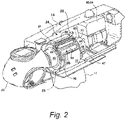
Fig. 2 is a cutaway perspective view of a conventional nacelle configuration with a superconducting generator; -
Fig. 3 is a side view of a generator configured with a cooling system in accordance with aspects of the present invention; -
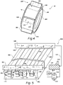
Fig. 4 is a perspective view of a rotating component of the cooling system with an embodiment of heat exchangers mounted around the periphery of the rotating armature; -
Fig. 5 is a view of an armature assembly configured with a cooling system in accordance with an embodiment of the invention; -
Fig. 6 is a view of an armature assembly configured with a cooling system in accordance with another embodiment of the invention; -
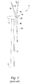
Fig. 7 is a diagram view of an arrangement of cooling circuits on a rotating generator component in accordance with an embodiment of the invention; -
Fig. 8 is a diagram view of an arrangement of cooling circuits on a rotating generator component in accordance with another embodiment of the invention; and -
Fig. 9 is a diagram view of an arrangement of cooling circuits on a rotating generator component in accordance with still a different embodiment of the invention. - Reference now will be made in detail to embodiments of the invention, one or more examples of which are illustrated in the drawings. Each example is provided by way of explanation of the invention, not limitation of the invention. In fact, it will be apparent to those skilled in the art that various modifications and variations can be made in the present invention without departing from the scope or spirit of the invention. For instance, features illustrated or described as part of one embodiment can be used with another embodiment to yield a still further embodiment. Thus, it is intended that the present invention covers such modifications and variations as come within the scope of the appended claims and their equivalents.
- Referring to the drawings,
Fig. 1 illustrates a perspective view of awind turbine 10. As mentioned, the present disclosure is directed to a generator that, although not limited to such use, is particularly well-suited for use in awind turbine 10. AlthoughFig. 1 depicts an "on-shore" (land-based)wind turbine 10 installation, it should be appreciated that the present invention is not limited to onshore wind turbines and is just as applicable to "off-shore" (water-based) wind turbine installations. - Although a superconducting generator is depicted in the figures and described herein, it should be understood that the invention is not limited to a superconducting generator and is applicable to any generator configuration having a rotating component that requires cooling. For example, a generator may be configured so that the armature assembly rotates around a stationary field assembly, wherein the armature assembly incorporates a cooling system in accordance with the invention. In an alternate generator configuration, the field assembly may rotate around a stationary armature assembly, wherein the field assembly incorporates the cooling system. In yet another alternate generator configuration, a rotating permanent magnet field may require cooling to allow use of less expensive permanent magnet materials.
- Referring again to
Fig. 1 , thewind turbine 10 includes atower 12 extending from asupport surface 14, anacelle 16 mounted on thetower 12, and arotor 18 coupled to thenacelle 16. Therotor 18 includes arotatable hub 20 and at least onerotor blade 22 coupled to and extending outwardly from thehub 20. For example, in the illustrated embodiment, therotor 18 includes threerotor blades 22. However, in an alternative embodiment, therotor 18 may include more or less than threerotor blades 22. Eachrotor blade 22 may be spaced about thehub 20 to facilitate rotating therotor 18 to enable kinetic energy to be transferred from the wind into usable mechanical energy, and subsequently, electrical energy. For instance, thehub 20 may be rotatably coupled to an electric generator (not shown) positioned within thenacelle 16 to permit electrical energy to be produced. -
Fig. 2 depicts asuperconducting generator 23 housed within thenacelle 16 and directly connected to therotor hub 20. Asupport tube 40 is connected directly to thehub 20 and supports the armature assembly 24 (includingarmature windings 27 and yoke orbody 30. Thus, thearmature assembly 24 is considered as the rotating component of thegenerator 23 with a rotating first electromagnetic component configuration in the form of a winding configuration 27 (with end turns 28) that rotate around thestationary field assembly 26 having a second electromagnetic component configuration , such as a superconductingfield winding assembly 26. - The superconducting
field winding assembly 26 includes superconducting coils 63, which may be a group of wires formed in a racetrack shape. Thecoils 63 are constrained to retain the racetrack shape. Eachsuperconducting coil 63 is supported in a recess/passage 83 in thecasing 71 and is cooled by a bath of helium to cryogenic temperatures or by some other method known with the engineering field of cryogenics. Thecasing 71 is supported in acryostat housing 56 which is fixed to abase tube 44. Amount 47 supports thebase tube 44 within thenacelle 16. The superconducting coils 63 are arranged side by side in an annular array extending around thecasing 71. For example, thirty-six (36) coils may form an annular array of field windings that serve as the stator field winding for the generator. The superconducting coils 63 may be each formed of (NbTi or other superconducting) wire wrapped in a helix around a racetrack form that may include cooling conduits for the helium. The superconducting field winding assembly includessuperconducting coil magnets 68, which are enclosed in thecasing 71 and receive cryogen through cooling recesses/passages 83. -
Cryogen re-condensors nacelle 16, provided that the cryogen cooling liquid in the re-condensors is at least partially elevated above the superconducting field windings to provide for gravity feed of the cryogen to the windings. Alternatively, the re-condensors 60, 64 may be mounted on top of the nacelle. -
Fig. 3 is a schematic diagram showing in cross-section the direct drive superconducting generator with the annular rotating armature assembly 24 ("armature 24") surrounding the stationary super-conductingfield winding assembly 26. Thearmature 24 is essentially an outer annular ring configuration (Fig. 4 ) that rotates around thefield winding assembly 26. Thearmature 24 includes theconductive windings 27, e.g., coils or bars, arranged longitudinally along the length of thearmature 24 and on an inside cylindrical surface of thearmature 24. The coils or bars 27 may be connected at their opposite ends to one another by conductive end turns 28. Theend turn connections 28 between the longitudinal coils or bars 27 are dependent on their number and arrangement, and the phases of electricity to be generated in thearmature windings 27. The inside cylindrical surface of thearmature windings 27 is separated by a narrow air gap, e.g., about 10-25 mm, from the outer surface of the stationaryfield winding assembly 26. - Thus, in a broad sense according to the invention, the
armature 24 may constitute the rotating component of a generator with a rotating electromagnetic component configuration (e.g.,windings 27 and end turns 28) while thestationary field assembly 26 may constitute a stationary component with a stationary electromagnetic component configuration (superconducting coils 63 and magnets 68 (Fig. 2 )). - The
armature 24 includes a cylindrical yoke or body 102 (referred to as "body" herein) that supports the coils/bars 27. In particular, the coils/bars 27 are contained in slots 110 (Fig. 5 ) defined betweenadjacent teeth 106 that extend radially from thebody 102, as is well-known in the art. Thebody 102 andteeth 106 may be a layered, laminated construction. The outer surface of thebody 30 is fixed to acylindrical housing 32 that rotates with thearmature 24. Thehousing 32 is fitted to acircular disc 34 that supports thehousing 32 andarmature 24. Thedisc 34 has a circular aperture at its center that is mounted to anannular bracket 36 to which is attached theannular base 38 of thehub 20 of the wind turbine. Thebracket 36 andbase 38 may be secured together by bolts arranged in a circular array around the bracket and base. Thedisc 34 may have openings orholes 35 for weight reduction. - The
bracket 36 is mounted on an end of the rotatingcylindrical support tube 40. A reinforcingring 37 is fixed to the inner corner between thebracket 36 andsupport tube 40. On an outside surface of thesupport tube 40, aslip ring assembly 41 is provided with contacts for each of the phases of AC power produced by the generator and a ground connection. Theslip ring 41 is electrically coupled to thewindings 27 of the rotatingarmature 24 and rotates with thesupport tube 40. A stationary connection, e.g. carbon brushes (not shown), conducts the electricity from theslip ring 41 andarmature 24 to wire conductors that extend to an electronic power converter and a step-up transformer before going down the tower and are coupled to a power utility grid, factory or other electrical power load. - A pair of
annular bearings 42 are arranged towards opposite ends of thesupport tube 40 and rotatably support thesupport tube 40 on thestationary base tube 44 that is attached to themount 47, which is supported by the floor of the nacelle. Aring bracket 46 may attach themount 47 to abracket 45 for the base tube. Bolts secure thebrackets - A
disc brake 48 grasps anannular lip 50 on an end of thehousing 32 and can be used to slow or stop the rotation of the blades, if the wind becomes excessive and the blades rotate too fast. Thin andlight weight gussets 52 extend from thecircular disc 34 to thesupport tube 40 and serve to reinforce thedisc 34. - The
base tube 44 supports a field windingsupport disc 54 on which is mounted the stationaryfield winding assembly 26. The disc may have cut-outs or holes 55 to reduce weight. Thedisc 54 is attached to an end of thecryostat housing 56 containing the superconducting coils 63 (Fig. 2 ) of thefield winding assembly 26. Thehousing 56 and its cooling components form a cryostat that cools the superconducting coils of the field winding. - The
cryostat housing 56 insulates the superconducting coils so that they may be cooled to near absolute zero, e.g., to 10 Kelvin (K) and preferably to 4K. To cool the windings, thecryostat housing 56 includesinsulated conduits 58 to receive liquid helium (He) or other similar cryogenic liquid (referred to as cryogen). A conventional two-stage re-condensor 60 mounted in an upper region of the nacelle, on top of the nacelle, or on top of the tower, and above the field windings to provide cryogen, e.g., liquid He, using a gravity feed. Thesecond re-condensor 64 provides a second cooling liquid, e.g., liquid nitrogen or neon, to an inner thermal shield of thecryostat housing 56. - Referring to
Figs. 3-5 in general, aheat exchange circuit 100 is arranged on the second rotating component (e.g., the armature 24) and includes one ormore coolant channels 112 defined longitudinally in theteeth 106 between opposite end faces 108 of eachtooth 106. Thus, thecoolant channels 112 extend through theteeth 106 essentially along the length of thebars 27 in thearmature 24. - The
coolant channels 112 conduct aliquid coolant 118 therethrough as depicted by the flow arrows inFig. 5 . Thecoolant 118 may be, for example, water or a mixture of water and glycol. The invention is not limited to any particular type or mixture of liquid coolant. - Referring to
Fig. 5 , theheat exchange circuit 100 includes one ormore pumps 114 that are carried by thearmature assembly 24 to rotate therewith. Onepump 114 may be sufficient, butmultiple pumps 114 configured in parallel may be desired for redundancy purposes. Thepumps 114 may be housed "under" (radially inward) of thebody 102/teeth 106 of the armature in a space at one of the longitudinal ends of the body that extends beyond a longitudinal end of thefield winding assembly 26. Thepumps 114 may be located in any space that allows for rotation with thearmature 24 without interfering with thefield winding assembly 26. - One or
more heat exchangers 116 are arranged on thehousing 32 of thearmature 24 so as to be rotatable with thehousing 32 andarmature 24. As depicted inFigs. 3 and4 , theheat exchangers 116 are arranged across thehousing 32 such that the faces of theheat exchanger 116 are transverse to a rotational direction of the housing 32 (e.g., at a non-zero angle relative to the rotational direction, which may be perpendicular). Thus, rotation of thearmature 24 andhousing 32 forces air flow through theheat exchanger 116, the flow rate of the air flow being a function of the rotational speed of thearmature 24. Various types ofheat exchanger 116 may be utilized. For example, theheat exchanger 116 may be passive liquid-to-air design that relies on air flow through the device to remove heat from theliquid coolant 118 that is circulated through tubes (which are attached to heat transfer fins). In an active design, a fan may be provided to force additional air through the heat exchanger 116 (in addition to air flow resulting from rotation of the armature 24). - As depicted in
Figs. 3 and5 , theheat exchange circuit 100 is preferably a closed-loop system wherein theheat exchanger 116, pump 114, andcoolant channels 112 are connected withsuitable conduit 132 such that theliquid coolant 118 is pumped in a closed loop through theheat exchanger 116 and thecoolant channels 112 to cool thewindings armature 24. - The
heat exchange circuit 100 may include auxiliary components as desired. For example,Figs. 5 and6 depict anoverflow tank 138 configured with theheat exchanger 116 and aheater 140, which may be desired in certain operating conditions to heat the coolant 118 (e.g., during a start-up of thegenerator 23 in a cold environment). - Referring particularly to
Fig. 4 , theheat exchangers 116 may be pivotably arranged on thehousing 32 so as to pivot from afunctional position 120 where theheat exchanger 116 extends radially outward from thehousing 32 to a stowedposition 122 wherein theheat exchanger 116 folds down against thehousing 32. Any manner of mechanical pivotal/hinge connection may be used to mount theheat exchanger 116 to thehousing 32 to achieve this desirable function. The inlet/outlet conduits 132 associated with theheat exchanger 116 can be disconnected in order to easily pivot/fold theheat exchanger 116 into the stowedposition 122. By pivoting all of theheat exchangers 116 to the stowed position, a morecompact armature 24 can be provided for shipping and installation at a wind turbine site, wherein theheat exchangers 116 are pre-mounted to thehousing 32 at the manufacturing plant. - The
heat exchange circuit 100 can have various configurations. For example, referring toFigs. 3-6 , thecircuit 100 may include aninlet manifold 124 and anoutlet manifold 126 that are in fluid communication with thecoolant channels 112 defined in theteeth 106. As depicted by the flow arrows inFig. 5 , theliquid coolant 118 is pumped into theinlet manifold 124 and then into theindividual coolant channels 112, through thecoolant channels 112, into theoutlet manifold 126, and back through theheat exchanger 116 in a closed-loop system. The inlet and outlet manifolds 124, 126 may be defined by any suitable channel, pipe, etc., with individual connections to therespective coolant channels 112. As depicted inFigs. 4 , theinlet manifold 124 may be provided on anend face 104 of thearmature 24 and theoutlet manifold 126 may be provided at theopposite end face 104. This arrangement is depicted schematically inFig. 5 . - In an alternative embodiment depicted schematically in
Fig. 6 , theinlet manifold 124 and theoutlet manifold 126 are arranged at a common one of the end faces 104 of thebody 102. The flow of thecoolant 118 reverses at the opposite end face via, for example, a tube/conduit 136 through aseparate coolant channel 112 to return to the outlet manifold 126 (e.g., the coolant makes at least two passes in each tooth). - The
coolant channels 112 may include one or more channels through eachtooth 106.Fig. 5 depictsvarious coolant channel 112 configurations. In the left-hand teeth 106 thecoolant channels 112 are defined "mid-tooth" through the length of thetooth 106, meaning that thecoolant channel 112 is not in direct fluid communication with theslot 110 in which thebars 27 are located. Thus, the heat exchange process is through the material of theteeth 106. -
Fig. 5 also depicts that a thermallyconductive tube 136 may run through thecoolant channel 112, wherein thistube 136 is connected to theinlet 124 andoutlet 126 manifolds. Thetubes 136 may be formed from any suitable thermally conductive material. Desirably, such material is also electrically insulating to a degree, such as stainless steel. - In
Fig. 6 , the thermallyconductive tube 136 runs through afirst coolant channel 112 in each tooth, reverses direction at theopposite end face 108 of thetooth 106, and runs back through adifferent coolant channel 112 in the tooth. - The third tooth 106 (from the left) in
Figs. 5-6 depictscoolant channels 112 that are open to theslots 110, with at least onesuch channel 112 assigned to eachbar 27. In this embodiment, theliquid coolant 118 may be in direct contact with thebar 27. Alternatively, a thermally conductive tube (as discussed above) may be disposed within each of thecoolant channels 112 such that these tubes are in direct contact with arespective bar 27. - In the last two teeth 106 (from the left) in
Figs. 5-6 , asingle coolant channel 112 is defined in the wall of thetooth 106 so as to be open to theslot 110. Thissingle coolant channel 112 has a length so as to be in fluid communication with bothbars 27 contained in theslot 110. A thermally conductive tube (as discussed above) may be disposed within thesingle coolant channel 112 such that this tube is in direct contact with both of thebars 27. - It should be appreciated that although two
coolant channels 112 are depicted in the figures with eachtooth 106, any number of channels (as well as the shape of the channels) are feasible and can define a multi-pass system within eachtooth 106 for theliquid coolant 118. Suitable tubes/conduits can be provided at the end faces 108 of theteeth 106 for reversing flow through themultiple coolant channels 112. - As mentioned, the
heat exchange circuit 100 may include a plurality of thepumps 114 and a plurality of theheat exchangers 116, with each of theheat exchangers 116 pivotably mounted on thehousing 32 and pivotal between thefunctional position 120 extending radially outward from thehousing 32 and the stowedposition 122 folded down against thehousing 32. The plurality ofpumps 114 andheat exchangers 116 can be variously configured within theheat exchange circuit 100. For example,Fig. 9 depicts an embodiment wherein all of theheat exchangers 116 and thepumps 114 are in a parallel configuration with all of the coolant channels. In this arrangement, a single one of thepumps 114 and a single one of theheat exchangers 116 can service all of the coolant channels if need be. - In an alternate embodiment depicted in
Fig. 7 , the heat exchange circuit is divided into a plurality ofsub-circuits 130, with each sub-circuit 130 having at least oneheat exchanger 116 and at least onepump 114 configured in a closed-loop system with asubset 142 of thecoolant channels 112 assigned to the sub-circuit 130. Each sub-circuit 130 may include itsown inlet manifold 124 andoutlet manifold 126, wherein theliquid coolant 118 is pumped from theinlet manifold 124, through thecoolant channels 112 assigned to the sub-circuit 130, and into theoutlet manifold 126. - In the embodiment of
Fig. 8 , each sub-circuit 130 includes at least twoheat exchangers 116 and at least twopumps 114 to service thecoolant channels 112 assigned to the sub-circuit 130. - Also mentioned, the present invention also encompasses a wind turbine 10 (onshore or offshore installation) that utilizes a generator (conventional or superconducting) to generate and supply electricity to a grid, wherein the generator is in accordance with any of the embodiments described above.
- Aspects and details of the invention are provided by the subject matter of the following clauses:
- Clause 1: A generator, comprising:
- a first stationary component carrying a first winding configuration;
- a second rotating component carrying a second winding configuration, the second rotating component arranged to rotate around the first stationary component;
- the second rotating component comprising:
- a body portion;
- a plurality of teeth spaced around and extending radially from the body portion, the body portion and the teeth extending longitudinally between opposite end faces;
- a slot defined between adjacent ones of the teeth, the second winding configuration arranged in the slots;
- a housing arranged around and rotatable with the body portion;
- a heat exchange circuit arranged on the second rotating component, comprising:
- a coolant channel defined longitudinally in the teeth and extending between the opposite end faces of the teeth;
- a pump carried by the second rotating component;
- a heat exchanger arranged on the housing so as to be rotatable with the housing, the heat exchanger arranged across the housing transverse to a rotational direction of the housing such that rotation of the housing forces air flow through the heat exchanger;
- a liquid coolant; and
- wherein the heat exchanger, the pump, and the coolant channels are in a closed-loop configuration such that the liquid coolant is pumped through the heat exchanger and the coolant channels to cool the second winding configuration.
- Clause 2: The generator as in clause 1, wherein the generator is a superconducting generator, the first stationary component comprising a superconducting field winding configuration and the second rotating component comprising an armature assembly with the second winding configuration comprising coils or bars arranged in the slots.
- Clause 3: The generator as in clause 1, wherein the heat exchanger is pivotably arranged on the housing and is pivotal between a functional position extending radially outward from the housing and a stowed position folded down against the housing.
- Clause 4: The generator as in clause 1, wherein the heat exchange circuit comprises an inlet manifold and an outlet manifold configured, wherein the liquid coolant is pumped from the inlet manifold, through the coolant channels, and into the outlet manifold.
- Clause 5: The generator as in clause 4, wherein the heat exchange circuit comprises tubes disposed through the coolant channels to conduct the liquid coolant therethrough, the tubes connected to the inlet manifold and the outlet manifold.
- Clause 6: The generator as in clause 5, wherein the inlet manifold and the outlet manifold are each arranged at one of the opposite end faces of the body.
- Clause 7: The generator as in clause 5, wherein the inlet manifold and the outlet manifold are arranged at a common one of the opposite end faces of the body, the tubes disposed in a first one of the coolant channels in the teeth, reversing direction at the opposite end face of the body, and running through a second one of the coolant channels in the same tooth.
- Clause 8: The generator as in clause 1, wherein the heat exchange circuit comprises a plurality of the pumps and a plurality of the heat exchangers, each of the heat exchangers pivotably arranged on the housing and pivotal between a functional position extending radially outward from the housing and a stowed position folded down against the housing.
- Clause 9: The generator as in clause 8, wherein the heat exchange circuit comprises all of the heat exchangers and the pumps in a parallel configuration with all of the coolant channels.
- Clause 10: The generator as in clause 8, wherein the heat exchange circuit comprises a plurality of sub-circuits, each of the sub-circuits configured in a closed-loop with a subset of the coolant channels and comprising at least one of the heat exchangers and at least one of the pumps.
- Clause 11: The generator as in
clause 10, wherein each of the sub-circuits comprises a plurality of the heat exchangers and a plurality of the pumps. - Clause 12: The generator as in
clause 10, wherein each of the sub-circuits comprises an inlet manifold configured at one of the end faces of the body and an outlet manifold configured at the opposite end face of the body, wherein the liquid coolant is pumped from the inlet manifold, through the coolant channels assigned to the sub-circuit, and into the outlet manifold. - Clause 13: A wind turbine, comprising:
- a superconducting generator, comprising:
- a stationary field assembly with a superconducting field winding configuration;
- a rotating armature assembly that rotates relative to the field assembly and comprises a body portion and a plurality of teeth spaced around and extending radially from the body portion, the body portion and the teeth extending longitudinally between opposite end faces and defining slots between the teeth; and
- an armature winding configuration comprising coils or bars arranged in the slots;
- a housing arranged around and rotatable with the body portion;
- a heat exchange circuit arranged on the rotating armature assembly, the heat exchange circuit, comprising:
- at least one coolant channel defined longitudinally in each of the teeth between the opposite end faces of the teeth;
- a pump carried by the rotating armature assembly;
- a heat exchanger arranged on the housing so as to be rotatable with the housing, the heat exchanger arranged across the housing transverse to a rotational direction of the housing such that rotation of the armature assembly forces air flow through the heat exchanger;
- a liquid coolant; and
- wherein the heat exchanger, the pump, and the coolant channels are in a closed-loop configuration such that the liquid coolant is pumped through the heat exchanger and the coolant channels to cool the armature winding.
- a superconducting generator, comprising:
- Clause 14: The wind turbine as in clause 13, wherein the heat exchange circuit comprises an inlet manifold and an outlet manifold configured, wherein the liquid coolant is pumped from the inlet manifold, through the coolant channels, and into the outlet manifold.
- Clause 15: The wind turbine as in
clause 14, wherein the heat exchange circuit comprises tubes disposed through the coolant channels to conduct the liquid coolant therethrough, the tubes connected to the inlet manifold and the outlet manifold. - Clause 16: The wind turbine as in
clause 14, wherein the inlet manifold and the outlet manifold are arranged at a common one of the opposite end faces of the body, the tubes disposed in a first one of the coolant channels in the teeth, reversing direction at the opposite end face of the body, and running through a second one of the coolant channels in the same tooth. - Clause 17: The wind turbine as in clause 13, wherein the heat exchange circuit comprises a plurality of the pumps and a plurality of the heat exchangers, each of the heat exchangers pivotably arranged on the housing and pivotal between a functional position extending radially outward from the housing and a stowed position folded down against the housing.
- Clause 18: The wind turbine as in clause 17, wherein the heat exchange circuit comprises a plurality of sub-circuits, each of the sub-circuits configured in a closed-loop with a subset of the coolant channels and comprising at least one of the heat exchangers and at least one of the pumps.
- Clause 19: The wind turbine as in
clause 18, wherein each of the sub-circuits comprises an inlet manifold and an outlet manifold, wherein the liquid coolant is pumped from the inlet manifold, through the coolant channels assigned to the sub-circuit, and into the outlet manifold. - Clause 21: Wind turbine comprising the generator as described herein.
- Clause 22: Wind turbine comprising the generator as specified in any of clauses 1 to 12.
- This written description uses examples to disclose the invention, including the best mode, and also to enable any person skilled in the art to practice the invention, including making and using any devices or systems and performing any incorporated methods. The patentable scope of the invention is defined by the claims, and may include other examples that occur to those skilled in the art. Such other examples are intended to be within the scope of the claims if they include structural elements that do not differ from the literal language of the claims, or if they include equivalent structural elements with insubstantial differences from the literal languages of the claims.
Claims (15)
- A generator, comprising:a first stationary component carrying a first electromagnetic component configuration;a second rotating component carrying a second electromagnetic component configuration, the second rotating component arranged to rotate relative to the first stationary component;the second rotating component comprising:
a body portion;a plurality of teeth spaced around and extending radially from the body portion, the body portion and the teeth extending longitudinally between opposite end faces;a slot defined between adjacent ones of the teeth, the second electromagnetic component configuration arranged in the slots;a housing arranged around and rotatable with the body portion;a heat exchange circuit arranged on the second rotating component, comprising:a coolant channel defined longitudinally in the teeth and extending between the opposite end faces of the teeth;
a pump carried by the second rotating component;a heat exchanger arranged on the housing so as to be rotatable with the housing, the heat exchanger arranged across the housing transverse to a rotational direction of the housing such that rotation of the housing forces air flow through the heat exchanger;
a liquid coolant; andwherein the heat exchanger, the pump, and the coolant channels are in a closed-loop configuration such that the liquid coolant is pumped through the heat exchanger and the coolant channels to cool the second winding configuration. - The generator as in claim 1, wherein the generator is a superconducting generator, the first stationary component comprising a superconducting field winding configuration and the second rotating component comprising an armature assembly with the second electromagnetic component configuration comprising coils or bars arranged in the slots.
- The generator as in any of the preceding claims, wherein the heat exchanger is pivotably arranged on the housing and is pivotal between a functional position extending radially outward from the housing and a stowed position folded down against the housing.
- The generator as in any of the preceding claims, wherein the heat exchange circuit comprises an inlet manifold and an outlet manifold configured, wherein the liquid coolant is pumped from the inlet manifold, through the coolant channels, and into the outlet manifold.
- The generator as in any of the preceding claims, wherein the heat exchange circuit comprises tubes disposed through the coolant channels to conduct the liquid coolant therethrough, the tubes connected to the inlet manifold and the outlet manifold.
- The generator as in any of the preceding claims, wherein the inlet manifold and the outlet manifold are each arranged at one of the opposite end faces of the body.
- The generator as in any of the preceding claims, wherein the inlet manifold and the outlet manifold are arranged at a common one of the opposite end faces of the body, the tubes disposed in a first one of the coolant channels in the teeth, reversing direction at the opposite end face of the body, and running through a second one of the coolant channels in the same tooth.
- The generator as in any of the preceding claims, wherein the heat exchange circuit comprises a plurality of the pumps and a plurality of the heat exchangers, each of the heat exchangers pivotably arranged on the housing and pivotal between a functional position extending radially outward from the housing and a stowed position folded down against the housing.
- The generator as in any of the preceding claims, wherein the heat exchange circuit comprises all of the heat exchangers and the pumps in a parallel configuration with all of the coolant channels.
- The generator as in any of the preceding claims, wherein the heat exchange circuit comprises a plurality of sub-circuits, each of the sub-circuits configured in a closed-loop with a subset of the coolant channels and comprising at least one of the heat exchangers and at least one of the pumps.
- The generator as in any of the preceding claims, wherein each of the sub-circuits comprises a plurality of the heat exchangers and a plurality of the pumps.
- The generator as in any of the preceding claims, wherein each of the sub-circuits comprises an inlet manifold configured at one of the end faces of the body and an outlet manifold configured at the opposite end face of the body, wherein the liquid coolant is pumped from the inlet manifold, through the coolant channels assigned to the sub-circuit, and into the outlet manifold.
- A wind turbine, comprising:a superconducting generator, comprising:a stationary field assembly with a superconducting field winding configuration;a rotating armature assembly that rotates relative to the field assembly and comprises a body portion and a plurality of teeth spaced around and extending radially from the body portion, the body portion and the teeth extending longitudinally between opposite end faces and defining slots between the teeth; andan armature winding configuration comprising coils or bars arranged in the slots;a housing arranged around and rotatable with the body portion;a heat exchange circuit arranged on the rotating armature assembly, the heat exchange circuit, comprising:at least one coolant channel defined longitudinally in each of the teeth between the opposite end faces of the teeth;
a pump carried by the rotating armature assembly;a heat exchanger arranged on the housing so as to be rotatable with the housing, the heat exchanger arranged across the housing transverse to a rotational direction of the housing such that rotation of the armature assembly forces air flow through the heat exchanger;
a liquid coolant; andwherein the heat exchanger, the pump, and the coolant channels are in a closed-loop configuration such that the liquid coolant is pumped through the heat exchanger and the coolant channels to cool the armature winding. - The wind turbine as in claim 13, wherein the heat exchange circuit comprises an inlet manifold and an outlet manifold configured, wherein the liquid coolant is pumped from the inlet manifold, through the coolant channels, and into the outlet manifold.
- The wind turbine as in claims 13-14, wherein the heat exchange circuit comprises tubes disposed through the coolant channels to conduct the liquid coolant therethrough, the tubes connected to the inlet manifold and the outlet manifold.
Applications Claiming Priority (1)
| Application Number | Priority Date | Filing Date | Title |
|---|---|---|---|
| US17/122,210 US11387699B2 (en) | 2020-12-15 | 2020-12-15 | Rotating cooling system for wind turbine generator |
Publications (2)
| Publication Number | Publication Date |
|---|---|
| EP4016805A1 true EP4016805A1 (en) | 2022-06-22 |
| EP4016805B1 EP4016805B1 (en) | 2025-09-10 |
Family
ID=78820623
Family Applications (1)
| Application Number | Title | Priority Date | Filing Date |
|---|---|---|---|
| EP21211718.8A Active EP4016805B1 (en) | 2020-12-15 | 2021-12-01 | Rotating cooling system for wind turbine generator |
Country Status (5)
| Country | Link |
|---|---|
| US (1) | US11387699B2 (en) |
| EP (1) | EP4016805B1 (en) |
| JP (1) | JP2022094935A (en) |
| KR (1) | KR20220085729A (en) |
| CN (1) | CN114640212A (en) |
Cited By (1)
| Publication number | Priority date | Publication date | Assignee | Title |
|---|---|---|---|---|
| WO2024019737A1 (en) * | 2022-07-22 | 2024-01-25 | General Electric Company | Fiber reinforced composite armature winding support structure for a superconducting machine |
Families Citing this family (3)
| Publication number | Priority date | Publication date | Assignee | Title |
|---|---|---|---|---|
| EP4559073A1 (en) * | 2022-08-29 | 2025-05-28 | General Electric Renovables España, S.L. | Cooling system for a superconducting generator |
| EP4344031A1 (en) * | 2022-09-26 | 2024-03-27 | Wobben Properties GmbH | Generator for a wind turbine generating electric energy from kinetic energy, wind turbine |
| CN118137746B (en) * | 2024-05-10 | 2024-07-19 | 江苏赛夫特防爆电气有限公司 | Cooler for wind driven generator |
Citations (4)
| Publication number | Priority date | Publication date | Assignee | Title |
|---|---|---|---|---|
| EP0461905A2 (en) * | 1990-06-15 | 1991-12-18 | General Electric Company | Liquid cooling the rotor of a electrical machine |
| EP1959548A1 (en) * | 2007-02-15 | 2008-08-20 | General Electric Company | Method and apparatus for a superconducting generator driven by wind turbine |
| US7928616B2 (en) | 2008-05-19 | 2011-04-19 | General Electric Company | Systems and apparatus involving toothed armatures in superconducting machines |
| EP2636131B1 (en) * | 2010-11-04 | 2020-02-19 | Wobben Properties GmbH | Wind energy installation having a synchronous generator, and slowly rotating synchronous generator |
Family Cites Families (18)
| Publication number | Priority date | Publication date | Assignee | Title |
|---|---|---|---|---|
| IT1308475B1 (en) | 1999-05-07 | 2001-12-17 | Gate Spa | FAN MOTOR, IN PARTICULAR FOR A HEAT EXCHANGER OF A VEHICLE |
| US7345376B2 (en) | 2004-11-30 | 2008-03-18 | Distributed Energy Systems Corporation | Passively cooled direct drive wind turbine |
| US7443066B2 (en) | 2005-07-29 | 2008-10-28 | General Electric Company | Methods and apparatus for cooling wind turbine generators |
| US20090224550A1 (en) | 2008-03-06 | 2009-09-10 | General Electric Company | Systems involving superconducting direct drive generators for wind power applications |
| US8115352B2 (en) | 2009-03-17 | 2012-02-14 | General Electric Company | Dynamoelectric machine coil spacerblock having flow deflecting channel in coil facing surface thereof |
| US7893576B2 (en) | 2009-05-05 | 2011-02-22 | General Electric Company | Generator coil cooling baffles |
| US7843080B2 (en) | 2009-05-11 | 2010-11-30 | General Electric Company | Cooling system and wind turbine incorporating same |
| US8525376B2 (en) | 2010-10-01 | 2013-09-03 | General Electric Company | Dynamoelectric machine coil spaceblock having flow deflecting structure in coil facing surface thereof |
| US8338979B2 (en) * | 2011-06-30 | 2012-12-25 | General Electric Company | Method and apparatus for a superconducting direct current generator driven by a wind turbine |
| US9046081B2 (en) * | 2011-12-07 | 2015-06-02 | Envision Energy (Denmark) Aps | Wind turbine with sealed off stator chamber |
| DK201270179A (en) * | 2012-04-11 | 2013-10-11 | Envision Energy Denmark Aps | Wind turbine with improved cooling |
| US10277086B2 (en) | 2014-11-26 | 2019-04-30 | Siemens Energy, Inc. | Thermo pump-cooled generator end windings with internal cooling passages |
| KR101755822B1 (en) | 2015-08-11 | 2017-07-07 | 두산중공업 주식회사 | Rotor assembly having vane structure |
| KR101757051B1 (en) | 2015-08-24 | 2017-07-11 | 두산중공업 주식회사 | Rotor assembly having improved cooling path |
| KR101783098B1 (en) | 2015-09-01 | 2017-09-28 | 두산중공업 주식회사 | Rotor assembly having cooling path |
| KR101758989B1 (en) | 2015-09-02 | 2017-07-17 | 두산중공업 주식회사 | rotor assembly for generator |
| KR101756535B1 (en) | 2015-09-09 | 2017-07-10 | 두산중공업 주식회사 | Rotor assembly having improved cooling path |
| US20170288504A1 (en) | 2016-04-01 | 2017-10-05 | Prestolite Electric, Inc. | Systems and methods for cooling electronics and a rear end of stator windings in an alternator |
-
2020
- 2020-12-15 US US17/122,210 patent/US11387699B2/en active Active
-
2021
- 2021-12-01 EP EP21211718.8A patent/EP4016805B1/en active Active
- 2021-12-02 JP JP2021195860A patent/JP2022094935A/en active Pending
- 2021-12-13 KR KR1020210177960A patent/KR20220085729A/en not_active Ceased
- 2021-12-15 CN CN202111535897.4A patent/CN114640212A/en active Pending
Patent Citations (4)
| Publication number | Priority date | Publication date | Assignee | Title |
|---|---|---|---|---|
| EP0461905A2 (en) * | 1990-06-15 | 1991-12-18 | General Electric Company | Liquid cooling the rotor of a electrical machine |
| EP1959548A1 (en) * | 2007-02-15 | 2008-08-20 | General Electric Company | Method and apparatus for a superconducting generator driven by wind turbine |
| US7928616B2 (en) | 2008-05-19 | 2011-04-19 | General Electric Company | Systems and apparatus involving toothed armatures in superconducting machines |
| EP2636131B1 (en) * | 2010-11-04 | 2020-02-19 | Wobben Properties GmbH | Wind energy installation having a synchronous generator, and slowly rotating synchronous generator |
Cited By (1)
| Publication number | Priority date | Publication date | Assignee | Title |
|---|---|---|---|---|
| WO2024019737A1 (en) * | 2022-07-22 | 2024-01-25 | General Electric Company | Fiber reinforced composite armature winding support structure for a superconducting machine |
Also Published As
| Publication number | Publication date |
|---|---|
| US11387699B2 (en) | 2022-07-12 |
| US20220190663A1 (en) | 2022-06-16 |
| CN114640212A (en) | 2022-06-17 |
| EP4016805B1 (en) | 2025-09-10 |
| JP2022094935A (en) | 2022-06-27 |
| KR20220085729A (en) | 2022-06-22 |
Similar Documents
| Publication | Publication Date | Title |
|---|---|---|
| EP4016805B1 (en) | Rotating cooling system for wind turbine generator | |
| CN101247070B (en) | Method and apparatus for a superconducting generator driven by wind turbine | |
| US20130270937A1 (en) | Wind turbine with improved cooling | |
| US20100259117A1 (en) | Dual armature motor/generator with flux linkage between dual armatures and a superconducting field coil | |
| CN105917560B (en) | Superconducting generator and motor and the method using the motor | |
| WO2007116263A1 (en) | Electric generator for wind and water turbines | |
| KR102927962B1 (en) | Cooling of electrical machines | |
| CN101162859A (en) | A doubly-fed asynchronous wind generator above megawatt level | |
| EP3186505B1 (en) | Synchronous superconductive rotary machine having a slidable pole assembly and methods thereof | |
| CN108370211A (en) | Synchronization superconducting rotating machine with the configuration of continuous pole | |
| EP1691469A2 (en) | Coolant fluid transfer device and method for conveying coolant fluid to a rotating member | |
| US10224799B2 (en) | Cooling assembly for electrical machines and methods of assembling the same | |
| KR102371278B1 (en) | Vertical axis type wind turbine equipped with high-temperature superconducting generator with batch impregnation cooling structure using cryogen | |
| US20220021275A1 (en) | Cooling of electrical machines | |
| WO2024043876A1 (en) | Gas tank cooling for a thermal shield of a superconducting machine | |
| US20260066744A1 (en) | Cooling system for a superconducting generator | |
| WO2024144764A1 (en) | Forced flow cooling system for a superconducting machine | |
| CN112514219A (en) | Generator with superconducting coil winding | |
| CN119585984A (en) | Fiber-reinforced composite armature winding support structures for superconducting machines |
Legal Events
| Date | Code | Title | Description |
|---|---|---|---|
| PUAI | Public reference made under article 153(3) epc to a published international application that has entered the european phase |
Free format text: ORIGINAL CODE: 0009012 |
|
| STAA | Information on the status of an ep patent application or granted ep patent |
Free format text: STATUS: THE APPLICATION HAS BEEN PUBLISHED |
|
| AK | Designated contracting states |
Kind code of ref document: A1 Designated state(s): AL AT BE BG CH CY CZ DE DK EE ES FI FR GB GR HR HU IE IS IT LI LT LU LV MC MK MT NL NO PL PT RO RS SE SI SK SM TR |
|
| STAA | Information on the status of an ep patent application or granted ep patent |
Free format text: STATUS: REQUEST FOR EXAMINATION WAS MADE |
|
| 17P | Request for examination filed |
Effective date: 20221130 |
|
| RBV | Designated contracting states (corrected) |
Designated state(s): AL AT BE BG CH CY CZ DE DK EE ES FI FR GB GR HR HU IE IS IT LI LT LU LV MC MK MT NL NO PL PT RO RS SE SI SK SM TR |
|
| P01 | Opt-out of the competence of the unified patent court (upc) registered |
Effective date: 20230529 |
|
| STAA | Information on the status of an ep patent application or granted ep patent |
Free format text: STATUS: EXAMINATION IS IN PROGRESS |
|
| 17Q | First examination report despatched |
Effective date: 20230718 |
|
| GRAP | Despatch of communication of intention to grant a patent |
Free format text: ORIGINAL CODE: EPIDOSNIGR1 |
|
| STAA | Information on the status of an ep patent application or granted ep patent |
Free format text: STATUS: GRANT OF PATENT IS INTENDED |
|
| RIC1 | Information provided on ipc code assigned before grant |
Ipc: H02K 55/02 20060101ALN20250123BHEP Ipc: H02K 9/19 20060101ALI20250123BHEP Ipc: H02K 7/18 20060101ALI20250123BHEP Ipc: H02K 1/32 20060101AFI20250123BHEP |
|
| INTG | Intention to grant announced |
Effective date: 20250210 |
|
| GRAJ | Information related to disapproval of communication of intention to grant by the applicant or resumption of examination proceedings by the epo deleted |
Free format text: ORIGINAL CODE: EPIDOSDIGR1 |
|
| STAA | Information on the status of an ep patent application or granted ep patent |
Free format text: STATUS: EXAMINATION IS IN PROGRESS |
|
| GRAP | Despatch of communication of intention to grant a patent |
Free format text: ORIGINAL CODE: EPIDOSNIGR1 |
|
| STAA | Information on the status of an ep patent application or granted ep patent |
Free format text: STATUS: GRANT OF PATENT IS INTENDED |
|
| INTC | Intention to grant announced (deleted) | ||
| RIC1 | Information provided on ipc code assigned before grant |
Ipc: H02K 1/32 20060101AFI20250625BHEP Ipc: H02K 7/18 20060101ALI20250625BHEP Ipc: H02K 9/19 20060101ALI20250625BHEP Ipc: H02K 55/02 20060101ALN20250625BHEP |
|
| GRAS | Grant fee paid |
Free format text: ORIGINAL CODE: EPIDOSNIGR3 |
|
| INTG | Intention to grant announced |
Effective date: 20250702 |
|
| RIN1 | Information on inventor provided before grant (corrected) |
Inventor name: SCHURING, ROELOF WILLEM Inventor name: OSUSKY, LANA MARIA Inventor name: CROSS, ANDREW THOMAS Inventor name: TORREY, DAVID ALLAN |
|
| GRAA | (expected) grant |
Free format text: ORIGINAL CODE: 0009210 |
|
| STAA | Information on the status of an ep patent application or granted ep patent |
Free format text: STATUS: THE PATENT HAS BEEN GRANTED |
|
| AK | Designated contracting states |
Kind code of ref document: B1 Designated state(s): AL AT BE BG CH CY CZ DE DK EE ES FI FR GB GR HR HU IE IS IT LI LT LU LV MC MK MT NL NO PL PT RO RS SE SI SK SM TR |
|
| REG | Reference to a national code |
Ref country code: GB Ref legal event code: FG4D |
|
| REG | Reference to a national code |
Ref country code: CH Ref legal event code: EP |
|
| REG | Reference to a national code |
Ref country code: DE Ref legal event code: R096 Ref document number: 602021038198 Country of ref document: DE |
|
| REG | Reference to a national code |
Ref country code: IE Ref legal event code: FG4D |
|
| PG25 | Lapsed in a contracting state [announced via postgrant information from national office to epo] |
Ref country code: NO Free format text: LAPSE BECAUSE OF FAILURE TO SUBMIT A TRANSLATION OF THE DESCRIPTION OR TO PAY THE FEE WITHIN THE PRESCRIBED TIME-LIMIT Effective date: 20251210 |
|
| REG | Reference to a national code |
Ref country code: LT Ref legal event code: MG9D |
|
| PGFP | Annual fee paid to national office [announced via postgrant information from national office to epo] |
Ref country code: AT Payment date: 20260113 Year of fee payment: 5 |
|
| PG25 | Lapsed in a contracting state [announced via postgrant information from national office to epo] |
Ref country code: FI Free format text: LAPSE BECAUSE OF FAILURE TO SUBMIT A TRANSLATION OF THE DESCRIPTION OR TO PAY THE FEE WITHIN THE PRESCRIBED TIME-LIMIT Effective date: 20250910 |
|
| REG | Reference to a national code |
Ref country code: NL Ref legal event code: MP Effective date: 20250910 |
|
| PG25 | Lapsed in a contracting state [announced via postgrant information from national office to epo] |
Ref country code: HR Free format text: LAPSE BECAUSE OF FAILURE TO SUBMIT A TRANSLATION OF THE DESCRIPTION OR TO PAY THE FEE WITHIN THE PRESCRIBED TIME-LIMIT Effective date: 20250910 |
|
| PG25 | Lapsed in a contracting state [announced via postgrant information from national office to epo] |
Ref country code: GR Free format text: LAPSE BECAUSE OF FAILURE TO SUBMIT A TRANSLATION OF THE DESCRIPTION OR TO PAY THE FEE WITHIN THE PRESCRIBED TIME-LIMIT Effective date: 20251211 |
|
| PG25 | Lapsed in a contracting state [announced via postgrant information from national office to epo] |
Ref country code: SE Free format text: LAPSE BECAUSE OF FAILURE TO SUBMIT A TRANSLATION OF THE DESCRIPTION OR TO PAY THE FEE WITHIN THE PRESCRIBED TIME-LIMIT Effective date: 20250910 |
|
| PG25 | Lapsed in a contracting state [announced via postgrant information from national office to epo] |
Ref country code: LV Free format text: LAPSE BECAUSE OF FAILURE TO SUBMIT A TRANSLATION OF THE DESCRIPTION OR TO PAY THE FEE WITHIN THE PRESCRIBED TIME-LIMIT Effective date: 20250910 |
|
| PG25 | Lapsed in a contracting state [announced via postgrant information from national office to epo] |
Ref country code: BG Free format text: LAPSE BECAUSE OF FAILURE TO SUBMIT A TRANSLATION OF THE DESCRIPTION OR TO PAY THE FEE WITHIN THE PRESCRIBED TIME-LIMIT Effective date: 20250910 Ref country code: PL Free format text: LAPSE BECAUSE OF FAILURE TO SUBMIT A TRANSLATION OF THE DESCRIPTION OR TO PAY THE FEE WITHIN THE PRESCRIBED TIME-LIMIT Effective date: 20250910 |
|
| PG25 | Lapsed in a contracting state [announced via postgrant information from national office to epo] |
Ref country code: RS Free format text: LAPSE BECAUSE OF FAILURE TO SUBMIT A TRANSLATION OF THE DESCRIPTION OR TO PAY THE FEE WITHIN THE PRESCRIBED TIME-LIMIT Effective date: 20251210 |
|
| PG25 | Lapsed in a contracting state [announced via postgrant information from national office to epo] |
Ref country code: ES Free format text: LAPSE BECAUSE OF FAILURE TO SUBMIT A TRANSLATION OF THE DESCRIPTION OR TO PAY THE FEE WITHIN THE PRESCRIBED TIME-LIMIT Effective date: 20250910 |
|
| REG | Reference to a national code |
Ref country code: AT Ref legal event code: MK05 Ref document number: 1836957 Country of ref document: AT Kind code of ref document: T Effective date: 20250910 |
|
| PG25 | Lapsed in a contracting state [announced via postgrant information from national office to epo] |
Ref country code: NL Free format text: LAPSE BECAUSE OF FAILURE TO SUBMIT A TRANSLATION OF THE DESCRIPTION OR TO PAY THE FEE WITHIN THE PRESCRIBED TIME-LIMIT Effective date: 20250910 |
|
| REG | Reference to a national code |
Ref country code: CH Ref legal event code: W10 Free format text: ST27 STATUS EVENT CODE: U-0-0-W10-W00 (AS PROVIDED BY THE NATIONAL OFFICE) Effective date: 20260218 |
|
| RAP4 | Party data changed (patent owner data changed or rights of a patent transferred) |
Owner name: GE VERNOVA RENOVABLES ESPANA, S.L. |
|
| REG | Reference to a national code |
Ref country code: CH Ref legal event code: W10 Free format text: ST27 STATUS EVENT CODE: U-0-0-W10-W00 (AS PROVIDED BY THE NATIONAL OFFICE) Effective date: 20260325 |
|
| PG25 | Lapsed in a contracting state [announced via postgrant information from national office to epo] |
Ref country code: SM Free format text: LAPSE BECAUSE OF FAILURE TO SUBMIT A TRANSLATION OF THE DESCRIPTION OR TO PAY THE FEE WITHIN THE PRESCRIBED TIME-LIMIT Effective date: 20250910 |
|
| PG25 | Lapsed in a contracting state [announced via postgrant information from national office to epo] |
Ref country code: AT Free format text: LAPSE BECAUSE OF FAILURE TO SUBMIT A TRANSLATION OF THE DESCRIPTION OR TO PAY THE FEE WITHIN THE PRESCRIBED TIME-LIMIT Effective date: 20250910 |
|
| PG25 | Lapsed in a contracting state [announced via postgrant information from national office to epo] |
Ref country code: RO Free format text: LAPSE BECAUSE OF FAILURE TO SUBMIT A TRANSLATION OF THE DESCRIPTION OR TO PAY THE FEE WITHIN THE PRESCRIBED TIME-LIMIT Effective date: 20250910 Ref country code: IT Free format text: LAPSE BECAUSE OF FAILURE TO SUBMIT A TRANSLATION OF THE DESCRIPTION OR TO PAY THE FEE WITHIN THE PRESCRIBED TIME-LIMIT Effective date: 20250910 |
|
| PG25 | Lapsed in a contracting state [announced via postgrant information from national office to epo] |
Ref country code: IS Free format text: LAPSE BECAUSE OF FAILURE TO SUBMIT A TRANSLATION OF THE DESCRIPTION OR TO PAY THE FEE WITHIN THE PRESCRIBED TIME-LIMIT Effective date: 20260110 |
|
| RAP4 | Party data changed (patent owner data changed or rights of a patent transferred) |
Owner name: GE VERNOVA RENOVABLES ESPANA, S.L. |
|
| PG25 | Lapsed in a contracting state [announced via postgrant information from national office to epo] |
Ref country code: CZ Free format text: LAPSE BECAUSE OF FAILURE TO SUBMIT A TRANSLATION OF THE DESCRIPTION OR TO PAY THE FEE WITHIN THE PRESCRIBED TIME-LIMIT Effective date: 20250910 Ref country code: PT Free format text: LAPSE BECAUSE OF FAILURE TO SUBMIT A TRANSLATION OF THE DESCRIPTION OR TO PAY THE FEE WITHIN THE PRESCRIBED TIME-LIMIT Effective date: 20260112 |
|
| PG25 | Lapsed in a contracting state [announced via postgrant information from national office to epo] |
Ref country code: EE Free format text: LAPSE BECAUSE OF FAILURE TO SUBMIT A TRANSLATION OF THE DESCRIPTION OR TO PAY THE FEE WITHIN THE PRESCRIBED TIME-LIMIT Effective date: 20250910 Ref country code: SK Free format text: LAPSE BECAUSE OF FAILURE TO SUBMIT A TRANSLATION OF THE DESCRIPTION OR TO PAY THE FEE WITHIN THE PRESCRIBED TIME-LIMIT Effective date: 20250910 |