EP4016774B1 - Electric power supply module for ceilings, walls made of plasterboard and the like - Google Patents
Electric power supply module for ceilings, walls made of plasterboard and the like Download PDFInfo
- Publication number
- EP4016774B1 EP4016774B1 EP21212327.7A EP21212327A EP4016774B1 EP 4016774 B1 EP4016774 B1 EP 4016774B1 EP 21212327 A EP21212327 A EP 21212327A EP 4016774 B1 EP4016774 B1 EP 4016774B1
- Authority
- EP
- European Patent Office
- Prior art keywords
- profiled element
- panels
- module according
- module
- main body
- Prior art date
- Legal status (The legal status is an assumption and is not a legal conclusion. Google has not performed a legal analysis and makes no representation as to the accuracy of the status listed.)
- Active
Links
Images



Classifications
-
- H—ELECTRICITY
- H02—GENERATION; CONVERSION OR DISTRIBUTION OF ELECTRIC POWER
- H02G—INSTALLATION OF ELECTRIC CABLES OR LINES, OR OF COMBINED OPTICAL AND ELECTRIC CABLES OR LINES
- H02G3/00—Installations of electric cables or lines or protective tubing therefor in or on buildings, equivalent structures or vehicles
- H02G3/36—Installations of cables or lines in walls, floors or ceilings
- H02G3/38—Installations of cables or lines in walls, floors or ceilings the cables or lines being installed in preestablished conduits or ducts
-
- E—FIXED CONSTRUCTIONS
- E04—BUILDING
- E04B—GENERAL BUILDING CONSTRUCTIONS; WALLS, e.g. PARTITIONS; ROOFS; FLOORS; CEILINGS; INSULATION OR OTHER PROTECTION OF BUILDINGS
- E04B9/00—Ceilings; Construction of ceilings, e.g. false ceilings; Ceiling construction with regard to insulation
- E04B9/006—Ceilings; Construction of ceilings, e.g. false ceilings; Ceiling construction with regard to insulation with means for hanging lighting fixtures or other appliances to the framework of the ceiling
-
- H—ELECTRICITY
- H02—GENERATION; CONVERSION OR DISTRIBUTION OF ELECTRIC POWER
- H02G—INSTALLATION OF ELECTRIC CABLES OR LINES, OR OF COMBINED OPTICAL AND ELECTRIC CABLES OR LINES
- H02G3/00—Installations of electric cables or lines or protective tubing therefor in or on buildings, equivalent structures or vehicles
- H02G3/02—Details
- H02G3/04—Protective tubing or conduits, e.g. cable ladders or cable troughs
- H02G3/0437—Channels
-
- H—ELECTRICITY
- H02—GENERATION; CONVERSION OR DISTRIBUTION OF ELECTRIC POWER
- H02J—ELECTRIC POWER NETWORKS; CIRCUIT ARRANGEMENTS OR SYSTEMS FOR SUPPLYING OR DISTRIBUTING ELECTRIC POWER; SYSTEMS FOR STORING ELECTRIC ENERGY
- H02J7/00—Circuit arrangements for charging or discharging batteries or for supplying loads from batteries
- H02J7/70—Circuit arrangements for charging or discharging batteries or for supplying loads from batteries characterised by the mechanical construction
- H02J7/751—Circuit arrangements for charging or discharging batteries or for supplying loads from batteries characterised by the mechanical construction concerning the insertion or the connection of the batteries
Definitions
- the present invention relates to an electric power supply module for ceilings, walls made of plasterboard and the like which allows simple installation of electrical appliances on said module without the need to provide respective wiring.
- the longitudinal conducting wires are generally partially exposed, offering the possibility of electrical contact simply by abutting against their surface to specific appliances which can require electromotive force and/or digital signals.
- tracks of the known type can be applied, by means of brackets and/or screws, on any ceiling or wall by external mounting or can be recessed in an adapted slots provided in the plasterboard (or in general in the ceiling or wall).
- the aim of the present invention is to solve the problems described above, proposing an electric power supply module for ceilings, walls made of plasterboard and the like that is easy to install.
- an object of the invention is to provide an electric power supply module for ceilings, walls made of plasterboard and the like that does not require specific provisions in the wall and/or in the ceiling in which it is to be installed.
- Another object of the invention is to provide an electric power supply module for ceilings, walls made of plasterboard and the like which can be coupled to the installation ceiling and/or wall without the need for brackets and supports.
- Another object of the invention is to provide an electric power supply module for ceilings, walls made of plasterboard and the like that has a minimal visual impact once installed.
- Another object of the invention is to provide an electric power supply module for ceilings, walls made of plasterboard and the like with a thickness that is similar to that of a traditional plasterboard panel.
- a further object of the present invention is to provide an electric power supply module for ceilings, walls made of plasterboard and the like that has low costs, is relatively simple to provide in practice and is of assured application.
- the reference numeral 1 generally designates an electric power supply module for ceilings A, walls made of plasterboard and the like.
- the module 1 advantageously comprises at least one profiled element 2 which has at least one main body 3 which forms a substantially U-shaped compartment 4 and two lateral laminas 5 which lie on planes which are substantially parallel and proximate to the plane that contains the base 6 of the main body 3.
- the module 1 according to the invention further comprises at least one support made of dielectric material 7, which does not conduct electricity, coupled within the compartment 4 of the at least one main body 3 of the at least one profiled element 2 along its entire length.
- the profiled element 2 can be symmetrical or asymmetrical and therefore the main body 3 can be in a central or off-center position according to the specific manner of embodiment.
- the module 1 according to the invention further comprises at least one wire 8 made of a material chosen from electrically conducting, optically conducting and the like, which is coupled rigidly to the support 7 made of dielectric material, along its entire length.
- the module 1 comprises at least two panels 9 made of a material of a type chosen preferably from plasterboard panels, wood panels, wood derivative panels, panels made of mineral fibers, panels made of composite material, panels made of polymeric fiber, panels made of paper derivatives, metallic meshes and a combination thereof.
- Each panel 9 in turn comprises at least one respective recess 10 whose shape and dimensions are substantially complementary to those of one of the lateral laminas 5 of the profiled element 2 for the accommodation thereof so that the lamina 5 does not protrude from the surface of the panel 9.
- each lamina 5 is accommodated within the respective recess 10 (and adhesively bonded thereat) and the lateral surface of the main body 3 rests on a perimeter edge which is contiguous to the recess 10 of the respective panel 9 (and is adhesively bonded thereto).
- adhesive material is to be understood as including, in the present description, all adhesive and/or cohesive substances, including therefore all glues, silicone derivatives, resins, so-called hot glue, premixes for building use (based on plaster, cement and other materials), double adhesive sheets and the like.
- the supports made of dielectric material 7, which are not electrically conducting, coupled inside the compartment 4 of the at least one main body 3 of the at least one profiled element 2 may conveniently be two, arranged symmetrically, each preset to support at least one respective wire 8 made of electrically conducting material.
- the wires 8 are preset to supply AC electric power to specific appliances B which will be installed on the profiled element 2, the wire 8 on the right might be the one that corresponds to the conductor known as "phase” and the left one might be the one that corresponds to the conductor known as "neutral". In this case, the presence of an additional wire 8, preset for connection of the user appliance B to the ground system, is not excluded.
- wires 8 are preset to supply DC electric power to specific appliances B which will be installed on the profiled element 2, the wire on the right 8 and the left one would constitute the outgoing portion and the return portion of a circuit in which the appliances B are connected in parallel.
- wires 8 made of a material chosen from electrically conducting, optically conducting and the like, coupled to each support made of dielectric material might conveniently be two (as shown by way of non-limiting example in the accompanying figures), arranged at different heights with respect to the thickness of the main body 3.
- the wires 8 might also be of a different type: some wires might be preset to supply electromotive force and other wires might lead to a data line transceiver.
- each module 1 comprises, at its ends, respective electrical/optical connection terminals for the electrical/optical connection of the at least one wire 8, made of a material chosen from electrically conducting, optically conducting and the like, of a first module 1 to the at least one corresponding wire 8 of a second module 1.
- the profiled element 2 can have positively any shape chosen preferably from linear, curved, angular, T-shaped, cross-shaped, Y-shaped, and the like.
- this wiring provision allows to arrange the appliances B in a plurality of different configurations which can be reconfigured easily (if necessary).
- the profiled element 2 can comprise conveniently respective stiffening ribs, which can constitute anchoring elements for an appliance B of a type chosen from electric power user devices and data processing, transmission, reception, acquisition devices, as well as any combination thereof.
- wires 8 which are not electrically insulated (not covered by respective insulating sheaths made of dielectric material) and/or of wires 8 which are only partially covered with an insulating sheath (so as to leave exposed a part of their surface against which respective sliding contact terminals of the appliances B can abut) is provided.
- each wire 8 made of a material chosen from electrically conducting, optically conducting and the like may advantageously be connected, by means of at least one respective front of an end module 1 of a series of aligned and connected modules 1, to a source of a type chosen preferably from a wired electric circuit, the electric power supply grid, a battery of electric power storage units, a data network, a telephone network, a network device such as a router, a modem, and the like, a telecommunication apparatus such as a TV antenna system, and the like.
- the profiled element 2 is preferably made of metallic material, particularly extruded aluminum. This material is particularly indicated by virtue of its limited specific gravity and its excellent mechanical characteristics.
- the profiled element 2 may be made of a material chosen from polymeric, composite and the like.
- Polymers and composite materials generally behave as dielectric materials: in this case, therefore, the at least one support 7 made of dielectric material can be embedded directly in the main body 3 of said profiled element 2.
- the present invention solves the problems described earlier, providing an electric power supply module 1 for ceilings A, walls made of plasterboard and the like that is easy to install.
- the module 1 according to the invention requires specific provisions in the wall and/or ceiling in which it is to be installed, since it is necessary to provide the connection of the wires 8 to a respective system (as illustrated previously) only at one of the ends of the path formed by the series of contiguous modules 1.
- the module 1 according to the invention can be advantageously coupled to the installation ceiling A and/or wall without the need for brackets and supports.
- the module 1 according to the invention has a minimal visual impact once installed.
- the module 1 has a thickness which is similar to that of a traditional panel made of plasterboard: this allows its installation also in all cases in which plasterboard panels are installed as infilling directly in contact with surface (ceiling A and/or wall B).
- modules 1 According to this principle, one might even use the modules 1 to provide the entire electrical and data system of an environment, by providing, among the possible appliances B that can be coupled to the profiled element 2, also with electrical outlets, switches and the like.
- appliances B of the controlled type i.e., indicated for domotics applications, i.e., so that they can be controlled and configured easily, minimizing the number of direct connections by means of electrical wires.
- the module 1 according to the invention is relatively simple to provide in practice and has low costs: these characteristics make the module 1 according to the invention an innovation of assured application.
- the materials used, as well as the dimensions, may be any according to the requirements and the state of the art.
Landscapes
- Engineering & Computer Science (AREA)
- Architecture (AREA)
- Civil Engineering (AREA)
- Structural Engineering (AREA)
- Power Engineering (AREA)
- Physics & Mathematics (AREA)
- Electromagnetism (AREA)
- Installation Of Indoor Wiring (AREA)
- Finishing Walls (AREA)
- Joining Of Building Structures In Genera (AREA)
Description
- The present invention relates to an electric power supply module for ceilings, walls made of plasterboard and the like which allows simple installation of electrical appliances on said module without the need to provide respective wiring.
- It is known to resort to tracks constituted by a profiled element (generally made of extruded aluminum) which contains respective supports made of dielectric (i.e., insulating and not electrically conducting) material, which support inside them respective wires made of electrically conducting material (usually copper) for the entire length of the profiled element.
- The longitudinal conducting wires are generally partially exposed, offering the possibility of electrical contact simply by abutting against their surface to specific appliances which can require electromotive force and/or digital signals.
- It is known that tracks of the known type can be applied, by means of brackets and/or screws, on any ceiling or wall by external mounting or can be recessed in an adapted slots provided in the plasterboard (or in general in the ceiling or wall).
- Existing flush-mount tracks in fact require the supporting structure of the false ceiling (or of the installation wall/ceiling) to be preset or designed to accommodate the profiled elements. Additional prior art is disclosed in
IT VI20 110 268 A1 US 2018/251977 A1 ,JP S51 36532 B1 - The aim of the present invention is to solve the problems described above, proposing an electric power supply module for ceilings, walls made of plasterboard and the like that is easy to install.
- Within this aim, an object of the invention is to provide an electric power supply module for ceilings, walls made of plasterboard and the like that does not require specific provisions in the wall and/or in the ceiling in which it is to be installed.
- Another object of the invention is to provide an electric power supply module for ceilings, walls made of plasterboard and the like which can be coupled to the installation ceiling and/or wall without the need for brackets and supports.
- Another object of the invention is to provide an electric power supply module for ceilings, walls made of plasterboard and the like that has a minimal visual impact once installed.
- Another object of the invention is to provide an electric power supply module for ceilings, walls made of plasterboard and the like with a thickness that is similar to that of a traditional plasterboard panel.
- A further object of the present invention is to provide an electric power supply module for ceilings, walls made of plasterboard and the like that has low costs, is relatively simple to provide in practice and is of assured application.
- This aim and these and other objects that will become more apparent hereinafter are achieved by an electric power supply module for ceilings, walls made of plasterboard and the like as claimed in the appended
claim 1. - Further characteristics and advantages of the invention will become better apparent from the description of a preferred but not exclusive embodiment of the electric power supply module for ceilings, walls made of plasterboard and the like, illustrated by way of non-limiting example in the accompanying drawings, wherein:
-
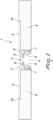
Figure 1 is a schematic perspective view of a possible embodiment of an electric power supply module for ceilings, walls made of plasterboard and the like according to the invention in a step of installation; -
Figure 2 is a schematic front view of the module ofFigure 1 ; -
Figure 3 is a schematic perspective view of the module ofFigure 1 with a potential user appliance facing it; -
Figure 4 is a schematic perspective top view of the module ofFigure 1 with a potential user appliance installed. - With particular reference to the figures, the
reference numeral 1 generally designates an electric power supply module for ceilings A, walls made of plasterboard and the like. - The
module 1 advantageously comprises at least one profiledelement 2 which has at least onemain body 3 which forms a substantiallyU-shaped compartment 4 and twolateral laminas 5 which lie on planes which are substantially parallel and proximate to the plane that contains thebase 6 of themain body 3. - The
module 1 according to the invention further comprises at least one support made ofdielectric material 7, which does not conduct electricity, coupled within thecompartment 4 of the at least onemain body 3 of the at least one profiledelement 2 along its entire length. - The profiled
element 2 can be symmetrical or asymmetrical and therefore themain body 3 can be in a central or off-center position according to the specific manner of embodiment. - The
module 1 according to the invention further comprises at least onewire 8 made of a material chosen from electrically conducting, optically conducting and the like, which is coupled rigidly to thesupport 7 made of dielectric material, along its entire length. - Finally, the
module 1 comprises at least twopanels 9 made of a material of a type chosen preferably from plasterboard panels, wood panels, wood derivative panels, panels made of mineral fibers, panels made of composite material, panels made of polymeric fiber, panels made of paper derivatives, metallic meshes and a combination thereof. - Each
panel 9 in turn comprises at least onerespective recess 10 whose shape and dimensions are substantially complementary to those of one of thelateral laminas 5 of the profiledelement 2 for the accommodation thereof so that thelamina 5 does not protrude from the surface of thepanel 9. - With particular reference to an embodiment of unquestionable interest in practice and in application, it is possible to advantageously interpose between the
panels 9 and the profiledelement 2 an adhesive material for the rigid coupling of eachpanel 9 to a respective side of the profiledelement 2. - In particular, each
lamina 5 is accommodated within the respective recess 10 (and adhesively bonded thereat) and the lateral surface of themain body 3 rests on a perimeter edge which is contiguous to therecess 10 of the respective panel 9 (and is adhesively bonded thereto). - The expression "adhesive material" is to be understood as including, in the present description, all adhesive and/or cohesive substances, including therefore all glues, silicone derivatives, resins, so-called hot glue, premixes for building use (based on plaster, cement and other materials), double adhesive sheets and the like.
- It is not excluded, in any case, in alternative embodiments which are fully within the protective scope of the present invention, to adopt other methods for fixing the profiled
element 2 to thepanels 9 which provide for screws, rivets, screw anchors, seams and combinations of some of the described methods (including also adhesive bonding). - It is further specified that with reference to the embodiment shown by way of non-limiting example in the accompanying figures, the supports made of
dielectric material 7, which are not electrically conducting, coupled inside thecompartment 4 of the at least onemain body 3 of the at least one profiledelement 2 may conveniently be two, arranged symmetrically, each preset to support at least onerespective wire 8 made of electrically conducting material. - In this manner, if the
wires 8 are preset to supply AC electric power to specific appliances B which will be installed on the profiledelement 2, thewire 8 on the right might be the one that corresponds to the conductor known as "phase" and the left one might be the one that corresponds to the conductor known as "neutral". In this case, the presence of anadditional wire 8, preset for connection of the user appliance B to the ground system, is not excluded. - If instead the
wires 8 are preset to supply DC electric power to specific appliances B which will be installed on the profiledelement 2, the wire on the right 8 and the left one would constitute the outgoing portion and the return portion of a circuit in which the appliances B are connected in parallel. - It is further specified that the
wires 8 made of a material chosen from electrically conducting, optically conducting and the like, coupled to each support made of dielectric material, might conveniently be two (as shown by way of non-limiting example in the accompanying figures), arranged at different heights with respect to the thickness of themain body 3. - In this case the
wires 8 might also be of a different type: some wires might be preset to supply electromotive force and other wires might lead to a data line transceiver. - The accommodation of an even greater number of
wires 8 than the examples shown in the accompanying figures is not excluded. - It is specified that each
module 1 comprises, at its ends, respective electrical/optical connection terminals for the electrical/optical connection of the at least onewire 8, made of a material chosen from electrically conducting, optically conducting and the like, of afirst module 1 to the at least onecorresponding wire 8 of asecond module 1. - In this manner, during the installation of the
modules 1, their wiring is particularly facilitated since the simple juxtaposition of the respective ends will ensure the effective connection of thewires 8 that are present in onemodule 1 to those of thecontiguous module 1, providing the connection of thewires 8 by means of the specific electrical/optical connection terminals. - It is specified furthermore that the profiled
element 2 can have positively any shape chosen preferably from linear, curved, angular, T-shaped, cross-shaped, Y-shaped, and the like. - In this manner it is possible to create, on the installation ceiling A or wall, paths for the quick connection of appliances B (defined by the arrangement of the guide formed by the
compartments 4 of all the profiledelements 2 that are present on contiguous modules 1) of any shape, with a linear or curved orientation, which corresponds to that of a broken line and/or of a mixed line, as well as provided with bifurcations, joints and path crossings. - It is therefore possible to provide any type of wiring in a simple manner: this wiring provision allows to arrange the appliances B in a plurality of different configurations which can be reconfigured easily (if necessary).
- It is further specified that the profiled
element 2 can comprise conveniently respective stiffening ribs, which can constitute anchoring elements for an appliance B of a type chosen from electric power user devices and data processing, transmission, reception, acquisition devices, as well as any combination thereof. - In order to facilitate the electrical connection of the appliances B, the adoption of
wires 8 which are not electrically insulated (not covered by respective insulating sheaths made of dielectric material) and/or ofwires 8 which are only partially covered with an insulating sheath (so as to leave exposed a part of their surface against which respective sliding contact terminals of the appliances B can abut) is provided. - It is further specified that each
wire 8 made of a material chosen from electrically conducting, optically conducting and the like may advantageously be connected, by means of at least one respective front of anend module 1 of a series of aligned and connectedmodules 1, to a source of a type chosen preferably from a wired electric circuit, the electric power supply grid, a battery of electric power storage units, a data network, a telephone network, a network device such as a router, a modem, and the like, a telecommunication apparatus such as a TV antenna system, and the like. - In this manner, thanks to the electrical and optical continuity ensured by the mutual coupling of the
wires 8 ofcontiguous modules 1, in each point of the path formed by thecompartment 4 of anymodule 1 that is present in the predefined path (along the ceiling A and/or the wall) it is easily possible to apply an appliance B, which will be powered correctly. - From a constructive standpoint, it is specified that the profiled
element 2 is preferably made of metallic material, particularly extruded aluminum. This material is particularly indicated by virtue of its limited specific gravity and its excellent mechanical characteristics. - As an alternative, the profiled
element 2 may be made of a material chosen from polymeric, composite and the like. - It is specified that some polymeric materials and many composite materials have mechanical characteristics that can be compared with (and are even greater than) those of aluminum, but have a specific gravity that is even lower than that of said metal.
- Polymers and composite materials generally behave as dielectric materials: in this case, therefore, the at least one
support 7 made of dielectric material can be embedded directly in themain body 3 of said profiledelement 2. - Advantageously, the present invention solves the problems described earlier, providing an electric
power supply module 1 for ceilings A, walls made of plasterboard and the like that is easy to install. - In fact, once the
module 1 has been arranged on the installation surface (ceiling A, wall and the like) it is possible to proceed with finishing operations (arrangements of coupling meshes at the surfaces of discontinuity, filling, skimming and painting) in a manner exactly identical to what is normally provided for the provision of traditional surfaces made of plasterboard and other similar materials. - It is fundamental to point out that the substantial absence of operations of preventive operations for preparation makes the entire installation of paths constituted by a series of
contiguous modules 1 according to the invention particularly simple and quick. - Conveniently, in fact, the
module 1 according to the invention requires specific provisions in the wall and/or ceiling in which it is to be installed, since it is necessary to provide the connection of thewires 8 to a respective system (as illustrated previously) only at one of the ends of the path formed by the series ofcontiguous modules 1. - The
module 1 according to the invention can be advantageously coupled to the installation ceiling A and/or wall without the need for brackets and supports. - Usefully, the
module 1 according to the invention has a minimal visual impact once installed. - It is specified that once all the appliances B have been connected along the path formed by the series of
contiguous modules 1 it is possible to install elements for closing thecompartment 4 so as to minimize the visual impact of the entire path ofmodules 1. - Advantageously, the
module 1 has a thickness which is similar to that of a traditional panel made of plasterboard: this allows its installation also in all cases in which plasterboard panels are installed as infilling directly in contact with surface (ceiling A and/or wall B). - According to this principle, one might even use the
modules 1 to provide the entire electrical and data system of an environment, by providing, among the possible appliances B that can be coupled to the profiledelement 2, also with electrical outlets, switches and the like. Such an embodiment is assuredly simpler if one uses appliances B of the controlled type, i.e., indicated for domotics applications, i.e., so that they can be controlled and configured easily, minimizing the number of direct connections by means of electrical wires. - This possibility is particularly interesting for the provision of shops, display windows and exhibition stands, in which the possibility of unlimited reconfigurations and simplicity of installation are fundamentally interesting characteristics.
- Validly, the
module 1 according to the invention is relatively simple to provide in practice and has low costs: these characteristics make themodule 1 according to the invention an innovation of assured application. - The invention thus conceived is susceptible of numerous modifications and variations, all of which are within the scope of the appended claims; all the details may furthermore be replaced with other technically equivalent elements.
- In the illustrated embodiments, individual characteristics, given in relation to specific examples, may actually be interchanged with other different characteristics that exist in other embodiments.
- In practice, the materials used, as well as the dimensions, may be any according to the requirements and the state of the art.
- Where technical features mentioned in any claim are followed by reference signs, those reference signs have been included for the sole purpose of increasing the intelligibility of the claims and accordingly such reference signs do not have any limiting effect on the interpretation of each element identified by way of example by such reference signs.
Claims (10)
- An electric power supply module for ceilings (A), walls made of plasterboard and the like, wherein it comprises- at least one profiled element (2) provided with at least one main body (3) which forms a substantially U-shaped compartment (4) and two lateral laminas (5) which lie on a plane that is substantially parallel and proximate to the plane that contains the base (6) of said main body (3);- at least one support (7) made of dielectric material, which is not electrically conducting and is coupled inside the compartment (4) of said at least one main body (3) of said at least one profiled element (2) along its entire length;- at least one wire (8) made of material chosen from electrically conducting, optically conducting and the like, rigidly coupled to said support (7) made of dielectric material along its entire length;- at least two panels (9) made of material of a type preferably chosen from plasterboard panels, wood panels, panels made of wood derivatives, panels made of mineral fibers, panels made of composite material, panels made of polymeric material, panels made of paper derivatives, metallic meshes and combinations thereof, each panel (9) comprising a respective recess (10) whose shape and dimensions are substantially complementary to those of one of said lateral laminas (5) of said profiled element (2) for its accommodation without protrusion of said lamina (5) from the surface of said panel (9).
- The module according to claim 1, wherein an adhesive is interposed between said panels (9) and said profiled element (2) for the rigid coupling of each panel (9) to a respective side of said profiled element (2), with said lamina (5) accommodated within said recess (10) and the lateral surface of said main body (3) resting on a perimeter edge, contiguous to said recess (10), of the respective panel (9).
- The module according to claim 1, wherein said electrically non-conducting supports (7) made of dielectric material, coupled inside the compartment (4) of said at least one main body (3) of said at least one profiled element (2), are two, arranged symmetrically, each preset to support at least one respective wire (8) made of electrically conducting material.
- The module according to claim 3, wherein said wires (8) made of a material chosen from electrically conducting, optically conducting and the like, coupled to each support (7) made of dielectric material, are two, arranged at different heights with respect to the thickness of said main body (3).
- The module according to claim 1, wherein it comprises, at the ends, respective electrical/optical connection terminals for the electrical/optical connection of the at least one wire (8), made of a material chosen from electrically conducting, optically conducting and the like, of a first module (1) to the at least one corresponding wire (8) of a second module (1).
- The module according to claim 1 wherein said profiled element (2) has a shape preferably chosen from linear, curved, angular, T-shaped, cross-shaped, Y-shaped, and the like.
- The module according to one or more of the preceding claims, wherein said profiled element (2) comprises respective stiffening ribs, which constitute anchoring elements for an appliance (B) of a type chosen from electric power user devices and data processing, transmission, reception, acquisition devices, and a combination thereof.
- The module according to one or more of the preceding claims, wherein at least one wire (8) made of material chosen from electrically conducting, optically conducting and the like, is connected, by means of at least one respective front of an end module (1) of a series of aligned and contiguous modules (1), to a source of a type chosen preferably from a wired electric circuit, the electric power supply grid, a battery of electric power storage units, a data network, a telephone network, a network device such as a router, a modem and the like, a telecommunication system such as a TV antenna system, and the like.
- The module according to one or more of the preceding claims, wherein said profiled element (2) is made of metallic material, particularly aluminum.
- The module according to one or more of the preceding claims, wherein said profiled element (2) is made of a material chosen from polymeric, composite and the like, said at least one support (7) made of dielectric material being embedded directly in said main body (3).
Applications Claiming Priority (1)
| Application Number | Priority Date | Filing Date | Title |
|---|---|---|---|
| IT202020000006956U IT202000006956U1 (en) | 2020-12-17 | 2020-12-17 | POWER SUPPLY MODULE FOR CEILINGS, PLASTERBOARD WALLS AND SIMILAR |
Publications (2)
| Publication Number | Publication Date |
|---|---|
| EP4016774A1 EP4016774A1 (en) | 2022-06-22 |
| EP4016774B1 true EP4016774B1 (en) | 2023-05-10 |
Family
ID=78829412
Family Applications (1)
| Application Number | Title | Priority Date | Filing Date |
|---|---|---|---|
| EP21212327.7A Active EP4016774B1 (en) | 2020-12-17 | 2021-12-03 | Electric power supply module for ceilings, walls made of plasterboard and the like |
Country Status (2)
| Country | Link |
|---|---|
| EP (1) | EP4016774B1 (en) |
| IT (1) | IT202000006956U1 (en) |
Citations (3)
| Publication number | Priority date | Publication date | Assignee | Title |
|---|---|---|---|---|
| JPS58150641A (en) * | 1982-03-04 | 1983-09-07 | 清水建設株式会社 | ceiling structure |
| US20150225067A1 (en) * | 2014-02-07 | 2015-08-13 | Airbus Operations Gmbh | Rail system for seat assembly in an aircraft |
| US20150225066A1 (en) * | 2014-02-07 | 2015-08-13 | Airbus Operations Gmbh | Rail system for seat assembly in an aircraft |
Family Cites Families (3)
| Publication number | Priority date | Publication date | Assignee | Title |
|---|---|---|---|---|
| JPS5136532B1 (en) * | 1970-12-07 | 1976-10-08 | ||
| ITVI20110268A1 (en) * | 2011-10-05 | 2013-04-06 | Gemino S R L | MODULAR CONTRA-CEILING SYSTEM |
| US10501936B2 (en) * | 2017-03-01 | 2019-12-10 | Price Industries Limited | Modular ceiling system |
-
2020
- 2020-12-17 IT IT202020000006956U patent/IT202000006956U1/en unknown
-
2021
- 2021-12-03 EP EP21212327.7A patent/EP4016774B1/en active Active
Patent Citations (3)
| Publication number | Priority date | Publication date | Assignee | Title |
|---|---|---|---|---|
| JPS58150641A (en) * | 1982-03-04 | 1983-09-07 | 清水建設株式会社 | ceiling structure |
| US20150225067A1 (en) * | 2014-02-07 | 2015-08-13 | Airbus Operations Gmbh | Rail system for seat assembly in an aircraft |
| US20150225066A1 (en) * | 2014-02-07 | 2015-08-13 | Airbus Operations Gmbh | Rail system for seat assembly in an aircraft |
Also Published As
| Publication number | Publication date |
|---|---|
| IT202000006956U1 (en) | 2022-06-17 |
| EP4016774A1 (en) | 2022-06-22 |
Similar Documents
| Publication | Publication Date | Title |
|---|---|---|
| KR100397581B1 (en) | Surface Mount Multipurpose Wiring | |
| KR100836270B1 (en) | Cell Bracket for Cell | |
| CN101286609B (en) | Electrical connection device for contacts, especially blade contacts | |
| TWI493815B (en) | Electrical power distribution system | |
| USRE42085E1 (en) | Flat surface-mounted multi-purpose wire | |
| WO2018114681A1 (en) | Laminated busbar with protective earth | |
| CN102047432A (en) | Photovoltaic array, framework, and methods of installation and use | |
| MX2009000195A (en) | LOAD CONTROL DEVICE WITH A DIVIDED ENVIRONMENT. | |
| CA2312563C (en) | Flat surface-mounted multi-purpose wire | |
| CN106877180A (en) | For the system that the insulating trip using bending isolates power conductor | |
| EP4016774B1 (en) | Electric power supply module for ceilings, walls made of plasterboard and the like | |
| EP0382748A1 (en) | Current connection member for large amperages, especially to be used in metal-enclosed electric systems | |
| EP3104470B1 (en) | Socket assembly with multiple flush-mounting boxes | |
| FI87710C (en) | Encapsulation system for mounting network and / or signal conductors and process for manufacturing encapsulation parts | |
| WO2009122325A1 (en) | Tile spacer | |
| KR100672960B1 (en) | Busbar support | |
| WO2020244749A1 (en) | Coupling element for electrically coupling the lateral connecting portions of a first and second laminated busbar via a circuit breaker and an arrangement including such an element | |
| RU2822924C1 (en) | Noise-proof power supply bus | |
| CN110912043A (en) | A cable trough and its power distribution unit | |
| KR20240139577A (en) | Power transferring busway and busway system having the same | |
| KR20170044795A (en) | Structure for bonding bus bars | |
| AU761804B2 (en) | Flat surface-mounted multi-purpose wire | |
| TR202022303Y (en) | Five-pole combined horizontal distribution set | |
| NO325193B1 (en) | Installation Benefits | |
| JPH10322860A (en) | Cable track |
Legal Events
| Date | Code | Title | Description |
|---|---|---|---|
| PUAI | Public reference made under article 153(3) epc to a published international application that has entered the european phase |
Free format text: ORIGINAL CODE: 0009012 |
|
| STAA | Information on the status of an ep patent application or granted ep patent |
Free format text: STATUS: THE APPLICATION HAS BEEN PUBLISHED |
|
| AK | Designated contracting states |
Kind code of ref document: A1 Designated state(s): AL AT BE BG CH CY CZ DE DK EE ES FI FR GB GR HR HU IE IS IT LI LT LU LV MC MK MT NL NO PL PT RO RS SE SI SK SM TR |
|
| STAA | Information on the status of an ep patent application or granted ep patent |
Free format text: STATUS: REQUEST FOR EXAMINATION WAS MADE |
|
| 17P | Request for examination filed |
Effective date: 20220714 |
|
| RBV | Designated contracting states (corrected) |
Designated state(s): AL AT BE BG CH CY CZ DE DK EE ES FI FR GB GR HR HU IE IS IT LI LT LU LV MC MK MT NL NO PL PT RO RS SE SI SK SM TR |
|
| GRAP | Despatch of communication of intention to grant a patent |
Free format text: ORIGINAL CODE: EPIDOSNIGR1 |
|
| STAA | Information on the status of an ep patent application or granted ep patent |
Free format text: STATUS: GRANT OF PATENT IS INTENDED |
|
| INTG | Intention to grant announced |
Effective date: 20221129 |
|
| GRAS | Grant fee paid |
Free format text: ORIGINAL CODE: EPIDOSNIGR3 |
|
| GRAA | (expected) grant |
Free format text: ORIGINAL CODE: 0009210 |
|
| STAA | Information on the status of an ep patent application or granted ep patent |
Free format text: STATUS: THE PATENT HAS BEEN GRANTED |
|
| AK | Designated contracting states |
Kind code of ref document: B1 Designated state(s): AL AT BE BG CH CY CZ DE DK EE ES FI FR GB GR HR HU IE IS IT LI LT LU LV MC MK MT NL NO PL PT RO RS SE SI SK SM TR |
|
| REG | Reference to a national code |
Ref country code: GB Ref legal event code: FG4D |
|
| REG | Reference to a national code |
Ref country code: AT Ref legal event code: REF Ref document number: 1567680 Country of ref document: AT Kind code of ref document: T Effective date: 20230515 Ref country code: CH Ref legal event code: EP |
|
| REG | Reference to a national code |
Ref country code: DE Ref legal event code: R096 Ref document number: 602021002333 Country of ref document: DE |
|
| REG | Reference to a national code |
Ref country code: IE Ref legal event code: FG4D |
|
| REG | Reference to a national code |
Ref country code: LT Ref legal event code: MG9D |
|
| REG | Reference to a national code |
Ref country code: NL Ref legal event code: MP Effective date: 20230510 |
|
| REG | Reference to a national code |
Ref country code: AT Ref legal event code: MK05 Ref document number: 1567680 Country of ref document: AT Kind code of ref document: T Effective date: 20230510 |
|
| PG25 | Lapsed in a contracting state [announced via postgrant information from national office to epo] |
Ref country code: SE Free format text: LAPSE BECAUSE OF FAILURE TO SUBMIT A TRANSLATION OF THE DESCRIPTION OR TO PAY THE FEE WITHIN THE PRESCRIBED TIME-LIMIT Effective date: 20230510 Ref country code: PT Free format text: LAPSE BECAUSE OF FAILURE TO SUBMIT A TRANSLATION OF THE DESCRIPTION OR TO PAY THE FEE WITHIN THE PRESCRIBED TIME-LIMIT Effective date: 20230911 Ref country code: NO Free format text: LAPSE BECAUSE OF FAILURE TO SUBMIT A TRANSLATION OF THE DESCRIPTION OR TO PAY THE FEE WITHIN THE PRESCRIBED TIME-LIMIT Effective date: 20230810 Ref country code: NL Free format text: LAPSE BECAUSE OF FAILURE TO SUBMIT A TRANSLATION OF THE DESCRIPTION OR TO PAY THE FEE WITHIN THE PRESCRIBED TIME-LIMIT Effective date: 20230510 Ref country code: ES Free format text: LAPSE BECAUSE OF FAILURE TO SUBMIT A TRANSLATION OF THE DESCRIPTION OR TO PAY THE FEE WITHIN THE PRESCRIBED TIME-LIMIT Effective date: 20230510 Ref country code: AT Free format text: LAPSE BECAUSE OF FAILURE TO SUBMIT A TRANSLATION OF THE DESCRIPTION OR TO PAY THE FEE WITHIN THE PRESCRIBED TIME-LIMIT Effective date: 20230510 |
|
| PG25 | Lapsed in a contracting state [announced via postgrant information from national office to epo] |
Ref country code: RS Free format text: LAPSE BECAUSE OF FAILURE TO SUBMIT A TRANSLATION OF THE DESCRIPTION OR TO PAY THE FEE WITHIN THE PRESCRIBED TIME-LIMIT Effective date: 20230510 Ref country code: PL Free format text: LAPSE BECAUSE OF FAILURE TO SUBMIT A TRANSLATION OF THE DESCRIPTION OR TO PAY THE FEE WITHIN THE PRESCRIBED TIME-LIMIT Effective date: 20230510 Ref country code: LV Free format text: LAPSE BECAUSE OF FAILURE TO SUBMIT A TRANSLATION OF THE DESCRIPTION OR TO PAY THE FEE WITHIN THE PRESCRIBED TIME-LIMIT Effective date: 20230510 Ref country code: LT Free format text: LAPSE BECAUSE OF FAILURE TO SUBMIT A TRANSLATION OF THE DESCRIPTION OR TO PAY THE FEE WITHIN THE PRESCRIBED TIME-LIMIT Effective date: 20230510 Ref country code: IS Free format text: LAPSE BECAUSE OF FAILURE TO SUBMIT A TRANSLATION OF THE DESCRIPTION OR TO PAY THE FEE WITHIN THE PRESCRIBED TIME-LIMIT Effective date: 20230910 Ref country code: HR Free format text: LAPSE BECAUSE OF FAILURE TO SUBMIT A TRANSLATION OF THE DESCRIPTION OR TO PAY THE FEE WITHIN THE PRESCRIBED TIME-LIMIT Effective date: 20230510 Ref country code: GR Free format text: LAPSE BECAUSE OF FAILURE TO SUBMIT A TRANSLATION OF THE DESCRIPTION OR TO PAY THE FEE WITHIN THE PRESCRIBED TIME-LIMIT Effective date: 20230811 |
|
| PG25 | Lapsed in a contracting state [announced via postgrant information from national office to epo] |
Ref country code: FI Free format text: LAPSE BECAUSE OF FAILURE TO SUBMIT A TRANSLATION OF THE DESCRIPTION OR TO PAY THE FEE WITHIN THE PRESCRIBED TIME-LIMIT Effective date: 20230510 |
|
| PG25 | Lapsed in a contracting state [announced via postgrant information from national office to epo] |
Ref country code: SK Free format text: LAPSE BECAUSE OF FAILURE TO SUBMIT A TRANSLATION OF THE DESCRIPTION OR TO PAY THE FEE WITHIN THE PRESCRIBED TIME-LIMIT Effective date: 20230510 |
|
| PG25 | Lapsed in a contracting state [announced via postgrant information from national office to epo] |
Ref country code: SM Free format text: LAPSE BECAUSE OF FAILURE TO SUBMIT A TRANSLATION OF THE DESCRIPTION OR TO PAY THE FEE WITHIN THE PRESCRIBED TIME-LIMIT Effective date: 20230510 Ref country code: SK Free format text: LAPSE BECAUSE OF FAILURE TO SUBMIT A TRANSLATION OF THE DESCRIPTION OR TO PAY THE FEE WITHIN THE PRESCRIBED TIME-LIMIT Effective date: 20230510 Ref country code: RO Free format text: LAPSE BECAUSE OF FAILURE TO SUBMIT A TRANSLATION OF THE DESCRIPTION OR TO PAY THE FEE WITHIN THE PRESCRIBED TIME-LIMIT Effective date: 20230510 Ref country code: EE Free format text: LAPSE BECAUSE OF FAILURE TO SUBMIT A TRANSLATION OF THE DESCRIPTION OR TO PAY THE FEE WITHIN THE PRESCRIBED TIME-LIMIT Effective date: 20230510 Ref country code: DK Free format text: LAPSE BECAUSE OF FAILURE TO SUBMIT A TRANSLATION OF THE DESCRIPTION OR TO PAY THE FEE WITHIN THE PRESCRIBED TIME-LIMIT Effective date: 20230510 Ref country code: CZ Free format text: LAPSE BECAUSE OF FAILURE TO SUBMIT A TRANSLATION OF THE DESCRIPTION OR TO PAY THE FEE WITHIN THE PRESCRIBED TIME-LIMIT Effective date: 20230510 |
|
| REG | Reference to a national code |
Ref country code: DE Ref legal event code: R097 Ref document number: 602021002333 Country of ref document: DE |
|
| PLBE | No opposition filed within time limit |
Free format text: ORIGINAL CODE: 0009261 |
|
| STAA | Information on the status of an ep patent application or granted ep patent |
Free format text: STATUS: NO OPPOSITION FILED WITHIN TIME LIMIT |
|
| 26N | No opposition filed |
Effective date: 20240213 |
|
| PG25 | Lapsed in a contracting state [announced via postgrant information from national office to epo] |
Ref country code: SI Free format text: LAPSE BECAUSE OF FAILURE TO SUBMIT A TRANSLATION OF THE DESCRIPTION OR TO PAY THE FEE WITHIN THE PRESCRIBED TIME-LIMIT Effective date: 20230510 |
|
| PG25 | Lapsed in a contracting state [announced via postgrant information from national office to epo] |
Ref country code: SI Free format text: LAPSE BECAUSE OF FAILURE TO SUBMIT A TRANSLATION OF THE DESCRIPTION OR TO PAY THE FEE WITHIN THE PRESCRIBED TIME-LIMIT Effective date: 20230510 |
|
| REG | Reference to a national code |
Ref country code: DE Ref legal event code: R119 Ref document number: 602021002333 Country of ref document: DE |
|
| PG25 | Lapsed in a contracting state [announced via postgrant information from national office to epo] |
Ref country code: LU Free format text: LAPSE BECAUSE OF NON-PAYMENT OF DUE FEES Effective date: 20231203 |
|
| PG25 | Lapsed in a contracting state [announced via postgrant information from national office to epo] |
Ref country code: MC Free format text: LAPSE BECAUSE OF FAILURE TO SUBMIT A TRANSLATION OF THE DESCRIPTION OR TO PAY THE FEE WITHIN THE PRESCRIBED TIME-LIMIT Effective date: 20230510 |
|
| REG | Reference to a national code |
Ref country code: BE Ref legal event code: MM Effective date: 20231231 |
|
| PG25 | Lapsed in a contracting state [announced via postgrant information from national office to epo] |
Ref country code: MC Free format text: LAPSE BECAUSE OF FAILURE TO SUBMIT A TRANSLATION OF THE DESCRIPTION OR TO PAY THE FEE WITHIN THE PRESCRIBED TIME-LIMIT Effective date: 20230510 Ref country code: LU Free format text: LAPSE BECAUSE OF NON-PAYMENT OF DUE FEES Effective date: 20231203 |
|
| REG | Reference to a national code |
Ref country code: IE Ref legal event code: MM4A |
|
| PG25 | Lapsed in a contracting state [announced via postgrant information from national office to epo] |
Ref country code: DE Free format text: LAPSE BECAUSE OF NON-PAYMENT OF DUE FEES Effective date: 20240702 Ref country code: IE Free format text: LAPSE BECAUSE OF NON-PAYMENT OF DUE FEES Effective date: 20231203 |
|
| PG25 | Lapsed in a contracting state [announced via postgrant information from national office to epo] |
Ref country code: BE Free format text: LAPSE BECAUSE OF NON-PAYMENT OF DUE FEES Effective date: 20231231 |
|
| PG25 | Lapsed in a contracting state [announced via postgrant information from national office to epo] |
Ref country code: FR Free format text: LAPSE BECAUSE OF NON-PAYMENT OF DUE FEES Effective date: 20231231 |
|
| PG25 | Lapsed in a contracting state [announced via postgrant information from national office to epo] |
Ref country code: IE Free format text: LAPSE BECAUSE OF NON-PAYMENT OF DUE FEES Effective date: 20231203 Ref country code: FR Free format text: LAPSE BECAUSE OF NON-PAYMENT OF DUE FEES Effective date: 20231231 Ref country code: DE Free format text: LAPSE BECAUSE OF NON-PAYMENT OF DUE FEES Effective date: 20240702 Ref country code: BE Free format text: LAPSE BECAUSE OF NON-PAYMENT OF DUE FEES Effective date: 20231231 |
|
| PG25 | Lapsed in a contracting state [announced via postgrant information from national office to epo] |
Ref country code: BG Free format text: LAPSE BECAUSE OF FAILURE TO SUBMIT A TRANSLATION OF THE DESCRIPTION OR TO PAY THE FEE WITHIN THE PRESCRIBED TIME-LIMIT Effective date: 20230510 |
|
| PG25 | Lapsed in a contracting state [announced via postgrant information from national office to epo] |
Ref country code: BG Free format text: LAPSE BECAUSE OF FAILURE TO SUBMIT A TRANSLATION OF THE DESCRIPTION OR TO PAY THE FEE WITHIN THE PRESCRIBED TIME-LIMIT Effective date: 20230510 |
|
| PG25 | Lapsed in a contracting state [announced via postgrant information from national office to epo] |
Ref country code: CY Free format text: LAPSE BECAUSE OF FAILURE TO SUBMIT A TRANSLATION OF THE DESCRIPTION OR TO PAY THE FEE WITHIN THE PRESCRIBED TIME-LIMIT; INVALID AB INITIO Effective date: 20211203 |
|
| REG | Reference to a national code |
Ref country code: CH Ref legal event code: PL |
|
| PG25 | Lapsed in a contracting state [announced via postgrant information from national office to epo] |
Ref country code: CH Free format text: LAPSE BECAUSE OF NON-PAYMENT OF DUE FEES Effective date: 20241231 |
|
| PG25 | Lapsed in a contracting state [announced via postgrant information from national office to epo] |
Ref country code: TR Free format text: LAPSE BECAUSE OF FAILURE TO SUBMIT A TRANSLATION OF THE DESCRIPTION OR TO PAY THE FEE WITHIN THE PRESCRIBED TIME-LIMIT Effective date: 20230510 |
|
| PGFP | Annual fee paid to national office [announced via postgrant information from national office to epo] |
Ref country code: IT Payment date: 20251124 Year of fee payment: 5 |