EP4016744A1 - Braided part connection structure - Google Patents
Braided part connection structure Download PDFInfo
- Publication number
- EP4016744A1 EP4016744A1 EP21213310.2A EP21213310A EP4016744A1 EP 4016744 A1 EP4016744 A1 EP 4016744A1 EP 21213310 A EP21213310 A EP 21213310A EP 4016744 A1 EP4016744 A1 EP 4016744A1
- Authority
- EP
- European Patent Office
- Prior art keywords
- braided part
- shield member
- braided
- welding
- shield
- Prior art date
- Legal status (The legal status is an assumption and is not a legal conclusion. Google has not performed a legal analysis and makes no representation as to the accuracy of the status listed.)
- Granted
Links
Images



Classifications
-
- H—ELECTRICITY
- H01—ELECTRIC ELEMENTS
- H01R—ELECTRICALLY-CONDUCTIVE CONNECTIONS; STRUCTURAL ASSOCIATIONS OF A PLURALITY OF MUTUALLY-INSULATED ELECTRICAL CONNECTING ELEMENTS; COUPLING DEVICES; CURRENT COLLECTORS
- H01R9/00—Structural associations of a plurality of mutually-insulated electrical connecting elements, e.g. terminal strips or terminal blocks; Terminals or binding posts mounted upon a base or in a case; Bases therefor
- H01R9/03—Connectors arranged to contact a plurality of the conductors of a multiconductor cable, e.g. tapping connections
- H01R9/05—Connectors arranged to contact a plurality of the conductors of a multiconductor cable, e.g. tapping connections for coaxial cables
- H01R9/0512—Connections to an additional grounding conductor
-
- H—ELECTRICITY
- H01—ELECTRIC ELEMENTS
- H01R—ELECTRICALLY-CONDUCTIVE CONNECTIONS; STRUCTURAL ASSOCIATIONS OF A PLURALITY OF MUTUALLY-INSULATED ELECTRICAL CONNECTING ELEMENTS; COUPLING DEVICES; CURRENT COLLECTORS
- H01R4/00—Electrically-conductive connections between two or more conductive members in direct contact, i.e. touching one another; Means for effecting or maintaining such contact; Electrically-conductive connections having two or more spaced connecting locations for conductors and using contact members penetrating insulation
- H01R4/02—Soldered or welded connections
- H01R4/023—Soldered or welded connections between cables or wires and terminals
-
- H—ELECTRICITY
- H01—ELECTRIC ELEMENTS
- H01R—ELECTRICALLY-CONDUCTIVE CONNECTIONS; STRUCTURAL ASSOCIATIONS OF A PLURALITY OF MUTUALLY-INSULATED ELECTRICAL CONNECTING ELEMENTS; COUPLING DEVICES; CURRENT COLLECTORS
- H01R4/00—Electrically-conductive connections between two or more conductive members in direct contact, i.e. touching one another; Means for effecting or maintaining such contact; Electrically-conductive connections having two or more spaced connecting locations for conductors and using contact members penetrating insulation
- H01R4/02—Soldered or welded connections
- H01R4/029—Welded connections
-
- H—ELECTRICITY
- H01—ELECTRIC ELEMENTS
- H01B—CABLES; CONDUCTORS; INSULATORS; SELECTION OF MATERIALS FOR THEIR CONDUCTIVE, INSULATING OR DIELECTRIC PROPERTIES
- H01B7/00—Insulated conductors or cables characterised by their form
- H01B7/17—Protection against damage caused by external factors, e.g. sheaths or armouring
-
- H—ELECTRICITY
- H01—ELECTRIC ELEMENTS
- H01R—ELECTRICALLY-CONDUCTIVE CONNECTIONS; STRUCTURAL ASSOCIATIONS OF A PLURALITY OF MUTUALLY-INSULATED ELECTRICAL CONNECTING ELEMENTS; COUPLING DEVICES; CURRENT COLLECTORS
- H01R13/00—Details of coupling devices of the kinds covered by groups H01R12/70 or H01R24/00 - H01R33/00
- H01R13/648—Protective earth or shield arrangements on coupling devices, e.g. anti-static shielding
- H01R13/658—High frequency shielding arrangements, e.g. against EMI [Electro-Magnetic Interference] or EMP [Electro-Magnetic Pulse]
- H01R13/6591—Specific features or arrangements of connection of shield to conductive members
- H01R13/6592—Specific features or arrangements of connection of shield to conductive members the conductive member being a shielded cable
- H01R13/6593—Specific features or arrangements of connection of shield to conductive members the conductive member being a shielded cable the shield being composed of different pieces
-
- H—ELECTRICITY
- H01—ELECTRIC ELEMENTS
- H01R—ELECTRICALLY-CONDUCTIVE CONNECTIONS; STRUCTURAL ASSOCIATIONS OF A PLURALITY OF MUTUALLY-INSULATED ELECTRICAL CONNECTING ELEMENTS; COUPLING DEVICES; CURRENT COLLECTORS
- H01R4/00—Electrically-conductive connections between two or more conductive members in direct contact, i.e. touching one another; Means for effecting or maintaining such contact; Electrically-conductive connections having two or more spaced connecting locations for conductors and using contact members penetrating insulation
- H01R4/58—Electrically-conductive connections between two or more conductive members in direct contact, i.e. touching one another; Means for effecting or maintaining such contact; Electrically-conductive connections having two or more spaced connecting locations for conductors and using contact members penetrating insulation characterised by the form or material of the contacting members
- H01R4/60—Connections between or with tubular conductors
-
- H—ELECTRICITY
- H01—ELECTRIC ELEMENTS
- H01R—ELECTRICALLY-CONDUCTIVE CONNECTIONS; STRUCTURAL ASSOCIATIONS OF A PLURALITY OF MUTUALLY-INSULATED ELECTRICAL CONNECTING ELEMENTS; COUPLING DEVICES; CURRENT COLLECTORS
- H01R2103/00—Two poles
-
- H—ELECTRICITY
- H01—ELECTRIC ELEMENTS
- H01R—ELECTRICALLY-CONDUCTIVE CONNECTIONS; STRUCTURAL ASSOCIATIONS OF A PLURALITY OF MUTUALLY-INSULATED ELECTRICAL CONNECTING ELEMENTS; COUPLING DEVICES; CURRENT COLLECTORS
- H01R4/00—Electrically-conductive connections between two or more conductive members in direct contact, i.e. touching one another; Means for effecting or maintaining such contact; Electrically-conductive connections having two or more spaced connecting locations for conductors and using contact members penetrating insulation
- H01R4/10—Electrically-conductive connections between two or more conductive members in direct contact, i.e. touching one another; Means for effecting or maintaining such contact; Electrically-conductive connections having two or more spaced connecting locations for conductors and using contact members penetrating insulation effected solely by twisting, wrapping, bending, crimping, or other permanent deformation
- H01R4/18—Electrically-conductive connections between two or more conductive members in direct contact, i.e. touching one another; Means for effecting or maintaining such contact; Electrically-conductive connections having two or more spaced connecting locations for conductors and using contact members penetrating insulation effected solely by twisting, wrapping, bending, crimping, or other permanent deformation by crimping
- H01R4/187—Electrically-conductive connections between two or more conductive members in direct contact, i.e. touching one another; Means for effecting or maintaining such contact; Electrically-conductive connections having two or more spaced connecting locations for conductors and using contact members penetrating insulation effected solely by twisting, wrapping, bending, crimping, or other permanent deformation by crimping combined with soldering or welding
-
- H—ELECTRICITY
- H01—ELECTRIC ELEMENTS
- H01R—ELECTRICALLY-CONDUCTIVE CONNECTIONS; STRUCTURAL ASSOCIATIONS OF A PLURALITY OF MUTUALLY-INSULATED ELECTRICAL CONNECTING ELEMENTS; COUPLING DEVICES; CURRENT COLLECTORS
- H01R43/00—Apparatus or processes specially adapted for manufacturing, assembling, maintaining, or repairing of line connectors or current collectors or for joining electric conductors
- H01R43/02—Apparatus or processes specially adapted for manufacturing, assembling, maintaining, or repairing of line connectors or current collectors or for joining electric conductors for soldered or welded connections
- H01R43/0242—Apparatus or processes specially adapted for manufacturing, assembling, maintaining, or repairing of line connectors or current collectors or for joining electric conductors for soldered or welded connections comprising means for controlling the temperature, e.g. making use of the curie point
Definitions
- the present invention relates to a braided part connection structure.
- an outer ring is attached to an outer periphery of a shield braided wire (braided part) covering an outer periphery of a shielded electric cable, and overlapping portions of the outer ring and the shield braided wire are joined by spot welding by means of laser welding or resistance welding at a plurality of positions in a circumferential direction (see, for example, JPH11-509672A ).
- Illustrative aspects of the present invention provide a braided part connection structure configured to efficiently weld and connect a shield member and a braided part to each other.
- a braided part connection structure includes a braided part having a tubular shape covering an insulated wire along a longitudinal direction of the braided part connection structure and a shield member having a tubular shape and electrically connected and fixed to the braided part.
- the shield member includes a braided part joining portion having a plurality of openings arranged at intervals along a circumferential direction of the shield member in a portion of the shield member in the longitudinal direction, and a welding portion defined by two openings adjacent to each other of the plurality of openings.
- the braided part covers the braided part joining portion and is welded to the welding portion.
- Fig. 1 is a view illustrating a braided part connection structure according to an embodiment of the present invention, and is showing a perspective view and an enlarged view of a main part showing a state in which a shield outer terminal (shield member) 10 and a braided part 50 in a shield assembly 1 are connected to each other.
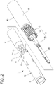
- Fig. 2 is an exploded perspective view of the shield assembly 1 shown in Fig. 1 .
- the braided part connection structure is a braided part connection structure to be used, for example in the shield assembly 1 of a high-frequency connector to be attached to an end of a shielded cable 40.
- the braided part connection structure includes the braided part 50 having a tubular shape that covers an insulated electrical wire 51 in a longitudinal direction, and the shield outer terminal 10 that is a tubular shield member to be electrically connected and fixed to the braided part 50.
- the shielded cable 40 is a coaxial cable including the insulated electrical wire 51 in which a core wire (conductor) 55 is covered with an insulator 53, the tubular braided part 50 covering the insulated electrical wire 51 in the longitudinal direction, and an outer sheath 57 covering the outer periphery of the braided part 50 (see Fig. 2 ).
- the core wire 55 having conductivity may be either a single wire or a twisted wire obtained by twisting a plurality of wires.
- the insulator 53 has an electrical insulation property and covers the core wire 55.
- the shielded cable 40 is a coaxial cable having the braided part 50, but other configurations are not excluded as long as the shielded cable 40 is a cable having the braided part 50.
- the shield assembly 1 is accommodated in an outer housing (not shown) formed of a synthetic resin having an electrical insulation property of a high-frequency connector, and the shield assembly 1 is to be connected to the end of the shielded cable 40.
- the shield assembly 1 according to the present embodiment includes an inner terminal 20, an inner housing 30, and the shield outer terminal (shield member) 10.
- the inner terminal 20 is formed in a tubular shape by a conductive metal, and is to be electrically connected to the core wire 55 of the shielded cable 40 by crimping.
- the inner housing 30 is formed of an electrically insulating synthetic resin, and accommodates and holds the inner terminal 20 in an inner terminal accommodating chamber.
- the shield outer terminal 10 as a shield member according to the present embodiment has an inner housing accommodating chamber which is formed in a cylindrical shape and accommodates the inner housing 30.
- the shield outer terminal 10 is formed by, for example, pressing a conductive metal plate such as copper or a copper alloy.
- one end side of the shield outer terminal 10 being the shield member serves as a fitting end 11, and the fitting end 11 is to be fitted and electrically connected to a shield outer terminal (not shown) which is a shield member of a fitting counterpart.
- the other end side of the shield outer terminal 10 is a braided part connection end 12, and the braided part 50 is to be connected to the braided part connection end 12.
- the shield outer terminal 10 has a braided part joining portion 15 at which a plurality of openings 13 are formed at the braided part connection end 12, which is the other end side of the shield outer terminal 10.
- the openings 13 are formed at intervals along the circumferential direction of the shield outer terminal 10.
- welding portions 17 are formed between the openings 13 adjacent to each other in the circumferential direction.
- the opening 13 of the braided part joining portion 15 is a notched hole having an open end, and the welding portion 17 is a cantilevered protruding piece defined between adjacent notched holes.
- the braided part joining portion 15 is formed in a comb tooth shape over the circumferential direction.
- a width dimension along the circumferential direction of the openings 13 and the welding portions 17 and an interval between adjacent openings 13 and welding portions 17 formed in the braided part joining portion 15 of the shield outer terminal 10 are appropriately set depending on the required strength, the electrical resistance at the time of being connected to the braided part 50, and the like.
- the braided part 50 is formed by braiding wires made of a conductive metal material such as copper or a copper alloy, and is formed in a tubular shape.
- the braided part 50 is provided so as to cover the insulated electrical wire 51 along the longitudinal direction.
- the insulated electrical wire 51 has the core wire 55 at the center of the insulator 53.
- the outer periphery of the braided part 50 is covered with the outer sheath 57, and an end portion of the braided part 50 to be connected to the shield outer terminal 10 is exposed from the outer sheath 57 (see Figs. 1 and 2 ).
- the end portion of the insulated electrical wire 51 is to be inserted into the shield outer terminal 10 at the braided part connection end 12. In this state, the end portion of the braided part 50 covers the braided part joining portion 15 at the braided part connection end 12 of the shield outer terminal 10.
- the braided part 50 covering the braided part joining portion 15 of the shield outer terminal 10 is welded to the welding portion 17 formed of the protruding piece to together form a welding connection portion 25.
- the shield outer terminal 10 and the braided part 50 are electrically connected to each other at the welding connection portion 25 formed by welding the welding portion 17 and the braided part 50.
- Fig. 3 is a perspective view showing a state immediately before the shield outer terminal 10, which is the shield member, and the braided part 50 get connected to each other.
- Fig. 4 is a perspective view showing a state in which the braided part joining portion 15 of the shield outer terminal 10 is covered with the braided part 50.
- Fig. 5A is a longitudinal sectional view showing the state in which the braided part joining portion 15 of the shield outer terminal 10 is covered with the braided part 50
- Fig. 5B is a longitudinal sectional view showing a step of welding the braided part 50 covering the braided part joining portion 15 to the welding portion 17.
- the braided part 50 is loosened, and the braided part 50 is widened in a radial direction so as to form a gap between the braided part 50 and the insulator 53.
- the inner terminal 20 is brought to be accommodated in the inner terminal accommodating chamber of the inner housing 30, and the inner terminal 20, the core wire 55, and the insulator 53 are brought to be inserted into the braided part connection end 12 of the shield outer terminal 10 in order to dispose the braided part joining portion 15 of the shield outer terminal 10 between the braided part 50 and the insulator 53.
- the end portion of the braided part 50 covers the braided part joining portion 15. In this way, the end portion of the braided part 50 is overlapped with the outer peripheral side of the welding portions 17 formed of the plurality of protruding pieces of the braided part joining portion 15.
- a laser irradiation device 100 is used to irradiate a plurality of overlapping portions of the end portion of the braided part 50 which are overlapped with the welding portions 17, with a laser beam 103 to weld the braided part 50 and the welding portions 17 to each other.
- the welding connection portions 25 at which the braided part 50 is welded to the welding portions 17 is formed at the overlapping portions of the welding portions 17 and the braided part 50.
- the braided part joining portion 15 of the braided part connection end 12 of the shield outer terminal 10 and the end portion of the braided part 50 are electrically connected to each other.
- a method for welding the shield outer terminal 10 and the braided part 50 to each other is not limited to laser welding, and various welding methods such as resistance welding or ultrasonic welding may be applied.
- the braided part joining portion 15 of the shield outer terminal 10 and the end portion of the braided part 50 are connected to each other, the braided part joining portion 15 is formed with the openings 13 which are a plurality of notched holes whose end portions are opened to form the welding portions 17 formed of the plurality of protruding pieces. Therefore, the transfer of the thermal energy applied when the braided part 50 is welded to the welding portions 17 to the periphery area thereof is reduced. As a result, the overlapping portions of the welding portions 17 and the braided part 50 can be efficiently welded by the applied thermal energy.
- the braided part 50 covering the braided part joining portion 15 of the shield outer terminal 10 is welded to the welding portions 17 between the plurality of openings 13 formed at intervals along the circumferential direction. Therefore, in the braided part connection structure of the present embodiment, a volume of the welding portion 17 which is a portion of the shield outer terminal 10 to which the braided part 50 is welded is reduced, thereby reducing the heat capacity, and it is possible to prevent the thermal energy applied when the braided part 50 is welded from being transferred to the peripheral area of the welding portion 17 and escaping. As a result, the welding portion 17 of the shield outer terminal 10 and the braided part 50 can be efficiently welded to each other without increasing the output of thermal energy applied for welding.
- the openings 13 formed of notched holes are formed in the end portion of the shield outer terminal 10, and the welding portions 17 formed of the protruding pieces are formed between the openings 13. Therefore, the braided part 50 can be welded by using these protruding pieces as the welding portions 17, and the shield outer terminal 10 and the braided part 50 can be electrically connected to each other.
- the welding portion 17 formed of the cantilevered protruding piece can prevent material yield from decreasing by simultaneously punching out the protruding pieces of a pair of shield outer terminals 10 when the shield outer terminals 10 are formed by pressing metal plates.
- the cylindrical shield outer terminal 10 is exemplified, but the shield outer terminal 10 which is a shield member is not limited to a cylindrical shape, and may be a polygonal cylindrical shape.
- Figs. 6A and 6B are views illustrating a braided part connection structure according to other embodiments of the present invention, in which Fig. 6A is a perspective view of a main part showing a modification of a welding portion 17A in a shield outer terminal 10A, and Fig. 6B is a perspective view of a main part showing a modification of a braided part joining portion 15B in a shield outer terminal 10B.
- the welding portion 17A is formed between openings 13A adjacent to each other in the circumferential direction.
- the opening 13A of the braided part joining portion 15A is a notched hole having an open end
- the welding portion 17A is a cantilevered protruding piece formed between adjacent notched holes. Further, a distal end portion of the protruding piece is bent in a mountain shape protruding toward an outer peripheral side of the shield outer terminal 10A.
- the distal end portion of the welding portion 17A which is a cantilevered protruding piece is bent in a mountain shape, so that a distal end of the welding portion 17A is less likely to be caught when the braided part 50 covers the braided part joining portion 15A, and workability is improved.
- the braided part joining portion 15B of a shield outer terminal 10B is provided in the vicinity of the end portion of the braided part connection end 12 of the shield outer terminal 10B.
- An opening 13B of the braided part joining portion 15B is a through hole formed in the vicinity of the end portion of the shield outer terminal 10B, and the welding portion 17B is a bridge piece formed between adjacent through holes.
- a plurality of openings 13B formed of through holes are formed in the vicinity of the end portion of the shield outer terminal 10B to form a bridge piece between the openings 13B. Therefore, the braided part 50 can be welded using the bridge piece which is made in a form of a double-supported beam having high rigidity as the welding portion 17B, and the welding operation can be stably performed.
- a braided part connection structure includes a braided part (50) having a tubular shape covering an insulated wire (51) along a longitudinal direction of the braided part connection structure and a shield member (for example, a shield outer terminal 10, 10A, 10B) having a tubular shape and electrically connected and fixed to the braided part (50).
- a shield member for example, a shield outer terminal 10, 10A, 10B
- the shield member (for example, the shield outer terminal 10, 10A, 10B) includes a braided part joining portion (15, 15A, 15B) having a plurality of openings (13, 13A, 13B) arranged at intervals along a circumferential direction of the shield member in a portion of the shield member in the longitudinal direction, and a welding portion (17, 17A, 17B) defined by two openings (13, 13A, 13B) adjacent to each other of the plurality of openings (13, 13A, 13B).
- the braided part (50) covers the braided part joining portion (15, 15A, 15B) and is welded to the welding portion (17, 17A, 17B).
- the braided part covering the braided part joining portion of the shield member is welded to the welding portion between the plurality of openings formed at intervals along the circumferential direction. Therefore, in this braided part connection structure, a volume of the welding portion which is a portion of the shield member to which the braided part is to be welded is reduced, thereby reducing the heat capacity, and it is possible to prevent the thermal energy applied when the braided part is welded from being transferred to the peripheral area of the welding portion and escaping. As a result, the welding portion of the shield member and the braided part can be efficiently welded to each other without increasing the output of thermal energy applied for welding.
- the braided part joining portion (15, 15A) may be provided at an end portion of the shield member (for example, the shield outer terminal 10, 10A).
- the plurality of openings (13, 13A) may be notched holes formed at the end portion of the shield member (for example, the shield outer terminal 10, 10A).
- the welding portion (17, 17A) may be a protruding piece formed between two notched holes adjacent to each other of the notched holes.
- the opening formed of the notched hole is formed at the end portion of the shield member, and the cantilevered protruding piece is formed between the openings. Therefore, the braided part can be welded by using the protruding piece as the welding portion, and the shield member and the braided part can be electrically connected to each other.
- the cantilevered protruding piece can prevent material yield from decreasing by simultaneously punching out protruding pieces of a pair of shield members when the shield members are formed by pressing metal plates.
- a distal end portion of the protruding piece may be bent in a convex shape protruding outward in a radial direction of the shield member (for example, the shield outer terminal 10A).
- the distal end portion of the cantilevered protruding piece is bent in a mountain shape, so that a distal end of the protruding piece is less likely to be caught when the braided part covers the braided part joining portion, and workability is improved.
- the braided part joining portion (15B) may be provided in the vicinity of an end portion of the shield member (for example, the shield outer terminal 10B).
- the plurality of openings (13B) may be through holes formed in the vicinity of the end portion of the shield member (for example, the shield outer terminal 10B).
- the welding portion (17B) may be formed of a bridge piece formed between two through holes adjacent to each other of the through holes.
- the openings formed of the through holes are formed in the vicinity of the end portion of the shield member, and the bridge piece is formed between the openings. Therefore, the braided part can be welded using the bridge piece which is made in a form of a double-supported beam having high rigidity as the welding portion, and the welding operation can be stably performed.
Landscapes
- Details Of Connecting Devices For Male And Female Coupling (AREA)
- Insulated Conductors (AREA)
- Shielding Devices Or Components To Electric Or Magnetic Fields (AREA)
- Connections Effected By Soldering, Adhesion, Or Permanent Deformation (AREA)
Abstract
Description
- The present invention relates to a braided part connection structure.
- In a related art shield connection structure, an outer ring is attached to an outer periphery of a shield braided wire (braided part) covering an outer periphery of a shielded electric cable, and overlapping portions of the outer ring and the shield braided wire are joined by spot welding by means of laser welding or resistance welding at a plurality of positions in a circumferential direction (see, for example,
JPH11-509672A - When the overlapping portion of the outer ring and the shield braided wire is subjected to the spot welding, thermal energy is transmitted from a welded portion to the outer ring or the like and escapes. For this reason, it is necessary to increase the output of the laser and the electric power for welding, and there is a problem that the efficiency is lowered.
- Illustrative aspects of the present invention provide a braided part connection structure configured to efficiently weld and connect a shield member and a braided part to each other.
- According to an illustrative aspect of the present invention, a braided part connection structure includes a braided part having a tubular shape covering an insulated wire along a longitudinal direction of the braided part connection structure and a shield member having a tubular shape and electrically connected and fixed to the braided part. The shield member includes a braided part joining portion having a plurality of openings arranged at intervals along a circumferential direction of the shield member in a portion of the shield member in the longitudinal direction, and a welding portion defined by two openings adjacent to each other of the plurality of openings. The braided part covers the braided part joining portion and is welded to the welding portion.
- Other aspects and advantages of the invention will be apparent from the following description, the drawings and the claims.
-
-
Fig. 1 is a view illustrating a braided part connection structure according to an embodiment of the present invention, and is showing a perspective view and an enlarged view of a main part showing a state in which a shield member and a braided part in a shield assembly are connected to each other; -
Fig. 2 is an exploded perspective view of the shield assembly shown inFig. 1 ; -
Fig. 3 is a perspective view showing a state immediately before the shield member and the braided part get connected to each other; -
Fig. 4 is a perspective view showing a state in which a braided part joining portion of the shield member is covered with the braided part; -
Fig. 5A is a longitudinal sectional view showing the state in which the braided part joining portion of the shield member is covered with the braided part, andFig. 5B is a longitudinal sectional view showing a step of welding the braided part covering the braided part joining portion to a welding portion; and -
Figs. 6A and 6B are views illustrating a braided part connection structure according to other embodiments of the present invention, in whichFig. 6A is a perspective view of a main part showing a modification of a welding portion in a shield member, andFig. 6B is a perspective view of a main part showing a modification of a braided part joining portion in a shield member. - Hereinafter, embodiments of the invention will be described with reference to the drawings.
Fig. 1 is a view illustrating a braided part connection structure according to an embodiment of the present invention, and is showing a perspective view and an enlarged view of a main part showing a state in which a shield outer terminal (shield member) 10 and abraided part 50 in ashield assembly 1 are connected to each other.Fig. 2 is an exploded perspective view of theshield assembly 1 shown inFig. 1 . - As shown in
Figs. 1 and2 , the braided part connection structure according to the present embodiment is a braided part connection structure to be used, for example in theshield assembly 1 of a high-frequency connector to be attached to an end of a shieldedcable 40. The braided part connection structure includes thebraided part 50 having a tubular shape that covers an insulatedelectrical wire 51 in a longitudinal direction, and the shieldouter terminal 10 that is a tubular shield member to be electrically connected and fixed to thebraided part 50. - The shielded
cable 40 is a coaxial cable including the insulatedelectrical wire 51 in which a core wire (conductor) 55 is covered with aninsulator 53, the tubular braidedpart 50 covering the insulatedelectrical wire 51 in the longitudinal direction, and anouter sheath 57 covering the outer periphery of the braided part 50 (seeFig. 2 ). Thecore wire 55 having conductivity may be either a single wire or a twisted wire obtained by twisting a plurality of wires. Theinsulator 53 has an electrical insulation property and covers thecore wire 55. In the present embodiment, the shieldedcable 40 is a coaxial cable having thebraided part 50, but other configurations are not excluded as long as the shieldedcable 40 is a cable having thebraided part 50. - The
shield assembly 1 is accommodated in an outer housing (not shown) formed of a synthetic resin having an electrical insulation property of a high-frequency connector, and theshield assembly 1 is to be connected to the end of the shieldedcable 40. Theshield assembly 1 according to the present embodiment includes aninner terminal 20, aninner housing 30, and the shield outer terminal (shield member) 10. - The
inner terminal 20 is formed in a tubular shape by a conductive metal, and is to be electrically connected to thecore wire 55 of the shieldedcable 40 by crimping. Theinner housing 30 is formed of an electrically insulating synthetic resin, and accommodates and holds theinner terminal 20 in an inner terminal accommodating chamber. - The shield
outer terminal 10 as a shield member according to the present embodiment has an inner housing accommodating chamber which is formed in a cylindrical shape and accommodates theinner housing 30. The shieldouter terminal 10 is formed by, for example, pressing a conductive metal plate such as copper or a copper alloy. As shown inFig. 2 , one end side of the shieldouter terminal 10 being the shield member serves as a fitting end 11, and the fitting end 11 is to be fitted and electrically connected to a shield outer terminal (not shown) which is a shield member of a fitting counterpart. The other end side of the shieldouter terminal 10 is a braidedpart connection end 12, and thebraided part 50 is to be connected to the braidedpart connection end 12. - As shown in
Fig. 2 , the shieldouter terminal 10 has a braidedpart joining portion 15 at which a plurality ofopenings 13 are formed at the braidedpart connection end 12, which is the other end side of the shieldouter terminal 10. Theopenings 13 are formed at intervals along the circumferential direction of the shieldouter terminal 10. In the braidedpart joining portion 15,welding portions 17 are formed between theopenings 13 adjacent to each other in the circumferential direction. In the present embodiment, the opening 13 of the braidedpart joining portion 15 is a notched hole having an open end, and thewelding portion 17 is a cantilevered protruding piece defined between adjacent notched holes. As a result, the braidedpart joining portion 15 is formed in a comb tooth shape over the circumferential direction. A width dimension along the circumferential direction of theopenings 13 and thewelding portions 17 and an interval betweenadjacent openings 13 andwelding portions 17 formed in the braidedpart joining portion 15 of the shieldouter terminal 10 are appropriately set depending on the required strength, the electrical resistance at the time of being connected to thebraided part 50, and the like. - The
braided part 50 is formed by braiding wires made of a conductive metal material such as copper or a copper alloy, and is formed in a tubular shape. The braidedpart 50 is provided so as to cover the insulatedelectrical wire 51 along the longitudinal direction. The insulatedelectrical wire 51 has thecore wire 55 at the center of theinsulator 53. The outer periphery of thebraided part 50 is covered with theouter sheath 57, and an end portion of thebraided part 50 to be connected to the shieldouter terminal 10 is exposed from the outer sheath 57 (seeFigs. 1 and2 ). - The end portion of the insulated
electrical wire 51 is to be inserted into the shieldouter terminal 10 at the braidedpart connection end 12. In this state, the end portion of thebraided part 50 covers the braidedpart joining portion 15 at the braidedpart connection end 12 of the shieldouter terminal 10. - The
braided part 50 covering the braidedpart joining portion 15 of the shieldouter terminal 10 is welded to thewelding portion 17 formed of the protruding piece to together form awelding connection portion 25. The shieldouter terminal 10 and thebraided part 50 are electrically connected to each other at thewelding connection portion 25 formed by welding thewelding portion 17 and thebraided part 50. - Next, how the
braided part 50 gets connected to the shieldouter terminal 10, which is the shield member, will be described.Fig. 3 is a perspective view showing a state immediately before the shieldouter terminal 10, which is the shield member, and thebraided part 50 get connected to each other.Fig. 4 is a perspective view showing a state in which the braidedpart joining portion 15 of the shieldouter terminal 10 is covered with thebraided part 50.Fig. 5A is a longitudinal sectional view showing the state in which the braidedpart joining portion 15 of the shieldouter terminal 10 is covered with thebraided part 50, andFig. 5B is a longitudinal sectional view showing a step of welding the braidedpart 50 covering the braidedpart joining portion 15 to thewelding portion 17. - First, as shown in
Fig. 3 , thebraided part 50 is loosened, and thebraided part 50 is widened in a radial direction so as to form a gap between thebraided part 50 and theinsulator 53. Next, theinner terminal 20 is brought to be accommodated in the inner terminal accommodating chamber of theinner housing 30, and theinner terminal 20, thecore wire 55, and theinsulator 53 are brought to be inserted into the braidedpart connection end 12 of the shieldouter terminal 10 in order to dispose the braidedpart joining portion 15 of the shieldouter terminal 10 between thebraided part 50 and theinsulator 53. Then, as shown inFigs. 4 and5A , the end portion of thebraided part 50 covers the braidedpart joining portion 15. In this way, the end portion of thebraided part 50 is overlapped with the outer peripheral side of thewelding portions 17 formed of the plurality of protruding pieces of the braidedpart joining portion 15. - Next, as shown in
Fig. 5B , alaser irradiation device 100 is used to irradiate a plurality of overlapping portions of the end portion of thebraided part 50 which are overlapped with thewelding portions 17, with alaser beam 103 to weld thebraided part 50 and thewelding portions 17 to each other. Then, thewelding connection portions 25 at which thebraided part 50 is welded to thewelding portions 17 is formed at the overlapping portions of thewelding portions 17 and thebraided part 50. As a result, the braidedpart joining portion 15 of the braided part connection end 12 of the shieldouter terminal 10 and the end portion of thebraided part 50 are electrically connected to each other. A method for welding the shieldouter terminal 10 and thebraided part 50 to each other is not limited to laser welding, and various welding methods such as resistance welding or ultrasonic welding may be applied. - Here, when the braided
part joining portion 15 of the shieldouter terminal 10 and the end portion of thebraided part 50 are connected to each other, the braidedpart joining portion 15 is formed with theopenings 13 which are a plurality of notched holes whose end portions are opened to form thewelding portions 17 formed of the plurality of protruding pieces. Therefore, the transfer of the thermal energy applied when thebraided part 50 is welded to thewelding portions 17 to the periphery area thereof is reduced. As a result, the overlapping portions of thewelding portions 17 and thebraided part 50 can be efficiently welded by the applied thermal energy. - As described above, according to the braided part connection structure of the present embodiment, the
braided part 50 covering the braidedpart joining portion 15 of the shieldouter terminal 10 is welded to thewelding portions 17 between the plurality ofopenings 13 formed at intervals along the circumferential direction. Therefore, in the braided part connection structure of the present embodiment, a volume of thewelding portion 17 which is a portion of the shield outer terminal 10 to which thebraided part 50 is welded is reduced, thereby reducing the heat capacity, and it is possible to prevent the thermal energy applied when thebraided part 50 is welded from being transferred to the peripheral area of thewelding portion 17 and escaping. As a result, thewelding portion 17 of the shieldouter terminal 10 and thebraided part 50 can be efficiently welded to each other without increasing the output of thermal energy applied for welding. - Further, the
openings 13 formed of notched holes are formed in the end portion of the shieldouter terminal 10, and thewelding portions 17 formed of the protruding pieces are formed between theopenings 13. Therefore, thebraided part 50 can be welded by using these protruding pieces as thewelding portions 17, and the shieldouter terminal 10 and thebraided part 50 can be electrically connected to each other. In addition, thewelding portion 17 formed of the cantilevered protruding piece can prevent material yield from decreasing by simultaneously punching out the protruding pieces of a pair of shieldouter terminals 10 when the shieldouter terminals 10 are formed by pressing metal plates. - In the above embodiment, the cylindrical shield
outer terminal 10 is exemplified, but the shieldouter terminal 10 which is a shield member is not limited to a cylindrical shape, and may be a polygonal cylindrical shape. -
Figs. 6A and 6B are views illustrating a braided part connection structure according to other embodiments of the present invention, in whichFig. 6A is a perspective view of a main part showing a modification of awelding portion 17A in a shieldouter terminal 10A, andFig. 6B is a perspective view of a main part showing a modification of a braidedpart joining portion 15B in a shieldouter terminal 10B. As shown inFig. 6B , in a braidedpart joining portion 15A of the shieldouter terminal 10A, thewelding portion 17A is formed betweenopenings 13A adjacent to each other in the circumferential direction. Theopening 13A of the braidedpart joining portion 15A is a notched hole having an open end, and thewelding portion 17A is a cantilevered protruding piece formed between adjacent notched holes. Further, a distal end portion of the protruding piece is bent in a mountain shape protruding toward an outer peripheral side of the shieldouter terminal 10A. - Therefore, according to the braided part connection structure of the present embodiment, the distal end portion of the
welding portion 17A which is a cantilevered protruding piece is bent in a mountain shape, so that a distal end of thewelding portion 17A is less likely to be caught when thebraided part 50 covers the braidedpart joining portion 15A, and workability is improved. - As shown in
Fig. 6B , the braidedpart joining portion 15B of a shieldouter terminal 10B is provided in the vicinity of the end portion of the braided part connection end 12 of the shieldouter terminal 10B. Anopening 13B of the braidedpart joining portion 15B is a through hole formed in the vicinity of the end portion of the shieldouter terminal 10B, and thewelding portion 17B is a bridge piece formed between adjacent through holes. - Therefore, according to the braided part connection structure of the present embodiment, a plurality of
openings 13B formed of through holes are formed in the vicinity of the end portion of the shield outer terminal 10B to form a bridge piece between theopenings 13B. Therefore, thebraided part 50 can be welded using the bridge piece which is made in a form of a double-supported beam having high rigidity as thewelding portion 17B, and the welding operation can be stably performed. - While the present invention has been described with reference to certain exemplary embodiments thereof, the scope of the present invention is not limited to the exemplary embodiments described above, and it will be understood by those skilled in the art that various changes and modifications may be made therein without departing from the scope of the present invention as defined by the appended claims.
- According to an aspect of the embodiments described above, a braided part connection structure includes a braided part (50) having a tubular shape covering an insulated wire (51) along a longitudinal direction of the braided part connection structure and a shield member (for example, a shield
outer terminal outer terminal - According to the braided part connection structure having the above configuration, the braided part covering the braided part joining portion of the shield member is welded to the welding portion between the plurality of openings formed at intervals along the circumferential direction. Therefore, in this braided part connection structure, a volume of the welding portion which is a portion of the shield member to which the braided part is to be welded is reduced, thereby reducing the heat capacity, and it is possible to prevent the thermal energy applied when the braided part is welded from being transferred to the peripheral area of the welding portion and escaping. As a result, the welding portion of the shield member and the braided part can be efficiently welded to each other without increasing the output of thermal energy applied for welding.
- The braided part joining portion (15, 15A) may be provided at an end portion of the shield member (for example, the shield
outer terminal outer terminal - With this configuration, the opening formed of the notched hole is formed at the end portion of the shield member, and the cantilevered protruding piece is formed between the openings. Therefore, the braided part can be welded by using the protruding piece as the welding portion, and the shield member and the braided part can be electrically connected to each other. In addition, for example, the cantilevered protruding piece can prevent material yield from decreasing by simultaneously punching out protruding pieces of a pair of shield members when the shield members are formed by pressing metal plates.
- A distal end portion of the protruding piece may be bent in a convex shape protruding outward in a radial direction of the shield member (for example, the shield outer terminal 10A).
- With this configuration, the distal end portion of the cantilevered protruding piece is bent in a mountain shape, so that a distal end of the protruding piece is less likely to be caught when the braided part covers the braided part joining portion, and workability is improved.
- The braided part joining portion (15B) may be provided in the vicinity of an end portion of the shield member (for example, the shield outer terminal 10B). The plurality of openings (13B) may be through holes formed in the vicinity of the end portion of the shield member (for example, the shield outer terminal 10B). The welding portion (17B) may be formed of a bridge piece formed between two through holes adjacent to each other of the through holes.
- With this configuration, the openings formed of the through holes are formed in the vicinity of the end portion of the shield member, and the bridge piece is formed between the openings. Therefore, the braided part can be welded using the bridge piece which is made in a form of a double-supported beam having high rigidity as the welding portion, and the welding operation can be stably performed.
Claims (4)
- A braided part connection structure comprising:a braided part having a tubular shape covering an insulated wire along a longitudinal direction of the braided part connection structure; anda shield member having a tubular shape and electrically connected and fixed to the braided part,wherein the shield member includes a braided part joining portion having a plurality of openings arranged at intervals along a circumferential direction of the shield member in a portion of the shield member in the longitudinal direction, and a welding portion defined by two openings adjacent to each other of the plurality of openings, andwherein the braided part covers the braided part joining portion and is welded to the welding portion.
- The braided part connection structure according to claim 1,wherein the braided part joining portion is provided at an end portion of the shield member,wherein the plurality of openings are notched holes formed at the end portion of the shield member, andwherein the welding portion is a protruding piece formed between two notched holes adjacent to each other of the notched holes.
- The braided part connection structure according to claim 2,
wherein a distal end portion of the protruding piece is bent in a convex shape protruding outward in a radial direction of the shield member. - The braided part connection structure according to claim 1,wherein the braided part joining portion is provided in the vicinity of an end portion of the shield member,wherein the plurality of openings are through holes formed in the vicinity of the end portion of the shield member, andwherein the welding portion is formed of a bridge piece formed between two through holes adjacent to each other of the through holes.
Applications Claiming Priority (1)
| Application Number | Priority Date | Filing Date | Title |
|---|---|---|---|
| JP2020210715A JP7261215B6 (en) | 2020-12-18 | 2020-12-18 | braided connection structure |
Publications (2)
| Publication Number | Publication Date |
|---|---|
| EP4016744A1 true EP4016744A1 (en) | 2022-06-22 |
| EP4016744B1 EP4016744B1 (en) | 2023-05-10 |
Family
ID=79230647
Family Applications (1)
| Application Number | Title | Priority Date | Filing Date |
|---|---|---|---|
| EP21213310.2A Active EP4016744B1 (en) | 2020-12-18 | 2021-12-09 | Braided part connection structure |
Country Status (4)
| Country | Link |
|---|---|
| US (1) | US11949196B2 (en) |
| EP (1) | EP4016744B1 (en) |
| JP (1) | JP7261215B6 (en) |
| CN (1) | CN114649694B (en) |
Cited By (1)
| Publication number | Priority date | Publication date | Assignee | Title |
|---|---|---|---|---|
| WO2025040999A1 (en) * | 2023-08-18 | 2025-02-27 | Tyco Electronics (Shanghai) Co., Ltd. | Terminal assembly, connector, male connector, female connector and connector assembly |
Citations (6)
| Publication number | Priority date | Publication date | Assignee | Title |
|---|---|---|---|---|
| US5195910A (en) * | 1990-01-16 | 1993-03-23 | Nec Corporation | Coaxial connector |
| EP1143572A2 (en) * | 2000-04-07 | 2001-10-10 | Spinner GmbH Elektrotechnische Fabrik | Coaxial connector |
| EP2219267A1 (en) * | 2009-02-13 | 2010-08-18 | Alcatel Lucent | Manufacturing method for a connection between a coaxial cable and a coaxial connector and a coaxial cable with a terminating coaxial connector thereof |
| US20140113486A1 (en) * | 2012-10-11 | 2014-04-24 | John Mezzalingua Associates, LLC | Coaxial cable device and method involving weld and mate connectivity |
| EP2761699A1 (en) * | 2011-09-27 | 2014-08-06 | Yazaki Corporation | Braid and wire harness |
| CN211700674U (en) * | 2020-03-10 | 2020-10-16 | 江苏华兴通讯科技有限公司 | High standing wave performance bending connector |
Family Cites Families (18)
| Publication number | Priority date | Publication date | Assignee | Title |
|---|---|---|---|---|
| FR2642571B1 (en) * | 1989-01-30 | 1993-04-23 | Cegelec | CONNECTION ARRANGEMENT FOR COAXIAL CABLE AND CORRESPONDING CONNECTION MODULE, IN PARTICULAR JUNCTION BLOCK |
| KR100382584B1 (en) | 1995-07-19 | 2003-10-11 | 더 휘태커 코포레이션 | Shielded connection structure and connection method and shielded electrical connector |
| JP3435032B2 (en) * | 1997-08-29 | 2003-08-11 | 矢崎総業株式会社 | Connection structure and processing method of shielded electric wire |
| JP3394175B2 (en) * | 1998-01-13 | 2003-04-07 | 矢崎総業株式会社 | Termination treatment structure and termination treatment method for shielded wires |
| JP3281597B2 (en) * | 1998-03-10 | 2002-05-13 | 株式会社オートネットワーク技術研究所 | Termination structure of shielded wires |
| JP3947096B2 (en) * | 2002-11-26 | 2007-07-18 | 株式会社オートネットワーク技術研究所 | Conductive path and shield member with shield function |
| DE102006006845B3 (en) * | 2006-02-15 | 2007-07-19 | Tyco Electronics Amp Gmbh | Electrical outer conductor sleeve for e.g. electrical angular -plug-in connector, has spring segment unilaterally connected with wall in single piece, where free longitudinal end section of segment partially protrudes inwardly into sleeve |
| JP4744419B2 (en) * | 2006-11-10 | 2011-08-10 | 矢崎総業株式会社 | Shield terminal processing method and shield terminal processing structure |
| JP2009272128A (en) * | 2008-05-07 | 2009-11-19 | Autonetworks Technologies Ltd | Shield connector device |
| JP5298934B2 (en) | 2009-02-24 | 2013-09-25 | 株式会社オートネットワーク技術研究所 | Shield connector |
| JP5293644B2 (en) * | 2010-03-02 | 2013-09-18 | 住友電装株式会社 | Wiring harness wiring structure |
| US8636529B2 (en) * | 2011-02-17 | 2014-01-28 | Corning Gilbert Inc. | Blind mate interconnect and contact |
| JP5664925B2 (en) | 2011-10-12 | 2015-02-04 | 住友電装株式会社 | Shield shell and shield connector |
| DE102012000137B4 (en) * | 2012-01-06 | 2013-08-22 | Auto-Kabel Managementgesellschaft Mbh | Electric cable, method for producing an electric cable, and welding device for producing an electric cable |
| JP5772710B2 (en) | 2012-05-11 | 2015-09-02 | 日立金属株式会社 | Connection structure, connection method, and cable for multi-core differential signal transmission |
| DE102012105258A1 (en) | 2012-06-18 | 2013-12-19 | Tyco Electronics Amp Gmbh | Umbrella sleeve and Abschirmendelement comprising a shielding sleeve |
| US10008307B1 (en) * | 2016-11-10 | 2018-06-26 | Superior Essex International LP | High frequency shielded communications cables |
| WO2019210112A1 (en) * | 2018-04-25 | 2019-10-31 | Ppc Broadband, Inc. | Coaxial cable connectors having port grounding |
-
2020
- 2020-12-18 JP JP2020210715A patent/JP7261215B6/en active Active
-
2021
- 2021-12-09 EP EP21213310.2A patent/EP4016744B1/en active Active
- 2021-12-16 CN CN202111542714.1A patent/CN114649694B/en active Active
- 2021-12-17 US US17/554,104 patent/US11949196B2/en active Active
Patent Citations (6)
| Publication number | Priority date | Publication date | Assignee | Title |
|---|---|---|---|---|
| US5195910A (en) * | 1990-01-16 | 1993-03-23 | Nec Corporation | Coaxial connector |
| EP1143572A2 (en) * | 2000-04-07 | 2001-10-10 | Spinner GmbH Elektrotechnische Fabrik | Coaxial connector |
| EP2219267A1 (en) * | 2009-02-13 | 2010-08-18 | Alcatel Lucent | Manufacturing method for a connection between a coaxial cable and a coaxial connector and a coaxial cable with a terminating coaxial connector thereof |
| EP2761699A1 (en) * | 2011-09-27 | 2014-08-06 | Yazaki Corporation | Braid and wire harness |
| US20140113486A1 (en) * | 2012-10-11 | 2014-04-24 | John Mezzalingua Associates, LLC | Coaxial cable device and method involving weld and mate connectivity |
| CN211700674U (en) * | 2020-03-10 | 2020-10-16 | 江苏华兴通讯科技有限公司 | High standing wave performance bending connector |
Cited By (1)
| Publication number | Priority date | Publication date | Assignee | Title |
|---|---|---|---|---|
| WO2025040999A1 (en) * | 2023-08-18 | 2025-02-27 | Tyco Electronics (Shanghai) Co., Ltd. | Terminal assembly, connector, male connector, female connector and connector assembly |
Also Published As
| Publication number | Publication date |
|---|---|
| JP7261215B6 (en) | 2023-05-10 |
| EP4016744B1 (en) | 2023-05-10 |
| CN114649694B (en) | 2024-01-30 |
| US20220200170A1 (en) | 2022-06-23 |
| JP7261215B2 (en) | 2023-04-19 |
| CN114649694A (en) | 2022-06-21 |
| US11949196B2 (en) | 2024-04-02 |
| JP2022097246A (en) | 2022-06-30 |
Similar Documents
| Publication | Publication Date | Title |
|---|---|---|
| JP6358807B2 (en) | Cable assembly | |
| US9161482B2 (en) | Shield terminal connection structure and method | |
| JP5557604B2 (en) | Braided wire processing method and ring member | |
| GB2330021A (en) | Connecting terminal to braid of shielded wire | |
| JP3435032B2 (en) | Connection structure and processing method of shielded electric wire | |
| CN112821099B (en) | Connecting device and wire connecting structure | |
| JP7273006B2 (en) | Electric wire manufacturing method with terminal, and electric wire with terminal | |
| US20150104983A1 (en) | Joint structure between end of coaxial cable and terminal, and joining method therebetween | |
| EP4016744B1 (en) | Braided part connection structure | |
| GB2332992A (en) | Sealing the braid of a coaxial cable | |
| US5967855A (en) | Connection structure for shield electric cable and method of processing shield electric cable | |
| JP3517155B2 (en) | Shield wire connection structure and shield terminal connection method | |
| KR20210015688A (en) | Intermediate product and method for crimping an electrical conductor | |
| JP3901855B2 (en) | Shield terminal | |
| EP4068518B1 (en) | Braided part connection structure | |
| CN115117647B (en) | Electric wire with terminal | |
| US6477769B2 (en) | Method for assembling a controlled impedance connector | |
| JP2017004844A (en) | Electric wire with terminal and manufacturing method thereof | |
| JP2023170102A (en) | Wire welding method | |
| JP2013254701A (en) | Coaxial cable and coaxial cable unit | |
| JP2024041218A (en) | Terminals and wires with terminals | |
| JP2012120371A (en) | Terminal structure of coaxial cable and connection structure of terminal of the coaxial cable | |
| GB2349019A (en) | Connecting grounding wire to braid of shielded wire |
Legal Events
| Date | Code | Title | Description |
|---|---|---|---|
| PUAI | Public reference made under article 153(3) epc to a published international application that has entered the european phase |
Free format text: ORIGINAL CODE: 0009012 |
|
| STAA | Information on the status of an ep patent application or granted ep patent |
Free format text: STATUS: REQUEST FOR EXAMINATION WAS MADE |
|
| 17P | Request for examination filed |
Effective date: 20211209 |
|
| AK | Designated contracting states |
Kind code of ref document: A1 Designated state(s): AL AT BE BG CH CY CZ DE DK EE ES FI FR GB GR HR HU IE IS IT LI LT LU LV MC MK MT NL NO PL PT RO RS SE SI SK SM TR |
|
| STAA | Information on the status of an ep patent application or granted ep patent |
Free format text: STATUS: EXAMINATION IS IN PROGRESS |
|
| 17Q | First examination report despatched |
Effective date: 20220928 |
|
| GRAP | Despatch of communication of intention to grant a patent |
Free format text: ORIGINAL CODE: EPIDOSNIGR1 |
|
| STAA | Information on the status of an ep patent application or granted ep patent |
Free format text: STATUS: GRANT OF PATENT IS INTENDED |
|
| INTG | Intention to grant announced |
Effective date: 20230221 |
|
| GRAS | Grant fee paid |
Free format text: ORIGINAL CODE: EPIDOSNIGR3 |
|
| GRAA | (expected) grant |
Free format text: ORIGINAL CODE: 0009210 |
|
| STAA | Information on the status of an ep patent application or granted ep patent |
Free format text: STATUS: THE PATENT HAS BEEN GRANTED |
|
| AK | Designated contracting states |
Kind code of ref document: B1 Designated state(s): AL AT BE BG CH CY CZ DE DK EE ES FI FR GB GR HR HU IE IS IT LI LT LU LV MC MK MT NL NO PL PT RO RS SE SI SK SM TR |
|
| REG | Reference to a national code |
Ref country code: GB Ref legal event code: FG4D |
|
| REG | Reference to a national code |
Ref country code: AT Ref legal event code: REF Ref document number: 1567653 Country of ref document: AT Kind code of ref document: T Effective date: 20230515 Ref country code: CH Ref legal event code: EP |
|
| REG | Reference to a national code |
Ref country code: DE Ref legal event code: R096 Ref document number: 602021002334 Country of ref document: DE |
|
| RAP4 | Party data changed (patent owner data changed or rights of a patent transferred) |
Owner name: YAZAKI CORPORATION |
|
| REG | Reference to a national code |
Ref country code: IE Ref legal event code: FG4D |
|
| REG | Reference to a national code |
Ref country code: LT Ref legal event code: MG9D |
|
| REG | Reference to a national code |
Ref country code: NL Ref legal event code: MP Effective date: 20230510 |
|
| REG | Reference to a national code |
Ref country code: AT Ref legal event code: MK05 Ref document number: 1567653 Country of ref document: AT Kind code of ref document: T Effective date: 20230510 |
|
| PG25 | Lapsed in a contracting state [announced via postgrant information from national office to epo] |
Ref country code: SE Free format text: LAPSE BECAUSE OF FAILURE TO SUBMIT A TRANSLATION OF THE DESCRIPTION OR TO PAY THE FEE WITHIN THE PRESCRIBED TIME-LIMIT Effective date: 20230510 Ref country code: PT Free format text: LAPSE BECAUSE OF FAILURE TO SUBMIT A TRANSLATION OF THE DESCRIPTION OR TO PAY THE FEE WITHIN THE PRESCRIBED TIME-LIMIT Effective date: 20230911 Ref country code: NO Free format text: LAPSE BECAUSE OF FAILURE TO SUBMIT A TRANSLATION OF THE DESCRIPTION OR TO PAY THE FEE WITHIN THE PRESCRIBED TIME-LIMIT Effective date: 20230810 Ref country code: NL Free format text: LAPSE BECAUSE OF FAILURE TO SUBMIT A TRANSLATION OF THE DESCRIPTION OR TO PAY THE FEE WITHIN THE PRESCRIBED TIME-LIMIT Effective date: 20230510 Ref country code: ES Free format text: LAPSE BECAUSE OF FAILURE TO SUBMIT A TRANSLATION OF THE DESCRIPTION OR TO PAY THE FEE WITHIN THE PRESCRIBED TIME-LIMIT Effective date: 20230510 Ref country code: AT Free format text: LAPSE BECAUSE OF FAILURE TO SUBMIT A TRANSLATION OF THE DESCRIPTION OR TO PAY THE FEE WITHIN THE PRESCRIBED TIME-LIMIT Effective date: 20230510 |
|
| PG25 | Lapsed in a contracting state [announced via postgrant information from national office to epo] |
Ref country code: RS Free format text: LAPSE BECAUSE OF FAILURE TO SUBMIT A TRANSLATION OF THE DESCRIPTION OR TO PAY THE FEE WITHIN THE PRESCRIBED TIME-LIMIT Effective date: 20230510 Ref country code: PL Free format text: LAPSE BECAUSE OF FAILURE TO SUBMIT A TRANSLATION OF THE DESCRIPTION OR TO PAY THE FEE WITHIN THE PRESCRIBED TIME-LIMIT Effective date: 20230510 Ref country code: LV Free format text: LAPSE BECAUSE OF FAILURE TO SUBMIT A TRANSLATION OF THE DESCRIPTION OR TO PAY THE FEE WITHIN THE PRESCRIBED TIME-LIMIT Effective date: 20230510 Ref country code: LT Free format text: LAPSE BECAUSE OF FAILURE TO SUBMIT A TRANSLATION OF THE DESCRIPTION OR TO PAY THE FEE WITHIN THE PRESCRIBED TIME-LIMIT Effective date: 20230510 Ref country code: IS Free format text: LAPSE BECAUSE OF FAILURE TO SUBMIT A TRANSLATION OF THE DESCRIPTION OR TO PAY THE FEE WITHIN THE PRESCRIBED TIME-LIMIT Effective date: 20230910 Ref country code: HR Free format text: LAPSE BECAUSE OF FAILURE TO SUBMIT A TRANSLATION OF THE DESCRIPTION OR TO PAY THE FEE WITHIN THE PRESCRIBED TIME-LIMIT Effective date: 20230510 Ref country code: GR Free format text: LAPSE BECAUSE OF FAILURE TO SUBMIT A TRANSLATION OF THE DESCRIPTION OR TO PAY THE FEE WITHIN THE PRESCRIBED TIME-LIMIT Effective date: 20230811 |
|
| PG25 | Lapsed in a contracting state [announced via postgrant information from national office to epo] |
Ref country code: FI Free format text: LAPSE BECAUSE OF FAILURE TO SUBMIT A TRANSLATION OF THE DESCRIPTION OR TO PAY THE FEE WITHIN THE PRESCRIBED TIME-LIMIT Effective date: 20230510 |
|
| PG25 | Lapsed in a contracting state [announced via postgrant information from national office to epo] |
Ref country code: SK Free format text: LAPSE BECAUSE OF FAILURE TO SUBMIT A TRANSLATION OF THE DESCRIPTION OR TO PAY THE FEE WITHIN THE PRESCRIBED TIME-LIMIT Effective date: 20230510 |
|
| PG25 | Lapsed in a contracting state [announced via postgrant information from national office to epo] |
Ref country code: SM Free format text: LAPSE BECAUSE OF FAILURE TO SUBMIT A TRANSLATION OF THE DESCRIPTION OR TO PAY THE FEE WITHIN THE PRESCRIBED TIME-LIMIT Effective date: 20230510 Ref country code: SK Free format text: LAPSE BECAUSE OF FAILURE TO SUBMIT A TRANSLATION OF THE DESCRIPTION OR TO PAY THE FEE WITHIN THE PRESCRIBED TIME-LIMIT Effective date: 20230510 Ref country code: RO Free format text: LAPSE BECAUSE OF FAILURE TO SUBMIT A TRANSLATION OF THE DESCRIPTION OR TO PAY THE FEE WITHIN THE PRESCRIBED TIME-LIMIT Effective date: 20230510 Ref country code: EE Free format text: LAPSE BECAUSE OF FAILURE TO SUBMIT A TRANSLATION OF THE DESCRIPTION OR TO PAY THE FEE WITHIN THE PRESCRIBED TIME-LIMIT Effective date: 20230510 Ref country code: DK Free format text: LAPSE BECAUSE OF FAILURE TO SUBMIT A TRANSLATION OF THE DESCRIPTION OR TO PAY THE FEE WITHIN THE PRESCRIBED TIME-LIMIT Effective date: 20230510 Ref country code: CZ Free format text: LAPSE BECAUSE OF FAILURE TO SUBMIT A TRANSLATION OF THE DESCRIPTION OR TO PAY THE FEE WITHIN THE PRESCRIBED TIME-LIMIT Effective date: 20230510 |
|
| REG | Reference to a national code |
Ref country code: DE Ref legal event code: R097 Ref document number: 602021002334 Country of ref document: DE |
|
| PLBE | No opposition filed within time limit |
Free format text: ORIGINAL CODE: 0009261 |
|
| STAA | Information on the status of an ep patent application or granted ep patent |
Free format text: STATUS: NO OPPOSITION FILED WITHIN TIME LIMIT |
|
| 26N | No opposition filed |
Effective date: 20240213 |
|
| PG25 | Lapsed in a contracting state [announced via postgrant information from national office to epo] |
Ref country code: SI Free format text: LAPSE BECAUSE OF FAILURE TO SUBMIT A TRANSLATION OF THE DESCRIPTION OR TO PAY THE FEE WITHIN THE PRESCRIBED TIME-LIMIT Effective date: 20230510 |
|
| PG25 | Lapsed in a contracting state [announced via postgrant information from national office to epo] |
Ref country code: SI Free format text: LAPSE BECAUSE OF FAILURE TO SUBMIT A TRANSLATION OF THE DESCRIPTION OR TO PAY THE FEE WITHIN THE PRESCRIBED TIME-LIMIT Effective date: 20230510 Ref country code: IT Free format text: LAPSE BECAUSE OF FAILURE TO SUBMIT A TRANSLATION OF THE DESCRIPTION OR TO PAY THE FEE WITHIN THE PRESCRIBED TIME-LIMIT Effective date: 20230510 |
|
| PG25 | Lapsed in a contracting state [announced via postgrant information from national office to epo] |
Ref country code: LU Free format text: LAPSE BECAUSE OF NON-PAYMENT OF DUE FEES Effective date: 20231209 |
|
| PG25 | Lapsed in a contracting state [announced via postgrant information from national office to epo] |
Ref country code: MC Free format text: LAPSE BECAUSE OF FAILURE TO SUBMIT A TRANSLATION OF THE DESCRIPTION OR TO PAY THE FEE WITHIN THE PRESCRIBED TIME-LIMIT Effective date: 20230510 |
|
| REG | Reference to a national code |
Ref country code: BE Ref legal event code: MM Effective date: 20231231 |
|
| PG25 | Lapsed in a contracting state [announced via postgrant information from national office to epo] |
Ref country code: MC Free format text: LAPSE BECAUSE OF FAILURE TO SUBMIT A TRANSLATION OF THE DESCRIPTION OR TO PAY THE FEE WITHIN THE PRESCRIBED TIME-LIMIT Effective date: 20230510 Ref country code: LU Free format text: LAPSE BECAUSE OF NON-PAYMENT OF DUE FEES Effective date: 20231209 |
|
| REG | Reference to a national code |
Ref country code: IE Ref legal event code: MM4A |
|
| PG25 | Lapsed in a contracting state [announced via postgrant information from national office to epo] |
Ref country code: IE Free format text: LAPSE BECAUSE OF NON-PAYMENT OF DUE FEES Effective date: 20231209 |
|
| PG25 | Lapsed in a contracting state [announced via postgrant information from national office to epo] |
Ref country code: BE Free format text: LAPSE BECAUSE OF NON-PAYMENT OF DUE FEES Effective date: 20231231 |
|
| PG25 | Lapsed in a contracting state [announced via postgrant information from national office to epo] |
Ref country code: FR Free format text: LAPSE BECAUSE OF NON-PAYMENT OF DUE FEES Effective date: 20231231 |
|
| PG25 | Lapsed in a contracting state [announced via postgrant information from national office to epo] |
Ref country code: IE Free format text: LAPSE BECAUSE OF NON-PAYMENT OF DUE FEES Effective date: 20231209 Ref country code: FR Free format text: LAPSE BECAUSE OF NON-PAYMENT OF DUE FEES Effective date: 20231231 Ref country code: BE Free format text: LAPSE BECAUSE OF NON-PAYMENT OF DUE FEES Effective date: 20231231 |
|
| PG25 | Lapsed in a contracting state [announced via postgrant information from national office to epo] |
Ref country code: BG Free format text: LAPSE BECAUSE OF FAILURE TO SUBMIT A TRANSLATION OF THE DESCRIPTION OR TO PAY THE FEE WITHIN THE PRESCRIBED TIME-LIMIT Effective date: 20230510 |
|
| PG25 | Lapsed in a contracting state [announced via postgrant information from national office to epo] |
Ref country code: BG Free format text: LAPSE BECAUSE OF FAILURE TO SUBMIT A TRANSLATION OF THE DESCRIPTION OR TO PAY THE FEE WITHIN THE PRESCRIBED TIME-LIMIT Effective date: 20230510 |
|
| PG25 | Lapsed in a contracting state [announced via postgrant information from national office to epo] |
Ref country code: CY Free format text: LAPSE BECAUSE OF FAILURE TO SUBMIT A TRANSLATION OF THE DESCRIPTION OR TO PAY THE FEE WITHIN THE PRESCRIBED TIME-LIMIT; INVALID AB INITIO Effective date: 20211209 |
|
| REG | Reference to a national code |
Ref country code: CH Ref legal event code: PL |
|
| PG25 | Lapsed in a contracting state [announced via postgrant information from national office to epo] |
Ref country code: CH Free format text: LAPSE BECAUSE OF NON-PAYMENT OF DUE FEES Effective date: 20241231 |
|
| PG25 | Lapsed in a contracting state [announced via postgrant information from national office to epo] |
Ref country code: TR Free format text: LAPSE BECAUSE OF FAILURE TO SUBMIT A TRANSLATION OF THE DESCRIPTION OR TO PAY THE FEE WITHIN THE PRESCRIBED TIME-LIMIT Effective date: 20230510 |
|
| PGFP | Annual fee paid to national office [announced via postgrant information from national office to epo] |
Ref country code: DE Payment date: 20251028 Year of fee payment: 5 |
|
| PG25 | Lapsed in a contracting state [announced via postgrant information from national office to epo] |
Ref country code: HU Free format text: LAPSE BECAUSE OF FAILURE TO SUBMIT A TRANSLATION OF THE DESCRIPTION OR TO PAY THE FEE WITHIN THE PRESCRIBED TIME-LIMIT; INVALID AB INITIO Effective date: 20211209 |