EP4016719A2 - Assembly structure of battery case for electric vehicle - Google Patents
Assembly structure of battery case for electric vehicle Download PDFInfo
- Publication number
- EP4016719A2 EP4016719A2 EP21206491.9A EP21206491A EP4016719A2 EP 4016719 A2 EP4016719 A2 EP 4016719A2 EP 21206491 A EP21206491 A EP 21206491A EP 4016719 A2 EP4016719 A2 EP 4016719A2
- Authority
- EP
- European Patent Office
- Prior art keywords
- gasket
- wall
- support
- assembly structure
- fastening members
- Prior art date
- Legal status (The legal status is an assumption and is not a legal conclusion. Google has not performed a legal analysis and makes no representation as to the accuracy of the status listed.)
- Withdrawn
Links
- 230000008878 coupling Effects 0.000 claims abstract description 16
- 238000010168 coupling process Methods 0.000 claims abstract description 16
- 238000005859 coupling reaction Methods 0.000 claims abstract description 16
- 238000003825 pressing Methods 0.000 claims abstract description 7
- 230000002093 peripheral effect Effects 0.000 description 8
- 230000009471 action Effects 0.000 description 4
- 230000006835 compression Effects 0.000 description 4
- 238000007906 compression Methods 0.000 description 4
- 238000010586 diagram Methods 0.000 description 4
- 230000000694 effects Effects 0.000 description 3
- 238000006073 displacement reaction Methods 0.000 description 2
- 238000004519 manufacturing process Methods 0.000 description 2
- 238000000034 method Methods 0.000 description 2
- 230000008569 process Effects 0.000 description 2
- 238000007789 sealing Methods 0.000 description 2
- 230000004308 accommodation Effects 0.000 description 1
- 230000002776 aggregation Effects 0.000 description 1
- 238000004220 aggregation Methods 0.000 description 1
- 239000000470 constituent Substances 0.000 description 1
- 238000007599 discharging Methods 0.000 description 1
- 238000003912 environmental pollution Methods 0.000 description 1
- 230000007717 exclusion Effects 0.000 description 1
- 230000004048 modification Effects 0.000 description 1
- 238000012986 modification Methods 0.000 description 1
Images


Classifications
-
- B—PERFORMING OPERATIONS; TRANSPORTING
- B60—VEHICLES IN GENERAL
- B60K—ARRANGEMENT OR MOUNTING OF PROPULSION UNITS OR OF TRANSMISSIONS IN VEHICLES; ARRANGEMENT OR MOUNTING OF PLURAL DIVERSE PRIME-MOVERS IN VEHICLES; AUXILIARY DRIVES FOR VEHICLES; INSTRUMENTATION OR DASHBOARDS FOR VEHICLES; ARRANGEMENTS IN CONNECTION WITH COOLING, AIR INTAKE, GAS EXHAUST OR FUEL SUPPLY OF PROPULSION UNITS IN VEHICLES
- B60K1/00—Arrangement or mounting of electrical propulsion units
- B60K1/04—Arrangement or mounting of electrical propulsion units of the electric storage means for propulsion
-
- H—ELECTRICITY
- H01—ELECTRIC ELEMENTS
- H01M—PROCESSES OR MEANS, e.g. BATTERIES, FOR THE DIRECT CONVERSION OF CHEMICAL ENERGY INTO ELECTRICAL ENERGY
- H01M50/00—Constructional details or processes of manufacture of the non-active parts of electrochemical cells other than fuel cells, e.g. hybrid cells
- H01M50/20—Mountings; Secondary casings or frames; Racks, modules or packs; Suspension devices; Shock absorbers; Transport or carrying devices; Holders
- H01M50/249—Mountings; Secondary casings or frames; Racks, modules or packs; Suspension devices; Shock absorbers; Transport or carrying devices; Holders specially adapted for aircraft or vehicles, e.g. cars or trains
-
- B—PERFORMING OPERATIONS; TRANSPORTING
- B60—VEHICLES IN GENERAL
- B60L—PROPULSION OF ELECTRICALLY-PROPELLED VEHICLES; SUPPLYING ELECTRIC POWER FOR AUXILIARY EQUIPMENT OF ELECTRICALLY-PROPELLED VEHICLES; ELECTRODYNAMIC BRAKE SYSTEMS FOR VEHICLES IN GENERAL; MAGNETIC SUSPENSION OR LEVITATION FOR VEHICLES; MONITORING OPERATING VARIABLES OF ELECTRICALLY-PROPELLED VEHICLES; ELECTRIC SAFETY DEVICES FOR ELECTRICALLY-PROPELLED VEHICLES
- B60L50/00—Electric propulsion with power supplied within the vehicle
- B60L50/50—Electric propulsion with power supplied within the vehicle using propulsion power supplied by batteries or fuel cells
- B60L50/60—Electric propulsion with power supplied within the vehicle using propulsion power supplied by batteries or fuel cells using power supplied by batteries
- B60L50/64—Constructional details of batteries specially adapted for electric vehicles
-
- H—ELECTRICITY
- H01—ELECTRIC ELEMENTS
- H01M—PROCESSES OR MEANS, e.g. BATTERIES, FOR THE DIRECT CONVERSION OF CHEMICAL ENERGY INTO ELECTRICAL ENERGY
- H01M50/00—Constructional details or processes of manufacture of the non-active parts of electrochemical cells other than fuel cells, e.g. hybrid cells
- H01M50/20—Mountings; Secondary casings or frames; Racks, modules or packs; Suspension devices; Shock absorbers; Transport or carrying devices; Holders
- H01M50/233—Mountings; Secondary casings or frames; Racks, modules or packs; Suspension devices; Shock absorbers; Transport or carrying devices; Holders characterised by physical properties of casings or racks, e.g. dimensions
- H01M50/24—Mountings; Secondary casings or frames; Racks, modules or packs; Suspension devices; Shock absorbers; Transport or carrying devices; Holders characterised by physical properties of casings or racks, e.g. dimensions adapted for protecting batteries from their environment, e.g. from corrosion
-
- H—ELECTRICITY
- H01—ELECTRIC ELEMENTS
- H01M—PROCESSES OR MEANS, e.g. BATTERIES, FOR THE DIRECT CONVERSION OF CHEMICAL ENERGY INTO ELECTRICAL ENERGY
- H01M50/00—Constructional details or processes of manufacture of the non-active parts of electrochemical cells other than fuel cells, e.g. hybrid cells
- H01M50/20—Mountings; Secondary casings or frames; Racks, modules or packs; Suspension devices; Shock absorbers; Transport or carrying devices; Holders
- H01M50/244—Secondary casings; Racks; Suspension devices; Carrying devices; Holders characterised by their mounting method
-
- H—ELECTRICITY
- H01—ELECTRIC ELEMENTS
- H01M—PROCESSES OR MEANS, e.g. BATTERIES, FOR THE DIRECT CONVERSION OF CHEMICAL ENERGY INTO ELECTRICAL ENERGY
- H01M50/00—Constructional details or processes of manufacture of the non-active parts of electrochemical cells other than fuel cells, e.g. hybrid cells
- H01M50/20—Mountings; Secondary casings or frames; Racks, modules or packs; Suspension devices; Shock absorbers; Transport or carrying devices; Holders
- H01M50/262—Mountings; Secondary casings or frames; Racks, modules or packs; Suspension devices; Shock absorbers; Transport or carrying devices; Holders with fastening means, e.g. locks
-
- H—ELECTRICITY
- H01—ELECTRIC ELEMENTS
- H01M—PROCESSES OR MEANS, e.g. BATTERIES, FOR THE DIRECT CONVERSION OF CHEMICAL ENERGY INTO ELECTRICAL ENERGY
- H01M50/00—Constructional details or processes of manufacture of the non-active parts of electrochemical cells other than fuel cells, e.g. hybrid cells
- H01M50/20—Mountings; Secondary casings or frames; Racks, modules or packs; Suspension devices; Shock absorbers; Transport or carrying devices; Holders
- H01M50/289—Mountings; Secondary casings or frames; Racks, modules or packs; Suspension devices; Shock absorbers; Transport or carrying devices; Holders characterised by spacing elements or positioning means within frames, racks or packs
-
- B—PERFORMING OPERATIONS; TRANSPORTING
- B60—VEHICLES IN GENERAL
- B60Y—INDEXING SCHEME RELATING TO ASPECTS CROSS-CUTTING VEHICLE TECHNOLOGY
- B60Y2200/00—Type of vehicle
- B60Y2200/90—Vehicles comprising electric prime movers
- B60Y2200/91—Electric vehicles
-
- H—ELECTRICITY
- H01—ELECTRIC ELEMENTS
- H01M—PROCESSES OR MEANS, e.g. BATTERIES, FOR THE DIRECT CONVERSION OF CHEMICAL ENERGY INTO ELECTRICAL ENERGY
- H01M2220/00—Batteries for particular applications
- H01M2220/20—Batteries in motive systems, e.g. vehicle, ship, plane
Definitions
- An embodiment of the present invention relates to a high voltage battery pack for an electric vehicle, more particularly, to a battery case assembly structure of a high capacity battery pack mounted in a vehicle body of an electric vehicle.
- An electric vehicle is equipped with an electric motor (drive motor) for driving the vehicle, and a high voltage battery pack for supplying electric power to the electric motor.
- the high voltage battery pack is an energy source that drives an electric motor, and supplies high voltage power to the electric motor through an inverter.
- the battery pack is typically mounted in a lower portion of a vehicle body.
- the battery pack includes a case having an inner space, a battery module installed in the inner space of the case, and a cover covering the case.
- the case and the cover are in close contact with each other through flange portions thereof, and the flange portions that are in close contact with each other are fastened by fastening means such as bolts and nuts.
- fastening means such as bolts and nuts.
- a gasket has been mounted between the flange portions of the case and the cover.
- the gasket is compressed by a fastening force of the fastening means to seal the gap between the case and the cover.
- a bush for preventing the gasket from being compressed beyond a set range and a guide protrusion for fixing a position of the gasket with respect to the case are provided on the gasket.
- the gasket is provided with the bush and the guide protrusion, a structure of the gasket and the assembly structure of the case and the cover through the gasket are complicated, which may cause an increase in manufacturing cost.
- An embodiment of the present invention has been made in an effort to provide an assembly structure of a battery case for an electric vehicle, capable of improving watertight performance with a simple configuration as an assembly structure of a battery case for accommodating battery modules.
- An embodiment of the present invention provides an assembly structure of a battery case for an electric vehicle, including: a lower case configured to include a bottom plate and a wall provided at an edge of the bottom plate, to form an accommodating space with an upper end that is opened through the wall; a plurality of first fastening members fixed to the wall of the lower case along an edge direction; a gasket configured to have a gasket hole into which the first fastening members are fitted, to be elastically and compressively deformable through an upper surface of the wall; a cover configured to have a flange portion for pressing the gasket that is formed at an edge thereof; second fastening members coupled to a coupling hole formed in the flange portion of the cover and fastened to the first fastening members; and a stopper head portion integrally provided with the first fastening members, to limit a compressive deformation amount of the gasket and to fix a position of the gasket.
- the gasket may include: at least one first gasket protrusion configured to support the upper surface of the wall; at least one second gasket protrusion configured to support a lower surface of the flange portion of the cover; and a third gasket protrusion configured to support the stopper head portion on an inner circumferential surface of the gasket hole.
- the wall may form an inner space, and may form a mounting hole in which the first fastening members are mountable.
- the first fastening member may include a nut portion that is fixed to a mounting hole formed in the wall.
- the stopper head portion may include: a head body integrally formed with the nut portion to a predetermined height, to support the upper surface of the wall, and to limit the compressive deformation amount of the gasket; and a stopping groove formed on an outer circumferential surface of the head body along an outer circumferential direction to support a gasket protrusion provided on an inner circumferential surface of the gasket hole.
- the heat body may include: a cover support surface configured to support a lower surface of the flange portion of the cover; and a wall support surface configured to support an upper surface of an edge of a mounting hole of the wall.
- the head body may include an upper rib and a lower rib respectively provided at upper and lower sides thereof with the stopping groove therebetween.
- the stopper head portion may include: a head body integrally formed with the nut portion to a predetermined height, to support the upper surface of the wall, and to limit the compressive deformation amount of the gasket; and a stopping groove formed on an outer circumferential surface of the head body along an outer circumferential direction to support the gasket protrusion provided on an inner circumferential surface of the gasket hole.
- the heat body may include: a cover support surface configured to support a lower surface of the flange portion of the cover; and a wall support surface configured to support an upper surface of an edge of a mounting hole of the wall.
- the head body may include a large-diameter surface formed at an upper side thereof, and a small-diameter surface formed at a lower side to have a smaller diameter than the large-diameter surface with the stopping step therebetween.
- the second fastening member may include a bolt.
- Another embodiment of the present invention provides an assembly structure of a battery case for an electric vehicle, including: a lower case configured to include a bottom plate and a wall provided at an edge of the bottom plate, to form an accommodating space with an upper end that is opened through the wall; a plurality of first fastening members configured to integrally form a head body supporting an upper surface of the wall to be fixed to the wall along an edge direction; a gasket configured to have a gasket hole into which the first fastening members are fitted, to be elastically and compressively deformable through an upper surface of the wall; a gasket stopper formed on an outer circumferential surface of the head body to support a gasket protrusion provided on an inner circumferential surface of the gasket hole; a cover configured to support an upper surface of the head body to form a flange portion at an edge portion thereof for pressing the gasket; and second fastening members coupled to a coupling hole provided in the flange portion of the cover and fastened to the first fastening members.
- the gasket stopper may include a stopping groove formed on an outer circumferential surface of the head body along an outer circumferential direction.
- the gasket stopper may include a stopping step formed on an outer circumferential surface of the head body along an outer circumferential direction.
- the sealing performance of the lower case and the cover may be improved by limiting the compressive deformation amount of the gasket through the head body and the gasket stopper of the stopper head portion and fixing the gasket while guiding the compression deformation of the gasket.
- dividing names of components into first, second, and the like is to divide the names because the names of the components are the same, and an order thereof is not particularly limited.
- FIG. 1 illustrates an exploded perspective view showing an assembly structure of a battery case for an electric vehicle according to an embodiment of the present invention.
- an assembly structure 100 of a battery case for an electric vehicle is mounted in an underbody of the electric vehicle, and may be applied to a battery pack that applies high voltage power to a driving motor.
- the battery pack accommodates a plurality of battery modules therein, each of which is an aggregation of battery cells capable of charging and/or discharging, and includes a battery management system (BMS) that senses a voltage, a current, and a temperature of the battery modules and performs operation control.
- BMS battery management system
- a portion close to an upper side is defined as an upper portion, an upper end, an upper surface, and an upper end portion
- a portion close to a lower side is defined as a lower portion, a lower end, a lower surface, and a lower end portion
- an end may be defined as either end, and may be defined as a certain portion (one/first side portion or the other/second side portion) including the end.
- the assembly structure 100 of the battery case for an electric vehicle is an assembly structure of a battery case accommodating battery modules, and has a structure capable of improving watertight performance with a simple configuration.
- the assemble structure 100 of the battery case for an electric vehicle includes a lower case 10, first fastening members 20, a gasket 30, a cover 40, second fastening members 50, and a stopper head portion 60.
- the lower case 10 is a battery case for accommodating battery modules, and is mounted in an underbody of a vehicle body.
- the lower case 10 may be formed to include one panel or two or more panels connected to each other.
- the lower case 10 may include accessory elements such as brackets, rods, plates, blocks, and collars for supporting various components to be described below.
- accessory elements such as brackets, rods, plates, blocks, and collars for supporting various components to be described below.
- the accessory elements are for installing each of the components to be described below in the lower case 10, in the embodiment of the present invention, the accessory elements are collectively referred to as the lower case 10, except in exceptional cases.
- FIG. 2 illustrates a partially enlarged perspective view of FIG. 1 , showing an assembly structure of a battery case for an electric vehicle according to an embodiment of the present invention
- FIG. 3 illustrates a schematic cross-sectional diagram showing a state before assembling of a battery case assembly structure for an electric vehicle according to an embodiment of the present invention.
- the lower case 10 includes a bottom plate 11 and a wall 13.
- the bottom plate 11 includes support means for supporting the battery modules. Since the support means are well known to those skilled in the art, a further description will be omitted.
- the wall 13 is provided at an edge portion of the bottom plate 11.
- the lower case 10 forms an accommodation space in which an upper end is opened and a lower end is closed by the bottom plate 11 and the wall 13.
- the wall 13 may be formed to include an outer wall and an inner wall coupled to each other.
- the wall 13 may form an inner space and an upper surface through coupling of the outer wall and the inner wall.
- mounting holes 15 in which the first fastening members 20 may be mounted are formed in the wall 13.
- the mounting holes 15 are formed to be spaced apart from each other at a predetermined interval along an edge direction on the upper surface of the wall 13.
- the first fastening members 20 are fixed along the edge direction to the wall 13 of the lower case 10, and are mounted in the mounting holes 15.
- the first fastening members 20 are provided in a nut type, for example.
- the first fastening members 20 each include a nut portion 21 fixed to the corresponding mounting hole 15 of the wall 13.
- a fastening hole 23 vertically extending therethrough may be formed in the nut portion 21, and a coupling groove 25 coupled to an edge of the mounting hole 15 may be formed at an outer circumference side.
- the gasket 30 is positioned on an upper surface of the wall 13 along the edge direction of the lower case 10.
- the gasket 30 is provided to be elastically and compressively deformable by a pressing force acting in a vertical direction.
- the gasket 30 is formed with gasket holes 31 into which the first fastening members 20 are fitted in the vertical direction.
- the gasket 30 is formed with a plurality of first gasket protrusions 33 supporting the upper surface of the wall 13 on a lower surface thereof.
- the gasket 30 is formed with a plurality of second gasket protrusions 35 supporting the lower surface of the cover 40. Further, in the gasket 30, a third gasket protrusion 37 is formed along an inner circumference direction of the gasket hole 31.
- the cover 40 covers an upper open end of the lower case 10, and a flange portion 41 for pressing the upper portion of the gasket 30 is formed at an edge portion thereof.
- a lower surface of the flange portion 41 supports the second gasket protrusions 35 of the gasket 30.
- coupling holes 43 connected to the coupling holes 23 of the first coupling members 20 are formed in the flange portion 41.
- the second fastening members 50 are coupled to the coupling holes 43 of the cover 40, and are fastened to the nut portions 21 of the first fastening members 20 through the fastening holes 23.
- the second fastening members 50 each include a bolt 51 fastened to the nut portion 21.
- the second fastening members 50 may be fastened to the nut portions 21 of the first fastening members 20 with the gasket 30 between the flange portion 41 of the cover 40 and the upper surface of the wall 13 of the lower case 10, to compressively deform the gasket 30. As the gasket 30 is compressively deformed between the flange portion 41 and the wall 13, the gasket 30 may seal between the lower case 10 and the cover 40.
- the stopper head portion 60 is to limit a compressive deformation amount of the gasket 30 that is compressively deformed between the flange portion 41 and the wall 13, to guide the compressive deformation of the gasket 30, and to fix a mounted position of the gasket 30.
- the stopper head portion 60 is to prevent the gasket 30 from being crushed due to overcompressive deformation of the gasket 30 and to prevent the gasket 30 from being separated from a predetermined position due to the compression deformation.
- stopper head portion 60 may support an inner circumferential surface of the gasket hole 31 and the third gasket protrusion 37 protruding from the inner circumferential surface.
- the stopper head portion 60 is integrally provided with the first fastening members 20, and is integrally connected with the nut portions 21 of the first fastening members 20.
- FIG. 4 illustrates a stopper head portion applied to an assembly structure of a battery case for an electric vehicle according to an embodiment of the present invention.
- the stopper head portion 60 includes a head body 61 integrally connected to a nut portion 21 and a gasket stopper 71 provided in the head body 61.
- the head body 61 may be positioned at an upper portion of the first fastening member 20, may have an outer circumferential surface, may be formed at a predetermined height, may support the upper surface of the wall 13 of the lower case 10, and may limit the compressive deformation amount of gasket 30.
- the head body 61 has a cover support surface 63 for supporting the lower surface of the flange portion 41 of the cover 40, and a wall support surface 65 for supporting the upper surface of the edge of the mounting hole 15 of the wall 13.
- the gasket stopper 71 includes a stopping groove 73 formed on the outer circumferential surface of the head body 61 along an outer circumferential direction.
- the stopping groove 73 is provided as a groove formed on the outer circumferential surface of the head body 61 along the outer circumferential direction.
- the stopping groove 73 may support the third gasket protrusion 37 in the gasket hole 31, and may set a displacement of the gasket 30 before and after compression.
- the head body 61 includes an upper rib 67 and a lower rib 69 respectively provided on upper and lower sides with the stopping groove 73 interposed therebetween.
- the upper rib 67 supports the third gasket protrusion 37 through the stopping groove 73, and supports an upper inner peripheral surface of the gasket hole 31 before the gasket 30 is compressively deformed.
- the lower rib 69 supports the third gasket protrusion 37 through the stopping groove 73, and supports a lower inner peripheral surface of the gasket hole 31 after the gasket 30 is compressively deformed.
- FIG. 5 illustrates a view for describing an action of a battery case assembly structure for an electric vehicle according to an embodiment of the present invention.
- the first fastening members 20 are mounted in the mounting hole 15 of the wall 13 in the lower case 10, and the stopper head portion 60 is integrally formed in the first fastening members 20.
- the head body 61 in the stopper head portion 60 is formed at a predetermined height to support the upper surface of the edge of the mounting hole 15 through the wall support surface 65.
- the gasket 30 is positioned on the upper surface of the wall 13, and in this case, the gasket 30 is positioned on the upper surface of the wall 13 while inserting the head body 61 of the stopper head portion 60 into the gasket hole 31.
- the first gasket protrusions 33 of the gasket 30 support the upper surface of the wall 13, and the third gasket protrusion 37 supports the stopping groove 73 of the head body 61.
- the upper rib 67 supports the third gasket protrusion 37 through the stopping groove 73, and supports the upper inner peripheral surface of the gasket hole 31.
- the flange portion 41 of the cover 40 is positioned on the gasket 30, and the second gasket protrusion 35 of the gasket 30 supports the lower surface of the flange portion 41.
- the coupling hole 43 of the flange portion 41 is aligned with the fastening hole 23 of the nut portion 21 through the head body 61.
- the gasket 30 is positioned between the lower surface of the flange portion 41 and the upper surface of the wall 13, and as illustrated in FIG. 5 , the second fastening members 50 as bolts 51 are fastened to the nut portions 21 through the coupling hole 43 of the flange portion 41 and the head body 61.
- the gasket 30 is compressively deformed by fastening forces of the first and second fastening members 20 and 50 between the flange portion 41 and the wall 13 to seal between the lower case 10 and the cover 40.
- a space between the upper surface of the wall 13 and the lower portion of the gasket 30 is sealed through the first gasket protrusions 33, and a space between the lower surface of the flange portion 41 and the upper portion of the gasket 30 is sealed through the second gasket protrusion 35.
- the lower surface of the flange portion 41 supports the cover support surface 63 of the head body 61.
- the lower rib 69 of the head body 61 supports the third gasket protrusion 37 through the stopping groove 73, and supports the lower inner peripheral surface of the gasket hole 31. That is, the third gasket protrusion 37 supports the lower rib 69 while sliding in a downward direction by the stopping groove 73.
- the structure of the gasket 30 and the assembly structure of the lower case 10 and the cover 40 through the gasket 30 may be simplified, and a manufacturing cost may be reduced.
- FIG. 6 illustrates an exploded perspective view showing an assembly structure of a battery case for an electric vehicle according to another embodiment of the present invention
- FIG. 7 illustrates a schematic cross-sectional diagram showing a state before assembling of a battery case assembly structure for an electric vehicle according to another embodiment of the present invention.
- the same reference numerals are assigned to the same components as in the previous embodiment.
- an assembly structure 200 of the battery case for an electric vehicle may constitute a gasket stopper 171 having a stopping step 175 formed in a head body 161, in a stopper head portion 160 of first fastening members 120.
- configurations of the lower case 10, the nut portion 21 of the first fastening members 120, the gasket 30 having the first, second, and third gasket protrusions 33, 35, and 37, the cover 40, and the second fastening members 50 are the same as in the previous embodiment, so detailed descriptions will be omitted.
- FIG. 8 illustrates a stopper head portion applied to an assembly structure of a battery case for an electric vehicle according to another embodiment of the present invention.
- the head body 161 of the stopper head 160 has a cover support surface 63 for supporting the lower surface of the flange portion 41 of the cover 40, and a wall support surface 65 for supporting an upper surface of an edge of the mounting hole 15 of the wall 13 in the lower case 10.
- a stopping step 175 of the gasket stopper 171 is formed along an outer circumferential direction on the outer circumferential surface of the head body 161.
- the stopping step 175 may form the outer peripheral surface of the head body 161 stepwise in the vertical direction, may support the third gasket protrusion 37 in the gasket hole 31 of the gasket 30, and may set a displacement of the gasket 30 before and after compression.
- the head body 161 has a large-diameter surface 167 and a small-diameter surface 169 respectively positioned at an upper side and a lower side with the stopping step 175 therebetween.
- the large-diameter surface 167 supports the third gasket protrusion 37 through the stopping step 175, and supports an upper inner peripheral surface of the gasket hole 31 before the gasket 30 is compressively deformed.
- the small-diameter surface 169 is a portion having a smaller outer diameter than that of the large-diameter surface 167, and supports the third gasket protrusion 37 through the stopping step 175, and supports a lower inner peripheral surface of the gasket hole 31 after the gasket 30 is compressively deformed.
- the second fastening members 50 are fastened to the nut portion 21 through the coupling hole 43 of the flange portion 41 and the head body 161 by placing the gasket 30 having the head body 161 inserted into the gasket hole 31 between the upper surface of the wall 13 of the lower case 10 and the lower surface of the flange portion 41 of the cover 40.
- the gasket 30 is compressively deformed by fastening forces of the first and second fastening members 120 and 50 between the flange portion 41 and the wall 13 to seal between the lower case 10 and the cover 40.
- the lower surface of the flange portion 41 supports the cover support surface 63 of the head body 161.
- the small-diameter surface 169 of the head body 161 supports the third gasket protrusion 37 through the stopping step 175, and supports the lower inner peripheral surface of the gasket hole 31. That is, the third gasket protrusion 37 supports the small-diameter surface 169 while sliding in a downward direction by the stopping groove 175.
Landscapes
- Chemical & Material Sciences (AREA)
- Chemical Kinetics & Catalysis (AREA)
- Electrochemistry (AREA)
- General Chemical & Material Sciences (AREA)
- Engineering & Computer Science (AREA)
- Aviation & Aerospace Engineering (AREA)
- Transportation (AREA)
- Mechanical Engineering (AREA)
- Life Sciences & Earth Sciences (AREA)
- Power Engineering (AREA)
- Sustainable Energy (AREA)
- Sustainable Development (AREA)
- Combustion & Propulsion (AREA)
- Battery Mounting, Suspending (AREA)
- Arrangement Or Mounting Of Propulsion Units For Vehicles (AREA)
Abstract
Description
- This application claims priority to and benefits of
Korean Patent Application No. 10-2020-0178069, filed in the Korean Intellectual Property Office on December 18, 2020 - An embodiment of the present invention relates to a high voltage battery pack for an electric vehicle, more particularly, to a battery case assembly structure of a high capacity battery pack mounted in a vehicle body of an electric vehicle.
- Recently, electric vehicles have been steadily developed due to environmental pollution issues and efforts to develop alternative energy.
- An electric vehicle is equipped with an electric motor (drive motor) for driving the vehicle, and a high voltage battery pack for supplying electric power to the electric motor. The high voltage battery pack is an energy source that drives an electric motor, and supplies high voltage power to the electric motor through an inverter.
- The battery pack is typically mounted in a lower portion of a vehicle body. The battery pack includes a case having an inner space, a battery module installed in the inner space of the case, and a cover covering the case.
- In such a battery pack, the case and the cover are in close contact with each other through flange portions thereof, and the flange portions that are in close contact with each other are fastened by fastening means such as bolts and nuts. However, it may be difficult to ensure watertightness of the battery case assembly due to a gap or flatness error between edge portions of the case and the cover.
- In order to ameliorate such a problem, recently, a gasket has been mounted between the flange portions of the case and the cover. The gasket is compressed by a fastening force of the fastening means to seal the gap between the case and the cover.
- In an assembly structure of a battery case using a gasket, a bush for preventing the gasket from being compressed beyond a set range and a guide protrusion for fixing a position of the gasket with respect to the case are provided on the gasket.
- Since the gasket is provided with the bush and the guide protrusion, a structure of the gasket and the assembly structure of the case and the cover through the gasket are complicated, which may cause an increase in manufacturing cost.
- The above information disclosed in this Background section is only for enhancement of understanding of the background of the invention, and therefore, it may contain information that does not form the prior art that is already known in this country to a person of ordinary skill in the art.
- An embodiment of the present invention has been made in an effort to provide an assembly structure of a battery case for an electric vehicle, capable of improving watertight performance with a simple configuration as an assembly structure of a battery case for accommodating battery modules.
- An embodiment of the present invention provides an assembly structure of a battery case for an electric vehicle, including: a lower case configured to include a bottom plate and a wall provided at an edge of the bottom plate, to form an accommodating space with an upper end that is opened through the wall; a plurality of first fastening members fixed to the wall of the lower case along an edge direction; a gasket configured to have a gasket hole into which the first fastening members are fitted, to be elastically and compressively deformable through an upper surface of the wall; a cover configured to have a flange portion for pressing the gasket that is formed at an edge thereof; second fastening members coupled to a coupling hole formed in the flange portion of the cover and fastened to the first fastening members; and a stopper head portion integrally provided with the first fastening members, to limit a compressive deformation amount of the gasket and to fix a position of the gasket.
- The gasket may include: at least one first gasket protrusion configured to support the upper surface of the wall; at least one second gasket protrusion configured to support a lower surface of the flange portion of the cover; and a third gasket protrusion configured to support the stopper head portion on an inner circumferential surface of the gasket hole.
- The wall may form an inner space, and may form a mounting hole in which the first fastening members are mountable.
- The first fastening member may include a nut portion that is fixed to a mounting hole formed in the wall.
- According to one aspect, the stopper head portion may include: a head body integrally formed with the nut portion to a predetermined height, to support the upper surface of the wall, and to limit the compressive deformation amount of the gasket; and a stopping groove formed on an outer circumferential surface of the head body along an outer circumferential direction to support a gasket protrusion provided on an inner circumferential surface of the gasket hole.
- The heat body may include: a cover support surface configured to support a lower surface of the flange portion of the cover; and a wall support surface configured to support an upper surface of an edge of a mounting hole of the wall.
- The head body may include an upper rib and a lower rib respectively provided at upper and lower sides thereof with the stopping groove therebetween.
- According to another aspect, the stopper head portion may include: a head body integrally formed with the nut portion to a predetermined height, to support the upper surface of the wall, and to limit the compressive deformation amount of the gasket; and a stopping groove formed on an outer circumferential surface of the head body along an outer circumferential direction to support the gasket protrusion provided on an inner circumferential surface of the gasket hole.
- The heat body may include: a cover support surface configured to support a lower surface of the flange portion of the cover; and a wall support surface configured to support an upper surface of an edge of a mounting hole of the wall.
- The head body may include a large-diameter surface formed at an upper side thereof, and a small-diameter surface formed at a lower side to have a smaller diameter than the large-diameter surface with the stopping step therebetween.
- The second fastening member may include a bolt.
- Another embodiment of the present invention provides an assembly structure of a battery case for an electric vehicle, including: a lower case configured to include a bottom plate and a wall provided at an edge of the bottom plate, to form an accommodating space with an upper end that is opened through the wall; a plurality of first fastening members configured to integrally form a head body supporting an upper surface of the wall to be fixed to the wall along an edge direction; a gasket configured to have a gasket hole into which the first fastening members are fitted, to be elastically and compressively deformable through an upper surface of the wall; a gasket stopper formed on an outer circumferential surface of the head body to support a gasket protrusion provided on an inner circumferential surface of the gasket hole; a cover configured to support an upper surface of the head body to form a flange portion at an edge portion thereof for pressing the gasket; and second fastening members coupled to a coupling hole provided in the flange portion of the cover and fastened to the first fastening members.
- According to one aspect, the gasket stopper may include a stopping groove formed on an outer circumferential surface of the head body along an outer circumferential direction.
- According to another aspect, the gasket stopper may include a stopping step formed on an outer circumferential surface of the head body along an outer circumferential direction.
- According to embodiments of the present invention, the sealing performance of the lower case and the cover may be improved by limiting the compressive deformation amount of the gasket through the head body and the gasket stopper of the stopper head portion and fixing the gasket while guiding the compression deformation of the gasket.
- Further, effects that can be obtained or expected from embodiments of the present invention are directly or suggestively described in the following detailed description. That is, various effects expected from embodiments of the present invention will be described in the following detailed description.
- The drawings are intended to be used as references for describing the embodiments of the present invention, and the accompanying drawings should not be construed as limiting the technical spirit of the present invention.
-
FIG. 1 illustrates an exploded perspective view showing an assembly structure of a battery case for an electric vehicle according to an embodiment of the present invention. -
FIG. 2 illustrates a partially enlarged perspective view ofFIG. 1 , showing an assembly structure of a battery case for an electric vehicle according to an embodiment of the present invention. -
FIG. 3 illustrates a schematic cross-sectional diagram showing a state before assembling of a battery case assembly structure for an electric vehicle according to an embodiment of the present invention. -
FIG. 4 illustrates a stopper head portion applied to an assembly structure of a battery case for an electric vehicle according to an embodiment of the present invention. -
FIG. 5 illustrates a view for describing an action of a battery case assembly structure for an electric vehicle according to an embodiment of the present invention. -
FIG. 6 illustrates an exploded perspective view showing an assembly structure of a battery case for an electric vehicle according to another embodiment of the present invention. -
FIG. 7 illustrates a schematic cross-sectional diagram showing a state before assembling of a battery case assembly structure for an electric vehicle according to another embodiment of the present invention. -
FIG. 8 illustrates a stopper head portion applied to an assembly structure of a battery case for an electric vehicle according to another embodiment of the present invention. -
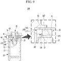
FIG. 9 illustrates a view for describing an action of a battery case assembly structure for an electric vehicle according to another embodiment of the present invention. - The present invention will be described more fully hereinafter with reference to the accompanying drawings, in which embodiments of the invention are shown. As those skilled in the art would realize, the described embodiments may be modified in various different ways, all without departing from the spirit or scope of the present invention.
- In order to clearly describe the present invention, parts that are irrelevant to the description are omitted, and identical or similar constituent elements throughout the specification are denoted by the same reference numerals.
- Since the size and thickness of each configuration shown in the drawings are arbitrarily shown for convenience of description, the present invention is not necessarily limited to configurations illustrated in the drawings, and in order to clearly illustrate several parts and areas, enlarged thicknesses are shown.
- In the following description, dividing names of components into first, second, and the like is to divide the names because the names of the components are the same, and an order thereof is not particularly limited.
- In the present specification, unless explicitly described to the contrary, the word "comprise" and variations such as "comprises" or "comprising" will be understood to imply the inclusion of stated elements but not the exclusion of any other elements.
-
FIG. 1 illustrates an exploded perspective view showing an assembly structure of a battery case for an electric vehicle according to an embodiment of the present invention. - Referring to
FIG. 1 , anassembly structure 100 of a battery case for an electric vehicle according to an embodiment of the present invention is mounted in an underbody of the electric vehicle, and may be applied to a battery pack that applies high voltage power to a driving motor. - Herein, the battery pack accommodates a plurality of battery modules therein, each of which is an aggregation of battery cells capable of charging and/or discharging, and includes a battery management system (BMS) that senses a voltage, a current, and a temperature of the battery modules and performs operation control.
- However, it should not be understood that a protection scope of the present invention is limitedly applied to a battery pack employed in an electric vehicle, and a technical idea of the present invention may be applied to any battery pack employed in various mobile devices and fully automatic devices.
- Hereinafter, in the drawing, a portion close to an upper side is defined as an upper portion, an upper end, an upper surface, and an upper end portion, and a portion close to a lower side is defined as a lower portion, a lower end, a lower surface, and a lower end portion.
- Furthermore, in the following, an end (one/first side or the other/second side) may be defined as either end, and may be defined as a certain portion (one/first side portion or the other/second side portion) including the end.
- The
assembly structure 100 of the battery case for an electric vehicle according to the embodiment of the present invention is an assembly structure of a battery case accommodating battery modules, and has a structure capable of improving watertight performance with a simple configuration. - To this end, the
assemble structure 100 of the battery case for an electric vehicle according to the embodiment of the present invention includes alower case 10, firstfastening members 20, agasket 30, acover 40,second fastening members 50, and astopper head portion 60. - In the embodiment of the present invention, the
lower case 10 is a battery case for accommodating battery modules, and is mounted in an underbody of a vehicle body. Thelower case 10 may be formed to include one panel or two or more panels connected to each other. - The
lower case 10 may include accessory elements such as brackets, rods, plates, blocks, and collars for supporting various components to be described below. However, since the accessory elements are for installing each of the components to be described below in thelower case 10, in the embodiment of the present invention, the accessory elements are collectively referred to as thelower case 10, except in exceptional cases. -
FIG. 2 illustrates a partially enlarged perspective view ofFIG. 1 , showing an assembly structure of a battery case for an electric vehicle according to an embodiment of the present invention, andFIG. 3 illustrates a schematic cross-sectional diagram showing a state before assembling of a battery case assembly structure for an electric vehicle according to an embodiment of the present invention. - Referring to
FIG. 1 to FIG. 3 , thelower case 10 according to an embodiment of the present invention includes abottom plate 11 and awall 13. Thebottom plate 11 includes support means for supporting the battery modules. Since the support means are well known to those skilled in the art, a further description will be omitted. Thewall 13 is provided at an edge portion of thebottom plate 11. - Accordingly, the
lower case 10 forms an accommodation space in which an upper end is opened and a lower end is closed by thebottom plate 11 and thewall 13. Further, thewall 13 may be formed to include an outer wall and an inner wall coupled to each other. Thewall 13 may form an inner space and an upper surface through coupling of the outer wall and the inner wall. - Herein, mounting
holes 15 in which thefirst fastening members 20 may be mounted are formed in thewall 13. The mounting holes 15 are formed to be spaced apart from each other at a predetermined interval along an edge direction on the upper surface of thewall 13. - In the embodiment of the present invention, the
first fastening members 20 are fixed along the edge direction to thewall 13 of thelower case 10, and are mounted in the mounting holes 15. - The
first fastening members 20 are provided in a nut type, for example. Thefirst fastening members 20 each include anut portion 21 fixed to the corresponding mountinghole 15 of thewall 13. Afastening hole 23 vertically extending therethrough may be formed in thenut portion 21, and acoupling groove 25 coupled to an edge of the mountinghole 15 may be formed at an outer circumference side. - In the embodiment of the present invention, the
gasket 30 is positioned on an upper surface of thewall 13 along the edge direction of thelower case 10. Thegasket 30 is provided to be elastically and compressively deformable by a pressing force acting in a vertical direction. - The
gasket 30 is formed withgasket holes 31 into which thefirst fastening members 20 are fitted in the vertical direction. Thegasket 30 is formed with a plurality offirst gasket protrusions 33 supporting the upper surface of thewall 13 on a lower surface thereof. - In addition, the
gasket 30 is formed with a plurality ofsecond gasket protrusions 35 supporting the lower surface of thecover 40. Further, in thegasket 30, athird gasket protrusion 37 is formed along an inner circumference direction of thegasket hole 31. - In the embodiment of the present invention, the
cover 40 covers an upper open end of thelower case 10, and aflange portion 41 for pressing the upper portion of thegasket 30 is formed at an edge portion thereof. - Herein, a lower surface of the
flange portion 41 supports thesecond gasket protrusions 35 of thegasket 30. In addition, coupling holes 43 connected to the coupling holes 23 of thefirst coupling members 20 are formed in theflange portion 41. - In the embodiment of the present invention, the
second fastening members 50 are coupled to the coupling holes 43 of thecover 40, and are fastened to thenut portions 21 of thefirst fastening members 20 through the fastening holes 23. Thesecond fastening members 50 each include abolt 51 fastened to thenut portion 21. - The
second fastening members 50 may be fastened to thenut portions 21 of thefirst fastening members 20 with thegasket 30 between theflange portion 41 of thecover 40 and the upper surface of thewall 13 of thelower case 10, to compressively deform thegasket 30. As thegasket 30 is compressively deformed between theflange portion 41 and thewall 13, thegasket 30 may seal between thelower case 10 and thecover 40. - In the embodiment of the present invention, when the
first fastening members 20 and thesecond fastening members 50 are fastened, thestopper head portion 60 is to limit a compressive deformation amount of thegasket 30 that is compressively deformed between theflange portion 41 and thewall 13, to guide the compressive deformation of thegasket 30, and to fix a mounted position of thegasket 30. - That is, the
stopper head portion 60 is to prevent thegasket 30 from being crushed due to overcompressive deformation of thegasket 30 and to prevent thegasket 30 from being separated from a predetermined position due to the compression deformation. - Further, the
stopper head portion 60 may support an inner circumferential surface of thegasket hole 31 and thethird gasket protrusion 37 protruding from the inner circumferential surface. Thestopper head portion 60 is integrally provided with thefirst fastening members 20, and is integrally connected with thenut portions 21 of thefirst fastening members 20. -
FIG. 4 illustrates a stopper head portion applied to an assembly structure of a battery case for an electric vehicle according to an embodiment of the present invention. - Referring to
FIG. 1 to FIG. 4 , thestopper head portion 60 according to an embodiment of the present invention includes ahead body 61 integrally connected to anut portion 21 and agasket stopper 71 provided in thehead body 61. - The
head body 61 may be positioned at an upper portion of thefirst fastening member 20, may have an outer circumferential surface, may be formed at a predetermined height, may support the upper surface of thewall 13 of thelower case 10, and may limit the compressive deformation amount ofgasket 30. - The
head body 61 has acover support surface 63 for supporting the lower surface of theflange portion 41 of thecover 40, and awall support surface 65 for supporting the upper surface of the edge of the mountinghole 15 of thewall 13. - The
gasket stopper 71 includes a stoppinggroove 73 formed on the outer circumferential surface of thehead body 61 along an outer circumferential direction. The stoppinggroove 73 is provided as a groove formed on the outer circumferential surface of thehead body 61 along the outer circumferential direction. The stoppinggroove 73 may support thethird gasket protrusion 37 in thegasket hole 31, and may set a displacement of thegasket 30 before and after compression. - Herein, the
head body 61 includes anupper rib 67 and alower rib 69 respectively provided on upper and lower sides with the stoppinggroove 73 interposed therebetween. - The
upper rib 67 supports thethird gasket protrusion 37 through the stoppinggroove 73, and supports an upper inner peripheral surface of thegasket hole 31 before thegasket 30 is compressively deformed. - In addition, the
lower rib 69 supports thethird gasket protrusion 37 through the stoppinggroove 73, and supports a lower inner peripheral surface of thegasket hole 31 after thegasket 30 is compressively deformed. - Hereinafter, an assembly process and an action of the battery
case assembly structure 100 for an electric vehicle according to an embodiment of the present invention will be described in detail with reference to the accompanying drawings. -
FIG. 5 illustrates a view for describing an action of a battery case assembly structure for an electric vehicle according to an embodiment of the present invention. - According to the embodiment of the present invention, the
first fastening members 20 are mounted in the mountinghole 15 of thewall 13 in thelower case 10, and thestopper head portion 60 is integrally formed in thefirst fastening members 20. In addition, thehead body 61 in thestopper head portion 60 is formed at a predetermined height to support the upper surface of the edge of the mountinghole 15 through thewall support surface 65. - In this state, in the embodiment of the present invention, the
gasket 30 is positioned on the upper surface of thewall 13, and in this case, thegasket 30 is positioned on the upper surface of thewall 13 while inserting thehead body 61 of thestopper head portion 60 into thegasket hole 31. - Herein, the
first gasket protrusions 33 of thegasket 30 support the upper surface of thewall 13, and thethird gasket protrusion 37 supports the stoppinggroove 73 of thehead body 61. - Further, in the
head body 61, theupper rib 67 supports thethird gasket protrusion 37 through the stoppinggroove 73, and supports the upper inner peripheral surface of thegasket hole 31. - Next, in the embodiment of the present invention, the
flange portion 41 of thecover 40 is positioned on thegasket 30, and thesecond gasket protrusion 35 of thegasket 30 supports the lower surface of theflange portion 41. In this case, in the embodiment of the present invention, thecoupling hole 43 of theflange portion 41 is aligned with thefastening hole 23 of thenut portion 21 through thehead body 61. - In this state, in the embodiment of the present invention, the
gasket 30 is positioned between the lower surface of theflange portion 41 and the upper surface of thewall 13, and as illustrated inFIG. 5 , thesecond fastening members 50 asbolts 51 are fastened to thenut portions 21 through thecoupling hole 43 of theflange portion 41 and thehead body 61. - Accordingly, the
gasket 30 is compressively deformed by fastening forces of the first andsecond fastening members flange portion 41 and thewall 13 to seal between thelower case 10 and thecover 40. - Specifically, in the embodiment of the present invention, a space between the upper surface of the
wall 13 and the lower portion of thegasket 30 is sealed through thefirst gasket protrusions 33, and a space between the lower surface of theflange portion 41 and the upper portion of thegasket 30 is sealed through thesecond gasket protrusion 35. - Herein, the lower surface of the
flange portion 41 supports thecover support surface 63 of thehead body 61. In addition, thelower rib 69 of thehead body 61 supports thethird gasket protrusion 37 through the stoppinggroove 73, and supports the lower inner peripheral surface of thegasket hole 31. That is, thethird gasket protrusion 37 supports thelower rib 69 while sliding in a downward direction by the stoppinggroove 73. - Accordingly, in the embodiment of the present invention, it is possible to prevent distortion due to overcompressive deformation of the
gasket 30, and to improve a sealing property of thegasket 30 by limiting a compressive deformation amount of thegasket 30 through thehead body 61 of thestopper head portion 60. - In addition, in the embodiment of the present invention, it is possible to prevent the
gasket 30 from being separated, and to ameliorate a leakage problem between thelower case 10 and thecover 40 as thethird gasket protrusion 37 of thegasket 30 is fixed to thehead body 61 while guiding the compressive deformation of thegasket 30 through the stoppinggroove 73 of thestopper head portion 60. - Further, in the embodiment of the present invention, it is possible to delete the bush and the guide protrusion as in the conventional art by the
stopper head portion 60 of thefirst fastening member 20. Accordingly, in the embodiment of the present invention, the structure of thegasket 30 and the assembly structure of thelower case 10 and thecover 40 through thegasket 30 may be simplified, and a manufacturing cost may be reduced. -
FIG. 6 illustrates an exploded perspective view showing an assembly structure of a battery case for an electric vehicle according to another embodiment of the present invention, andFIG. 7 illustrates a schematic cross-sectional diagram showing a state before assembling of a battery case assembly structure for an electric vehicle according to another embodiment of the present invention. In the drawings, the same reference numerals are assigned to the same components as in the previous embodiment. - Referring to
FIG. 6 andFIG. 7 , anassembly structure 200 of the battery case for an electric vehicle according to another embodiment of the present invention may constitute agasket stopper 171 having a stoppingstep 175 formed in ahead body 161, in astopper head portion 160 offirst fastening members 120. - In another embodiment of the present invention, configurations of the
lower case 10, thenut portion 21 of thefirst fastening members 120, thegasket 30 having the first, second, andthird gasket protrusions cover 40, and thesecond fastening members 50 are the same as in the previous embodiment, so detailed descriptions will be omitted. -
FIG. 8 illustrates a stopper head portion applied to an assembly structure of a battery case for an electric vehicle according to another embodiment of the present invention. - Referring to
FIG. 6 to FIG. 8 , in the embodiment of the present invention, thehead body 161 of thestopper head 160 has acover support surface 63 for supporting the lower surface of theflange portion 41 of thecover 40, and awall support surface 65 for supporting an upper surface of an edge of the mountinghole 15 of thewall 13 in thelower case 10. - In the embodiment of the present invention, a stopping
step 175 of thegasket stopper 171 is formed along an outer circumferential direction on the outer circumferential surface of thehead body 161. The stoppingstep 175 may form the outer peripheral surface of thehead body 161 stepwise in the vertical direction, may support thethird gasket protrusion 37 in thegasket hole 31 of thegasket 30, and may set a displacement of thegasket 30 before and after compression. - Further, the
head body 161 has a large-diameter surface 167 and a small-diameter surface 169 respectively positioned at an upper side and a lower side with the stoppingstep 175 therebetween. - The large-
diameter surface 167 supports thethird gasket protrusion 37 through the stoppingstep 175, and supports an upper inner peripheral surface of thegasket hole 31 before thegasket 30 is compressively deformed. - In addition, the small-
diameter surface 169 is a portion having a smaller outer diameter than that of the large-diameter surface 167, and supports thethird gasket protrusion 37 through the stoppingstep 175, and supports a lower inner peripheral surface of thegasket hole 31 after thegasket 30 is compressively deformed. - Hereinafter, an assembly process of the battery
case assembly structure 200 for an electric vehicle according to another embodiment of the present invention will be described in detail with reference to the accompanying drawings. - First, according to another embodiment of the present invention, as illustrated in
FIG. 9 , thesecond fastening members 50 are fastened to thenut portion 21 through thecoupling hole 43 of theflange portion 41 and thehead body 161 by placing thegasket 30 having thehead body 161 inserted into thegasket hole 31 between the upper surface of thewall 13 of thelower case 10 and the lower surface of theflange portion 41 of thecover 40. - Accordingly, the
gasket 30 is compressively deformed by fastening forces of the first andsecond fastening members flange portion 41 and thewall 13 to seal between thelower case 10 and thecover 40. - Herein, the lower surface of the
flange portion 41 supports thecover support surface 63 of thehead body 161. In addition, the small-diameter surface 169 of thehead body 161 supports thethird gasket protrusion 37 through the stoppingstep 175, and supports the lower inner peripheral surface of thegasket hole 31. That is, thethird gasket protrusion 37 supports the small-diameter surface 169 while sliding in a downward direction by the stoppinggroove 175. - Since remaining configurations and operational effects of the battery case assemble
structure 200 for an electric vehicle according to another embodiment of the present invention as described above are the same as in the previous embodiment, detailed descriptions thereof will be omitted. - While this invention has been described in connection with what is presently considered to be practical embodiments, it is to be understood that the invention is not limited to the disclosed embodiments, but, on the contrary, is intended to cover various modifications and equivalent arrangements included within the spirit and scope of the appended claims.
<Description of Symbols> 10: lowercase 11: bottom plate 13: wall 15: mounting hole 20, 120: first fastening member 21: nut portion 23: fastening hole 25: coupling groove 30: gasket 31: gasket hole 33: first gasket protrusion 35: second gasket protrusion 37: third gasket protrusion 40: cover 41: flange portion 43: coupling hole 50: second fastening member 51: bolt 60, 160: stopper head portion 61, 161: head body 63: cover support surface 65: wall support surface 67: upper rib 69: lower rib 71, 171: gasket stopper 73: stopping groove 167: large-diameter surface 169: small-diameter surface 175: stopping step 100, 200: battery case assemble structure
Claims (14)
- An assembly structure of a battery case for an electric vehicle, the structure comprising:a lower case configured to include a bottom plate and a wall provided at an edge of the bottom plate, to form an accommodating space with an upper end that is opened through the wall;a plurality of first fastening members fixed to the wall of the lower case along an edge direction;a gasket configured to have a gasket hole into which the first fastening members are fitted, to be elastically and compressively deformable through an upper surface of the wall;a cover configured to have a flange portion for pressing the gasket that is formed at an edge thereof;second fastening members coupled to a coupling hole formed in the flange portion of the cover and fastened to the first fastening members; anda stopper head portion integrally provided with the first fastening members, to limit a compressive deformation amount of the gasket and to fix a position of the gasket.
- The assembly structure of claim 1, wherein
the gasket includes:at least one first gasket protrusion configured to support the upper surface of the wall;at least one second gasket protrusion configured to support a lower surface of the flange portion of the cover; anda third gasket protrusion configured to support the stopper head portion on an inner circumferential surface of the gasket hole. - The assembly structure of claim 1, wherein
the wall forms an inner space and forms a mounting hole in which the first fastening members are mountable. - The assembly structure of claim 1, wherein
the first fastening member includes a nut portion that is fixed to a mounting hole formed in the wall. - The assembly structure of claim 4, wherein
the stopper head portion includes:a head body integrally formed with the nut portion to a predetermined height, to support the upper surface of the wall, and to limit the compressive deformation amount of the gasket; anda stopping groove formed on an outer circumferential surface of the head body along an outer circumferential direction to support a gasket protrusion provided on an inner circumferential surface of the gasket hole. - The assembly structure of claim 5, wherein
the heat body includes:a cover support surface configured to support a lower surface of the flange portion of the cover; anda wall support surface configured to support an upper surface of an edge of a mounting hole of the wall. - The assembly structure of claim 5, wherein
the head body includes an upper rib and a lower rib respectively provided at upper and lower sides thereof with the stopping groove therebetween. - The assembly structure of claim 4, wherein
the stopper head portion includes:a head body integrally formed with the nut portion to a predetermined height, to support the upper surface of the wall, and to limit the compressive deformation amount of the gasket; anda stopping groove formed on an outer circumferential surface of the head body along an outer circumferential direction to support the gasket protrusion provided on an inner circumferential surface of the gasket hole. - The assembly structure of claim 8, wherein
the heat body includes:a cover support surface configured to support a lower surface of the flange portion of the cover; anda wall support surface configured to support an upper surface of an edge of a mounting hole of the wall. - The assembly structure of claim 8, wherein
the head body includes a large-diameter surface formed at an upper side thereof, and a small-diameter surface formed at a lower side to have a smaller diameter than the large-diameter surface with the stopping step therebetween. - The assembly structure of claim 1, wherein
the second fastening member includes a bolt. - An assembly structure of a battery case for an electric vehicle, the structure comprising:a lower case configured to include a bottom plate and a wall provided at an edge of the bottom plate, to form an accommodating space with an upper end that is opened through the wall;a plurality of first fastening members configured to integrally form a head body supporting an upper surface of the wall to be fixed to the wall along an edge direction;a gasket configured to have a gasket hole into which the first fastening members are fitted, to be elastically and compressively deformable through an upper surface of the wall;a gasket stopper formed on an outer circumferential surface of the head body to support a gasket protrusion provided on an inner circumferential surface of the gasket hole;a cover configured to support an upper surface of the head body to form a flange portion at an edge portion thereof for pressing the gasket; andsecond fastening members coupled to a coupling hole provided in the flange portion of the cover and fastened to the first fastening members.
- The assembly structure of claim 12, wherein
the gasket stopper includes a stopping groove formed on an outer circumferential surface of the head body along an outer circumferential direction. - The assembly structure of claim 12, wherein
the gasket stopper includes a stopping step formed on an outer circumferential surface of the head body along an outer circumferential direction.
Applications Claiming Priority (1)
| Application Number | Priority Date | Filing Date | Title |
|---|---|---|---|
| KR1020200178069A KR102464315B1 (en) | 2020-12-18 | 2020-12-18 | Assembly structure of battery case for electric vehicle |
Publications (2)
| Publication Number | Publication Date |
|---|---|
| EP4016719A2 true EP4016719A2 (en) | 2022-06-22 |
| EP4016719A3 EP4016719A3 (en) | 2022-09-28 |
Family
ID=78528734
Family Applications (1)
| Application Number | Title | Priority Date | Filing Date |
|---|---|---|---|
| EP21206491.9A Withdrawn EP4016719A3 (en) | 2020-12-18 | 2021-11-04 | Assembly structure of battery case for electric vehicle |
Country Status (4)
| Country | Link |
|---|---|
| US (1) | US20220194197A1 (en) |
| EP (1) | EP4016719A3 (en) |
| KR (1) | KR102464315B1 (en) |
| CN (1) | CN114649625A (en) |
Families Citing this family (13)
| Publication number | Priority date | Publication date | Assignee | Title |
|---|---|---|---|---|
| KR102958868B1 (en) * | 2021-02-03 | 2026-04-29 | 현대모비스 주식회사 | Chassis frame for electric vehicle |
| KR20230115715A (en) * | 2022-01-27 | 2023-08-03 | 현대자동차주식회사 | Battery mounting structure for vehicle |
| KR20240008647A (en) * | 2022-07-12 | 2024-01-19 | 현대자동차주식회사 | Battery assembly mounting structure for vehicle |
| JP2024021615A (en) * | 2022-08-04 | 2024-02-16 | 株式会社Aescジャパン | battery pack |
| KR102819542B1 (en) * | 2022-10-04 | 2025-06-12 | 주식회사 동희산업 | Battery case |
| KR20240062612A (en) * | 2022-11-02 | 2024-05-09 | 주식회사 엘지에너지솔루션 | Battery pack |
| KR102516447B1 (en) | 2022-11-14 | 2023-04-03 | 군산대학교산학협력단 | Fire extinguisher for electric vehicle batteries |
| KR102855912B1 (en) * | 2023-10-05 | 2025-09-05 | 주식회사 동희산업 | Battery pack case mounting apparatus |
| KR102838624B1 (en) | 2023-10-05 | 2025-07-28 | (주)한엑스 | Battery case for electric vehicles type of air cooling |
| US12570135B2 (en) * | 2023-12-08 | 2026-03-10 | Rivian Ip Holdings, Llc | Joint for securing components of a vehicle |
| KR20250138589A (en) * | 2024-03-13 | 2025-09-22 | 주식회사 엘지에너지솔루션 | Battery case, battery pack and vehicle comprising the same |
| KR20260017779A (en) * | 2024-07-30 | 2026-02-06 | 주식회사 엘지에너지솔루션 | Gasket for supressing flame release in case of thermal propagation and battery pack having the same |
| JP2026043282A (en) * | 2024-08-28 | 2026-03-12 | 株式会社Aescジャパン | Battery pack |
Family Cites Families (12)
| Publication number | Priority date | Publication date | Assignee | Title |
|---|---|---|---|---|
| JP5760411B2 (en) * | 2010-12-08 | 2015-08-12 | Nok株式会社 | gasket |
| JP2014175143A (en) * | 2013-03-08 | 2014-09-22 | Nippon Pop Rivets & Fasteners Ltd | Sealing structure and sealing method for liquid intake port of sealed secondary battery |
| JP5786974B2 (en) * | 2014-01-15 | 2015-09-30 | 三菱自動車工業株式会社 | Battery case |
| KR101610487B1 (en) * | 2014-08-12 | 2016-04-07 | 현대자동차주식회사 | Case structure of high voltage battery for Electric Vehicle |
| KR101725908B1 (en) * | 2014-11-17 | 2017-04-11 | 주식회사 엘지화학 | Battery Pack Having Portion for Fixing of Gasket |
| KR102092118B1 (en) * | 2016-11-22 | 2020-03-23 | 주식회사 엘지화학 | Battery Pack Having Compression Limiter Portion of Gasket |
| KR20180064769A (en) * | 2016-12-06 | 2018-06-15 | 동아공업 주식회사 | Combination structure of installation battery pack of vehicle |
| CN207165693U (en) * | 2017-09-15 | 2018-03-30 | 江苏维科新能源科技有限公司 | A kind of sealing structure of lithium battery group |
| CN111740039A (en) * | 2019-03-25 | 2020-10-02 | 中天储能科技有限公司 | Battery box |
| MX2021012601A (en) * | 2019-04-19 | 2022-01-18 | Hexagon Purus North America Holdings Inc | ELECTRIC MOTORPROPULSION SYSTEM FOR HEAVY VEHICLES. |
| CN209641710U (en) * | 2019-04-19 | 2019-11-15 | 东风汽车有限公司 | battery pack shell |
| CN210723117U (en) * | 2019-12-11 | 2020-06-09 | 淮安骏盛新能源科技有限公司 | Sealing structure of new energy battery box |
-
2020
- 2020-12-18 KR KR1020200178069A patent/KR102464315B1/en active Active
-
2021
- 2021-09-15 US US17/475,401 patent/US20220194197A1/en not_active Abandoned
- 2021-11-04 EP EP21206491.9A patent/EP4016719A3/en not_active Withdrawn
- 2021-12-03 CN CN202111467437.2A patent/CN114649625A/en active Pending
Also Published As
| Publication number | Publication date |
|---|---|
| CN114649625A (en) | 2022-06-21 |
| KR20220087730A (en) | 2022-06-27 |
| US20220194197A1 (en) | 2022-06-23 |
| KR102464315B1 (en) | 2022-11-09 |
| KR102464315B9 (en) | 2023-04-12 |
| EP4016719A3 (en) | 2022-09-28 |
Similar Documents
| Publication | Publication Date | Title |
|---|---|---|
| US20220194197A1 (en) | Assembly structure of battery case for electric vehicle | |
| JP5965624B2 (en) | Inverter for automobile | |
| US7614469B2 (en) | Battery case and method for securing same | |
| US11394071B2 (en) | Battery assembly structure | |
| KR20200119587A (en) | Vehicle center floor structure | |
| WO2022110768A1 (en) | Battery pack and vehicle | |
| EP3346518B1 (en) | Housing for a battery module including a housing gasket | |
| KR102131613B1 (en) | battery case and manufacturing methods therof | |
| US20180130991A1 (en) | Rechargeable battery module and rechargeable battery pack | |
| US11787477B2 (en) | Chassis frame for electric vehicle | |
| WO2025112318A1 (en) | Underbody, vehicle body structure, and vehicle | |
| CN117261634B (en) | A car charging port structure and car thereof | |
| CN116266657A (en) | Vehicle battery pack components | |
| KR102440895B1 (en) | Hybrid type applied battery case | |
| US12227064B2 (en) | Battery housing for electric vehicles | |
| CN223471697U (en) | Battery pack box and battery pack | |
| KR20220147987A (en) | Vehicle battery mounting structure | |
| EP4456289A1 (en) | Battery pack | |
| KR20250051853A (en) | Battery case for hybrid vehicle | |
| CN118636645A (en) | Motor vehicle with high voltage battery | |
| US12283702B2 (en) | Seal for a battery housing of a high-voltage battery, method, battery housing, high-voltage battery and motor vehicle | |
| CN224036524U (en) | Shell of energy storage device and energy storage device | |
| US20250132447A1 (en) | Battery pack for vehicle | |
| KR20170125629A (en) | Energy storage module | |
| CN208216532U (en) | A kind of electric vehicle controller |
Legal Events
| Date | Code | Title | Description |
|---|---|---|---|
| PUAI | Public reference made under article 153(3) epc to a published international application that has entered the european phase |
Free format text: ORIGINAL CODE: 0009012 |
|
| STAA | Information on the status of an ep patent application or granted ep patent |
Free format text: STATUS: REQUEST FOR EXAMINATION WAS MADE |
|
| 17P | Request for examination filed |
Effective date: 20211123 |
|
| AK | Designated contracting states |
Kind code of ref document: A2 Designated state(s): AL AT BE BG CH CY CZ DE DK EE ES FI FR GB GR HR HU IE IS IT LI LT LU LV MC MK MT NL NO PL PT RO RS SE SI SK SM TR |
|
| PUAL | Search report despatched |
Free format text: ORIGINAL CODE: 0009013 |
|
| AK | Designated contracting states |
Kind code of ref document: A3 Designated state(s): AL AT BE BG CH CY CZ DE DK EE ES FI FR GB GR HR HU IE IS IT LI LT LU LV MC MK MT NL NO PL PT RO RS SE SI SK SM TR |
|
| RIC1 | Information provided on ipc code assigned before grant |
Ipc: H01M 50/262 20210101ALI20220822BHEP Ipc: H01M 50/249 20210101ALI20220822BHEP Ipc: H01M 50/244 20210101ALI20220822BHEP Ipc: H01M 50/24 20210101AFI20220822BHEP |
|
| STAA | Information on the status of an ep patent application or granted ep patent |
Free format text: STATUS: THE APPLICATION IS DEEMED TO BE WITHDRAWN |
|
| 18D | Application deemed to be withdrawn |
Effective date: 20230329 |