EP4016214A1 - Hybrid manufacturing system and method that reduces inaccessible support structures - Google Patents
Hybrid manufacturing system and method that reduces inaccessible support structures Download PDFInfo
- Publication number
- EP4016214A1 EP4016214A1 EP21213051.2A EP21213051A EP4016214A1 EP 4016214 A1 EP4016214 A1 EP 4016214A1 EP 21213051 A EP21213051 A EP 21213051A EP 4016214 A1 EP4016214 A1 EP 4016214A1
- Authority
- EP
- European Patent Office
- Prior art keywords
- tools
- build
- tool
- support structures
- orientation
- Prior art date
- Legal status (The legal status is an assumption and is not a legal conclusion. Google has not performed a legal analysis and makes no representation as to the accuracy of the status listed.)
- Withdrawn
Links
Images





Classifications
-
- G—PHYSICS
- G05—CONTROLLING; REGULATING
- G05B—CONTROL OR REGULATING SYSTEMS IN GENERAL; FUNCTIONAL ELEMENTS OF SUCH SYSTEMS; MONITORING OR TESTING ARRANGEMENTS FOR SUCH SYSTEMS OR ELEMENTS
- G05B19/00—Program-control systems
- G05B19/02—Program-control systems electric
- G05B19/18—Numerical control [NC], i.e. automatically operating machines, in particular machine tools, e.g. in a manufacturing environment, so as to execute positioning, movement or co-ordinated operations by means of program data in numerical form
- G05B19/4097—Numerical control [NC], i.e. automatically operating machines, in particular machine tools, e.g. in a manufacturing environment, so as to execute positioning, movement or co-ordinated operations by means of program data in numerical form characterised by using design data to control NC machines, e.g. CAD/CAM
- G05B19/4099—Surface or curve machining, making three-dimensional [3D] objects, e.g. desktop manufacturing
-
- B—PERFORMING OPERATIONS; TRANSPORTING
- B22—CASTING; POWDER METALLURGY
- B22F—WORKING METALLIC POWDER; MANUFACTURE OF ARTICLES FROM METALLIC POWDER; MAKING METALLIC POWDER; APPARATUS OR DEVICES SPECIALLY ADAPTED FOR METALLIC POWDER
- B22F10/00—Additive manufacturing of workpieces or articles from metallic powder
- B22F10/40—Structures for supporting workpieces or articles during manufacture and removed afterwards
-
- B—PERFORMING OPERATIONS; TRANSPORTING
- B22—CASTING; POWDER METALLURGY
- B22F—WORKING METALLIC POWDER; MANUFACTURE OF ARTICLES FROM METALLIC POWDER; MAKING METALLIC POWDER; APPARATUS OR DEVICES SPECIALLY ADAPTED FOR METALLIC POWDER
- B22F10/00—Additive manufacturing of workpieces or articles from metallic powder
- B22F10/20—Direct sintering or melting
- B22F10/28—Powder bed fusion, e.g. selective laser melting [SLM] or electron beam melting [EBM]
-
- B—PERFORMING OPERATIONS; TRANSPORTING
- B22—CASTING; POWDER METALLURGY
- B22F—WORKING METALLIC POWDER; MANUFACTURE OF ARTICLES FROM METALLIC POWDER; MAKING METALLIC POWDER; APPARATUS OR DEVICES SPECIALLY ADAPTED FOR METALLIC POWDER
- B22F10/00—Additive manufacturing of workpieces or articles from metallic powder
- B22F10/30—Process control
- B22F10/38—Process control to achieve specific product aspects, e.g. surface smoothness, density, porosity or hollow structures
- B22F10/385—Overhang structures
-
- B—PERFORMING OPERATIONS; TRANSPORTING
- B22—CASTING; POWDER METALLURGY
- B22F—WORKING METALLIC POWDER; MANUFACTURE OF ARTICLES FROM METALLIC POWDER; MAKING METALLIC POWDER; APPARATUS OR DEVICES SPECIALLY ADAPTED FOR METALLIC POWDER
- B22F10/00—Additive manufacturing of workpieces or articles from metallic powder
- B22F10/80—Data acquisition or data processing
- B22F10/85—Data acquisition or data processing for controlling or regulating additive manufacturing processes
-
- B—PERFORMING OPERATIONS; TRANSPORTING
- B22—CASTING; POWDER METALLURGY
- B22F—WORKING METALLIC POWDER; MANUFACTURE OF ARTICLES FROM METALLIC POWDER; MAKING METALLIC POWDER; APPARATUS OR DEVICES SPECIALLY ADAPTED FOR METALLIC POWDER
- B22F2203/00—Controlling
-
- B—PERFORMING OPERATIONS; TRANSPORTING
- B33—ADDITIVE MANUFACTURING TECHNOLOGY
- B33Y—ADDITIVE MANUFACTURING, i.e. MANUFACTURING OF THREE-DIMENSIONAL [3D] OBJECTS BY ADDITIVE DEPOSITION, ADDITIVE AGGLOMERATION OR ADDITIVE LAYERING, e.g. BY 3D PRINTING, STEREOLITHOGRAPHY OR SELECTIVE LASER SINTERING
- B33Y10/00—Processes of additive manufacturing
-
- B—PERFORMING OPERATIONS; TRANSPORTING
- B33—ADDITIVE MANUFACTURING TECHNOLOGY
- B33Y—ADDITIVE MANUFACTURING, i.e. MANUFACTURING OF THREE-DIMENSIONAL [3D] OBJECTS BY ADDITIVE DEPOSITION, ADDITIVE AGGLOMERATION OR ADDITIVE LAYERING, e.g. BY 3D PRINTING, STEREOLITHOGRAPHY OR SELECTIVE LASER SINTERING
- B33Y30/00—Apparatus for additive manufacturing; Details thereof or accessories therefor
-
- B—PERFORMING OPERATIONS; TRANSPORTING
- B33—ADDITIVE MANUFACTURING TECHNOLOGY
- B33Y—ADDITIVE MANUFACTURING, i.e. MANUFACTURING OF THREE-DIMENSIONAL [3D] OBJECTS BY ADDITIVE DEPOSITION, ADDITIVE AGGLOMERATION OR ADDITIVE LAYERING, e.g. BY 3D PRINTING, STEREOLITHOGRAPHY OR SELECTIVE LASER SINTERING
- B33Y50/00—Data acquisition or data processing for additive manufacturing
- B33Y50/02—Data acquisition or data processing for additive manufacturing for controlling or regulating additive manufacturing processes
-
- G—PHYSICS
- G05—CONTROLLING; REGULATING
- G05B—CONTROL OR REGULATING SYSTEMS IN GENERAL; FUNCTIONAL ELEMENTS OF SUCH SYSTEMS; MONITORING OR TESTING ARRANGEMENTS FOR SUCH SYSTEMS OR ELEMENTS
- G05B2219/00—Program-control systems
- G05B2219/30—Nc systems
- G05B2219/49—Nc machine tool, till multiple
- G05B2219/49016—Desktop manufacturing [DTM]; Solid freeform machining [SFM]; Solid freeform fabrication [SFF]
-
- Y—GENERAL TAGGING OF NEW TECHNOLOGICAL DEVELOPMENTS; GENERAL TAGGING OF CROSS-SECTIONAL TECHNOLOGIES SPANNING OVER SEVERAL SECTIONS OF THE IPC; TECHNICAL SUBJECTS COVERED BY FORMER USPC CROSS-REFERENCE ART COLLECTIONS [XRACs] AND DIGESTS
- Y02—TECHNOLOGIES OR APPLICATIONS FOR MITIGATION OR ADAPTATION AGAINST CLIMATE CHANGE
- Y02P—CLIMATE CHANGE MITIGATION TECHNOLOGIES IN THE PRODUCTION OR PROCESSING OF GOODS
- Y02P10/00—Technologies related to metal processing
- Y02P10/25—Process efficiency
Definitions
- Embodiments described herein include a hybrid manufacturing system that reduces inaccessible support structures.
- a model of a part is defined, the part targeted for a manufacturing operation that includes an additive process followed by a subtractive process.
- a plurality of potential build orientations of the additive process are defined, as are one or more removal tools of the subtractive process.
- support structures that are used by the additive process at the orientation is determined.
- One of the plurality of potential build orientations with minimal cost of inaccessible portions of the support structures by the set of subtractive tools is selected.
- the selected build orientation is used to build the part using the additive process and at least one tool in the set of tools for the subtractive process.
- a manufacturing operation in another embodiment, includes an additive process followed by a subtractive process.
- the subtractive process uses a removal tool.
- a model of a part targeted for the manufacturing operation is determined.
- the manufacturing process is modeled for a plurality of potential build orientations of the additive process. For each orientation of the plurality of potential build orientations, supports are determined that are used by the additive process at the orientation. One of the plurality of potential build orientations is selected that reduces a cost of inaccessible portions of the support structures. The selected build orientation is used to build the part using the additive process.
- Hybrid manufacturing relates to a process of manufacturing that combines two different process types usually performed on distinctly different machines, such as additive manufacturing (AM), subtractive manufacturing (SM), welding, deformation/bending, etc.
- Additive manufacturing includes such processes as fused deposition modeling, stereo-lithography, selective laser sintering, etc., and is colloquially referred to as 3-D printing.
- Additive manufacturing is capable of forming complex structures with customized material gradation, such as complex and efficient infill structures.
- Subtractive manufacturing is useful for producing high-precision mechanical parts.
- AM affords wide freedom in customizing the internal structures of parts
- SM can achieve finer precision and surface quality specifications than currently possible with AM, such as needed for functional interfaces requiring high-tolerance fit and assembly.
- Fabricating a part through SM involves progressively removing or machining material from raw stock until the part has been reduced to the desired form within a specified tolerance.
- Raw material is often removed by turning, drilling, or milling.
- Fabricating a part through AM involves progressively adding or depositing material onto a part being fabricated, often by adding successive layers, until the part approximates an intended shape and size, such as used with three-dimensional printing through fused deposition modeling (FDM).
- FDM fused deposition modeling
- metal AM is sometimes used in lieu of traditional metalworking, such as casting, but with more freedom in generating complex forms, to produce a near-net shape that is close enough to the final part.
- Functional interfaces may still be finished using SM to satisfy tolerancing and surface quality specifications.
- layer-by-layer AM processes such as FDM, support materials are printed into the lower layers of the near-net shape, allowing the upper layers to extend beyond the lower layers' width without sagging due to gravity. This may require SM post-processing to remove the support materials.
- Embodiments described herein include a method and system for automated optimization of the build orientation in additive manufacturing based on support structure accessibility. This is a systematic approach to automated build orientation optimization while ensuring removability of sacrificial support structures through subtractive processes (e.g., milling) in terms of 'accessibility' of every point of support given a 'set' of cutting tool assemblies, fixturing orientations, and substrate without imposing any artificial constraints on geometric complexity of part, support geometry, machining tools, and fixturing devices.
- the approach enables efficient and effective design space exploration by finding optimal build orientation for which its 'near-net' shape (part + supports) can be fabricated using additive manufacturing and post-processed using well-established subtractive machines.
- AM technologies are capable of fabricating geometrically complex parts by adding material layer-by-layer.
- the growing interest in AM, specifically metal-AM stems from its ability to leverage geometric complexity to design high-performance lightweight designs for applications in aerospace, automotive, medical, etc.
- metal-AM technologies such as powder-bed fusion
- sacrificial support structures are needed in 'overhanging' regions to dissipate excessive heat and ensure successful build of the near-net shape (part + support).
- the overhanging regions are often specified in terms of an overhang angle, which is a measure of the maximum amount that one layer can extend beyond the layer on which it is deposited without requiring a support.
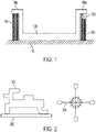
- FIG. 1 A simplified diagram of an AM part with support structures is shown in the diagram of FIG. 1 .
- An AM manufactured part 100 is built on a fixture 102.
- supports 104 are built together with the part 100.
- a removal tool 106 is used to remove the supports 104.
- the removal tool 106 may include any combination of tools that cut, grind, sand, burnish, slice, carve, etc., and any reference herein to "cutting" or “cutting tools” herein may apply equally to any of these removal tool types.
- tool and “tool assembly” may be used interchangeably herein, as a tool may include non cutting components (e.g., chucks, bearings, etc.) that could limit regions that the tool can be used.
- removal tool 106 may be oriented differently than shown here in order to leave the lower portion of the flanges 100a smooth.
- Subtractive manufacturing techniques such as multi-axis machining have been widely used for manufacturing high-quality re-producible parts across multiple industries including aerospace and automotive.
- SM multi-axis machining
- one begins with a raw stock of material and gradually carve out material until the desired shape emerges.
- an AM process is first used to obtain a near-net shape, and temporary supports may have been added to obtain this shape.
- the SM process is used at least to remove the supports, and may also be used to bring certain regions of the near-net shape to a final dimensional tolerance, e.g., precision machining of mounting interfaces.
- An accessibility analysis can be used for imposing support accessibility constraint through multi-axis machining; for more details see Amir M. Mirzendehdel, Morad Behandish, and Saigopal Nelaturi - "Topology optimization with accessibility constraint for multi-axis machining," ComputerAided Design, 122 (May, 2020), 102825.
- T a tool assembly
- T (H U K)
- H and K are the holder and the cutter, respectively.
- the IMF is a continuous spatial field that quantifies to what extent different points in a design domain cannot be accessed by the set of one or more tools for the subtractive process. Equation (1) can be further extended to consider multiple removal tools. This may include separate removal machines, as well as a single machine with multiple exchangeable parts, e.g., different size/shape cutting heads.
- f IMF x O min 1 ⁇ i ⁇ n T f I x O T i K i
- the inaccessibility measure field for a plurality of subtractive tool assemblies at every query point of the design domain can be calculated as a minimum of an inaccessibility measure for different configurations at which a query point can be removed by a subtractive tool of the subtractive tool assemblies as defined in Equation (3).
- the configurations over which the minimum is calculated includes at least one of the displacements that bring the sharp points on the subtractive tool in contact with the query point, and the tool orientations that are available to the tool assembly.
- the inaccessibility measure is defined by a volume of collision between the subtractive tool and an intermediate part design.
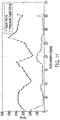
- FIG. 2 a diagram illustrates a simplified part 200 used in accessibility analysis according to an example embodiment.
- the part is shown on a build substrate 202 and a removal (e.g., cutting tool) 204 is shown in four different example orientations, 0°, 90°, 180°, and 270°, although may be rotated in any orientation angle in this range.
- the IMF for the near net shape of part 300 is shown in FIG. 4 .
- FIGS. 4 and 5 The accessibility analysis for near-net AM part 300 is shown in FIGS. 4 and 5 .
- FIG. 4 is an IMF over the near-net shape and
- FIG. 5 is the IMF over the supports.
- the diagrams in FIGS. 6-9 show accessible supports (single hatching) and inaccessible supports (cross-hatching) at orientations 0°, 30°, 135°, 200°, all for 45° overhang angle. For the 135° build orientation ( FIG. 8 ), there are no inaccessible supports.
- the process parameters some process parameters besides selected tools e.g., maximum overhang angle, fixture, deposition speed, etc.
- process parameters may be fixed for each build orientation or be varied together with build orientation and/or tooling.
- the overhang angle may be a parameter that is relaxed or optimized together with support accessibility.
- Another process parameter that can be varied is the selection of different available fixtures that secure the part as it is being manufactured. For example, a larger fixture may be preferred for reasons such as stability, but a smaller fixture may allow more regions of the part and supports to be accessed by an SM tool, although may be less stable and potentially reduce the quality of the finished part.
- the IMF can be used to set accessibility constraints on support structures.
- a framework, method, and system can enable automatic build orientation optimization such that the resulting shape is guaranteed to be manufacturable using AM and post-processed using SM processes.
- the proposed automated design process is as shown in FIG. 10 .
- the process involves sampling a number of build angles, in particular build orientations ⁇ build ⁇ SO3, as indicated by loop limit 1000.
- support structures are generated 1001, e.g., mathematically modeled using a format compatible with the part geometry. This may involve re-positioning the substrate/fixture relative to the part and generating support structures based on maximum overhang angle and support type (e.g., beams, tree-like, etc.).
- an accessibility analysis 1002 is performed. This analysis 1002 may involve constructing the configuration space (C-space) of part, substrate and tool assembly, sampling tool rotations in C-space, and constructing the inaccessibility measure field.
- the objective values are calculated 1003. This calculation 1003 may involve, for example, computing volumes of accessible supports and other objective cost functions such as overall support volume, build time, etc.
- block 1000 exits via path 1004, and the optimal build angle is determined 1005, e.g., based on minimizing cost of inaccessible supports, support accessibility and other objectives. In some cases, optimal build angle may not have the minimum cost of inaccessible supports but a reduced cost compared to a non-optimized version. For example, a zero inaccessible support orientation may be possible, but it may have other disadvantages (e.g., total support volume, build quality) such that an orientation is chosen with a still reduced but non-zero inaccessible portions.
- the multi-axis machining tool 204 is also shown in FIG. 2 .
- the graph in FIG. 11 shows the volume of support and inaccessible supports at different build orientations at a conservative 90° overhang angle.
- the cost is assumed to be equivalent to the volume of inaccessible supports, although this example could be adapted to account for other cost measures, e.g., removal tool cost, removal time, etc.
- the graph in FIG. 13 shows the volume of support and inaccessible supports at different build orientations at a 45° overhang angle.
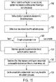
- FIG. 15 a flowchart shows a method according to an example embodiment.
- the method involves defining 1500 a model of a part targeted for a manufacturing operation that comprises an additive process followed by a subtractive process.
- the model may define the part's geometry, tolerances, materials, etc.
- a plurality of potential build orientations of the additive process are defined 1501.
- One or more tools of the subtractive process are also defined 1502.
- Block 1503 represents an iteration through each orientation of the plurality of potential build orientations, in which support structures are determined 1504 that that is used by the additive process at the orientation.
- the selected build orientation has a minimal a cost of portions of the support structures that are inaccessible via the one or more removal tools.
- minimum in this context is not necessarily an absolute or global minimum, as it could be a local minimum, Pareto-optimal, etc.
- the local or global minimum cost may be at an orientation that is not analyzed, and presumably the selected orientation would be have a minimal cost that is near the local or global minimum.
- the selected build orientation may also be chosen by jointly minimizing other factors in together with the cost of the inaccessible support portions, such as a cost of a selected removal tool, and/or a total volume of the support structures.
- the selected build orientation is used 1506 to build the part using the additive and subtractive processes.
- FIG. 16 a block diagram shows a system and computing apparatus 1600 that may be used to implement methods according to an example embodiment.
- the apparatus 1600 includes one or more processors 1602 such as a central processing unit, co-processor, digital signal processor, etc.
- the processor 1602 is coupled to memory, which may include both random access memory 1604 and persistent storage 1606, via one or more input/output busses 1608.
- Other general-purpose or special-purpose hardware may be coupled to the bus 1608, such as graphics processing unit (GPU) 1611 and network interface 1612.
- GPU graphics processing unit
- the functions of the apparatus 1600 described below may be implemented via multiple devices, e.g., via client-server arrangement, clustered computing, cloud computing, etc.
- the network interface 1612 facilitates communications via a network 1614, using wired or wireless media, with two or more manufacturing apparatuses 1616 that can perform AM and SM manufacturing operations.
- the manufacturing apparatuses 1616 include 3D printers, selective laser metal sintering machines, computer numeric controlled (CNC) mills, CNC lathes, CNC laser cutters, CNC water cutters, etc.
- Data may also be transferred to the manufacturing apparatuses 1616 using non-network data transfer interfaces, e.g., via portable data storage drives, point-to-point communication, etc.
- the apparatus 1600 includes software 1620 such as an operating system 1622 and drivers 1624 that facilitate communications between user-level programs and the hardware.
- the software 1620 includes a process planner 1626 that facilitates optimizing an AM build orientation of the part to minimize inaccessible supports that are later removed by an SM process.
- the inaccessibility of supports may be a sole optimization objective, or may be optimized jointly with other objectives, such as support volume and SM cost.
- the process planner 1626 interfaces with a geometry database 1634 that includes the part geometry and other factors (e.g., build tolerances, materials, etc.)
- the process planner 1626 also interfaces with a manufacturing database 1634 that provides information such as tool geometry and costs, fixture geometry, and AM parameters (e.g., allowable overhang angles).
- the resulting build orientation and SM removal operations can be stored as a process plan, e.g., in a plans database 1630.
- the plans can be communicated to one or more of the manufacturing apparatuses 1616 to produce parts according to the plans.
- the systems and methods described above can automatically optimize the build orientation based on accessibility of support structures.
- This can be implemented in process planner that can automatically find the best AM process and support generation strategy based on support accessibility.
- process planner can automatically find the Pareto-optimal build orientation based on accessibility of support structures and other competing objectives.
Landscapes
- Engineering & Computer Science (AREA)
- Manufacturing & Machinery (AREA)
- Chemical & Material Sciences (AREA)
- Materials Engineering (AREA)
- Automation & Control Theory (AREA)
- Physics & Mathematics (AREA)
- Plasma & Fusion (AREA)
- Human Computer Interaction (AREA)
- General Physics & Mathematics (AREA)
- Powder Metallurgy (AREA)
Abstract
Description
- This invention was made with government support under contract number G011.3809.00 awarded by Defense Advanced Research Projects Agency (DARPA). The government has certain rights in the invention.
- Embodiments described herein include a hybrid manufacturing system that reduces inaccessible support structures. In one embodiment, a model of a part is defined, the part targeted for a manufacturing operation that includes an additive process followed by a subtractive process. A plurality of potential build orientations of the additive process are defined, as are one or more removal tools of the subtractive process. For each orientation of the plurality of potential build orientations, support structures that are used by the additive process at the orientation is determined. One of the plurality of potential build orientations with minimal cost of inaccessible portions of the support structures by the set of subtractive tools is selected. The selected build orientation is used to build the part using the additive process and at least one tool in the set of tools for the subtractive process.
- In another embodiment, a manufacturing operation is defined that includes an additive process followed by a subtractive process. The subtractive process uses a removal tool. A model of a part targeted for the manufacturing operation is determined. The manufacturing process is modeled for a plurality of potential build orientations of the additive process. For each orientation of the plurality of potential build orientations, supports are determined that are used by the additive process at the orientation. One of the plurality of potential build orientations is selected that reduces a cost of inaccessible portions of the support structures. The selected build orientation is used to build the part using the additive process.
- These and other features and aspects of various embodiments may be understood in view of the following detailed discussion and accompanying drawings.
- The discussion below makes reference to the following figures, wherein the same reference number may be used to identify the similar/same component in multiple figures. The drawings are not necessarily to scale.
-
FIG. 1 is a diagram showing aspects of hybrid manufacturing according to an example embodiment; -
FIG. 2 is a diagram illustrating a simplified part and removal tool used in accessibility analysis according to an example embodiment; -
FIG. 3 is a diagram showing the near net shape of part shown inFIG. 2 with supports according to an example embodiment; -
FIGS. 4 and5 are diagrams showing results of inaccessibility analysis of the shape shown inFIG. 3 according to an example embodiment; -
FIGS. 6-9 are diagrams showing accessible and inaccessible supports at different build orientations of the part shown inFIG. 2 according to an example embodiment; -
FIG. 10 is a flowchart showing an automated design process according to an example embodiment; -
FIG. 11 is a graph showing volume of support and inaccessible supports at different build orientations for a 90° overhang angle according to an example embodiment; -
FIG. 12 is a diagram showing accessible and inaccessible supports at a minimal-inaccessible-support orientation of the part shown inFIG. 2 for a 90° overhang angle according to an example embodiment; -
FIG. 13 is a graph showing volume of support and inaccessible supports at different build orientations for a 45° overhang angle according to an example embodiment; -
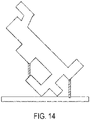
FIG. 14 is a diagram showing accessible and inaccessible supports at a minimal-inaccessible-support orientation of the part shown inFIG. 2 for a 45° overhang angle according to an example embodiment; -
FIG. 15 is a flowchart showing a method according to an example embodiment; and -
FIG. 16 is a block diagram of a system and apparatus according to an example embodiment. - The present disclosure relates to hybrid manufacturing process planning. Hybrid manufacturing relates to a process of manufacturing that combines two different process types usually performed on distinctly different machines, such as additive manufacturing (AM), subtractive manufacturing (SM), welding, deformation/bending, etc. Additive manufacturing includes such processes as fused deposition modeling, stereo-lithography, selective laser sintering, etc., and is colloquially referred to as 3-D printing. Additive manufacturing is capable of forming complex structures with customized material gradation, such as complex and efficient infill structures. Subtractive manufacturing is useful for producing high-precision mechanical parts. Although AM affords wide freedom in customizing the internal structures of parts, SM can achieve finer precision and surface quality specifications than currently possible with AM, such as needed for functional interfaces requiring high-tolerance fit and assembly.
- Historically, the manufacturing of parts from raw stock or material has involved these two distinct, albeit combinable, manufacturing processes. Fabricating a part through SM involves progressively removing or machining material from raw stock until the part has been reduced to the desired form within a specified tolerance. Raw material is often removed by turning, drilling, or milling. Fabricating a part through AM involves progressively adding or depositing material onto a part being fabricated, often by adding successive layers, until the part approximates an intended shape and size, such as used with three-dimensional printing through fused deposition modeling (FDM).
- For instance, metal AM is sometimes used in lieu of traditional metalworking, such as casting, but with more freedom in generating complex forms, to produce a near-net shape that is close enough to the final part. Functional interfaces may still be finished using SM to satisfy tolerancing and surface quality specifications. In many cases, in layer-by-layer AM processes such as FDM, support materials are printed into the lower layers of the near-net shape, allowing the upper layers to extend beyond the lower layers' width without sagging due to gravity. This may require SM post-processing to remove the support materials.
- Embodiments described herein include a method and system for automated optimization of the build orientation in additive manufacturing based on support structure accessibility. This is a systematic approach to automated build orientation optimization while ensuring removability of sacrificial support structures through subtractive processes (e.g., milling) in terms of 'accessibility' of every point of support given a 'set' of cutting tool assemblies, fixturing orientations, and substrate without imposing any artificial constraints on geometric complexity of part, support geometry, machining tools, and fixturing devices. The approach enables efficient and effective design space exploration by finding optimal build orientation for which its 'near-net' shape (part + supports) can be fabricated using additive manufacturing and post-processed using well-established subtractive machines.
- As noted above, AM technologies are capable of fabricating geometrically complex parts by adding material layer-by-layer. The growing interest in AM, specifically metal-AM, stems from its ability to leverage geometric complexity to design high-performance lightweight designs for applications in aerospace, automotive, medical, etc. However, in most of metal-AM technologies such as powder-bed fusion, sacrificial support structures are needed in 'overhanging' regions to dissipate excessive heat and ensure successful build of the near-net shape (part + support). The overhanging regions are often specified in terms of an overhang angle, which is a measure of the maximum amount that one layer can extend beyond the layer on which it is deposited without requiring a support. For example, if deposition process extrudes a material that is about 1 mm in diameter, and overhang angle of 45° would allow a layer to extend about 1mm beyond the layer below without requiring a support structure underneath. Since the support structure is typically removed using an SM process such as milling, the supports need be 'accessible' by the available machining tools and fixtures.
- A simplified diagram of an AM part with support structures is shown in the diagram of
FIG. 1 . An AM manufacturedpart 100 is built on afixture 102. To ensure thetop flanges 100a are built to the proper shape,supports 104 are built together with thepart 100. After the AM process is complete, aremoval tool 106 is used to remove thesupports 104. Theremoval tool 106 may include any combination of tools that cut, grind, sand, burnish, slice, carve, etc., and any reference herein to "cutting" or "cutting tools" herein may apply equally to any of these removal tool types. Also note that the terms "tool" and "tool assembly" may be used interchangeably herein, as a tool may include non cutting components (e.g., chucks, bearings, etc.) that could limit regions that the tool can be used. Note that theremoval tool 106 may be oriented differently than shown here in order to leave the lower portion of theflanges 100a smooth. - There are numerous published works on build orientation optimization considering overall support volume, build time, surface quality, volumetric error, and mechanical strength. However, to the best of our knowledge, there is no systematic approach to optimizing build orientation based on support accessibility for general set of tool assemblies, fixtures, and support types.
- Subtractive manufacturing techniques such as multi-axis machining have been widely used for manufacturing high-quality re-producible parts across multiple industries including aerospace and automotive. In SM, one begins with a raw stock of material and gradually carve out material until the desired shape emerges. In a hybrid model, an AM process is first used to obtain a near-net shape, and temporary supports may have been added to obtain this shape. The SM process is used at least to remove the supports, and may also be used to bring certain regions of the near-net shape to a final dimensional tolerance, e.g., precision machining of mounting interfaces.
- An accessibility analysis can be used for imposing support accessibility constraint through multi-axis machining; for more details see Amir M. Mirzendehdel, Morad Behandish, and Saigopal Nelaturi - "Topology optimization with accessibility constraint for multi-axis machining," ComputerAided Design, 122 (May, 2020), 102825. Let us assume that a tool assembly, T, can operate with all six degrees of freedom (three translations and three rotations) available for a rigid body, where T = (H U K), and where H and K are the holder and the cutter, respectively. Let us also denote the part as Ω, the substrate (and other fixtures) as F, and support structures as S.
- Mathematically the configuration space of rigid motions is represented as


where point


- The same effect can be obtained by querying the convolution at t := (x - R k) so that the rigid transformation (R, t) brings the sharp point in contact with the query point: (R, t)k = R k + t = R k + (x - R k) = x, as expected. The IMF is thus computed as follows:

- Generally, the IMF is a continuous spatial field that quantifies to what extent different points in a design domain cannot be accessed by the set of one or more tools for the subtractive process. Equation (1) can be further extended to consider multiple removal tools. This may include separate removal machines, as well as a single machine with multiple exchangeable parts, e.g., different size/shape cutting heads. Given nT ≥ 1 available tool assemblies Ti = (Hi U Ki) for 1 ≤ i ≤ nT , we compute their combined IMF as in Equation (3) below by applying another minimum operation over different tools to identify the tool(s) with the smallest volumetric interference at available orientations and sharp points, in which ƒ IMF(x; O,Ti, Ki ) are computed from Equation (2).

- The inaccessibility measure field for a plurality of subtractive tool assemblies at every query point of the design domain (ƒ IMF(x; O) can be calculated as a minimum of an inaccessibility measure for different configurations at which a query point can be removed by a subtractive tool of the subtractive tool assemblies as defined in Equation (3). The configurations over which the minimum is calculated includes at least one of the displacements that bring the sharp points on the subtractive tool in contact with the query point, and the tool orientations that are available to the tool assembly. The inaccessibility measure is defined by a volume of collision between the subtractive tool and an intermediate part design.
- There may be challenges in optimizing the build orientation based support accessibility. For example, minimizing volume of support structures is not necessarily the same of minimizing the volume or cost of inaccessible supports, e.g., the volume of inaccessible supports can decrease at a higher overall support volume. Also, calculating large number of build orientations can become time and computationally intensive, thus the analysis needs to be efficient and parallelizable. Another issue to consider when optimizing build orientations is that there are numerous types of support geometries (e.g., beams or tree-like structures) and overhang angles (e.g., between 45° to 90°, inclusive) depending on the AM process. An overhang angle of 90° would allow no extension beyond the lower layer. Also, the cutter's shape in the SM process cannot be ignored. Hence, there is no clear way to assign a correspondence between the translations

- When optimizing the build orientation, the tool, substrate, and fixture shapes cannot be ignored in a general setting. Also, the analysis is highly non-linear, meaning a small change in

FIG. 2 , a diagram illustrates asimplified part 200 used in accessibility analysis according to an example embodiment. The part is shown on abuild substrate 202 and a removal (e.g., cutting tool) 204 is shown in four different example orientations, 0°, 90°, 180°, and 270°, although may be rotated in any orientation angle in this range. InFIG. 3 , a diagram shows the near-net AM part 300 at θ build = 0° withsupports 300a. The IMF for the near net shape ofpart 300 is shown inFIG. 4 . - The accessibility analysis for near-
net AM part 300 is shown inFIGS. 4 and5 .FIG. 4 is an IMF over the near-net shape andFIG. 5 is the IMF over the supports. The diagrams inFIGS. 6-9 show accessible supports (single hatching) and inaccessible supports (cross-hatching) atorientations 0°, 30°, 135°, 200°, all for 45° overhang angle. For the 135° build orientation (FIG. 8 ), there are no inaccessible supports. Note that the process parameters some process parameters besides selected tools (e.g., maximum overhang angle, fixture, deposition speed, etc.) can influence the geometry of the supports and their accessibility. - These process parameters may be fixed for each build orientation or be varied together with build orientation and/or tooling. For example, it may be possible to build using a range of overhang angles, with more overhang possibly affecting some quality of the part such as surface smoothness that may or may not be acceptable in some cases. In such a scenario, the overhang angle may be a parameter that is relaxed or optimized together with support accessibility. Another process parameter that can be varied is the selection of different available fixtures that secure the part as it is being manufactured. For example, a larger fixture may be preferred for reasons such as stability, but a smaller fixture may allow more regions of the part and supports to be accessed by an SM tool, although may be less stable and potentially reduce the quality of the finished part.
- The IMF can be used to set accessibility constraints on support structures. A framework, method, and system can enable automatic build orientation optimization such that the resulting shape is guaranteed to be manufacturable using AM and post-processed using SM processes. At a high level, the proposed automated design process is as shown in
FIG. 10 . The process involves sampling a number of build angles, in particular build orientations Θbuild ⊆ SO3, as indicated byloop limit 1000. For each angle analyzed, support structures are generated 1001, e.g., mathematically modeled using a format compatible with the part geometry. This may involve re-positioning the substrate/fixture relative to the part and generating support structures based on maximum overhang angle and support type (e.g., beams, tree-like, etc.). - After the support structures are generated, an
accessibility analysis 1002 is performed. Thisanalysis 1002 may involve constructing the configuration space (C-space) of part, substrate and tool assembly, sampling tool rotations in C-space, and constructing the inaccessibility measure field. After theaccessibility analysis 1002, the objective values are calculated 1003. Thiscalculation 1003 may involve, for example, computing volumes of accessible supports and other objective cost functions such as overall support volume, build time, etc. After all angles have been analyzed, block 1000 exits viapath 1004, and the optimal build angle is determined 1005, e.g., based on minimizing cost of inaccessible supports, support accessibility and other objectives. In some cases, optimal build angle may not have the minimum cost of inaccessible supports but a reduced cost compared to a non-optimized version. For example, a zero inaccessible support orientation may be possible, but it may have other disadvantages (e.g., total support volume, build quality) such that an orientation is chosen with a still reduced but non-zero inaccessible portions. - These five activities involve understanding of geometric, topological, material, and physical aspects of the available manufacturing capabilities and should not be performed in isolation. Consider the
part 200 shown inFIG. 2 , where overhang angle α = 45° and the set of build orientations Θbuild ⊆ SO3 is:
- The
multi-axis machining tool 204 is also shown inFIG. 2 . The set of tool directions is:
- The graph in
FIG. 11 shows the volume of support and inaccessible supports at different build orientations at a conservative 90° overhang angle. For this example, the cost is assumed to be equivalent to the volume of inaccessible supports, although this example could be adapted to account for other cost measures, e.g., removal tool cost, removal time, etc. There are no orientations with zero inaccessible support volumes. The orientation with minimum inaccessible support volume is θbuild = 305°. The supports for θbuild = 305° are shown in the diagram ofFIG. 12 . The graph inFIG. 13 shows the volume of support and inaccessible supports at different build orientations at a 45° overhang angle. There are no inaccessible support volumes at build angles 45°, 135°, 225°, 295°, 305°, 310°, 315°. However, the set of orientations with accessible supports can be further optimized based on other competing objectives such as overall cost/volume of all supports. In this case the Pareto-optimal solution is θbuild = 135°. The supports at θbuild = 135° are shown in the diagram ofFIG. 14 . - In
FIG. 15 , a flowchart shows a method according to an example embodiment. The method involves defining 1500 a model of a part targeted for a manufacturing operation that comprises an additive process followed by a subtractive process. The model may define the part's geometry, tolerances, materials, etc. A plurality of potential build orientations of the additive process are defined 1501. One or more tools of the subtractive process are also defined 1502.Block 1503 represents an iteration through each orientation of the plurality of potential build orientations, in which support structures are determined 1504 that that is used by the additive process at the orientation. - One of the plurality of potential build orientations is selected 1505. The selected build orientation has a minimal a cost of portions of the support structures that are inaccessible via the one or more removal tools. Note that the term "minimal" in this context is not necessarily an absolute or global minimum, as it could be a local minimum, Pareto-optimal, etc. Also, depending on the granularity of the build orientations analyzed, the local or global minimum cost may be at an orientation that is not analyzed, and presumably the selected orientation would be have a minimal cost that is near the local or global minimum. The selected build orientation may also be chosen by jointly minimizing other factors in together with the cost of the inaccessible support portions, such as a cost of a selected removal tool, and/or a total volume of the support structures. The selected build orientation is used 1506 to build the part using the additive and subtractive processes.
- The methods and processes described above can be implemented on computer hardware, e.g., workstations, servers, as known in the art. In
FIG. 16 , a block diagram shows a system andcomputing apparatus 1600 that may be used to implement methods according to an example embodiment. Theapparatus 1600 includes one ormore processors 1602 such as a central processing unit, co-processor, digital signal processor, etc. Theprocessor 1602 is coupled to memory, which may include bothrandom access memory 1604 andpersistent storage 1606, via one or more input/output busses 1608. Other general-purpose or special-purpose hardware may be coupled to thebus 1608, such as graphics processing unit (GPU) 1611 andnetwork interface 1612. Note that the functions of theapparatus 1600 described below may be implemented via multiple devices, e.g., via client-server arrangement, clustered computing, cloud computing, etc. - The
network interface 1612 facilitates communications via anetwork 1614, using wired or wireless media, with two ormore manufacturing apparatuses 1616 that can perform AM and SM manufacturing operations. Examples of themanufacturing apparatuses 1616 include 3D printers, selective laser metal sintering machines, computer numeric controlled (CNC) mills, CNC lathes, CNC laser cutters, CNC water cutters, etc. Data may also be transferred to themanufacturing apparatuses 1616 using non-network data transfer interfaces, e.g., via portable data storage drives, point-to-point communication, etc. - The
apparatus 1600 includessoftware 1620 such as anoperating system 1622 anddrivers 1624 that facilitate communications between user-level programs and the hardware. Thesoftware 1620 includes aprocess planner 1626 that facilitates optimizing an AM build orientation of the part to minimize inaccessible supports that are later removed by an SM process. The inaccessibility of supports may be a sole optimization objective, or may be optimized jointly with other objectives, such as support volume and SM cost. Theprocess planner 1626 interfaces with ageometry database 1634 that includes the part geometry and other factors (e.g., build tolerances, materials, etc.) Theprocess planner 1626 also interfaces with amanufacturing database 1634 that provides information such as tool geometry and costs, fixture geometry, and AM parameters (e.g., allowable overhang angles). The resulting build orientation and SM removal operations can be stored as a process plan, e.g., in aplans database 1630. The plans can be communicated to one or more of themanufacturing apparatuses 1616 to produce parts according to the plans. - The systems and methods described above can automatically optimize the build orientation based on accessibility of support structures. This can be implemented in process planner that can automatically find the best AM process and support generation strategy based on support accessibility. For example, such a planner can automatically find the Pareto-optimal build orientation based on accessibility of support structures and other competing objectives.
- Unless otherwise indicated, all numbers expressing feature sizes, amounts, and physical properties used in the specification and claims are to be understood as being modified in all instances by the term "about." Accordingly, unless indicated to the contrary, the numerical parameters set forth in the foregoing specification and attached claims are approximations that can vary depending upon the desired properties sought to be obtained by those skilled in the art utilizing the teachings disclosed herein. The use of numerical ranges by endpoints includes all numbers within that range (e.g. 1 to 5 includes 1, 1.5, 2, 2.75, 3, 3.80, 4, and 5) and any range within that range.
- The various embodiments described above may be implemented using circuitry, firmware, and/or software modules that interact to provide particular results. One of skill in the arts can readily implement such described functionality, either at a modular level or as a whole, using knowledge generally known in the art. For example, the flowcharts and control diagrams illustrated herein may be used to create computer-readable instructions/code for execution by a processor. Such instructions may be stored on a non-transitory computer-readable medium and transferred to the processor for execution as is known in the art. The structures and procedures shown above are only a representative example of embodiments that can be used to provide the functions described hereinabove.
- The foregoing description of the example embodiments has been presented for the purposes of illustration and description. It is not intended to be exhaustive or to limit the embodiments to the precise form disclosed. Many modifications and variations are possible in light of the above teaching. Any or all features of the disclosed embodiments can be applied individually or in any combination are not meant to be limiting, but purely illustrative. It is intended that the scope of the invention be limited not with this detailed description, but rather determined by the claims appended hereto.
Claims (15)
- A method comprising:defining a model of a part targeted for manufacturing by an additive process followed by a subtractive process;defining a plurality of potential build orientations for the additive process;defining a set of one or more tools for the subtractive process;for each orientation of the plurality of potential build orientations, determining support structures for the additive process;selecting at least one of the plurality of potential build orientations with a minimal cost of portions of the support structures that are inaccessible by the set of one or more tools; andusing the at least one selected build orientation to build the part using the additive process and at least one tool in the set of tools for the subtractive process to remove the support structures.
- The method of claim 1, wherein the at least one selected build orientation jointly minimizes the cost of the inaccessible portions of the support structures and a cost of all support structures, preferably wherein the cost is based on a volume the support structures.
- The method of claim 1, wherein the selected build orientation is found using an inaccessibility measure field of the set of one or more tools for the subtractive process, the model of the part and a model of a fixture used to secure the part and the supports during the subtractive process, preferably wherein the inaccessibility measure field comprises a continuous spatial field that quantifies to what extent different points in a design domain cannot be accessed by the set of one or more tools for the subtractive process.
- The method of claim 3, wherein the set of one or more tools comprises a plurality of tools, and wherein the inaccessibility measure field is calculated as a minimum of inaccessibility measure fields for each tool of the plurality of tools, preferably
wherein the inaccessibility measure fields for the plurality of tools at every query point of the design domain are calculated as a minimum of an inaccessibility measure for different configurations at which a query point can be removed by each tool of the plurality of tools. - The method of claim 4, wherein the configurations over which the minimum is calculated comprise at least one of displacements that bring sharp points of the each tool in contact with the query point, and tool orientations that are available to each tool, or wherein the inaccessibility measure is defined by a volume of collision between each tool and the model of the part and the model of a fixture used to secure the part and the supports during the subtractive process.
- The method of claim 1, wherein the set of one or more tools comprise two or more tools, the method further comprising for each of the potential build orientations, determining a set of selected tools of two or more tools, the selected set of tools influencing the cost of the inaccessible portions of the support structures, preferably wherein the selected build orientation is further selected based on jointly minimizing a cost associated with the set of tools for the subtractive process and the cost of the inaccessible portions of the support structures.
- The method of claim 1, further comprising for each of the potential build orientations, determining a selected fixture from a plurality of available fixtures on which to build the part, the selected fixture influencing the cost of the inaccessible portions of the support structures.
- The method of claim 1, wherein the support structures for the additive process are generated based on a maximum overhang angle defined for the additive process.
- A system comprising a computing apparatus and one or more manufacturing apparatuses that are operable to perform the method of claim 1.
- A method comprising:defining a manufacturing operation for a part, the manufacturing operation comprising an additive process followed by a subtractive process, the subtractive process using a removal tool;modeling the manufacturing operation for a plurality of potential build orientations of the additive process;for each orientation of the plurality of potential build orientations, determining supports for the part that are used by the additive process at the orientation;selecting one of the plurality of potential build orientations that reduces a cost of inaccessible portions of the support structures; andusing the selected build orientation to build the part using the additive process and at least one tool in the set of tools for the subtractive process.
- The method of claim 10, wherein the selected build orientation is found using an inaccessibility measure field of the removal tool, the model, and a model of a fixture used to secure the part and the supports during the subtractive process.
- The method of claim 11, wherein the inaccessibility measure field comprises a continuous spatial field that quantifies to what extent different points in a design domain cannot be accessed by the set of one or more tools for the subtractive process.
- The method of claim 10, wherein the removal tool comprise two or more removal tools, the method further comprising for each of the potential build orientations, determining a selected tool of two or more removal tools, the selected tool influencing a measure of the inaccessible portions of the support structures.
- The method of claim 10, wherein the support structures for the additive process are generated based on a maximum overhang angle defined for the additive process.
- A system comprising a computing apparatus and one or more manufacturing apparatuses that are operable to perform the method of claim 10.
Applications Claiming Priority (1)
| Application Number | Priority Date | Filing Date | Title |
|---|---|---|---|
| US17/129,765 US11577321B2 (en) | 2020-12-21 | 2020-12-21 | Hybrid manufacturing system and method that reduces inaccessible support structures |
Publications (1)
| Publication Number | Publication Date |
|---|---|
| EP4016214A1 true EP4016214A1 (en) | 2022-06-22 |
Family
ID=78824941
Family Applications (1)
| Application Number | Title | Priority Date | Filing Date |
|---|---|---|---|
| EP21213051.2A Withdrawn EP4016214A1 (en) | 2020-12-21 | 2021-12-08 | Hybrid manufacturing system and method that reduces inaccessible support structures |
Country Status (3)
| Country | Link |
|---|---|
| US (1) | US11577321B2 (en) |
| EP (1) | EP4016214A1 (en) |
| JP (1) | JP7637613B2 (en) |
Families Citing this family (3)
| Publication number | Priority date | Publication date | Assignee | Title |
|---|---|---|---|---|
| FR3118892B1 (en) * | 2021-01-18 | 2023-01-20 | Safran | Improved part manufacturing process by additive manufacturing |
| US20240025124A1 (en) * | 2022-07-20 | 2024-01-25 | Palo Alto Research Center Incorporated | Techniques to determine improved print configurations in hybrid manufacturing |
| CN118342236B (en) * | 2024-05-15 | 2026-07-24 | 苏州德普润新材料科技有限公司 | A processing method for both sides of an additively manufactured part and a composite substrate |
Family Cites Families (8)
| Publication number | Priority date | Publication date | Assignee | Title |
|---|---|---|---|---|
| US20020147521A1 (en) * | 2001-03-14 | 2002-10-10 | Milling Systems And Concepts Pte Ltd. | Prototype production system and method |
| JP6626788B2 (en) | 2016-04-15 | 2019-12-25 | マシン・ツール・テクノロジーズ・リサーチ・ファウンデーションMachine Tool Technologies Research Foundation | Control data generation method, information processing device, machine tool, and program |
| US10359764B1 (en) * | 2017-12-29 | 2019-07-23 | Palo Alto Research Center Incorporated | System and method for planning support removal in hybrid manufacturing with the aid of a digital computer |
| US11511485B2 (en) * | 2019-04-02 | 2022-11-29 | Align Technology, Inc. | 3D printed objects with selective overcure regions |
| JP7355701B2 (en) | 2019-05-23 | 2023-10-03 | 株式会社神戸製鋼所 | Additive manufacturing method |
| US11283143B2 (en) * | 2019-05-24 | 2022-03-22 | The Boeing Company | Additively manufactured radio frequency filter |
| JP7362306B2 (en) | 2019-06-11 | 2023-10-17 | ニデックマシンツール株式会社 | Three-dimensional lamination apparatus and method |
| US11669661B2 (en) * | 2020-06-15 | 2023-06-06 | Palo Alto Research Center Incorporated | Automated design and optimization for accessibility in subtractive manufacturing |
-
2020
- 2020-12-21 US US17/129,765 patent/US11577321B2/en active Active
-
2021
- 2021-12-08 EP EP21213051.2A patent/EP4016214A1/en not_active Withdrawn
- 2021-12-10 JP JP2021200906A patent/JP7637613B2/en active Active
Non-Patent Citations (5)
| Title |
|---|
| AMIR M MIRZENDEHDEL ET AL: "Topology Optimization with Accessibility Constraint for Multi-Axis Machining", ARXIV.ORG, CORNELL UNIVERSITY LIBRARY, 201 OLIN LIBRARY CORNELL UNIVERSITY ITHACA, NY 14853, 16 February 2020 (2020-02-16), XP081602320, DOI: 10.1016/J.CAD.2020.102825 * |
| AMIR M. MIRZENDEHDELMORAD BEHANDISHSAIGOPAL NELATURI: "opology optimization with accessibility constraint for multi-axis machining", COMPUTERAIDED DESIGN, vol. 122, May 2020 (2020-05-01), pages 102825 |
| J. VANEK: "Clever Support: Efficient Support Structure Generation for Digital Fabrication - Vanek - 2014 - Computer Graphics Forum - Wiley Online Library", 23 August 2014 (2014-08-23), XP055918634, Retrieved from the Internet <URL:https://onlinelibrary.wiley.com/doi/10.1111/cgf.12437> [retrieved on 20220506] * |
| NIGEL MORRIS ET AL: "A subtractive manufacturing constraint for level set topology optimization", ARXIV.ORG, CORNELL UNIVERSITY LIBRARY, 201 OLIN LIBRARY CORNELL UNIVERSITY ITHACA, NY 14853, 19 February 2020 (2020-02-19), XP081606603, DOI: 10.1007/S00158-019-02436-Y * |
| SAIGOPAL NELATURI ET AL: "Automatic Support Removal for Additive Manufacturing Post Processing", ARXIV.ORG, CORNELL UNIVERSITY LIBRARY, 201 OLIN LIBRARY CORNELL UNIVERSITY ITHACA, NY 14853, 27 April 2019 (2019-04-27), XP081267950 * |
Also Published As
| Publication number | Publication date |
|---|---|
| US11577321B2 (en) | 2023-02-14 |
| JP7637613B2 (en) | 2025-02-28 |
| US20220193774A1 (en) | 2022-06-23 |
| JP2022098463A (en) | 2022-07-01 |
Similar Documents
| Publication | Publication Date | Title |
|---|---|---|
| US9423788B2 (en) | Automatic method for milling complex channel-shaped cavities | |
| Lauwers et al. | Optimal and collision free tool posture in five-axis machining through the tight integration of tool path generation and machine simulation | |
| US11577321B2 (en) | Hybrid manufacturing system and method that reduces inaccessible support structures | |
| Zhu et al. | Theoretical and experimental investigation on the novel end-fly-cutting-servo diamond machining of hierarchical micro-nanostructures | |
| EP3926509A1 (en) | Automated design and optimization for accessibility in subtractive manufacturing | |
| Basinger et al. | Development of a modular computer-aided process planning (CAPP) system for additive-subtractive hybrid manufacturing of pockets, holes, and flat surfaces | |
| Chu et al. | Continuity-preserving tool path generation for minimizing machining errors in five-axis CNC flank milling of ruled surfaces | |
| US10967572B2 (en) | Build plates including conduits for additive manufacturing systems and methods of building components on build plates | |
| Chuang et al. | Integrated rough machining methodology for centrifugal impeller manufacturing | |
| He et al. | Geodesic distance field-based process planning for five-axis machining of complicated parts | |
| Tutunea-Fatan et al. | Determination of geometry-based errors for interpolated tool paths in five-axis surface machining | |
| US9927801B2 (en) | Automatic method for milling complex channel-shaped cavities via coupling flank-milling positions | |
| CN115167275B (en) | A method for obtaining tool axis direction and a tool trajectory planning method without interference | |
| US20020165637A1 (en) | Method for highly automated manufacture of metal parts | |
| Biermann et al. | Using NC-path deformation for compensating tool deflections in micromilling of hardened steel | |
| Zou et al. | Tool orientation optimization based on spatial tractrix method for five-axis CNC machining with ball end cutters | |
| EP4134862A2 (en) | Method and system for representation-agnostic composition of hybrid manufacturing services | |
| CN114453836B (en) | Method for processing J-shaped groove of series tube seat holes on thin-wall irregular spherical sealing head | |
| Xu et al. | Collisionless tool orientation smoothing above blade stream surface using NURBS envelope | |
| Baraya et al. | Non-planar slicing and scan path for wire arc additive manufacturing (WAAM) | |
| Li et al. | Hybrid manufacturing scheme for metal using robot and CNC machine | |
| Feng et al. | Flexible stratification method based on constant cutting force for machining blade surfaces | |
| Huang et al. | Tool Path Generation Algorithm Based on Rough Machining of Jade Carving Surface | |
| Kumanotani et al. | Proposal of a tool path generation method for rough machining of complex shapes based on topology optimization | |
| CN121682928B (en) | Three-dimensional scanning modeling method based on kinematic synergy and subgroup fuzzy ant colony |
Legal Events
| Date | Code | Title | Description |
|---|---|---|---|
| PUAI | Public reference made under article 153(3) epc to a published international application that has entered the european phase |
Free format text: ORIGINAL CODE: 0009012 |
|
| STAA | Information on the status of an ep patent application or granted ep patent |
Free format text: STATUS: THE APPLICATION HAS BEEN PUBLISHED |
|
| AK | Designated contracting states |
Kind code of ref document: A1 Designated state(s): AL AT BE BG CH CY CZ DE DK EE ES FI FR GB GR HR HU IE IS IT LI LT LU LV MC MK MT NL NO PL PT RO RS SE SI SK SM TR |
|
| STAA | Information on the status of an ep patent application or granted ep patent |
Free format text: STATUS: REQUEST FOR EXAMINATION WAS MADE |
|
| 17P | Request for examination filed |
Effective date: 20221222 |
|
| RBV | Designated contracting states (corrected) |
Designated state(s): AL AT BE BG CH CY CZ DE DK EE ES FI FR GB GR HR HU IE IS IT LI LT LU LV MC MK MT NL NO PL PT RO RS SE SI SK SM TR |
|
| STAA | Information on the status of an ep patent application or granted ep patent |
Free format text: STATUS: EXAMINATION IS IN PROGRESS |
|
| 17Q | First examination report despatched |
Effective date: 20230530 |
|
| GRAP | Despatch of communication of intention to grant a patent |
Free format text: ORIGINAL CODE: EPIDOSNIGR1 |
|
| STAA | Information on the status of an ep patent application or granted ep patent |
Free format text: STATUS: GRANT OF PATENT IS INTENDED |
|
| INTG | Intention to grant announced |
Effective date: 20240119 |
|
| STAA | Information on the status of an ep patent application or granted ep patent |
Free format text: STATUS: THE APPLICATION IS DEEMED TO BE WITHDRAWN |
|
| 18D | Application deemed to be withdrawn |
Effective date: 20240522 |