EP4016210A1 - Positioning-, drilling-, and joining methods for a machine tool device - Google Patents
Positioning-, drilling-, and joining methods for a machine tool device Download PDFInfo
- Publication number
- EP4016210A1 EP4016210A1 EP20215056.1A EP20215056A EP4016210A1 EP 4016210 A1 EP4016210 A1 EP 4016210A1 EP 20215056 A EP20215056 A EP 20215056A EP 4016210 A1 EP4016210 A1 EP 4016210A1
- Authority
- EP
- European Patent Office
- Prior art keywords
- component
- workpiece
- machine tool
- joining
- drilling
- Prior art date
- Legal status (The legal status is an assumption and is not a legal conclusion. Google has not performed a legal analysis and makes no representation as to the accuracy of the status listed.)
- Withdrawn
Links
Images

Classifications
-
- G—PHYSICS
- G05—CONTROLLING; REGULATING
- G05B—CONTROL OR REGULATING SYSTEMS IN GENERAL; FUNCTIONAL ELEMENTS OF SUCH SYSTEMS; MONITORING OR TESTING ARRANGEMENTS FOR SUCH SYSTEMS OR ELEMENTS
- G05B19/00—Program-control systems
- G05B19/02—Program-control systems electric
- G05B19/18—Numerical control [NC], i.e. automatically operating machines, in particular machine tools, e.g. in a manufacturing environment, so as to execute positioning, movement or co-ordinated operations by means of program data in numerical form
- G05B19/402—Numerical control [NC], i.e. automatically operating machines, in particular machine tools, e.g. in a manufacturing environment, so as to execute positioning, movement or co-ordinated operations by means of program data in numerical form characterised by control arrangements for positioning, e.g. centring a tool relative to a hole in the workpiece, additional detection means to correct position
-
- B—PERFORMING OPERATIONS; TRANSPORTING
- B23—MACHINE TOOLS; METAL-WORKING NOT OTHERWISE PROVIDED FOR
- B23B—TURNING; BORING
- B23B35/00—Methods for boring or drilling, or for working essentially requiring the use of boring or drilling machines; Use of auxiliary equipment in connection with such methods
-
- B—PERFORMING OPERATIONS; TRANSPORTING
- B23—MACHINE TOOLS; METAL-WORKING NOT OTHERWISE PROVIDED FOR
- B23B—TURNING; BORING
- B23B49/00—Measuring or gauging equipment on boring machines for positioning or guiding the drill; Devices for indicating failure of drills during boring; Centering devices for holes to be bored
-
- G—PHYSICS
- G05—CONTROLLING; REGULATING
- G05B—CONTROL OR REGULATING SYSTEMS IN GENERAL; FUNCTIONAL ELEMENTS OF SUCH SYSTEMS; MONITORING OR TESTING ARRANGEMENTS FOR SUCH SYSTEMS OR ELEMENTS
- G05B2219/00—Program-control systems
- G05B2219/30—Nc systems
- G05B2219/37—Measurements
- G05B2219/37269—Ultrasonic, ultrasound, sonar
-
- G—PHYSICS
- G05—CONTROLLING; REGULATING
- G05B—CONTROL OR REGULATING SYSTEMS IN GENERAL; FUNCTIONAL ELEMENTS OF SUCH SYSTEMS; MONITORING OR TESTING ARRANGEMENTS FOR SUCH SYSTEMS OR ELEMENTS
- G05B2219/00—Program-control systems
- G05B2219/30—Nc systems
- G05B2219/37—Measurements
- G05B2219/37546—Compare two positions measured with different methods, alarm if difference too high
-
- G—PHYSICS
- G05—CONTROLLING; REGULATING
- G05B—CONTROL OR REGULATING SYSTEMS IN GENERAL; FUNCTIONAL ELEMENTS OF SUCH SYSTEMS; MONITORING OR TESTING ARRANGEMENTS FOR SUCH SYSTEMS OR ELEMENTS
- G05B2219/00—Program-control systems
- G05B2219/30—Nc systems
- G05B2219/37—Measurements
- G05B2219/37575—Pre-process, measure workpiece before machining
-
- G—PHYSICS
- G05—CONTROLLING; REGULATING
- G05B—CONTROL OR REGULATING SYSTEMS IN GENERAL; FUNCTIONAL ELEMENTS OF SUCH SYSTEMS; MONITORING OR TESTING ARRANGEMENTS FOR SUCH SYSTEMS OR ELEMENTS
- G05B2219/00—Program-control systems
- G05B2219/30—Nc systems
- G05B2219/37—Measurements
- G05B2219/37608—Center and diameter of hole, wafer, object
-
- G—PHYSICS
- G05—CONTROLLING; REGULATING
- G05B—CONTROL OR REGULATING SYSTEMS IN GENERAL; FUNCTIONAL ELEMENTS OF SUCH SYSTEMS; MONITORING OR TESTING ARRANGEMENTS FOR SUCH SYSTEMS OR ELEMENTS
- G05B2219/00—Program-control systems
- G05B2219/30—Nc systems
- G05B2219/42—Servomotor, servo controller kind till VSS
- G05B2219/42249—Relative positioning
-
- G—PHYSICS
- G05—CONTROLLING; REGULATING
- G05B—CONTROL OR REGULATING SYSTEMS IN GENERAL; FUNCTIONAL ELEMENTS OF SUCH SYSTEMS; MONITORING OR TESTING ARRANGEMENTS FOR SUCH SYSTEMS OR ELEMENTS
- G05B2219/00—Program-control systems
- G05B2219/30—Nc systems
- G05B2219/45—Nc applications
- G05B2219/45129—Boring, drilling
-
- G—PHYSICS
- G05—CONTROLLING; REGULATING
- G05B—CONTROL OR REGULATING SYSTEMS IN GENERAL; FUNCTIONAL ELEMENTS OF SUCH SYSTEMS; MONITORING OR TESTING ARRANGEMENTS FOR SUCH SYSTEMS OR ELEMENTS
- G05B2219/00—Program-control systems
- G05B2219/30—Nc systems
- G05B2219/49—Nc machine tool, till multiple
- G05B2219/49113—Align elements like hole and drill, centering tool, probe, workpiece
-
- G—PHYSICS
- G05—CONTROLLING; REGULATING
- G05B—CONTROL OR REGULATING SYSTEMS IN GENERAL; FUNCTIONAL ELEMENTS OF SUCH SYSTEMS; MONITORING OR TESTING ARRANGEMENTS FOR SUCH SYSTEMS OR ELEMENTS
- G05B2219/00—Program-control systems
- G05B2219/30—Nc systems
- G05B2219/49—Nc machine tool, till multiple
- G05B2219/49299—Identify workpiece and align, center workpiece at the same time
Definitions
- the invention relates to methods for a machine tool device, a machine tool device and a computer program product.
- Manufacturing today in particular in the aircraft industry, is based on an intricate supply chains using different suppliers who manufacture parts according to given specifications. Usually for compatibility reasons, the parts are not completely finished but have to be finished and fitted at the assembly line of the aircraft manufacturer, for example.
- structural parts such as ribs, brackets, corner fittings and the like, need to be arranged in confined spaces or other situations in which the part is not easily accessible for work. However, the part still needs to be finished and fitted before it can be mounted in its predetermined position.
- the invention provides a positioning method for automatically positioning a tool of a machine tool device relative to a workpiece and a component, wherein the machine tool device comprises a measuring device and a control device.
- the positioning method comprises the steps of:
- the information for the part to be assembled should include at least three assembly holes and their exact diameters, together with the relative positions of these holes. Additional information on the position and angle of mating surfaces within the component should also be available.
- the data storage includes a tag that is configured to be attached to the component, such as a barcode tag, a 2D-barcode tag and/or an RFID-tag.
- a tag that is configured to be attached to the component, such as a barcode tag, a 2D-barcode tag and/or an RFID-tag.
- the information about drawing number and individual component number must be included within the data storage.
- the measuring device should includes a measuring unit that is configured to detect geometric dimensions of the component to be joined, when the component and the measuring unit are arranged on opposite sides of the structure to be drilled.
- the measuring unit may use an ultrasonic measuring head, and the second geometric datum is measured by means of ultrasonic waves. It is important that this measurement system does not require any water or other medium to correctly function. Such systems are relatively new, but do exist in the market today.
- the positioning method further comprises the step of: 1.6 Removing the component, if the deviation is determined to be above a pre-determined threshold.
- the invention provides a machining method for machining a workpiece and/or a component using a machine tool device, the machining method comprising the steps of:
- the invention provides a drilling method for a machine tool device configured for automatically drilling holes into a workpiece so as to allow joining of the workpiece with a component, the drilling method comprising the steps of:
- the invention provides a joining method for joining a workpiece and a component, the joining method comprising:
- the invention provides computer program for a machine tool device having a tool configured for machining the workpiece, a measuring device configured for measuring the component, and a control device, wherein the computer program comprises instructions which, when the program is executed by the control device cause the machine tool device to perform any of the methods described before.
- the invention provides a computer readable medium comprising the preferred computer program.
- the invention provides a data carrier signal carrying the preferred computer program.
- the invention provides a machine tool device configured for machining a workpiece based on a component that is arranged to be attached to the workpiece, wherein the machine tool device comprises a tool configured for machining the workpiece, a measuring device configured for measuring the component, and a control device configured to control the machine tool device such that any of the preferred methods described before is performed.
- the machine tool device is an automatic drilling device and the tool is a drilling tool.
- drilling or drilling from inside confined spaces may be improved.
- time and effort may be decreased.
- drilling of multiple material stacks e.g. carbon-fiber reinforced plastic, CFRP, and Titanium
- CFRP CFRP
- Titanium compromises drilling speeds for both materials.
- the methods and devices according to the invention help to avoid repeated drilling of holes, thereby decreasing wear and increasing tool life.
- the use of shims is simplified. The shims may be introduced between the workpiece and the component before drilling.
- the invention avoids the use of drilling templates. As a result, smaller improvements of the overall construction may readily be implemented since time consuming reconstruction of drilling templates can be omitted.
- no pilot or positioning holes are drilled in the workpiece.
- the components to be installed on the aircraft are predrilled to final diameter by the supplier.
- Extremely highly loaded components in general less than 5 %) are preferably drilled with the diameter 0.1 mm undersize.
- Each component is automatically measured at the supplier using photogrammetry, for example. Other contactless methods such as laser scanning may also be used. Information of manufactured geometric properties such as exact diameter and position of every hole relative to each other, datum faces and interface points are added to the component in machine readable form. This may take the form of a 2-D bar code, simple barcode or database entry.
- the component is then positioned at the manufacturer using the machine readable geometric data, e.g. by scanning the 2-D barcode.
- the component may be prefixed to the workpiece together with sealant and/or a shim as necessary.
- the component Whilst the sealant is curing, the component is scanned through the workpiece to be drilled, such as the aircraft structure.
- the scanning can be done by means of (waterless) ultrasonic waves or other means that allow scanning of the component through the workpiece, magnetic means for example.
- the results of the scan are compared with the data delivered with the component, i.e. the barcode or database entry. If the data provided by the supplier and the data measured by the manufacturer are consistent, i.e. are within a predetermined threshold, the automatic drilling device is updated in real-time.
- the automatic drilling system drills the holes from the outside at a convenient angle - no further work required.
- an accuracy of 0.1 mm may be achieved.
- the wear on the drilling tools may be reduced, in particular in the case of mixed material joints (CFRP and Titanium).
- the overall time required for drilling can be reduced.
- shims may be reduced or entirely avoided thereby reducing delays for individual fitting of parts. Also removal of burrs - and disassembly and reassembly in connection therewith - may be avoided. As a result the assembly rate may increase.
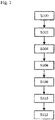
- Fig. 1 depicts an embodiment of a joining method S100 - S112.
- the method joins a workpiece 10 and a component 12 together.
- the workpiece 10 is preferably an aircraft structure to which typically multiple smaller components are attached.
- Examples for the workpiece 10 include (a part of) a fuselage, a wing or wing box, a tail plane or the like.
- Examples for the component include brackets, clips, ribs, and (corner) fittings.
- the component 12 is provided for further processing.
- the component 12 is configured to be joined to the workpiece 10.
- the component 12 includes a joining portion 14.
- the component 12 - including the joining portion 14 - is manufactured with final dimensions.
- the joining portion 14 has a plurality of joining holes 16 for joining the joining portion 14 to the workpiece 10. It should be noted that other joining features are possible, in particular in addition to the joining holes 16. Furthermore it is possible for the component 12 to have more than one joining portion 14.
- the component 12 has associated with it at least one first geometric datum G1.
- the first geometric datum G1 is indicative of a manufactured geometric property of the joining portion 14.
- the joining portion 14 may include four joining holes 16 that are arranged on the corners of a square, as illustrated in more detail in Fig. 2 .
- the first geometric data G1 include the final size joining hole diameter of each joining hole 16.
- the first geometric data G1 include the relative positions of the joining holes 16.
- the first geometric data G1 are indicative of the exact hole pattern of the joining portion 14. More general, the first geometric data G1 are indicative of the exact configuration of the joining portion 14.
- Each first geometric datum G1 is obtained by means of an automatic measuring process, such as photogrammetry and/or laser scanning.
- the first geometric data G1 are stored in a machine readable form in a data storage 20.
- the data storage 20 is preferably a tag 22 that may be attached to the component 12 or is delivered together with the component 12.
- the tag 22 may be selected from a group including 1-D or 2-D barcode tags or RFID-tags.
- the data storage 20 may include a database that stores the first geometric data G1 corresponding to the respective component 12.
- a positioning step S102 the component 12 is positioned in a predetermined position.
- the first geometric data G1 may be used to position the component 12.
- the component 12 may be prefixed using a sealant.
- a shim 24 may be arranged between the workpiece 10 and the component 12. In this case, the whole stack of parts including the shim 24 can be prefixed using the sealant.
- a machine tool device 26 is used for working on the workpiece 10.
- the machine tool device 26 is an automatic drilling device 28 configured for automatically drilling holes at predetermined positions using numerical control.
- the component 12 and the machine tool device 26 are positioned on opposite sides of the workpiece 10.
- the machine tool device 26 comprises a measuring device 30.
- the measuring device 30 is configured for measuring the component 12, in particular the joining portion 14.
- the measuring device 30 has a measuring unit 31 that is configured such that measuring can be performed through the workpiece 10.
- the measuring unit 31 may include an ultrasonic measuring head 32.
- the measuring unit 31 may also use other methods, for example a magnetic measuring head based on magnetic principles.
- the machine tool device 26 further includes a tool 34.
- the tool 34 is a drilling tool 36.
- the machine tool device 26 has a control device 38 that is configured for controlling the operations of the machine tool device 26, among them positioning and operating the tool 34.
- the measuring device 30 measures the relative position and joining hole diameter of every joining hole 16 of the component. For example, the measuring device 30 sends out pulses of ultrasonic waves and detects the reflection. In a manner known per se, the layered structure ( Fig. 4 ) of the joint to be is measured. As a result the positioning and joining hole diameter of each joining hole 16 is determined as second geometric data G2.
- the second geometric data G2 thus include information corresponding to the first geometric data G1.
- the second geometric data G2 are obtained from a source independent from the source of the first geometric data G1.
- the second geometric data G2 are stored in the control device 38.
- a comparing step S106 the control device 38 retrieves the first geometric data G1 from the data storage 20 and compares it to the second geometric data G2. A deviation between the first and second geometric data, G1, G2 is determined.
- a positioning step S108 and an operating step S110 are performed.
- the control device 38 causes the tool 34 to move to a working position given by the first and/or second geometric data G1, G2.
- the operating step S110 the control device 38 causes the tool 34 to perform a tool operation.
- the drilling tool 36 is moved to the drilling positions that correspond to the positions of the joining holes 16 and the drilling tool 36 drills through the workpiece 10 and the joining holes 16. Since a small deviation in joining hole diameter and relative position is allowed, the drilling tool 36 may also remove a small amount of the component 12.
- a fastening step S112 fasteners are inserted into the previously drilled holes. Subsequently, the component 12 is fastened to the workpiece 10 using the fasteners.
- control device 38 may record all steps in order to obtain a continuous record of the manufacturing process for quality control and other documentation purposes.
- the steps S100 to S106 form a positioning method for positioning a tool.
- the steps S100 to S110 form a general machining method in case of a machine tool device and specifically a drilling method in case of an automatic drilling device.
- a drilling method is provided that allows drilling in confined spaces with less effort.
- the idea is to use two independent data sources for reducing the tolerances between the component to be joined to the workpiece.
- the component is measured at the supplier using photogrammetry or laser scanning.
- First geometric data of the component obtained by this measurement are put in a data storage, such as a barcode tag or database.
- the first geometric data are used to position the component relative to the workpiece.
- the component is measured to obtain second geometric data that are indicative of the positions and diameters of the joining holes of the component.
- the automatic drill is positioned at the correct drilling location and joining holes are drilled into the workpiece. Finally, the component and the workpiece are joined by fasteners.
Landscapes
- Engineering & Computer Science (AREA)
- Mechanical Engineering (AREA)
- Human Computer Interaction (AREA)
- Manufacturing & Machinery (AREA)
- Physics & Mathematics (AREA)
- General Physics & Mathematics (AREA)
- Automation & Control Theory (AREA)
- Drilling And Boring (AREA)
Abstract
Description
- The invention relates to methods for a machine tool device, a machine tool device and a computer program product.
- Manufacturing today, in particular in the aircraft industry, is based on an intricate supply chains using different suppliers who manufacture parts according to given specifications. Usually for compatibility reasons, the parts are not completely finished but have to be finished and fitted at the assembly line of the aircraft manufacturer, for example.
- In some assembly steps, structural parts, such as ribs, brackets, corner fittings and the like, need to be arranged in confined spaces or other situations in which the part is not easily accessible for work. However, the part still needs to be finished and fitted before it can be mounted in its predetermined position.
- It is the object of the invention to reduce the time and/or effort required for assembly.
- The invention provides a positioning method for automatically positioning a tool of a machine tool device relative to a workpiece and a component, wherein the machine tool device comprises a measuring device and a control device. The positioning method comprises the steps of:
- 1.1 Providing a component to be assembled which is manufactured to final dimension, including all assembly holes required for joining the component to the workpiece. Furthermore, all relevant dimensional data for each individual component is to be physically marked on the component in a machine readable form. These dimensional data are to be measured at the supplier of the component to the maximum accuracy possible.
- 1.2 Positioning the component relative to required position based on the geometrical information read from the component and relevant datum positions in the area in which the component is to be mounted.
- 1.3 Using a measurement system, which uses the information on the component and the geometrical description of the area in which the part is mounted to confirm that the part has been positioned in the required position.
- 1.4 The machine tool to drill any required holes is mounted in the most convenient position, which will often be on the exterior of the area to be drilled. The part to be assembled is then scanned from the position of the machine tool through the structure to be drilled.
- 1.5 The information from this scan is then compared to the geometrical data provided with the component. If the two independent measurements of each hole to be drilled agree to the accuracy of a pre-determined threshold, then the machine tool device will be controlled by the local data defining the position at which each drilling operation is to take place.
- The information for the part to be assembled should include at least three assembly holes and their exact diameters, together with the relative positions of these holes. Additional information on the position and angle of mating surfaces within the component should also be available.
- Preferably, the data storage includes a tag that is configured to be attached to the component, such as a barcode tag, a 2D-barcode tag and/or an RFID-tag. The information about drawing number and individual component number must be included within the data storage.
- The measuring device should includes a measuring unit that is configured to detect geometric dimensions of the component to be joined, when the component and the measuring unit are arranged on opposite sides of the structure to be drilled.
- As an example, the measuring unit may use an ultrasonic measuring head, and the second geometric datum is measured by means of ultrasonic waves. It is important that this measurement system does not require any water or other medium to correctly function. Such systems are relatively new, but do exist in the market today.
- Preferably, the positioning method further comprises the step of:
1.6 Removing the component, if the deviation is determined to be above a pre-determined threshold. - The invention provides a machining method for machining a workpiece and/or a component using a machine tool device, the machining method comprising the steps of:
- 8.1 with the machine tool device, performing a preferred positioning method; and
- 8.2 after step 8.1, performing an operation with the tool on the workpiece and/or on the component at the predetermined working position.
- The invention provides a drilling method for a machine tool device configured for automatically drilling holes into a workpiece so as to allow joining of the workpiece with a component, the drilling method comprising the steps of:
- 9.1 with the machine tool device, performing a preferred positioning method, wherein the tool is a drilling tool; and
- 9.2 Drilling a hole at the predetermined position.
- The invention provides a joining method for joining a workpiece and a component, the joining method comprising:
- 10.1 performing a preferred drilling method; and
- 10.2 Inserting a fastener into the bored hole and fastening the workpiece and the component using the fastener.
- The invention provides computer program for a machine tool device having a tool configured for machining the workpiece, a measuring device configured for measuring the component, and a control device, wherein the computer program comprises instructions which, when the program is executed by the control device cause the machine tool device to perform any of the methods described before.
- The invention provides a computer readable medium comprising the preferred computer program.
- The invention provides a data carrier signal carrying the preferred computer program.
- The invention provides a machine tool device configured for machining a workpiece based on a component that is arranged to be attached to the workpiece, wherein the machine tool device comprises a tool configured for machining the workpiece, a measuring device configured for measuring the component, and a control device configured to control the machine tool device such that any of the preferred methods described before is performed.
- Preferably, the machine tool device is an automatic drilling device and the tool is a drilling tool.
- With the invention, drilling or drilling from inside confined spaces may be improved. In particular required time and effort may be decreased. Usually, drilling of multiple material stacks (e.g. carbon-fiber reinforced plastic, CFRP, and Titanium) compromises drilling speeds for both materials. The methods and devices according to the invention help to avoid repeated drilling of holes, thereby decreasing wear and increasing tool life. Furthermore, the use of shims is simplified. The shims may be introduced between the workpiece and the component before drilling.
- Furthermore, the invention avoids the use of drilling templates. As a result, smaller improvements of the overall construction may readily be implemented since time consuming reconstruction of drilling templates can be omitted.
- In addition, time consuming disassembly and reassembly due to burrs, especially on brittle Titanium and the like, can be avoided.
- According to the invention no pilot or positioning holes are drilled in the workpiece. The components to be installed on the aircraft are predrilled to final diameter by the supplier. Extremely highly loaded components (in general less than 5 %) are preferably drilled with the diameter 0.1 mm undersize.
- Each component is automatically measured at the supplier using photogrammetry, for example. Other contactless methods such as laser scanning may also be used. Information of manufactured geometric properties such as exact diameter and position of every hole relative to each other, datum faces and interface points are added to the component in machine readable form. This may take the form of a 2-D bar code, simple barcode or database entry.
- The component is then positioned at the manufacturer using the machine readable geometric data, e.g. by scanning the 2-D barcode. The component may be prefixed to the workpiece together with sealant and/or a shim as necessary.
- Whilst the sealant is curing, the component is scanned through the workpiece to be drilled, such as the aircraft structure. The scanning can be done by means of (waterless) ultrasonic waves or other means that allow scanning of the component through the workpiece, magnetic means for example. The results of the scan are compared with the data delivered with the component, i.e. the barcode or database entry. If the data provided by the supplier and the data measured by the manufacturer are consistent, i.e. are within a predetermined threshold, the automatic drilling device is updated in real-time.
- Subsequently, the automatic drilling system drills the holes from the outside at a convenient angle - no further work required.
- With the methods and devices described herein, an accuracy of 0.1 mm may be achieved. The wear on the drilling tools may be reduced, in particular in the case of mixed material joints (CFRP and Titanium). The overall time required for drilling can be reduced.
- In addition, the use of shims may be reduced or entirely avoided thereby reducing delays for individual fitting of parts. Also removal of burrs - and disassembly and reassembly in connection therewith - may be avoided. As a result the assembly rate may increase.
- It is also possible to create an automatic inspection and quality documentation record based on the measurements. Finally, the need for work in enclosed or confined spaces is reduced thereby improving ergonomics.
- Embodiments of the invention are described in more detail with reference to the accompanying schematic drawings.
- Fig. 1
- illustrates an embodiment of a joining method;
- Fig. 2
- illustrates an example of a typical joining situation;
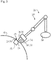
- Fig. 3
- depicts an embodiment of a machine tool device; and
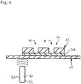
- Fig. 4
- depicts a cross-section of the joining situation.
- Reference is made to
Fig. 1 which depicts an embodiment of a joining method S100 - S112. The method joins aworkpiece 10 and acomponent 12 together. Theworkpiece 10 is preferably an aircraft structure to which typically multiple smaller components are attached. Examples for theworkpiece 10 include (a part of) a fuselage, a wing or wing box, a tail plane or the like. Examples for the component include brackets, clips, ribs, and (corner) fittings. - In an initial step S100, also designated providing step, the
component 12 is provided for further processing. Thecomponent 12 is configured to be joined to theworkpiece 10. Thecomponent 12 includes a joiningportion 14. The component 12 - including the joining portion 14 - is manufactured with final dimensions. - The joining
portion 14 has a plurality of joiningholes 16 for joining the joiningportion 14 to theworkpiece 10. It should be noted that other joining features are possible, in particular in addition to the joining holes 16. Furthermore it is possible for thecomponent 12 to have more than one joiningportion 14. - The
component 12 has associated with it at least one first geometric datum G1. The first geometric datum G1 is indicative of a manufactured geometric property of the joiningportion 14. - For example, the joining
portion 14 may include four joiningholes 16 that are arranged on the corners of a square, as illustrated in more detail inFig. 2 . The first geometric data G1 include the final size joining hole diameter of each joininghole 16. Furthermore, the first geometric data G1 include the relative positions of the joining holes 16. In other words, the first geometric data G1 are indicative of the exact hole pattern of the joiningportion 14. More general, the first geometric data G1 are indicative of the exact configuration of the joiningportion 14. - Each first geometric datum G1 is obtained by means of an automatic measuring process, such as photogrammetry and/or laser scanning. The first geometric data G1 are stored in a machine readable form in a data storage 20.
- The data storage 20 is preferably a tag 22 that may be attached to the
component 12 or is delivered together with thecomponent 12. The tag 22 may be selected from a group including 1-D or 2-D barcode tags or RFID-tags. In another embodiment, the data storage 20 may include a database that stores the first geometric data G1 corresponding to therespective component 12. - In a positioning step S102, the
component 12 is positioned in a predetermined position. During the positioning the first geometric data G1 may be used to position thecomponent 12. Thecomponent 12 may be prefixed using a sealant. In addition, ashim 24 may be arranged between the workpiece 10 and thecomponent 12. In this case, the whole stack of parts including theshim 24 can be prefixed using the sealant. - A
machine tool device 26 is used for working on theworkpiece 10. In this embodiment, themachine tool device 26 is anautomatic drilling device 28 configured for automatically drilling holes at predetermined positions using numerical control. Usually, as depicted inFig. 3 , thecomponent 12 and themachine tool device 26 are positioned on opposite sides of theworkpiece 10. - The
machine tool device 26 comprises a measuring device 30. The measuring device 30 is configured for measuring thecomponent 12, in particular the joiningportion 14. The measuring device 30 has a measuringunit 31 that is configured such that measuring can be performed through theworkpiece 10. The measuringunit 31 may include anultrasonic measuring head 32. The measuringunit 31 may also use other methods, for example a magnetic measuring head based on magnetic principles. - The
machine tool device 26 further includes a tool 34. In case of theautomatic drilling device 28, the tool 34 is a drilling tool 36. - The
machine tool device 26 has acontrol device 38 that is configured for controlling the operations of themachine tool device 26, among them positioning and operating the tool 34. - In a measuring step S104, the measuring device 30 measures the relative position and joining hole diameter of every joining
hole 16 of the component. For example, the measuring device 30 sends out pulses of ultrasonic waves and detects the reflection. In a manner known per se, the layered structure (Fig. 4 ) of the joint to be is measured. As a result the positioning and joining hole diameter of each joininghole 16 is determined as second geometric data G2. The second geometric data G2 thus include information corresponding to the first geometric data G1. The second geometric data G2 are obtained from a source independent from the source of the first geometric data G1. The second geometric data G2 are stored in thecontrol device 38. - In a comparing step S106, the
control device 38 retrieves the first geometric data G1 from the data storage 20 and compares it to the second geometric data G2. A deviation between the first and second geometric data, G1, G2 is determined. - If the deviation is below a predetermined threshold, a positioning step S108 and an operating step S110 are performed. In the positioning step S108, the
control device 38 causes the tool 34 to move to a working position given by the first and/or second geometric data G1, G2. In the operating step S110, thecontrol device 38 causes the tool 34 to perform a tool operation. - In case of the
automatic drilling device 28, the drilling tool 36 is moved to the drilling positions that correspond to the positions of the joiningholes 16 and the drilling tool 36 drills through theworkpiece 10 and the joining holes 16. Since a small deviation in joining hole diameter and relative position is allowed, the drilling tool 36 may also remove a small amount of thecomponent 12. - In a fastening step S112, fasteners are inserted into the previously drilled holes. Subsequently, the
component 12 is fastened to theworkpiece 10 using the fasteners. - If the deviation exceeds the predetermined threshold, none of the steps S108 to S112 are performed. Instead, the
component 12 is removed and rejected as out of spec. - It should be noted that all steps may be recorded by the
control device 38 in order to obtain a continuous record of the manufacturing process for quality control and other documentation purposes. - The steps S100 to S106 form a positioning method for positioning a tool. The steps S100 to S110 form a general machining method in case of a machine tool device and specifically a drilling method in case of an automatic drilling device.
- In order to improve manufacturing of aircraft, a drilling method is provided that allows drilling in confined spaces with less effort. The idea is to use two independent data sources for reducing the tolerances between the component to be joined to the workpiece. The component is measured at the supplier using photogrammetry or laser scanning. First geometric data of the component obtained by this measurement are put in a data storage, such as a barcode tag or database. At the manufacturer, the first geometric data are used to position the component relative to the workpiece. Subsequently, the component is measured to obtain second geometric data that are indicative of the positions and diameters of the joining holes of the component. After determining a deviation between the first and second geometric data to be smaller than a predetermined threshold, the automatic drill is positioned at the correct drilling location and joining holes are drilled into the workpiece. Finally, the component and the workpiece are joined by fasteners.
-
- 10
- workpiece
- 12
- component
- 14
- joining portion
- 16
- joining holes
- 20
- data storage
- 22
- tag
- 24
- shim
- 26
- machine tool device
- 28
- automatic drilling device
- 30
- measuring device
- 31
- measuring unit
- 32
- ultrasonic measuring head
- 34
- tool
- 36
- drill
- 38
- control device
- G1
- first geometric datum
- G2
- second geometric data
- S100
- initial step
- S102
- positioning step
- S104
- measuring step
- S106
- comparing step
- S108
- positioning step
- S110
- operating step
Claims (15)
- A positioning method for automatically positioning a tool (34) of a machine tool device (26) relative to a workpiece (10) and a component (12), wherein the machine tool device (26) comprises a measuring device (30) and a control device (38), wherein the positioning method comprises the steps of:1.1 Providing a component (12) having a joining portion (14), wherein the joining portion (14) is manufactured to final dimension and is configured for joining the component (12) to the workpiece (10), wherein the component (12) has associated with it at least one first geometric datum (G1) indicative of a manufactured geometric property of the joining portion (14), wherein the first geometric datum (G1) is stored in machine readable form in a data storage (20);1.2 Positioning the component (12) relative to the workpiece (10) in a predetermined position based on the first geometric datum (G1);1.3 with the measuring device (30), measuring the joining portion (14) after the component (12) was arranged at the predetermined position so as to obtain at least one second measured geometric datum (G2) that corresponds to the respective first measured geometric datum (G1) stored in the data storage (20);1.4 with the control device (38), retrieving the first measured geometric datum (G1) from the data storage (20) and determining a deviation between the retrieved first measured geometric datum (G1) and the second measured geometric datum (G2); and1.5 with the control device (38), controlling the machine tool device (26) such that the tool (34) is moved to a predetermined working position, if the deviation is determined to be below a predetermined threshold.
- Positioning method according to claim 1, wherein the joining portion (14) includes at least one joining hole (16), and the first geometric datum (G1) is indicative of a manufactured joining hole position and/or a manufactured joining hole diameter.
- The positioning method according to any of the preceding claims, wherein the data storage (20) includes any of a tag (22) that is configured to be attached to the component (12), such as a barcode tag, a 2D-barcode tag and/or an RFID-tag, and/or a database.
- The positioning method according to any of the preceding claims, wherein the measuring device (30) includes a measuring unit (31) that is configured to detect geometric dimensions of the component (12), when the component (12) and the measuring unit (31) are arranged on opposite sides of the workpiece (10), and the second geometric datum (G2) is measured by means of the measuring unit (31).
- The positioning method according to claim 4, wherein the measuring unit (31) is configured as an ultrasonic measuring head (32), and the second geometric datum (G2) is measured by means of ultrasonic waves.
- The positioning method according to any of the claims 2 to 5, wherein the second geometric datum (G2) includes a measured joining hole position that corresponds to a manufactured joining hole position and/or a measured joining hole diameter that corresponds to a manufactured joining hole diameter.
- The positioning method according to any of the preceding claims, further comprising the step of:
1.6 Removing the component (12), if the deviation is determined to be above a predetermined threshold. - A machining method for machining a workpiece (10) and/or a component (12) using a machine tool device (26), the machining method comprising the steps of:8.1 with the machine tool device (26), performing a positioning method according to any of the claims 1 to 7; and8.2 after step 8.1, performing an operation with the tool (34) on the workpiece (10) and/or on the component (12) at the predetermined working position.
- A drilling method for a machine tool device (26) configured for automatically drilling holes into a workpiece (10) so as to allow joining of the workpiece (10) with a component (12), the drilling method comprising the steps of:9.1 with the machine tool device (26), performing a positioning method according to any of the claims 1 to 7, wherein the tool (34) is a drilling tool (36); and9.2 Drilling a hole at the predetermined position.
- A joining method for joining a workpiece (10) and a component (12), the joining method comprising:10.1 performing a drilling method according to claim 9; and10.2 Inserting a fastener into the bored hole and fastening the workpiece (10) and the component (12) using the fastener.
- A computer program for a machine tool device (26) having a tool (34) configured for machining the workpiece (10), a measuring device (30) configured for measuring the component (12), and a control device (38), wherein the computer program comprises instructions which, when the program is executed by the control device (38) cause the machine tool device (26) to perform a method according to any of the preceding claims.
- A computer readable medium comprising the computer program according to claim 11.
- A data carrier signal carrying the computer program according to claim 11.
- A machine tool device (26) configured for machining a workpiece (10) based on a component (12) that is arranged to be attached to the workpiece (10), wherein the machine tool device (26) comprises a tool (34) configured for machining the workpiece (10), a measuring device (30) configured for measuring the component (12), and a control device (38) configured to control the machine tool device (26) such that a method according to any of the claims 1 to 10 is performed.
- The machine tool device (26) according to claim 14, wherein the machine tool device (26) is an automatic drilling device (28) and the tool (34) is a drilling tool (36).
Priority Applications (2)
| Application Number | Priority Date | Filing Date | Title |
|---|---|---|---|
| EP20215056.1A EP4016210A1 (en) | 2020-12-17 | 2020-12-17 | Positioning-, drilling-, and joining methods for a machine tool device |
| US17/550,823 US11899422B2 (en) | 2020-12-17 | 2021-12-14 | Positioning-, drilling-, and joining methods for a machine tool device |
Applications Claiming Priority (1)
| Application Number | Priority Date | Filing Date | Title |
|---|---|---|---|
| EP20215056.1A EP4016210A1 (en) | 2020-12-17 | 2020-12-17 | Positioning-, drilling-, and joining methods for a machine tool device |
Publications (1)
| Publication Number | Publication Date |
|---|---|
| EP4016210A1 true EP4016210A1 (en) | 2022-06-22 |
Family
ID=73855371
Family Applications (1)
| Application Number | Title | Priority Date | Filing Date |
|---|---|---|---|
| EP20215056.1A Withdrawn EP4016210A1 (en) | 2020-12-17 | 2020-12-17 | Positioning-, drilling-, and joining methods for a machine tool device |
Country Status (2)
| Country | Link |
|---|---|
| US (1) | US11899422B2 (en) |
| EP (1) | EP4016210A1 (en) |
Cited By (1)
| Publication number | Priority date | Publication date | Assignee | Title |
|---|---|---|---|---|
| EP4714588A1 (en) * | 2024-09-19 | 2026-03-25 | Airbus Operations, S.L.U. | Method for assembling parts |
Citations (2)
| Publication number | Priority date | Publication date | Assignee | Title |
|---|---|---|---|---|
| US20200101541A1 (en) * | 2018-09-28 | 2020-04-02 | The Boeing Company | Replicated hole pattern for remotely located structural components |
| US20200346349A1 (en) * | 2019-04-30 | 2020-11-05 | Flexiv Ltd. | Robot-based insertion mounting of workpieces |
Family Cites Families (30)
| Publication number | Priority date | Publication date | Assignee | Title |
|---|---|---|---|---|
| JPS5577434A (en) * | 1978-11-27 | 1980-06-11 | Nissan Motor Co Ltd | Car assembly control system |
| JPS59124469A (en) * | 1982-12-28 | 1984-07-18 | Nissan Motor Co Ltd | Production control system |
| AR022299A1 (en) * | 1999-01-29 | 2002-09-04 | Sensormatic Electronics Corp | PRODUCTION AND OPERATION MANAGEMENT USING READING / WRITING RFID LABELS |
| DE19908706A1 (en) * | 1999-02-26 | 2000-11-02 | Werth Messtechnik Gmbh | Method for determining the deviations of the geometric dimensions and / or the position of an object from predeterminable target values of the geometric dimensions and / or the position of the object |
| JP2003296679A (en) * | 2002-03-29 | 2003-10-17 | Nippon Steel Corp | Tag, information processing device, metal material and / or metal product management system, metal material and / or metal product management method, storage medium, and program |
| GB0210990D0 (en) * | 2002-05-14 | 2002-06-19 | Rolls Royce Plc | Method of generating an inspection program and method of generating a visual display |
| US7725206B2 (en) * | 2003-11-12 | 2010-05-25 | The Boeing Company | System and method for manufacturing and after-market support using as-built data |
| JP2006053670A (en) * | 2004-08-10 | 2006-02-23 | Ntn Corp | Quality control method for aerospace machine element products and bearing for aerospace |
| US7287694B2 (en) * | 2004-08-25 | 2007-10-30 | International Business Machines Corporation | Method and system for context-based automated product identification and verification |
| US20080189325A1 (en) * | 2006-10-31 | 2008-08-07 | Electronic Data Systems Corporation | Intelligent Assembly System and Method of Use |
| US8447549B2 (en) * | 2011-02-11 | 2013-05-21 | Quality Vision International, Inc. | Tolerance evaluation with reduced measured points |
| JP6099675B2 (en) * | 2012-01-27 | 2017-03-22 | ファロ テクノロジーズ インコーポレーテッド | Inspection method by barcode identification |
| US20140067333A1 (en) * | 2012-09-04 | 2014-03-06 | Belcan Corporation | CAD-Based System for Product Definition, Inspection and Validation |
| US8970233B2 (en) * | 2012-11-12 | 2015-03-03 | Spirit Aerosystems, Inc. | Nondestructive inspection system controller with dynamic position correction |
| US9187188B2 (en) * | 2013-07-02 | 2015-11-17 | Premium Aerotec Gmbh | Assembly inspection system and method |
| US9558547B2 (en) * | 2014-01-09 | 2017-01-31 | The Boeing Company | System and method for determining whether an apparatus or an assembly process is acceptable |
| US20160033251A1 (en) * | 2014-07-29 | 2016-02-04 | Plethora Corporation | System and method for automated object measurement |
| WO2016046729A1 (en) * | 2014-09-25 | 2016-03-31 | Bombardier Inc. | Inspection tool for manufactured components |
| GB201418349D0 (en) * | 2014-10-16 | 2014-12-03 | Rolls Royce Plc | Virtual component alignment |
| GB2540374A (en) * | 2015-07-14 | 2017-01-18 | Airbus Operations Ltd | Machine tool control & measurement system |
| US9952580B2 (en) * | 2016-01-29 | 2018-04-24 | The Boeing Company | Method and an apparatus for machining a part for an assembly |
| JP6568500B2 (en) * | 2016-04-28 | 2019-08-28 | 川崎重工業株式会社 | Component mounting system and component mounting method |
| DE102016209557B4 (en) * | 2016-06-01 | 2022-03-31 | Carl Zeiss Industrielle Messtechnik Gmbh | Method for identifying a workpiece, determining a measurement sequence and measuring a workpiece with a measuring device |
| US10934020B2 (en) * | 2017-01-25 | 2021-03-02 | The Boeing Company | Method and system for joining structures |
| ES2713963B2 (en) * | 2017-11-17 | 2021-01-07 | Airbus Defence And Space Sau | Manufacturing and assembly method and system of parts of an aircraft |
| DE102018204259A1 (en) * | 2018-03-20 | 2019-09-26 | Siemens Aktiengesellschaft | Method for producing a coded component and component with a code |
| US10843821B2 (en) * | 2019-01-03 | 2020-11-24 | The Boeing Company | Predictive preparation of material for joint assembly |
| WO2020252187A1 (en) * | 2019-06-11 | 2020-12-17 | Cameron International Corporation | Virtual integration test system and method |
| JP7481829B2 (en) * | 2019-11-11 | 2024-05-13 | 株式会社Subaru | Assembly Equipment |
| EP3876147A1 (en) * | 2020-03-04 | 2021-09-08 | United States Postal Service | Automatically measuring an item based on a ratio between item dimensions and reference tag dimensions |
-
2020
- 2020-12-17 EP EP20215056.1A patent/EP4016210A1/en not_active Withdrawn
-
2021
- 2021-12-14 US US17/550,823 patent/US11899422B2/en active Active
Patent Citations (2)
| Publication number | Priority date | Publication date | Assignee | Title |
|---|---|---|---|---|
| US20200101541A1 (en) * | 2018-09-28 | 2020-04-02 | The Boeing Company | Replicated hole pattern for remotely located structural components |
| US20200346349A1 (en) * | 2019-04-30 | 2020-11-05 | Flexiv Ltd. | Robot-based insertion mounting of workpieces |
Cited By (1)
| Publication number | Priority date | Publication date | Assignee | Title |
|---|---|---|---|---|
| EP4714588A1 (en) * | 2024-09-19 | 2026-03-25 | Airbus Operations, S.L.U. | Method for assembling parts |
Also Published As
| Publication number | Publication date |
|---|---|
| US20220197241A1 (en) | 2022-06-23 |
| US11899422B2 (en) | 2024-02-13 |
Similar Documents
| Publication | Publication Date | Title |
|---|---|---|
| US11370563B2 (en) | Method and system for joining structures | |
| Jamshidi et al. | Manufacturing and assembly automation by integrated metrology systems for aircraft wing fabrication | |
| US8005567B2 (en) | Method and control system for generating machine tool control data | |
| Muelaner et al. | Achieving low cost and high quality aero structure assembly through integrated digital metrology systems | |
| US9483047B2 (en) | System and method for operating a machine and performing quality assurance | |
| EP2370869B1 (en) | Conforming components using reverse engineering | |
| US11899422B2 (en) | Positioning-, drilling-, and joining methods for a machine tool device | |
| US10899476B1 (en) | Model-based definition for machining aircraft parts | |
| US20020166220A1 (en) | Process for repairing a structure | |
| CN112513943A (en) | System and method for manufactured product dynamic measurement, tool selection, and tool path generation | |
| CN108705381B (en) | Alignment method and alignment device for numerical control machining of deep groove side holes | |
| US20060293906A1 (en) | Method of developing a plan for replacing a product component using a scanning process | |
| Mir et al. | 777X control surface assembly using advanced robotic automation | |
| Dimitrov et al. | Accuracy and reliability control of machining operations on machining centres | |
| Durham | Determining appropriate levels of robotic automation in commercial aircraft nacelle assembly | |
| Oberoi et al. | Production implementation of a multi spindle flexible drilling system for circumferential splice drilling applications on the 777 airplane | |
| CN114643477B (en) | Modular additive manufacturing tool assembly | |
| Dimitrov et al. | System for controlling the accuracy and reliability of machining operations on machining centres | |
| KR102698345B1 (en) | Control method and control system for machine tool | |
| Ma et al. | Quantitative analysis and improvement of countersink depth in stack drilling | |
| Coleman | The effects of design, manufacturing processes and operations management on the assembly of aircraft composite structure | |
| Hollingum | Renishaw automate programming and machining to micron accuracy | |
| Smith | Development of temporary blind auto fasteners | |
| Proctor | Controls And Sensors For Advanced Manufacturing | |
| CN120634768A (en) | A digital model of manufacturing resources |
Legal Events
| Date | Code | Title | Description |
|---|---|---|---|
| PUAI | Public reference made under article 153(3) epc to a published international application that has entered the european phase |
Free format text: ORIGINAL CODE: 0009012 |
|
| STAA | Information on the status of an ep patent application or granted ep patent |
Free format text: STATUS: THE APPLICATION HAS BEEN PUBLISHED |
|
| AK | Designated contracting states |
Kind code of ref document: A1 Designated state(s): AL AT BE BG CH CY CZ DE DK EE ES FI FR GB GR HR HU IE IS IT LI LT LU LV MC MK MT NL NO PL PT RO RS SE SI SK SM TR |
|
| STAA | Information on the status of an ep patent application or granted ep patent |
Free format text: STATUS: REQUEST FOR EXAMINATION WAS MADE |
|
| 17P | Request for examination filed |
Effective date: 20221222 |
|
| RBV | Designated contracting states (corrected) |
Designated state(s): AL AT BE BG CH CY CZ DE DK EE ES FI FR GB GR HR HU IE IS IT LI LT LU LV MC MK MT NL NO PL PT RO RS SE SI SK SM TR |
|
| STAA | Information on the status of an ep patent application or granted ep patent |
Free format text: STATUS: EXAMINATION IS IN PROGRESS |
|
| 17Q | First examination report despatched |
Effective date: 20240528 |
|
| STAA | Information on the status of an ep patent application or granted ep patent |
Free format text: STATUS: THE APPLICATION IS DEEMED TO BE WITHDRAWN |
|
| 18D | Application deemed to be withdrawn |
Effective date: 20250613 |