EP4016160A1 - Optical device with a folded optical path - Google Patents
Optical device with a folded optical path Download PDFInfo
- Publication number
- EP4016160A1 EP4016160A1 EP21199557.6A EP21199557A EP4016160A1 EP 4016160 A1 EP4016160 A1 EP 4016160A1 EP 21199557 A EP21199557 A EP 21199557A EP 4016160 A1 EP4016160 A1 EP 4016160A1
- Authority
- EP
- European Patent Office
- Prior art keywords
- optical
- filter
- light
- aperture
- diffused light
- Prior art date
- Legal status (The legal status is an assumption and is not a legal conclusion. Google has not performed a legal analysis and makes no representation as to the accuracy of the status listed.)
- Pending
Links
Images



Classifications
-
- G—PHYSICS
- G01—MEASURING; TESTING
- G01J—MEASUREMENT OF INTENSITY, VELOCITY, SPECTRAL CONTENT, POLARISATION, PHASE OR PULSE CHARACTERISTICS OF INFRARED, VISIBLE OR ULTRAVIOLET LIGHT; COLORIMETRY; RADIATION PYROMETRY
- G01J3/00—Spectrometry; Spectrophotometry; Monochromators; Measuring colours
- G01J3/46—Measurement of colour; Colour measuring devices, e.g. colorimeters
- G01J3/50—Measurement of colour; Colour measuring devices, e.g. colorimeters using electric radiation detectors
-
- G—PHYSICS
- G01—MEASURING; TESTING
- G01D—MEASURING NOT SPECIALLY ADAPTED FOR A SPECIFIC VARIABLE; ARRANGEMENTS FOR MEASURING TWO OR MORE VARIABLES NOT COVERED IN A SINGLE OTHER SUBCLASS; TARIFF METERING APPARATUS; MEASURING OR TESTING NOT OTHERWISE PROVIDED FOR
- G01D5/00—Mechanical means for transferring the output of a sensing member; Means for converting the output of a sensing member to another variable where the form or nature of the sensing member does not constrain the means for converting; Transducers not specially adapted for a specific variable
- G01D5/26—Mechanical means for transferring the output of a sensing member; Means for converting the output of a sensing member to another variable where the form or nature of the sensing member does not constrain the means for converting; Transducers not specially adapted for a specific variable characterised by optical transfer means, i.e. using infrared, visible, or ultraviolet light
-
- G—PHYSICS
- G02—OPTICS
- G02B—OPTICAL ELEMENTS, SYSTEMS OR APPARATUS
- G02B19/00—Condensers, e.g. light collectors or similar non-imaging optics
- G02B19/0004—Condensers, e.g. light collectors or similar non-imaging optics characterised by the optical means employed
- G02B19/0019—Condensers, e.g. light collectors or similar non-imaging optics characterised by the optical means employed having reflective surfaces only (e.g. louvre systems, systems with multiple planar reflectors)
-
- G—PHYSICS
- G02—OPTICS
- G02B—OPTICAL ELEMENTS, SYSTEMS OR APPARATUS
- G02B5/00—Optical elements other than lenses
- G02B5/20—Filters
-
- G—PHYSICS
- G01—MEASURING; TESTING
- G01J—MEASUREMENT OF INTENSITY, VELOCITY, SPECTRAL CONTENT, POLARISATION, PHASE OR PULSE CHARACTERISTICS OF INFRARED, VISIBLE OR ULTRAVIOLET LIGHT; COLORIMETRY; RADIATION PYROMETRY
- G01J3/00—Spectrometry; Spectrophotometry; Monochromators; Measuring colours
- G01J3/02—Details
- G01J3/0205—Optical elements not provided otherwise, e.g. optical manifolds, diffusers, windows
-
- G—PHYSICS
- G01—MEASURING; TESTING
- G01J—MEASUREMENT OF INTENSITY, VELOCITY, SPECTRAL CONTENT, POLARISATION, PHASE OR PULSE CHARACTERISTICS OF INFRARED, VISIBLE OR ULTRAVIOLET LIGHT; COLORIMETRY; RADIATION PYROMETRY
- G01J3/00—Spectrometry; Spectrophotometry; Monochromators; Measuring colours
- G01J3/02—Details
- G01J3/0205—Optical elements not provided otherwise, e.g. optical manifolds, diffusers, windows
- G01J3/021—Optical elements not provided otherwise, e.g. optical manifolds, diffusers, windows using plane or convex mirrors, parallel phase plates, or particular reflectors
-
- G—PHYSICS
- G01—MEASURING; TESTING
- G01J—MEASUREMENT OF INTENSITY, VELOCITY, SPECTRAL CONTENT, POLARISATION, PHASE OR PULSE CHARACTERISTICS OF INFRARED, VISIBLE OR ULTRAVIOLET LIGHT; COLORIMETRY; RADIATION PYROMETRY
- G01J3/00—Spectrometry; Spectrophotometry; Monochromators; Measuring colours
- G01J3/02—Details
- G01J3/0256—Compact construction
-
- G—PHYSICS
- G01—MEASURING; TESTING
- G01J—MEASUREMENT OF INTENSITY, VELOCITY, SPECTRAL CONTENT, POLARISATION, PHASE OR PULSE CHARACTERISTICS OF INFRARED, VISIBLE OR ULTRAVIOLET LIGHT; COLORIMETRY; RADIATION PYROMETRY
- G01J3/00—Spectrometry; Spectrophotometry; Monochromators; Measuring colours
- G01J3/12—Generating the spectrum; Monochromators
-
- G—PHYSICS
- G01—MEASURING; TESTING
- G01J—MEASUREMENT OF INTENSITY, VELOCITY, SPECTRAL CONTENT, POLARISATION, PHASE OR PULSE CHARACTERISTICS OF INFRARED, VISIBLE OR ULTRAVIOLET LIGHT; COLORIMETRY; RADIATION PYROMETRY
- G01J3/00—Spectrometry; Spectrophotometry; Monochromators; Measuring colours
- G01J3/12—Generating the spectrum; Monochromators
- G01J3/26—Generating the spectrum; Monochromators using multiple reflection, e.g. Fabry-Perot interferometer, variable interference filters
-
- G—PHYSICS
- G02—OPTICS
- G02B—OPTICAL ELEMENTS, SYSTEMS OR APPARATUS
- G02B17/00—Systems with reflecting surfaces, with or without refracting elements
- G02B17/02—Catoptric systems, e.g. image erecting and reversing system
- G02B17/023—Catoptric systems, e.g. image erecting and reversing system for extending or folding an optical path, e.g. delay lines
-
- G—PHYSICS
- G02—OPTICS
- G02B—OPTICAL ELEMENTS, SYSTEMS OR APPARATUS
- G02B19/00—Condensers, e.g. light collectors or similar non-imaging optics
- G02B19/0033—Condensers, e.g. light collectors or similar non-imaging optics characterised by the use
- G02B19/0076—Condensers, e.g. light collectors or similar non-imaging optics characterised by the use for use with a detector
-
- G—PHYSICS
- G02—OPTICS
- G02B—OPTICAL ELEMENTS, SYSTEMS OR APPARATUS
- G02B27/00—Optical systems or apparatus not provided for by any of the groups G02B1/00 - G02B26/00, G02B30/00
- G02B27/0081—Optical systems or apparatus not provided for by any of the groups G02B1/00 - G02B26/00, G02B30/00 with means for altering, e.g. enlarging, the entrance or exit pupil
-
- G—PHYSICS
- G02—OPTICS
- G02B—OPTICAL ELEMENTS, SYSTEMS OR APPARATUS
- G02B5/00—Optical elements other than lenses
- G02B5/02—Diffusing elements; Afocal elements
- G02B5/0273—Diffusing elements; Afocal elements characterized by the use
- G02B5/0278—Diffusing elements; Afocal elements characterized by the use used in transmission
-
- G—PHYSICS
- G02—OPTICS
- G02B—OPTICAL ELEMENTS, SYSTEMS OR APPARATUS
- G02B6/00—Light guides; Structural details of arrangements comprising light guides and other optical elements, e.g. couplings
- G02B6/0001—Light guides; Structural details of arrangements comprising light guides and other optical elements, e.g. couplings specially adapted for lighting devices or systems
- G02B6/0096—Light guides; Structural details of arrangements comprising light guides and other optical elements, e.g. couplings specially adapted for lighting devices or systems the lights guides being of the hollow type
-
- G—PHYSICS
- G02—OPTICS
- G02B—OPTICAL ELEMENTS, SYSTEMS OR APPARATUS
- G02B6/00—Light guides; Structural details of arrangements comprising light guides and other optical elements, e.g. couplings
- G02B6/24—Coupling light guides
- G02B6/42—Coupling light guides with opto-electronic elements
- G02B6/4201—Packages, e.g. shape, construction, internal or external details
- G02B6/4204—Packages, e.g. shape, construction, internal or external details the coupling comprising intermediate optical elements, e.g. lenses, holograms
- G02B6/4215—Packages, e.g. shape, construction, internal or external details the coupling comprising intermediate optical elements, e.g. lenses, holograms the intermediate optical elements being wavelength selective optical elements, e.g. variable wavelength optical modules or wavelength lockers
-
- G—PHYSICS
- G01—MEASURING; TESTING
- G01J—MEASUREMENT OF INTENSITY, VELOCITY, SPECTRAL CONTENT, POLARISATION, PHASE OR PULSE CHARACTERISTICS OF INFRARED, VISIBLE OR ULTRAVIOLET LIGHT; COLORIMETRY; RADIATION PYROMETRY
- G01J1/00—Photometry, e.g. photographic exposure meter
- G01J1/42—Photometry, e.g. photographic exposure meter using electric radiation detectors
- G01J1/4204—Photometry, e.g. photographic exposure meter using electric radiation detectors with determination of ambient light
-
- G—PHYSICS
- G01—MEASURING; TESTING
- G01J—MEASUREMENT OF INTENSITY, VELOCITY, SPECTRAL CONTENT, POLARISATION, PHASE OR PULSE CHARACTERISTICS OF INFRARED, VISIBLE OR ULTRAVIOLET LIGHT; COLORIMETRY; RADIATION PYROMETRY
- G01J3/00—Spectrometry; Spectrophotometry; Monochromators; Measuring colours
- G01J3/12—Generating the spectrum; Monochromators
- G01J2003/1213—Filters in general, e.g. dichroic, band
Definitions
- An optical device may be utilized to capture information.
- the optical device may capture information relating to a set of electromagnetic frequencies.
- the optical device may include a set of sensor elements (e.g., optical sensors, spectral sensors, and/or image sensors) that capture the information.
- an array of sensor elements may be utilized to capture information relating to multiple frequencies.
- the sensor element array may be associated with an optical filter.
- the optical filter may include one or more channels that respectively pass particular frequencies to sensor elements of the sensor element array.
- an optical device includes an aperture; one or more optical elements; an optical filter; and an optical sensor, wherein: the aperture is configured to receive light; the one or more optical elements are configured to: diffuse the light received by the aperture, direct the diffused light to the optical filter via a folded optical path, wherein a length of the folded optical path is greater than a distance between the aperture and an input surface of the optical filter, and cause the diffused light to be distributed across the input surface of the optical filter; and the optical filter is configured to filter the diffused light distributed across the input surface of the optical filter to pass portions of the diffused light associated with one or more wavelengths to the optical sensor.
- the one or more optical elements include at least one of:
- the one or more optical elements includes a diffusive optical element, wherein the diffusive optical element is disposed on the aperture, and wherein the diffusive optical element is configured to diffuse the light received by the aperture.
- the one or more optical elements includes an optical conduit, wherein: the optical conduit is disposed between the aperture and the optical filter; and the optical conduit is configured to transmit the diffused light to the optical filter via the folded optical path.
- the optical conduit includes at least one of: a light pipe; or a light guide.
- the optical conduit includes one or more surfaces that are configured to perform at least one of: diffuse the light received by the aperture; or reflect the light received by the aperture.
- the one or more optical elements are configured to cause one or more angles of incidence associated with the diffused light, when being distributed across the input surface of the optical filter, to satisfy a threshold to allow a channel of the optical filter to pass a beam of the diffused light that enters the channel to a corresponding sensor element of the optical sensor.
- an optical system includes an aperture; one or more optical elements; an optical filter; and an optical sensor, wherein: the aperture is configured to receive light; and the one or more optical elements are configured to: diffuse the light received by the aperture, cause the diffused light to transmit to the optical filter via a folded optical path and to be distributed across an input surface of the optical filter, wherein a length of the folded optical path is greater than a distance between the aperture and the input surface of the optical filter.
- the optical sensor is configured to capture spectral information associated with the diffused light.
- the optical filter comprises at least one of:
- one or more optical elements comprises a diffusive optical element and an optical conduit, wherein:
- the one or more optical elements comprises a diffusive optical element, a reflector, and a prism, wherein:
- the one or more optical elements comprises a diffusive optical element and one or more reflective optical elements, wherein the folded optical path traverses an internal region of the optical system from an output surface of the diffusive optical element to the input surface of the optical filter via the one or more reflective optical elements.
- the one or more optical elements comprises a diffusive optical element, a first reflective optical element, a second reflective optical element, and an optical conduit, wherein:
- the one or more optical elements comprises a diffusive optical element, a plurality of optical conduits, and a plurality of reflective optical elements, wherein:
- the one or more optical elements comprises an optical conduit, wherein:
- a user device includes an optical package, comprising: an aperture; one or more optical elements; an optical filter; and an optical sensor, wherein: the one or more optical elements are configured to diffuse light received by the aperture and cause the diffused light to transmit to the optical filter via a folded optical path and to be distributed across an input surface of the optical filter, wherein a length of the folded optical path is greater than a distance between the aperture and the input surface of the optical filter.
- the aperture, the one or more optical elements, the optical filter, and the optical sensor are enclosed within the optical package.
- the optical filter is a multi-spectral filter and the optical sensor is a multi-spectral sensor.
- the one or more optical elements are configured to cause one or more angles of incidence associated with the diffused light, when being distributed across the input surface of the optical filter, to satisfy a threshold to allow a channel of the optical filter to pass a beam of the diffused light that enters the channel to a corresponding sensor element of the optical sensor.
- An optical device such as a spectrometer, may be configured to determine spectral information associated with light (e.g., ambient light) captured by the optical device.
- the light may enter the optical device and may be received by an optical filter and an optical sensor of the optical device (e.g., wherein the optical filter is disposed on the optical sensor).
- the optical filter may include a set of optical channels designed to respectively pass light in different wavelength ranges to a set of sensors elements of the optical sensor. This allows the optical sensor to determine spectral information associated with the light that relates to the different wavelength ranges.
- the light enters the optical device and falls incident on only a portion of an input surface of the optical filter. Consequently, only optical channels associated with the portion of the input surface of the optical filter pass light (if any) to corresponding optical sensors of the optical sensor. This inhibits the optical sensor's ability to determine accurate spectral information associated with the light.
- the optical device may utilize a conventional linear optical path configuration, where the optical device includes an optical diffuser to diffuse the light that enters the optical device. This causes the light to disperse as the light transmits along a linear optical path (e.g., a linear path from an opening of the optical device to the optical filter), which causes the light to distribute across the input surface of the optical filter (and thereby allow distribution of a point spread function of the light across the optical sensor).
- a linear optical path e.g., a linear path from an opening of the optical device to the optical filter
- the optical path needs to have a sufficiently long length (e.g., on the order of centimeters) to allow the light to disperse and to fully distribute across the input surface of the optical filter.
- a conventional linear optical path configuration requires an optical device thickness (e.g., on the order of centimeters) that prevents the optical device from being incorporated into user devices, such as mobile phone devices, that require a smaller form factor (e.g., a thickness on the order of millimeters).
- the optical diffuser causes some light beams of the light to fall incident on the input surface of the optical filter at extreme angles. This causes the light beams to enter the optical filter such that a channel of the optical filter that receives an individual light beam (e.g., that is associated with a wavelength that the channel is configured to pass) does not pass the light beam to a corresponding sensor element of the optical sensor, but rather, to a different sensor element of the optical sensor. This further inhibits the optical sensor's ability to determine accurate spectral information associated with the light.
- an individual light beam e.g., that is associated with a wavelength that the channel is configured to pass
- an optical device that includes an aperture, one or more optical elements, an optical filter, and an optical sensor.
- the aperture may be configured to receive light (e.g., ambient light).
- the one or more optical elements may be configured to diffuse the light received by the aperture.
- a diffusive optical element may diffuse the light.
- the one or more optical elements may direct the diffused light to the optical filter via a folded optical path (an optical path that changes a heading of a light beam of the diffused light one or more times before the light beam reaches the optical filter).
- the one or more optical elements may include at least one optical conduit, reflective optical element, transmissive optical element, diffractive optical element, and/or refractive optical element to direct the diffused light to the optical filter via the folded optical path.
- the one or more elements provide a folded optical path with a sufficiently long length to cause the diffused light to be distributed across an input surface of the optical filter (e.g., to cause the diffused light to cover at least a particular percentage of the input surface of the optical filter, such as 50%, 70%, 95%, 98%, or 99.5% of the optical filter).
- the optical device increases the optical sensor's ability to determine accurate spectral information associated with light that enters the optical device as opposed to an optical device that does not diffuse light.
- a length of the folded optical path provided by the one or more optical elements is greater than a distance between the aperture and an input surface of the optical filter, which allows the optical device to have a reduced thickness as compared to an optical device that uses a conventional linear optical path configuration. This allows the optical device to be incorporated into user devices, such as mobile phone devices, that require a small form factor (e.g., a thickness on the order of millimeters), which is not possible for optical devices that use a conventional linear optical path configuration.
- the one or more optical elements of the optical device may be configured to cause light beams of the diffused light to fall incident on the input surface of the optical filter at angles that satisfy (e.g., that are less than or equal to) an incidence angle threshold.
- This causes the light beams to enter the optical filter such that a channel of the optical filter that receives an individual light beam (e.g., that is associated with a wavelength that the channel is configured to pass) passes the light beam to a corresponding sensor element of the optical sensor.
- This increases a likelihood that the optical sensor may determine accurate spectral information associated with the diffused light as compared to an optical sensor included in an optical device that utilizes a conventional linear optical path configuration.
- Fig. 1 is a diagram illustrating a side-view of an example optical device 100 (also referred to as an optical system).
- the example optical device 100 may be configured to collect light to facilitate analysis of the light (e.g., to determine spectral information associated with the light).
- example optical device 100 may include an aperture 110, a diffusive optical element 120, an optical conduit 130 with a first end 140-1 of the optical conduit 130 and a second end 140-2 of the optical conduit 130, an optical filter 150, and/or an optical sensor 160.
- the aperture 110 may include a lens, a window, or any other type of transmissive optical element that receives light into the example optical device 100.
- the aperture 110 may include an aperture stop, or one or more other optical elements, to control an amount of light that enters the example optical device 100 and/or to control a range of incidence angles of the light that enters the example optical device 100 via the aperture 110.
- the diffusive optical element 120 may include an optical diffuser and/or any other type of optical structure to diffuse light.
- the diffusive optical element 120 may be disposed over the aperture 110.
- the diffusive optical element 120 may be positioned on an exterior surface of the example optical device 100 to cause light to transmit through the diffusive optical element 120 before entering the example optical device 100 via the aperture 110.
- Other configurations are contemplated.
- the diffusive optical element 120 may be positioned on an interior surface of the example optical device 100 to cause light to enter the example optical device 100 via the aperture 110 and then transmit through the diffusive optical element 120. Accordingly, the diffusive optical element 120 may diffuse the light received by the aperture 110 to create diffused light.
- the optical conduit 130 may include a light guide, a light pipe, and/or any other type of optical structure to transmit light.
- the optical conduit 130 may be configured to receive and to transmit the diffused light created by the diffusive optical element 120 to the optical filter 150.
- the optical conduit 130 may be disposed between the aperture 110 and the optical filter 150.
- the first end 140-1 of the optical conduit 130 may be disposed on the diffusive optical element 120 (e.g., attached and/or mounted to the diffusive optical element 120, close to the diffusive optical element 120 to allow the first end 140-1 of the optical conduit 130 to receive the diffused light, and/or the like).
- the second end 140-2 of the optical conduit 130 may be disposed on the optical filter 150 (e.g., attached and/or mounted to the optical filter 150, close to the optical filter 150 to allow the second end 140-2 of the optical conduit 130 to direct the diffused light to the optical filter 150, and/or the like).
- the optical conduit 130 may be configured to diffuse the light received by the aperture 110 and to transmit the diffused light to the optical filter 150.
- the optical conduit 130 may include one or more portions (e.g., one or more interior surfaces, one or more optical structures, and/or the like) that are configured to direct the diffused light to the optical filter 150.
- the one or more portions may be configured to reflect, refract, diffract, and/or transmit, among other examples, the diffused light to cause the diffused light to transmit to the optical filter 150.
- the optical conduit 130 may include one or more additional portions that are configured to further diffuse the diffused light received from the diffusive optical element 120.
- the one or more additional portions may be configured to diffuse the light received by the aperture 110.
- the optical filter 150 may include a spectral filter, a multispectral filter, an optical interference filter, a bandpass filter, a blocking filter, a long-wave pass filter, a short-wave pass filter, a dichroic filter, a linear variable filter (LVF), a circular variable filter (CVF), a Fabry-Perot filter (e.g., a Fabry-Perot cavity filter), a Bayer filter, a plasmonic filter, a photonic crystal filter, a nanostructure and/or metamaterial filter, an absorbent filter (e.g., comprising organic dyes, polymers, and/or glasses, among other examples), and/or the like.
- a spectral filter e.g., a multispectral filter, an optical interference filter, a bandpass filter, a blocking filter, a long-wave pass filter, a short-wave pass filter, a dichroic filter, a linear variable filter (LVF), a circular variable filter (CVF), a Fabry-
- the optical filter 150 may pass one or more wavelengths of the diffused light for sensing by the optical sensor 160.
- the optical filter 150 may comprise one or more channels (also referred to as a filter array), where each channel is configured to pass light associated with a wavelength.
- the optical filter 150 may include multiple, different filters that are configured to pass respective spectral ranges to the optical sensor 160.
- the optical sensor 160 may include a device capable of performing a measurement of light directed toward the optical sensor 160 (e.g., the one or more wavelengths of the diffused light passed by the optical filter 150), such as a spectral sensor or a multi-spectral sensor.
- the optical sensor 160 may be, for example, a silicon (Si) based sensor, an indium-gallium-arsenide (InGaAs) based sensor, a lead-sulfide (PbS) based sensor, or a germanium (Ge) based sensor, may utilize one or more sensor technologies, such as a complementary metal-oxide-semiconductor (CMOS) technology, or a charge-coupled device (CCD) technology, among other examples.
- CMOS complementary metal-oxide-semiconductor
- CCD charge-coupled device
- the optical sensor 160 may include multiple sensor elements (e.g., an array of sensor elements, also referred to herein as a sensor array), each configured to obtain information.
- a sensor element may provide an indication of intensity of light that is incident on the sensor element (e.g., active/inactive or a more granular indication of intensity).
- the optical sensor 160 may be configured to capture spectral information associated with the diffused light that is directed to the optical filter 150 by the optical conduit 130. While some implementations described herein are directed to the optical sensor 160 being configured to capture spectral information, other implementations are also contemplated.
- the optical sensor 160 may be configured to capture imaging information, such as hyper-spectral imaging information, multispectral imaging information, and/or the like.
- light e.g., ambient light
- the diffusive optical element 120 may be diffused by the diffusive optical element 120 to create diffused light, which may enter the example optical device 100 via the aperture 110.
- the diffused light then may enter the first end 140-1 of the optical conduit 130.
- the optical conduit 130 may direct a light beam of the diffused light to the optical filter 150 via a folded optical path 170 (e.g., an optical path that changes a heading of the light beam one or more or more times before the light beam reaches the optical filter 150).
- the folded optical path may traverse an internal region of the optical conduit 130.
- the folded optical path 170 is shown in Fig.
- the folded optical path 170 is long enough to allow the diffused light to disperse while transmitting through the optical conduit 130.
- This causes the diffused light to be distributed across the input surface of the optical filter 150 (e.g., causes the diffused light to cover at least a particular percentage of the input surface of the optical filter 150, such as 95%, 98%, or 99.5% of the input surface of the optical filter 150), which may allow the optical filter 150 to pass more of the diffused light to the optical sensor 160 than using conventional configurations that do not utilize a folded optical path.
- a length of the folded optical path 170 is greater than a distance 180 between the aperture 110 and an input surface of the optical filter 150, which allows the optical device 100 to have a reduced thickness as compared to using conventional configurations that do not utilize a folded optical path.
- the length of the folded optical path 170 may be approximately 10 mm and the distance 180 may be approximately 3-5 mm. This allows the optical device 100 to be incorporated into user devices, such as mobile phone devices, that require a small form factor (e.g., a thickness on the order of millimeters), which is not otherwise possible.
- the optical conduit 130 may be configured to cause light beams of the diffused light to fall incident on the input surface of the optical filter 150 at angles that satisfy (e.g., that are less than or equal to) an incidence angle threshold. This causes the light beams to enter the optical filter 150 such that a channel of the optical filter 150 that receives an individual light beam (e.g., that is associated with a wavelength that the channel is configured to pass) passes the light beam to a corresponding sensor element of the optical sensor 160 (rather than a sensor element that does not correspond to the channel). This increases a likelihood that the optical sensor 160 determines accurate spectral information associated with the diffused light as compared to an optical sensor included in an optical device that utilizes a conventional configuration.
- Fig. 1 is provided as an example. Other examples may differ from what is described with regard to Fig. 1 .
- Fig. 2 is a diagram illustrating a side-view of an example optical device 200 (also referred to as an optical system).
- the example optical device 200 may be configured to collect light to facilitate analysis of the light (e.g., to determine spectral information associated with the light).
- example optical device 200 may include an aperture 210, a diffusive optical element 220, a reflective optical element 230, a prism 240, an optical filter 250, and/or an optical sensor 260.
- the aperture 210, the diffusive optical element 220, the optical filter 250, and the optical sensor 260 may respectively be the same as, or similar to, the aperture 110, the diffusive optical element 120, the optical filter 150, and the optical sensor 160 described herein in relation to Fig.
- the diffusive optical element 220 may diffuse light received by the aperture 210 to create diffused light
- the optical sensor 260 may be configured to capture spectral information associated with the diffused light that is directed to the optical filter 250 by the reflective optical element 230 and/or the prism 240.
- the reflective optical element 230 may include an optical reflector and/or any other type of optical structure to reflect light.
- the reflective optical element 230 may be positioned within an internal region of the example optical device 200 to receive the diffused light from the diffusive optical element 220 and to reflect the diffused light to the prism 240.
- the reflective optical element 230 may be configured to reflect one or more particular ranges of wavelengths of the diffused light to the prism 240.
- the reflective optical element 230 may be partially transmissive and/or partially absorbing for wavelengths of the diffused light that are not within the one or more particular ranges to prevent the reflective optical element 230 from reflecting diffused light not associated with the one or more particular ranges to the prism 240.
- the prism 240 may include an imaging prism, such as a pentaprism, and/or any other type of optical structure to, for example, reflect, refract, polarize, and/or deflect light.
- the prism 240 may be positioned within the internal region of the example optical device 200 to receive the diffused light from the reflective optical element 230 (e.g. after the reflective optical element 230 reflects the diffused light) and to direct the diffused light to the optical filter 250.
- light may be diffused by the diffusive optical element 220 to create diffused light, which may enter the example optical device 200 via the aperture 210.
- the reflective optical element 230 and the prism 240 may direct a light beam of the diffused light to an input surface of the optical filter 250 via a folded optical path 270 that originates at an output surface of the diffusive optical element 220 and terminates at the input surface of the optical filter 250 and that traverses an internal region of the example optical device 200.
- the light beam may transmit from the output surface of the diffusive optical element 220 to the reflective optical element 230, which may reflect the light beam to the prism 240.
- the prism 240 may internally reflect the light beam one or more times (e.g., two times as shown in Fig. 2 ) to cause the light beam to transmit to the input surface of the optical filter 250.
- the folded optical path 270 is long enough to allow the diffused light to disperse while transmitting through the internal region of the example optical device 200.
- This causes the diffused light to be distributed across the input surface of the optical filter 250 (e.g., causes the diffused light to cover at least a particular percentage of the input surface of the optical filter 250, such as 95%, 98%, or 99.5% of the input surface of the optical filter 250), which may allow the optical filter 250 to pass more of the diffused light to the optical sensor 260 than using conventional configurations that do not utilize a folded optical path.
- a length of the folded optical path 270 is greater than a distance 280 between the aperture 210 and an input surface of the optical filter 250, which allows the optical device 200 to have a reduced thickness as compared to using conventional configurations that do not utilize a folded optical path.
- the length of the folded optical path 270 may be approximately 10 mm and the distance 280 may be approximately 3-5 mm. This allows the optical device 200 to be incorporated into user devices, such as mobile phone devices, that require a small form factor (e.g., a thickness on the order of millimeters), which is not otherwise possible.
- the reflective optical element 230 and the prism 240 may be configured to cause light beams of the diffused light to fall incident on the input surface of the optical filter 250 at angles that satisfy (e.g., that are less than or equal to) an incidence angle threshold.
- This causes the light beams to enter the optical filter 250 such that a channel of the optical filter 250 that receives an individual light beam (e.g., that is associated with a wavelength that the channel is configured to pass) passes the light beam to a corresponding sensor element of the optical sensor 260 (rather than a sensor element that does not correspond to the channel).
- This increases a likelihood that the optical sensor 260 determines accurate spectral information associated with the diffused light as compared to an optical sensor included in an optical device that utilizes a conventional configuration.
- Fig. 2 is provided as an example. Other examples may differ from what is described with regard to Fig. 2 .
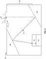
- Fig. 3 is a diagram illustrating a side-view of an example optical device 300 (also referred to as an optical system).
- the example optical device 300 may be configured to collect light to facilitate analysis of the light (e.g., to determine spectral information associated with the light).
- example optical device 300 may include an aperture 310, a diffusive optical element 320, a reflective optical element 330, a reflective optical element 340, an optical filter 350, and/or an optical sensor 360.
- the aperture 310, the diffusive optical element 320, the optical filter 350, and the optical sensor 360 may respectively be the same as, or similar to, the aperture 110, the diffusive optical element 120, the optical filter 150, and the optical sensor 160 described herein in relation to Fig.
- the diffusive optical element 320 may diffuse light received by the aperture 310 to create diffused light
- the optical sensor 360 may be configured to capture spectral information associated with the diffused light that is directed to the input surface of the optical filter 350 by the reflective optical element 330 and/or the reflective optical element 340.
- the reflective optical element 330 may include an optical reflector and/or any other type of optical structure to reflect light.
- the reflective optical element 330 may be positioned within an internal region of the example optical device 300 to receive the diffused light from the diffusive optical element 320 and to reflect the diffused light to the reflective optical element 340.
- the reflective optical element 330 may be configured to reflect one or more first ranges of wavelengths of the diffused light to the reflective optical element 340.
- the reflective optical element 330 may be partially transmissive and/or partially absorbing for wavelengths of the diffused light that are not within the one or more first ranges to prevent the reflective optical element 330 from reflecting diffused light not associated with the one or more first ranges to the reflective optical element 340.
- the reflective optical element 340 may include an optical reflector and/or any other type of optical structure to reflect light.
- the reflective optical element 340 may be positioned within an internal region of the example optical device 300 to receive the diffused light from the reflective optical element 330 (e.g. after the reflective optical element 330 reflects the diffused light) and to reflect the diffused light to the optical filter 350.
- the reflective optical element 340 may be configured to reflect one or more second ranges of wavelengths of the diffused light (e.g., where the one or more second ranges of wavelengths of the diffused light are the same as or different from the one or more first ranges of wavelengths of the diffused light) to the optical filter 350.
- the reflective optical element 340 may be partially transmissive and/or partially absorbing for wavelengths of the diffused light that are not within the one or more second ranges to prevent the reflective optical element 340 from reflecting diffused light not associated with the one or more particular ranges to the optical filter 350.
- light may be diffused by the diffusive optical element 320 to create diffused light, which may enter the example optical device 300 via the aperture 310.
- the reflective optical element 330 and the reflective optical element 340 may direct a light beam of the diffused light to an input surface of the optical filter 350 via a folded optical path 370 that originates at an output surface of the diffusive optical element 320 and terminates at the input surface of the optical filter 350 and that traverses an internal region of the example optical device 300.
- the light beam may transmit from the diffusive optical element 320 to the reflective optical element 330, which may reflect the light beam to the reflective optical element 340, which may reflect the light beam to the input surface of the optical filter 350.
- the folded optical path 370 is long enough to allow the diffused light to disperse while transmitting through the internal region of the example optical device 300.
- This causes the diffused light to be distributed across the input surface of the optical filter 350 (e.g., causes the diffused light to cover at least a particular percentage of the input surface of the optical filter 350, such as 95%, 98%, or 99.5% of the input surface of the optical filter 350), which may allow the optical filter 350 to pass more of the diffused light to the optical sensor 360 than using conventional configurations that do not utilize a folded optical path.
- a length of the folded optical path 370 is greater than a distance 380 between the aperture 310 and an input surface of the optical filter 350, which allows the optical device 300 to have a reduced thickness as compared to using conventional configurations that do not utilize a folded optical path.
- the length of the folded optical path 370 may be approximately 10 mm and the distance 380 may be approximately 3-5 mm. This allows the optical device 300 to be incorporated into user devices, such as mobile phone devices, that require a small form factor (e.g., a thickness on the order of millimeters), which is not otherwise possible.
- the reflective optical element 330 and the reflective optical element 340 may be configured to cause light beams of the diffused light to fall incident on the input surface of the optical filter 350 at angles that satisfy (e.g., that are less than or equal to) an incidence angle threshold.
- This causes the light beams to enter the optical filter 350 such that a channel of the optical filter 350 that receives an individual light beam (e.g., that is associated with a wavelength that the channel is configured to pass) passes the light beam to a corresponding sensor element of the optical sensor 360 (rather than a sensor element that does not correspond to the channel).
- This increases a likelihood that the optical sensor 360 determines accurate spectral information associated with the diffused light as compared to an optical sensor included in an optical device that utilizes a conventional configuration.
- Fig. 3 is provided as an example. Other examples may differ from what is described with regard to Fig. 3 .
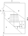
- Fig. 4 is a diagram illustrating a side-view of an example optical device 400 (also referred to as an optical system).
- the example optical device 400 may be configured to collect light to facilitate analysis of the light (e.g., to determine spectral information associated with the light).
- example optical device 400 may include an aperture 410, a diffusive optical element 420, a reflective optical element 430, an optical conduit 440, a reflective optical element 450, an optical filter 460, and/or an optical sensor 470.
- the aperture 410, the diffusive optical element 420, the optical filter 460, and the optical sensor 470 may respectively be the same as, or similar to, the aperture 110, the diffusive optical element 120, the optical filter 150, and the optical sensor 160 described herein in relation to Fig. 1 .
- the diffusive optical element 420 may diffuse light received by the aperture 410 to create diffused light
- the optical sensor 470 may be configured to capture spectral information associated with the diffused light that is directed to the input surface of the optical filter 460 by the reflective optical element 430, the optical conduit 440, and/or the reflective optical element 450.
- the reflective optical element 430 may include an optical reflector and/or any other type of optical structure to reflect light.
- the reflective optical element 430 may be positioned within an internal region of the example optical device 400 to receive the diffused light from the diffusive optical element 420 and to reflect the diffused light to the optical conduit 440.
- the reflective optical element 430 may be configured to reflect one or more first ranges of wavelengths of the diffused light to the optical conduit 440.
- the reflective optical element 430 may be partially transmissive and/or partially absorbing for wavelengths of the diffused light that are not within the one or more first ranges to prevent the reflective optical element 430 from reflecting diffused light not associated with the one or more first ranges to the optical conduit 440.
- the optical conduit 440 may include a light guide, a light pipe, and/or any other type of optical structure to transmit light.
- the optical conduit 440 may be positioned within an internal region of the example optical device 400 to receive the diffused light reflected by the reflective optical element 430 and to transmit the diffused light to the reflective optical element 450.
- the optical conduit 440 may include one or more portions (e.g., one or more interior surfaces, one or more optical structures, and/or the like) that are configured to direct the diffused light to the reflective optical element 450.
- the one or more portions may be configured to reflect, refract, diffract, and/or transmit, among other examples, the diffused light to cause the diffused light to transmit to the reflective optical element 450.
- the optical conduit 440 may include one or more additional portions that are configured to further diffuse the diffused light received from the reflective optical element 430.
- the reflective optical element 450 may include an optical reflector and/or any other type of optical structure to reflect light.
- the reflective optical element 450 may be positioned within an internal region of the example optical device 400 to receive the diffused light from the optical conduit 440 and to reflect the diffused light to the optical filter 460.
- the reflective optical element 450 may be configured to reflect one or more second ranges of wavelengths of the diffused light (e.g., where the one or more second ranges of wavelengths of the diffused light are the same as or different from the one or more first ranges of wavelengths of the diffused light) to the optical filter 460.
- the reflective optical element 450 may be partially transmissive and/or partially absorbing for wavelengths of the diffused light that are not within the one or more second ranges to prevent the reflective optical element 450 from reflecting diffused light not associated with the one or more particular ranges to the optical filter 460.
- light may be diffused by the diffusive optical element 420 to create diffused light, which may enter the example optical device 400 via the aperture 410.
- the reflective optical element 430, the optical conduit 440, and the reflective optical element 450 may direct a light beam of the diffused light to an input surface of the optical filter 460 via a folded optical path 480 that originates at an output surface of the diffusive optical element 420 and terminates at the input surface of the optical filter 460 and that traverses an internal region of the example optical device 400 and an internal region of the optical conduit 440.
- the light beam may transmit from the diffusive optical element 420 to the reflective optical element 430, which may reflect the light beam to the optical conduit 440, which may transmit the light beam to the reflective optical element 450, which may reflect the light beam to the input surface of the optical filter 460.
- the folded optical path 480 is long enough to allow the diffused light to disperse while transmitting through the internal region of the example optical device 400.
- This causes the diffused light to be distributed across the input surface of the optical filter 460 (e.g., causes the diffused light to cover at least a particular percentage of the input surface of the optical filter 460, such as 95%, 98%, or 99.5% of the input surface of the optical filter 460), which may allow the optical filter 460 to pass more of the diffused light to the optical sensor 470 than using conventional configurations that do not utilize a folded optical path.
- a length of the folded optical path 480 is greater than a distance 490 between the aperture 410 and an input surface of the optical filter 460, which allows the optical device 400 to have a reduced thickness as compared to using conventional configurations that do not utilize a folded optical path.
- the length of the folded optical path 480 may be approximately 10 mm and the distance 490 may be approximately 3-5 mm. This allows the optical device 400 to be incorporated into user devices, such as mobile phone devices, that require a small form factor (e.g., a thickness on the order of millimeters), which is not otherwise possible.
- the reflective optical element 430, the optical conduit 440, and the reflective optical element 450 may be configured to cause light beams of the diffused light to fall incident on the input surface of the optical filter 460 at angles that satisfy (e.g., that are less than or equal to) an incidence angle threshold.
- This causes the light beams to enter the optical filter 460 such that a channel of the optical filter 460 that receives an individual light beam (e.g., that is associated with a wavelength that the channel is configured to pass) passes the light beam to a corresponding sensor element of the optical sensor 470 (rather than a sensor element that does not correspond to the channel).
- This increases a likelihood that the optical sensor 470 determines accurate spectral information associated with the diffused light as compared to an optical sensor included in an optical device that utilizes a conventional configuration.
- Fig. 4 is provided as an example. Other examples may differ from what is described with regard to Fig. 4 .
- Fig. 5 is a diagram illustrating a side-view of an example optical device 500 (also referred to as an optical system).
- the example optical device 500 may be configured to collect light to facilitate analysis of the light (e.g., to determine spectral information associated with the light).
- example optical device 500 may include an aperture 510, a diffusive optical element 520, a plurality of optical conduits 530 (shown as optical conduits 530-1 through 530-3), a reflective optical element 540, a reflective optical element 550, an optical filter 560, and/or an optical sensor 570.
- the aperture 510, the diffusive optical element 520, the optical filter 560, and the optical sensor 570 may respectively be the same as, or similar to, the aperture 110, the diffusive optical element 120, the optical filter 150, and the optical sensor 160 described herein in relation to Fig. 1 .
- the diffusive optical element 520 may diffuse light received by the aperture 510 to create diffused light
- the optical sensor 570 may be configured to capture spectral information associated with the diffused light that is directed to the input surface of the optical filter 560 by the plurality of optical conduits 530, the reflective optical element 540, and/or the reflective optical element 550.
- the plurality of optical conduits 530 may each include a light guide, a light pipe, and/or any other type of optical structure to transmit light and may be configured in a similar manner as optical conduit 130 and/or optical conduit 440 described herein.
- the optical conduit 530-1 may be positioned within an internal region of the example optical device 500 (e.g., disposed between the aperture 510 and the reflective optical element 540) to receive the diffused light created by the diffusive optical element 520 and to transmit the diffused light to the reflective optical element 540.
- the optical conduit 530-2 may be positioned within an internal region of the example optical device 500 (e.g., disposed between the reflective optical element 540 and the reflective optical element 550) to receive the diffused light reflected by the reflective optical element 540 and to transmit the diffused light to the reflective optical element 550.
- the optical conduit 530-3 may be positioned within an internal region of the example optical device 500 (e.g., disposed between the reflective optical element 550 and the optical filter 560) to receive the diffused light reflected by the reflective optical element 550 and to transmit the diffused light to the optical filter 560.
- the reflective optical element 540 may include an optical reflector and/or any other type of optical structure to reflect light.
- the reflective optical element 540 may be positioned within an internal region of the example optical device 500 to receive the diffused light from the optical conduit 530-1 and to reflect the diffused light to the optical conduit 530-2.
- the reflective optical element 540 may be configured to reflect one or more first ranges of wavelengths of the diffused light to the optical conduit 530-2.
- the reflective optical element 540 may be partially transmissive and/or partially absorbing for wavelengths of the diffused light that are not within the one or more first ranges to prevent the reflective optical element 540 from reflecting diffused light not associated with the one or more first ranges to the optical conduit 530-2.
- the reflective optical element 550 may include an optical reflector and/or any other type of optical structure to reflect light.
- the reflective optical element 550 may be positioned within an internal region of the example optical device 500 to receive the diffused light from the optical conduit 530-2 and to reflect the diffused light to the optical conduit 530-3.
- the reflective optical element 550 may be configured to reflect one or more second ranges of wavelengths of the diffused light (e.g., where the one or more second ranges of wavelengths of the diffused light are the same as or different from the one or more first ranges of wavelengths of the diffused light) to the optical conduit 530-3.
- the reflective optical element 550 may be partially transmissive and/or partially absorbing for wavelengths of the diffused light that are not within the one or more second ranges to prevent the reflective optical element 550 from reflecting diffused light not associated with the one or more particular ranges to the optical conduit 530-3.
- light may be diffused by the diffusive optical element 520 to create diffused light, which may enter the example optical device 500 via the aperture 510.
- the plurality of optical conduits 530, the reflective optical element 540, and the reflective optical element 550 may direct a light beam of the diffused light to an input surface of the optical filter 560 via a folded optical path 580 that originates at an output surface of the diffusive optical element 520 and terminates at the input surface of the optical filter 560 and that traverses an internal region of the example optical device 500 and respective internal regions of the plurality of optical conduits 530.
- the light beam may transmit from the diffusive optical element 520 to the optical conduit 530-1, which may transmit the light beam to the reflective optical element 540, which may reflect the light beam to the optical conduit 530-2, which may transmit the light beam to the reflective optical element 550, which may reflect the light beam to the optical conduit 530-3, which may transmit the light beam to the input surface of the optical filter 560.
- the folded optical path 580 is long enough to allow the diffused light to disperse while transmitting through the internal region of the example optical device 500 and the respective internal regions of the plurality of optical conduits 530.
- This causes the diffused light to be distributed across the input surface of the optical filter 560 (e.g., causes the diffused light to cover at least a particular percentage of the input surface of the optical filter 560, such as 95%, 98%, or 99.5% of the input surface of the optical filter 560), which may allow the optical filter 560 to pass more of the diffused light to the optical sensor 570 than using conventional configurations that do not utilize a folded optical path.
- a length of the folded optical path 580 is greater than a distance 590 between the aperture 510 and an input surface of the optical filter 560, which allows the optical device 500 to have a reduced thickness as compared to using conventional configurations that do not utilize a folded optical path.
- the length of the folded optical path 580 may be approximately 10 mm and the distance 590 may be approximately 3-5 mm. This allows the optical device 500 to be incorporated into user devices, such as mobile phone devices, that require a small form factor (e.g., a thickness on the order of millimeters), which is not otherwise possible.
- the plurality of optical conduits 530, the reflective optical element 540, and the reflective optical element 550 may be configured to cause light beams of the diffused light to fall incident on the input surface of the optical filter 560 at angles that satisfy (e.g., that are less than or equal to) an incidence angle threshold.
- This causes the light beams to enter the optical filter 560 such that a channel of the optical filter 560 that receives an individual light beam (e.g., that is associated with a wavelength that the channel is configured to pass) passes the light beam to a corresponding sensor element of the optical sensor 570 (rather than a sensor element that does not correspond to the channel).
- This increases a likelihood that the optical sensor 570 determines accurate spectral information associated with the diffused light as compared to an optical sensor included in an optical device that utilizes a conventional configuration.
- Fig. 5 is provided as an example. Other examples may differ from what is described with regard to Fig. 5 .
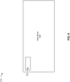
- Fig. 6 is a diagram illustrating an example 600 of a user device 610 that may include an optical device 620.
- User device 610 may include, for example, a communication and/or computing device, such as a mobile phone (e.g., a smart phone, a radiotelephone, and/or the like), a laptop computer, a tablet computer, a handheld computer, a desktop computer, a gaming device, a wearable communication device (e.g., a smart wristwatch, a pair of smart eyeglasses, and/or the like), a spectrometer, or a similar type of device.
- a mobile phone e.g., a smart phone, a radiotelephone, and/or the like
- a laptop computer e.g., a tablet computer, a handheld computer, a desktop computer
- gaming device e.g., a wearable communication device (e.g., a smart wristwatch, a pair of smart eyeglasses, and/or the like), a
- the optical device 620 may include example optical device 100, example optical device 200, example optical device 300, example optical device 400, example optical device 500, or a similar optical device that utilizes a folded optical path.
- the optical device 620 may be included in an optical package of the user device 610. By reducing the size of the optical device 620, the optical device 620 may be implemented in user devices 610, or the optical device 620 may have a smaller footprint in a user device 610 than an optical device associated with a linear optical path.
- Fig. 6 is provided as an example. Other examples may differ from what is described with regard to Fig. 6 .
- the term "component” is intended to be broadly construed as hardware, firmware, or a combination of hardware and software. It will be apparent that systems and/or methods described herein may be implemented in different forms of hardware, firmware, and/or a combination of hardware and software. The actual specialized control hardware or software code used to implement these systems and/or methods is not limiting of the implementations. Thus, the operation and behavior of the systems and/or methods are described herein without reference to specific software code - it being understood that software and hardware can be used to implement the systems and/or methods based on the description herein.
- satisfying a threshold may, depending on the context, refer to a value being greater than the threshold, greater than or equal to the threshold, less than the threshold, less than or equal to the threshold, equal to the threshold, not equal to the threshold, or the like.
- a, b, or c is intended to cover a, b, c, a-b, a-c, b-c, and a-b-c, as well as any combination with multiple of the same item.
- the terms “has,” “have,” “having,” or the like are intended to be open-ended terms. Further, the phrase “based on” is intended to mean “based, at least in part, on” unless explicitly stated otherwise. Also, as used herein, the term “or” is intended to be inclusive when used in a series and may be used interchangeably with “and/or,” unless explicitly stated otherwise (e.g., if used in combination with “either” or “only one of').
Landscapes
- Physics & Mathematics (AREA)
- General Physics & Mathematics (AREA)
- Spectroscopy & Molecular Physics (AREA)
- Optics & Photonics (AREA)
- Photometry And Measurement Of Optical Pulse Characteristics (AREA)
- Spectrometry And Color Measurement (AREA)
- Optical Elements Other Than Lenses (AREA)
- Measurement Of The Respiration, Hearing Ability, Form, And Blood Characteristics Of Living Organisms (AREA)
- Investigating Or Analysing Materials By Optical Means (AREA)
Abstract
Description
- An optical device may be utilized to capture information. For example, the optical device may capture information relating to a set of electromagnetic frequencies. The optical device may include a set of sensor elements (e.g., optical sensors, spectral sensors, and/or image sensors) that capture the information. For example, an array of sensor elements may be utilized to capture information relating to multiple frequencies. The sensor element array may be associated with an optical filter. The optical filter may include one or more channels that respectively pass particular frequencies to sensor elements of the sensor element array.
- In some implementations, an optical device includes an aperture; one or more optical elements; an optical filter; and an optical sensor, wherein: the aperture is configured to receive light; the one or more optical elements are configured to: diffuse the light received by the aperture, direct the diffused light to the optical filter via a folded optical path, wherein a length of the folded optical path is greater than a distance between the aperture and an input surface of the optical filter, and cause the diffused light to be distributed across the input surface of the optical filter; and the optical filter is configured to filter the diffused light distributed across the input surface of the optical filter to pass portions of the diffused light associated with one or more wavelengths to the optical sensor.
- Optionally, the one or more optical elements include at least one of:
- a diffusive optical element;
- a reflective optical element;
- a transmissive optical element;
- a diffractive optical element; or
- a refractive optical element.
- Optionally, the one or more optical elements includes a diffusive optical element, wherein the diffusive optical element is disposed on the aperture, and wherein the diffusive optical element is configured to diffuse the light received by the aperture.
- Optionally, the one or more optical elements includes an optical conduit, wherein: the optical conduit is disposed between the aperture and the optical filter; and the optical conduit is configured to transmit the diffused light to the optical filter via the folded optical path.
- Optionally, the optical conduit includes at least one of: a light pipe; or a light guide.
- Optionally, the optical conduit includes one or more surfaces that are configured to perform at least one of: diffuse the light received by the aperture; or reflect the light received by the aperture.
- Optionally, the one or more optical elements are configured to cause one or more angles of incidence associated with the diffused light, when being distributed across the input surface of the optical filter, to satisfy a threshold to allow a channel of the optical filter to pass a beam of the diffused light that enters the channel to a corresponding sensor element of the optical sensor.
- In some implementations, an optical system includes an aperture; one or more optical elements; an optical filter; and an optical sensor, wherein: the aperture is configured to receive light; and the one or more optical elements are configured to: diffuse the light received by the aperture, cause the diffused light to transmit to the optical filter via a folded optical path and to be distributed across an input surface of the optical filter, wherein a length of the folded optical path is greater than a distance between the aperture and the input surface of the optical filter.
- Optionally, the optical sensor is configured to capture spectral information associated with the diffused light.
- Optionally, the optical filter comprises at least one of:
- a spectral filter;
- a multispectral filter;
- an optical interference filter;
- a bandpass filter;
- a blocking filter;
- a long-wave pass filter;
- a short-wave pass filter;
- a dichroic filter;
- a linear variable filter;
- a circular variable filter;
- a Fabry-Perot filter;
- a Bayer filter;
- a plasmonic filter;
- a photonic crystal filter;
- a nanostructure or metamaterial filter; or
- an absorbent filter.
- Optionally, one or more optical elements comprises a diffusive optical element and an optical conduit, wherein:
- the diffusive optical element is disposed on the aperture;
- a first end of the optical conduit is disposed on the diffusive optical element; and
- a second end of the optical conduit is disposed on the optical filter,
- wherein the folded optical path traverses an internal region of the optical conduit.
- Optionally, the one or more optical elements comprises a diffusive optical element, a reflector, and a prism, wherein:
- the diffusive optical element is configured to diffuse the light received by the aperture;
- the reflector is configured to reflect the diffused light to the prism; and
- the prism is configured to reflect the diffused light within the prism to the input surface of the optical filter,
- wherein the folded optical path originates at an output surface of the diffusive optical element and terminates at the input surface of the optical filter.
- Optionally, the one or more optical elements comprises a diffusive optical element and one or more reflective optical elements,
wherein the folded optical path traverses an internal region of the optical system from an output surface of the diffusive optical element to the input surface of the optical filter via the one or more reflective optical elements. - Optionally, the one or more optical elements comprises a diffusive optical element, a first reflective optical element, a second reflective optical element, and an optical conduit, wherein:
- the diffusive optical element is configured to diffuse the light received by the aperture;
- the first reflective optical element is configured to reflect the diffused light to the optical conduit;
- the optical conduit is configured to direct the diffused light, after the diffused light is reflected by the first reflective optical element, to the second reflective optical element; and
- the second reflective optical element is configured to reflect the diffused light, after the diffused light is directed to the second reflective optical element by the optical conduit, to the input surface of the optical filter.
- Optionally, the one or more optical elements comprises a diffusive optical element, a plurality of optical conduits, and a plurality of reflective optical elements, wherein:
- the diffusive optical element is configured to diffuse the light received by the aperture; and
- the plurality of optical conduits and the plurality of reflective optical elements are configured to reflect the diffused light from the diffusive optical element to the input surface of the optical filter.
- Optionally, the one or more optical elements comprises an optical conduit, wherein:
- one or more first portions of the optical conduit are configured to diffuse the light received by the aperture; and
- one or more second portions of the optical conduit are configured to direct the diffused light to the input surface of the optical filter.
- In some implementations, a user device includes an optical package, comprising: an aperture; one or more optical elements; an optical filter; and an optical sensor, wherein: the one or more optical elements are configured to diffuse light received by the aperture and cause the diffused light to transmit to the optical filter via a folded optical path and to be distributed across an input surface of the optical filter, wherein a length of the folded optical path is greater than a distance between the aperture and the input surface of the optical filter.
- Optionally, the aperture, the one or more optical elements, the optical filter, and the optical sensor are enclosed within the optical package.
- Optionally, the optical filter is a multi-spectral filter and the optical sensor is a multi-spectral sensor.
- Optionally, the one or more optical elements are configured to cause one or more angles of incidence associated with the diffused light, when being distributed across the input surface of the optical filter, to satisfy a threshold to allow a channel of the optical filter to pass a beam of the diffused light that enters the channel to a corresponding sensor element of the optical sensor.
-
-
Fig. 1 is a diagram illustrating a side-view of an example optical device described herein. -
Fig. 2 is a diagram illustrating a side-view of an example optical device described herein. -
Fig. 3 is a diagram illustrating a side-view of an example optical device described herein. -
Fig. 4 is a diagram illustrating a side-view of an example optical device described herein. -
Fig. 5 is a diagram illustrating a side-view of an example optical device described herein. -
Fig. 6 is a diagram illustrating an example of a user device that includes an example optical device described herein. - The following detailed description of example implementations refers to the accompanying drawings. The same reference numbers in different drawings may identify the same or similar elements. The following description uses a spectrometer as an example. However, the techniques, principles, procedures, and methods described herein may be used with any sensor, including but not limited to other optical sensors and spectral sensors.
- An optical device, such as a spectrometer, may be configured to determine spectral information associated with light (e.g., ambient light) captured by the optical device. The light may enter the optical device and may be received by an optical filter and an optical sensor of the optical device (e.g., wherein the optical filter is disposed on the optical sensor). The optical filter may include a set of optical channels designed to respectively pass light in different wavelength ranges to a set of sensors elements of the optical sensor. This allows the optical sensor to determine spectral information associated with the light that relates to the different wavelength ranges.
- Often, the light enters the optical device and falls incident on only a portion of an input surface of the optical filter. Consequently, only optical channels associated with the portion of the input surface of the optical filter pass light (if any) to corresponding optical sensors of the optical sensor. This inhibits the optical sensor's ability to determine accurate spectral information associated with the light.
- In some cases, the optical device may utilize a conventional linear optical path configuration, where the optical device includes an optical diffuser to diffuse the light that enters the optical device. This causes the light to disperse as the light transmits along a linear optical path (e.g., a linear path from an opening of the optical device to the optical filter), which causes the light to distribute across the input surface of the optical filter (and thereby allow distribution of a point spread function of the light across the optical sensor). However, the optical path needs to have a sufficiently long length (e.g., on the order of centimeters) to allow the light to disperse and to fully distribute across the input surface of the optical filter. Consequently, a conventional linear optical path configuration requires an optical device thickness (e.g., on the order of centimeters) that prevents the optical device from being incorporated into user devices, such as mobile phone devices, that require a smaller form factor (e.g., a thickness on the order of millimeters).
- Moreover, the optical diffuser causes some light beams of the light to fall incident on the input surface of the optical filter at extreme angles. This causes the light beams to enter the optical filter such that a channel of the optical filter that receives an individual light beam (e.g., that is associated with a wavelength that the channel is configured to pass) does not pass the light beam to a corresponding sensor element of the optical sensor, but rather, to a different sensor element of the optical sensor. This further inhibits the optical sensor's ability to determine accurate spectral information associated with the light.
- Some implementations described herein provide an optical device that includes an aperture, one or more optical elements, an optical filter, and an optical sensor. The aperture may be configured to receive light (e.g., ambient light). In some implementations, the one or more optical elements may be configured to diffuse the light received by the aperture. For example, a diffusive optical element may diffuse the light. In some implementations, the one or more optical elements may direct the diffused light to the optical filter via a folded optical path (an optical path that changes a heading of a light beam of the diffused light one or more times before the light beam reaches the optical filter). For example, the one or more optical elements may include at least one optical conduit, reflective optical element, transmissive optical element, diffractive optical element, and/or refractive optical element to direct the diffused light to the optical filter via the folded optical path. Accordingly, in some implementations, the one or more elements provide a folded optical path with a sufficiently long length to cause the diffused light to be distributed across an input surface of the optical filter (e.g., to cause the diffused light to cover at least a particular percentage of the input surface of the optical filter, such as 50%, 70%, 95%, 98%, or 99.5% of the optical filter).
- In this way, the optical device increases the optical sensor's ability to determine accurate spectral information associated with light that enters the optical device as opposed to an optical device that does not diffuse light. Further, in some implementations, a length of the folded optical path provided by the one or more optical elements is greater than a distance between the aperture and an input surface of the optical filter, which allows the optical device to have a reduced thickness as compared to an optical device that uses a conventional linear optical path configuration. This allows the optical device to be incorporated into user devices, such as mobile phone devices, that require a small form factor (e.g., a thickness on the order of millimeters), which is not possible for optical devices that use a conventional linear optical path configuration.
- In some implementations, the one or more optical elements of the optical device may be configured to cause light beams of the diffused light to fall incident on the input surface of the optical filter at angles that satisfy (e.g., that are less than or equal to) an incidence angle threshold. This causes the light beams to enter the optical filter such that a channel of the optical filter that receives an individual light beam (e.g., that is associated with a wavelength that the channel is configured to pass) passes the light beam to a corresponding sensor element of the optical sensor. This increases a likelihood that the optical sensor may determine accurate spectral information associated with the diffused light as compared to an optical sensor included in an optical device that utilizes a conventional linear optical path configuration.
-
Fig. 1 is a diagram illustrating a side-view of an example optical device 100 (also referred to as an optical system). The exampleoptical device 100 may be configured to collect light to facilitate analysis of the light (e.g., to determine spectral information associated with the light). As shown inFig. 1 , exampleoptical device 100 may include anaperture 110, a diffusiveoptical element 120, anoptical conduit 130 with a first end 140-1 of theoptical conduit 130 and a second end 140-2 of theoptical conduit 130, anoptical filter 150, and/or anoptical sensor 160. Theaperture 110 may include a lens, a window, or any other type of transmissive optical element that receives light into the exampleoptical device 100. Theaperture 110 may include an aperture stop, or one or more other optical elements, to control an amount of light that enters the exampleoptical device 100 and/or to control a range of incidence angles of the light that enters the exampleoptical device 100 via theaperture 110. - The diffusive
optical element 120 may include an optical diffuser and/or any other type of optical structure to diffuse light. The diffusiveoptical element 120 may be disposed over theaperture 110. For example, as shown inFig. 1 , the diffusiveoptical element 120 may be positioned on an exterior surface of the exampleoptical device 100 to cause light to transmit through the diffusiveoptical element 120 before entering the exampleoptical device 100 via theaperture 110. Other configurations are contemplated. For example, the diffusiveoptical element 120 may be positioned on an interior surface of the exampleoptical device 100 to cause light to enter the exampleoptical device 100 via theaperture 110 and then transmit through the diffusiveoptical element 120. Accordingly, the diffusiveoptical element 120 may diffuse the light received by theaperture 110 to create diffused light. - The
optical conduit 130 may include a light guide, a light pipe, and/or any other type of optical structure to transmit light. In some implementations, theoptical conduit 130 may be configured to receive and to transmit the diffused light created by the diffusiveoptical element 120 to theoptical filter 150. For example, as shown inFig. 1 , theoptical conduit 130 may be disposed between theaperture 110 and theoptical filter 150. The first end 140-1 of theoptical conduit 130 may be disposed on the diffusive optical element 120 (e.g., attached and/or mounted to the diffusiveoptical element 120, close to the diffusiveoptical element 120 to allow the first end 140-1 of theoptical conduit 130 to receive the diffused light, and/or the like). The second end 140-2 of theoptical conduit 130 may be disposed on the optical filter 150 (e.g., attached and/or mounted to theoptical filter 150, close to theoptical filter 150 to allow the second end 140-2 of theoptical conduit 130 to direct the diffused light to theoptical filter 150, and/or the like). In some implementations, when the exampleoptical device 100 does not include the diffusiveoptical element 120, theoptical conduit 130 may be configured to diffuse the light received by theaperture 110 and to transmit the diffused light to theoptical filter 150. - The
optical conduit 130 may include one or more portions (e.g., one or more interior surfaces, one or more optical structures, and/or the like) that are configured to direct the diffused light to theoptical filter 150. For example, the one or more portions may be configured to reflect, refract, diffract, and/or transmit, among other examples, the diffused light to cause the diffused light to transmit to theoptical filter 150. In some implementations, when the exampleoptical device 100 includes the diffusiveoptical element 120, theoptical conduit 130 may include one or more additional portions that are configured to further diffuse the diffused light received from the diffusiveoptical element 120. In some implementations, when the exampleoptical device 100 does not include the diffusiveoptical element 120, the one or more additional portions may be configured to diffuse the light received by theaperture 110. - The
optical filter 150 may include a spectral filter, a multispectral filter, an optical interference filter, a bandpass filter, a blocking filter, a long-wave pass filter, a short-wave pass filter, a dichroic filter, a linear variable filter (LVF), a circular variable filter (CVF), a Fabry-Perot filter (e.g., a Fabry-Perot cavity filter), a Bayer filter, a plasmonic filter, a photonic crystal filter, a nanostructure and/or metamaterial filter, an absorbent filter (e.g., comprising organic dyes, polymers, and/or glasses, among other examples), and/or the like. Theoptical filter 150 may pass one or more wavelengths of the diffused light for sensing by theoptical sensor 160. For example, theoptical filter 150 may comprise one or more channels (also referred to as a filter array), where each channel is configured to pass light associated with a wavelength. In some implementations, theoptical filter 150 may include multiple, different filters that are configured to pass respective spectral ranges to theoptical sensor 160. - The
optical sensor 160 may include a device capable of performing a measurement of light directed toward the optical sensor 160 (e.g., the one or more wavelengths of the diffused light passed by the optical filter 150), such as a spectral sensor or a multi-spectral sensor. Theoptical sensor 160 may be, for example, a silicon (Si) based sensor, an indium-gallium-arsenide (InGaAs) based sensor, a lead-sulfide (PbS) based sensor, or a germanium (Ge) based sensor, may utilize one or more sensor technologies, such as a complementary metal-oxide-semiconductor (CMOS) technology, or a charge-coupled device (CCD) technology, among other examples. In some implementations, theoptical sensor 160 may include multiple sensor elements (e.g., an array of sensor elements, also referred to herein as a sensor array), each configured to obtain information. For example, a sensor element may provide an indication of intensity of light that is incident on the sensor element (e.g., active/inactive or a more granular indication of intensity). In this way, theoptical sensor 160 may be configured to capture spectral information associated with the diffused light that is directed to theoptical filter 150 by theoptical conduit 130. While some implementations described herein are directed to theoptical sensor 160 being configured to capture spectral information, other implementations are also contemplated. For example, theoptical sensor 160 may be configured to capture imaging information, such as hyper-spectral imaging information, multispectral imaging information, and/or the like. - In some implementations, light (e.g., ambient light) may be diffused by the diffusive
optical element 120 to create diffused light, which may enter the exampleoptical device 100 via theaperture 110. The diffused light then may enter the first end 140-1 of theoptical conduit 130. As shown inFig. 1 , theoptical conduit 130 may direct a light beam of the diffused light to theoptical filter 150 via a folded optical path 170 (e.g., an optical path that changes a heading of the light beam one or more or more times before the light beam reaches the optical filter 150). The folded optical path may traverse an internal region of theoptical conduit 130. For example, the foldedoptical path 170 is shown inFig. 1 as traversing the internal region of theoptical conduit 130 from an origination point associated with an output surface of the diffusiveoptical element 120 and/or the first end 140-1 of theoptical conduit 130 to a termination point associated with the second end 140-2 of theoptical conduit 130 and/or the input surface of theoptical filter 150. - In this way, the folded
optical path 170 is long enough to allow the diffused light to disperse while transmitting through theoptical conduit 130. This causes the diffused light to be distributed across the input surface of the optical filter 150 (e.g., causes the diffused light to cover at least a particular percentage of the input surface of theoptical filter 150, such as 95%, 98%, or 99.5% of the input surface of the optical filter 150), which may allow theoptical filter 150 to pass more of the diffused light to theoptical sensor 160 than using conventional configurations that do not utilize a folded optical path. Further, in some implementations, a length of the foldedoptical path 170 is greater than adistance 180 between theaperture 110 and an input surface of theoptical filter 150, which allows theoptical device 100 to have a reduced thickness as compared to using conventional configurations that do not utilize a folded optical path. For example, the length of the foldedoptical path 170 may be approximately 10 mm and thedistance 180 may be approximately 3-5 mm. This allows theoptical device 100 to be incorporated into user devices, such as mobile phone devices, that require a small form factor (e.g., a thickness on the order of millimeters), which is not otherwise possible. - Moreover, the
optical conduit 130 may be configured to cause light beams of the diffused light to fall incident on the input surface of theoptical filter 150 at angles that satisfy (e.g., that are less than or equal to) an incidence angle threshold. This causes the light beams to enter theoptical filter 150 such that a channel of theoptical filter 150 that receives an individual light beam (e.g., that is associated with a wavelength that the channel is configured to pass) passes the light beam to a corresponding sensor element of the optical sensor 160 (rather than a sensor element that does not correspond to the channel). This increases a likelihood that theoptical sensor 160 determines accurate spectral information associated with the diffused light as compared to an optical sensor included in an optical device that utilizes a conventional configuration. - As indicated above,
Fig. 1 is provided as an example. Other examples may differ from what is described with regard toFig. 1 . -
Fig. 2 is a diagram illustrating a side-view of an example optical device 200 (also referred to as an optical system). The exampleoptical device 200 may be configured to collect light to facilitate analysis of the light (e.g., to determine spectral information associated with the light). As shown inFig. 2 , exampleoptical device 200 may include anaperture 210, a diffusiveoptical element 220, a reflectiveoptical element 230, aprism 240, anoptical filter 250, and/or anoptical sensor 260. Theaperture 210, the diffusiveoptical element 220, theoptical filter 250, and theoptical sensor 260 may respectively be the same as, or similar to, theaperture 110, the diffusiveoptical element 120, theoptical filter 150, and theoptical sensor 160 described herein in relation toFig. 1 . Accordingly, the diffusiveoptical element 220 may diffuse light received by theaperture 210 to create diffused light, and theoptical sensor 260 may be configured to capture spectral information associated with the diffused light that is directed to theoptical filter 250 by the reflectiveoptical element 230 and/or theprism 240. - The reflective
optical element 230 may include an optical reflector and/or any other type of optical structure to reflect light. The reflectiveoptical element 230 may be positioned within an internal region of the exampleoptical device 200 to receive the diffused light from the diffusiveoptical element 220 and to reflect the diffused light to theprism 240. In some implementations, the reflectiveoptical element 230 may be configured to reflect one or more particular ranges of wavelengths of the diffused light to theprism 240. For example, the reflectiveoptical element 230 may be partially transmissive and/or partially absorbing for wavelengths of the diffused light that are not within the one or more particular ranges to prevent the reflectiveoptical element 230 from reflecting diffused light not associated with the one or more particular ranges to theprism 240. Theprism 240 may include an imaging prism, such as a pentaprism, and/or any other type of optical structure to, for example, reflect, refract, polarize, and/or deflect light. Theprism 240 may be positioned within the internal region of the exampleoptical device 200 to receive the diffused light from the reflective optical element 230 (e.g. after the reflectiveoptical element 230 reflects the diffused light) and to direct the diffused light to theoptical filter 250. - In some implementations, light (e.g., ambient light) may be diffused by the diffusive
optical element 220 to create diffused light, which may enter the exampleoptical device 200 via theaperture 210. As shown inFig. 2 , the reflectiveoptical element 230 and theprism 240 may direct a light beam of the diffused light to an input surface of theoptical filter 250 via a foldedoptical path 270 that originates at an output surface of the diffusiveoptical element 220 and terminates at the input surface of theoptical filter 250 and that traverses an internal region of the exampleoptical device 200. For example, the light beam may transmit from the output surface of the diffusiveoptical element 220 to the reflectiveoptical element 230, which may reflect the light beam to theprism 240. Theprism 240 may internally reflect the light beam one or more times (e.g., two times as shown inFig. 2 ) to cause the light beam to transmit to the input surface of theoptical filter 250. - In this way, the folded
optical path 270 is long enough to allow the diffused light to disperse while transmitting through the internal region of the exampleoptical device 200. This causes the diffused light to be distributed across the input surface of the optical filter 250 (e.g., causes the diffused light to cover at least a particular percentage of the input surface of theoptical filter 250, such as 95%, 98%, or 99.5% of the input surface of the optical filter 250), which may allow theoptical filter 250 to pass more of the diffused light to theoptical sensor 260 than using conventional configurations that do not utilize a folded optical path. Further, in some implementations, a length of the foldedoptical path 270 is greater than adistance 280 between theaperture 210 and an input surface of theoptical filter 250, which allows theoptical device 200 to have a reduced thickness as compared to using conventional configurations that do not utilize a folded optical path. For example, the length of the foldedoptical path 270 may be approximately 10 mm and thedistance 280 may be approximately 3-5 mm. This allows theoptical device 200 to be incorporated into user devices, such as mobile phone devices, that require a small form factor (e.g., a thickness on the order of millimeters), which is not otherwise possible. - Moreover, the reflective
optical element 230 and theprism 240 may be configured to cause light beams of the diffused light to fall incident on the input surface of theoptical filter 250 at angles that satisfy (e.g., that are less than or equal to) an incidence angle threshold. This causes the light beams to enter theoptical filter 250 such that a channel of theoptical filter 250 that receives an individual light beam (e.g., that is associated with a wavelength that the channel is configured to pass) passes the light beam to a corresponding sensor element of the optical sensor 260 (rather than a sensor element that does not correspond to the channel). This increases a likelihood that theoptical sensor 260 determines accurate spectral information associated with the diffused light as compared to an optical sensor included in an optical device that utilizes a conventional configuration. - As indicated above,
Fig. 2 is provided as an example. Other examples may differ from what is described with regard toFig. 2 . -
Fig. 3 is a diagram illustrating a side-view of an example optical device 300 (also referred to as an optical system). The exampleoptical device 300 may be configured to collect light to facilitate analysis of the light (e.g., to determine spectral information associated with the light). As shown inFig. 3 , exampleoptical device 300 may include anaperture 310, a diffusiveoptical element 320, a reflectiveoptical element 330, a reflectiveoptical element 340, anoptical filter 350, and/or anoptical sensor 360. Theaperture 310, the diffusiveoptical element 320, theoptical filter 350, and theoptical sensor 360 may respectively be the same as, or similar to, theaperture 110, the diffusiveoptical element 120, theoptical filter 150, and theoptical sensor 160 described herein in relation toFig. 1 . Accordingly, the diffusiveoptical element 320 may diffuse light received by theaperture 310 to create diffused light, and theoptical sensor 360 may be configured to capture spectral information associated with the diffused light that is directed to the input surface of theoptical filter 350 by the reflectiveoptical element 330 and/or the reflectiveoptical element 340. - The reflective
optical element 330 may include an optical reflector and/or any other type of optical structure to reflect light. The reflectiveoptical element 330 may be positioned within an internal region of the exampleoptical device 300 to receive the diffused light from the diffusiveoptical element 320 and to reflect the diffused light to the reflectiveoptical element 340. In some implementations, the reflectiveoptical element 330 may be configured to reflect one or more first ranges of wavelengths of the diffused light to the reflectiveoptical element 340. For example, the reflectiveoptical element 330 may be partially transmissive and/or partially absorbing for wavelengths of the diffused light that are not within the one or more first ranges to prevent the reflectiveoptical element 330 from reflecting diffused light not associated with the one or more first ranges to the reflectiveoptical element 340. - The reflective
optical element 340 may include an optical reflector and/or any other type of optical structure to reflect light. The reflectiveoptical element 340 may be positioned within an internal region of the exampleoptical device 300 to receive the diffused light from the reflective optical element 330 (e.g. after the reflectiveoptical element 330 reflects the diffused light) and to reflect the diffused light to theoptical filter 350. In some implementations, the reflectiveoptical element 340 may be configured to reflect one or more second ranges of wavelengths of the diffused light (e.g., where the one or more second ranges of wavelengths of the diffused light are the same as or different from the one or more first ranges of wavelengths of the diffused light) to theoptical filter 350. For example, the reflectiveoptical element 340 may be partially transmissive and/or partially absorbing for wavelengths of the diffused light that are not within the one or more second ranges to prevent the reflectiveoptical element 340 from reflecting diffused light not associated with the one or more particular ranges to theoptical filter 350. - In some implementations, light (e.g., ambient light) may be diffused by the diffusive
optical element 320 to create diffused light, which may enter the exampleoptical device 300 via theaperture 310. As shown inFig. 3 , the reflectiveoptical element 330 and the reflectiveoptical element 340 may direct a light beam of the diffused light to an input surface of theoptical filter 350 via a foldedoptical path 370 that originates at an output surface of the diffusiveoptical element 320 and terminates at the input surface of theoptical filter 350 and that traverses an internal region of the exampleoptical device 300. For example, the light beam may transmit from the diffusiveoptical element 320 to the reflectiveoptical element 330, which may reflect the light beam to the reflectiveoptical element 340, which may reflect the light beam to the input surface of theoptical filter 350. - In this way, the folded
optical path 370 is long enough to allow the diffused light to disperse while transmitting through the internal region of the exampleoptical device 300. This causes the diffused light to be distributed across the input surface of the optical filter 350 (e.g., causes the diffused light to cover at least a particular percentage of the input surface of theoptical filter 350, such as 95%, 98%, or 99.5% of the input surface of the optical filter 350), which may allow theoptical filter 350 to pass more of the diffused light to theoptical sensor 360 than using conventional configurations that do not utilize a folded optical path. Further, in some implementations, a length of the foldedoptical path 370 is greater than adistance 380 between theaperture 310 and an input surface of theoptical filter 350, which allows theoptical device 300 to have a reduced thickness as compared to using conventional configurations that do not utilize a folded optical path. For example, the length of the foldedoptical path 370 may be approximately 10 mm and thedistance 380 may be approximately 3-5 mm. This allows theoptical device 300 to be incorporated into user devices, such as mobile phone devices, that require a small form factor (e.g., a thickness on the order of millimeters), which is not otherwise possible. - Moreover, the reflective
optical element 330 and the reflectiveoptical element 340 may be configured to cause light beams of the diffused light to fall incident on the input surface of theoptical filter 350 at angles that satisfy (e.g., that are less than or equal to) an incidence angle threshold. This causes the light beams to enter theoptical filter 350 such that a channel of theoptical filter 350 that receives an individual light beam (e.g., that is associated with a wavelength that the channel is configured to pass) passes the light beam to a corresponding sensor element of the optical sensor 360 (rather than a sensor element that does not correspond to the channel). This increases a likelihood that theoptical sensor 360 determines accurate spectral information associated with the diffused light as compared to an optical sensor included in an optical device that utilizes a conventional configuration. - As indicated above,
Fig. 3 is provided as an example. Other examples may differ from what is described with regard toFig. 3 . -
Fig. 4 is a diagram illustrating a side-view of an example optical device 400 (also referred to as an optical system). The exampleoptical device 400 may be configured to collect light to facilitate analysis of the light (e.g., to determine spectral information associated with the light). As shown inFig. 4 , exampleoptical device 400 may include anaperture 410, a diffusiveoptical element 420, a reflectiveoptical element 430, anoptical conduit 440, a reflectiveoptical element 450, anoptical filter 460, and/or anoptical sensor 470. Theaperture 410, the diffusiveoptical element 420, theoptical filter 460, and theoptical sensor 470 may respectively be the same as, or similar to, theaperture 110, the diffusiveoptical element 120, theoptical filter 150, and theoptical sensor 160 described herein in relation toFig. 1 . Accordingly, the diffusiveoptical element 420 may diffuse light received by theaperture 410 to create diffused light, and theoptical sensor 470 may be configured to capture spectral information associated with the diffused light that is directed to the input surface of theoptical filter 460 by the reflectiveoptical element 430, theoptical conduit 440, and/or the reflectiveoptical element 450. - The reflective
optical element 430 may include an optical reflector and/or any other type of optical structure to reflect light. The reflectiveoptical element 430 may be positioned within an internal region of the exampleoptical device 400 to receive the diffused light from the diffusiveoptical element 420 and to reflect the diffused light to theoptical conduit 440. In some implementations, the reflectiveoptical element 430 may be configured to reflect one or more first ranges of wavelengths of the diffused light to theoptical conduit 440. For example, the reflectiveoptical element 430 may be partially transmissive and/or partially absorbing for wavelengths of the diffused light that are not within the one or more first ranges to prevent the reflectiveoptical element 430 from reflecting diffused light not associated with the one or more first ranges to theoptical conduit 440. - The
optical conduit 440 may include a light guide, a light pipe, and/or any other type of optical structure to transmit light. In some implementations, theoptical conduit 440 may be positioned within an internal region of the exampleoptical device 400 to receive the diffused light reflected by the reflectiveoptical element 430 and to transmit the diffused light to the reflectiveoptical element 450. Theoptical conduit 440 may include one or more portions (e.g., one or more interior surfaces, one or more optical structures, and/or the like) that are configured to direct the diffused light to the reflectiveoptical element 450. For example, the one or more portions may be configured to reflect, refract, diffract, and/or transmit, among other examples, the diffused light to cause the diffused light to transmit to the reflectiveoptical element 450. In some implementations, theoptical conduit 440 may include one or more additional portions that are configured to further diffuse the diffused light received from the reflectiveoptical element 430. - The reflective
optical element 450 may include an optical reflector and/or any other type of optical structure to reflect light. The reflectiveoptical element 450 may be positioned within an internal region of the exampleoptical device 400 to receive the diffused light from theoptical conduit 440 and to reflect the diffused light to theoptical filter 460. In some implementations, the reflectiveoptical element 450 may be configured to reflect one or more second ranges of wavelengths of the diffused light (e.g., where the one or more second ranges of wavelengths of the diffused light are the same as or different from the one or more first ranges of wavelengths of the diffused light) to theoptical filter 460. For example, the reflectiveoptical element 450 may be partially transmissive and/or partially absorbing for wavelengths of the diffused light that are not within the one or more second ranges to prevent the reflectiveoptical element 450 from reflecting diffused light not associated with the one or more particular ranges to theoptical filter 460. - In some implementations, light (e.g., ambient light) may be diffused by the diffusive
optical element 420 to create diffused light, which may enter the exampleoptical device 400 via theaperture 410. As shown inFig. 4 , the reflectiveoptical element 430, theoptical conduit 440, and the reflectiveoptical element 450 may direct a light beam of the diffused light to an input surface of theoptical filter 460 via a foldedoptical path 480 that originates at an output surface of the diffusiveoptical element 420 and terminates at the input surface of theoptical filter 460 and that traverses an internal region of the exampleoptical device 400 and an internal region of theoptical conduit 440. For example, the light beam may transmit from the diffusiveoptical element 420 to the reflectiveoptical element 430, which may reflect the light beam to theoptical conduit 440, which may transmit the light beam to the reflectiveoptical element 450, which may reflect the light beam to the input surface of theoptical filter 460. - In this way, the folded
optical path 480 is long enough to allow the diffused light to disperse while transmitting through the internal region of the exampleoptical device 400. This causes the diffused light to be distributed across the input surface of the optical filter 460 (e.g., causes the diffused light to cover at least a particular percentage of the input surface of theoptical filter 460, such as 95%, 98%, or 99.5% of the input surface of the optical filter 460), which may allow theoptical filter 460 to pass more of the diffused light to theoptical sensor 470 than using conventional configurations that do not utilize a folded optical path. Further, in some implementations, a length of the foldedoptical path 480 is greater than adistance 490 between theaperture 410 and an input surface of theoptical filter 460, which allows theoptical device 400 to have a reduced thickness as compared to using conventional configurations that do not utilize a folded optical path. For example, the length of the foldedoptical path 480 may be approximately 10 mm and thedistance 490 may be approximately 3-5 mm. This allows theoptical device 400 to be incorporated into user devices, such as mobile phone devices, that require a small form factor (e.g., a thickness on the order of millimeters), which is not otherwise possible. - Moreover, the reflective
optical element 430, theoptical conduit 440, and the reflectiveoptical element 450 may be configured to cause light beams of the diffused light to fall incident on the input surface of theoptical filter 460 at angles that satisfy (e.g., that are less than or equal to) an incidence angle threshold. This causes the light beams to enter theoptical filter 460 such that a channel of theoptical filter 460 that receives an individual light beam (e.g., that is associated with a wavelength that the channel is configured to pass) passes the light beam to a corresponding sensor element of the optical sensor 470 (rather than a sensor element that does not correspond to the channel). This increases a likelihood that theoptical sensor 470 determines accurate spectral information associated with the diffused light as compared to an optical sensor included in an optical device that utilizes a conventional configuration. - As indicated above,
Fig. 4 is provided as an example. Other examples may differ from what is described with regard toFig. 4 . -
Fig. 5 is a diagram illustrating a side-view of an example optical device 500 (also referred to as an optical system). The exampleoptical device 500 may be configured to collect light to facilitate analysis of the light (e.g., to determine spectral information associated with the light). As shown inFig. 5 , exampleoptical device 500 may include anaperture 510, a diffusiveoptical element 520, a plurality of optical conduits 530 (shown as optical conduits 530-1 through 530-3), a reflectiveoptical element 540, a reflectiveoptical element 550, anoptical filter 560, and/or anoptical sensor 570. Theaperture 510, the diffusiveoptical element 520, theoptical filter 560, and theoptical sensor 570 may respectively be the same as, or similar to, theaperture 110, the diffusiveoptical element 120, theoptical filter 150, and theoptical sensor 160 described herein in relation toFig. 1 . Accordingly, the diffusiveoptical element 520 may diffuse light received by theaperture 510 to create diffused light, and theoptical sensor 570 may be configured to capture spectral information associated with the diffused light that is directed to the input surface of theoptical filter 560 by the plurality of optical conduits 530, the reflectiveoptical element 540, and/or the reflectiveoptical element 550. - The plurality of optical conduits 530 may each include a light guide, a light pipe, and/or any other type of optical structure to transmit light and may be configured in a similar manner as
optical conduit 130 and/oroptical conduit 440 described herein. In some implementations, the optical conduit 530-1 may be positioned within an internal region of the example optical device 500 (e.g., disposed between theaperture 510 and the reflective optical element 540) to receive the diffused light created by the diffusiveoptical element 520 and to transmit the diffused light to the reflectiveoptical element 540. The optical conduit 530-2 may be positioned within an internal region of the example optical device 500 (e.g., disposed between the reflectiveoptical element 540 and the reflective optical element 550) to receive the diffused light reflected by the reflectiveoptical element 540 and to transmit the diffused light to the reflectiveoptical element 550. The optical conduit 530-3 may be positioned within an internal region of the example optical device 500 (e.g., disposed between the reflectiveoptical element 550 and the optical filter 560) to receive the diffused light reflected by the reflectiveoptical element 550 and to transmit the diffused light to theoptical filter 560. - The reflective
optical element 540 may include an optical reflector and/or any other type of optical structure to reflect light. The reflectiveoptical element 540 may be positioned within an internal region of the exampleoptical device 500 to receive the diffused light from the optical conduit 530-1 and to reflect the diffused light to the optical conduit 530-2. In some implementations, the reflectiveoptical element 540 may be configured to reflect one or more first ranges of wavelengths of the diffused light to the optical conduit 530-2. For example, the reflectiveoptical element 540 may be partially transmissive and/or partially absorbing for wavelengths of the diffused light that are not within the one or more first ranges to prevent the reflectiveoptical element 540 from reflecting diffused light not associated with the one or more first ranges to the optical conduit 530-2. - The reflective
optical element 550 may include an optical reflector and/or any other type of optical structure to reflect light. The reflectiveoptical element 550 may be positioned within an internal region of the exampleoptical device 500 to receive the diffused light from the optical conduit 530-2 and to reflect the diffused light to the optical conduit 530-3. In some implementations, the reflectiveoptical element 550 may be configured to reflect one or more second ranges of wavelengths of the diffused light (e.g., where the one or more second ranges of wavelengths of the diffused light are the same as or different from the one or more first ranges of wavelengths of the diffused light) to the optical conduit 530-3. For example, the reflectiveoptical element 550 may be partially transmissive and/or partially absorbing for wavelengths of the diffused light that are not within the one or more second ranges to prevent the reflectiveoptical element 550 from reflecting diffused light not associated with the one or more particular ranges to the optical conduit 530-3. - In some implementations, light (e.g., ambient light) may be diffused by the diffusive
optical element 520 to create diffused light, which may enter the exampleoptical device 500 via theaperture 510. As shown inFig. 5 , the plurality of optical conduits 530, the reflectiveoptical element 540, and the reflectiveoptical element 550 may direct a light beam of the diffused light to an input surface of theoptical filter 560 via a foldedoptical path 580 that originates at an output surface of the diffusiveoptical element 520 and terminates at the input surface of theoptical filter 560 and that traverses an internal region of the exampleoptical device 500 and respective internal regions of the plurality of optical conduits 530. For example, the light beam may transmit from the diffusiveoptical element 520 to the optical conduit 530-1, which may transmit the light beam to the reflectiveoptical element 540, which may reflect the light beam to the optical conduit 530-2, which may transmit the light beam to the reflectiveoptical element 550, which may reflect the light beam to the optical conduit 530-3, which may transmit the light beam to the input surface of theoptical filter 560. - In this way, the folded
optical path 580 is long enough to allow the diffused light to disperse while transmitting through the internal region of the exampleoptical device 500 and the respective internal regions of the plurality of optical conduits 530. This causes the diffused light to be distributed across the input surface of the optical filter 560 (e.g., causes the diffused light to cover at least a particular percentage of the input surface of theoptical filter 560, such as 95%, 98%, or 99.5% of the input surface of the optical filter 560), which may allow theoptical filter 560 to pass more of the diffused light to theoptical sensor 570 than using conventional configurations that do not utilize a folded optical path. Further, in some implementations, a length of the foldedoptical path 580 is greater than adistance 590 between theaperture 510 and an input surface of theoptical filter 560, which allows theoptical device 500 to have a reduced thickness as compared to using conventional configurations that do not utilize a folded optical path. For example, the length of the foldedoptical path 580 may be approximately 10 mm and thedistance 590 may be approximately 3-5 mm. This allows theoptical device 500 to be incorporated into user devices, such as mobile phone devices, that require a small form factor (e.g., a thickness on the order of millimeters), which is not otherwise possible. - Moreover, the plurality of optical conduits 530, the reflective
optical element 540, and the reflectiveoptical element 550 may be configured to cause light beams of the diffused light to fall incident on the input surface of theoptical filter 560 at angles that satisfy (e.g., that are less than or equal to) an incidence angle threshold. This causes the light beams to enter theoptical filter 560 such that a channel of theoptical filter 560 that receives an individual light beam (e.g., that is associated with a wavelength that the channel is configured to pass) passes the light beam to a corresponding sensor element of the optical sensor 570 (rather than a sensor element that does not correspond to the channel). This increases a likelihood that theoptical sensor 570 determines accurate spectral information associated with the diffused light as compared to an optical sensor included in an optical device that utilizes a conventional configuration. - As indicated above,
Fig. 5 is provided as an example. Other examples may differ from what is described with regard toFig. 5 . -
Fig. 6 is a diagram illustrating an example 600 of a user device 610 that may include anoptical device 620. User device 610 may include, for example, a communication and/or computing device, such as a mobile phone (e.g., a smart phone, a radiotelephone, and/or the like), a laptop computer, a tablet computer, a handheld computer, a desktop computer, a gaming device, a wearable communication device (e.g., a smart wristwatch, a pair of smart eyeglasses, and/or the like), a spectrometer, or a similar type of device. Theoptical device 620 may include exampleoptical device 100, exampleoptical device 200, exampleoptical device 300, exampleoptical device 400, exampleoptical device 500, or a similar optical device that utilizes a folded optical path. Theoptical device 620 may be included in an optical package of the user device 610. By reducing the size of theoptical device 620, theoptical device 620 may be implemented in user devices 610, or theoptical device 620 may have a smaller footprint in a user device 610 than an optical device associated with a linear optical path. - As indicated above,
Fig. 6 is provided as an example. Other examples may differ from what is described with regard toFig. 6 . - The foregoing disclosure provides illustration and description, but is not intended to be exhaustive or to limit the implementations to the precise forms disclosed. Modifications and variations may be made in light of the above disclosure or may be acquired from practice of the implementations.
- As used herein, the term "component" is intended to be broadly construed as hardware, firmware, or a combination of hardware and software. It will be apparent that systems and/or methods described herein may be implemented in different forms of hardware, firmware, and/or a combination of hardware and software. The actual specialized control hardware or software code used to implement these systems and/or methods is not limiting of the implementations. Thus, the operation and behavior of the systems and/or methods are described herein without reference to specific software code - it being understood that software and hardware can be used to implement the systems and/or methods based on the description herein.
- As used herein, satisfying a threshold may, depending on the context, refer to a value being greater than the threshold, greater than or equal to the threshold, less than the threshold, less than or equal to the threshold, equal to the threshold, not equal to the threshold, or the like.
- Even though particular combinations of features are recited in the claims and/or disclosed in the specification, these combinations are not intended to limit the disclosure of various implementations. In fact, many of these features may be combined in ways not specifically recited in the claims and/or disclosed in the specification. Although each dependent claim listed below may directly depend on only one claim, the disclosure of various implementations includes each dependent claim in combination with every other claim in the claim set. As used herein, a phrase referring to "at least one of' a list of items refers to any combination of those items, including single members. As an example, "at least one of: a, b, or c" is intended to cover a, b, c, a-b, a-c, b-c, and a-b-c, as well as any combination with multiple of the same item.
- No element, act, or instruction used herein should be construed as critical or essential unless explicitly described as such. Also, as used herein, the articles "a" and "an" are intended to include one or more items, and may be used interchangeably with "one or more." Further, as used herein, the article "the" is intended to include one or more items referenced in connection with the article "the" and may be used interchangeably with "the one or more." Furthermore, as used herein, the term "set" is intended to include one or more items (e.g., related items, unrelated items, or a combination of related and unrelated items), and may be used interchangeably with "one or more." Where only one item is intended, the phrase "only one" or similar language is used. Also, as used herein, the terms "has," "have," "having," or the like are intended to be open-ended terms. Further, the phrase "based on" is intended to mean "based, at least in part, on" unless explicitly stated otherwise. Also, as used herein, the term "or" is intended to be inclusive when used in a series and may be used interchangeably with "and/or," unless explicitly stated otherwise (e.g., if used in combination with "either" or "only one of').
Claims (15)
- An optical device, comprising:an aperture;one or more optical elements;an optical filter; andan optical sensor, wherein:the aperture is configured to receive light;the one or more optical elements are configured to:diffuse the light received by the aperture,direct the diffused light to the optical filter via a folded optical path, wherein a length of the folded optical path is greater than a distance between the aperture and an input surface of the optical filter,and
cause the diffused light to be distributed across the input surface of the optical filter; andthe optical filter is configured to filter the diffused light distributed across the input surface of the optical filter to pass portions of the diffused light associated with one or more wavelengths to the optical sensor. - The optical device of claim 1, wherein the one or more optical elements include at least one of:a diffusive optical element;a reflective optical element;a transmissive optical element;a diffractive optical element; ora refractive optical element.
- The optical device of claim 1 or claim 2, wherein either(i) the one or more optical elements includes a diffusive optical element,wherein the diffusive optical element is disposed on the aperture, andwherein the diffusive optical element is configured to diffuse the light received by the aperture; or.(ii) the one or more optical elements includes an optical conduit, wherein:the optical conduit is disposed between the aperture and the optical filter; andthe optical conduit is configured to transmit the diffused light to the optical filter via the folded optical path; or(iii) a combination of same.
- The optical device of any one of the preceding claims, wherein the optical conduit includes at least one of:a light pipe; ora light guide.
- The optical device of any one of the preceding claims, wherein the optical conduit includes one or more surfaces that are configured to perform at least one of:diffuse the light received by the aperture; orreflect the light received by the aperture.
- The optical device of any one of the preceding claims, wherein the one or more optical elements are configured to cause one or more angles of incidence associated with the diffused light, when being distributed across the input surface of the optical filter, to satisfy a threshold to allow a channel of the optical filter to pass a beam of the diffused light that enters the channel to a corresponding sensor element of the optical sensor.
- An optical system, comprising:an aperture;one or more optical elements;an optical filter; andan optical sensor, wherein:the aperture is configured to receive light; andthe one or more optical elements are configured to:diffuse the light received by the aperture,cause the diffused light to transmit to the optical filter via a folded optical path and to be distributed across an input surface of the optical filter,
wherein a length of the folded optical path is greater than a distance between the aperture and the input surface of the optical filter. - The optical system of claim 7, wherein the optical sensor is configured to capture spectral information associated with the diffused light.
- The optical system of claim 7 or claim 8, wherein the optical filter comprises at least one of:a spectral filter;a multispectral filter;an optical interference filter;a bandpass filter;a blocking filter;a long-wave pass filter;a short-wave pass filter;a dichroic filter;a linear variable filter;a circular variable filter;a Fabry-Perot filter;a Bayer filter;a plasmonic filter;a photonic crystal filter;a nanostructure or metamaterial filter; oran absorbent filter.
- The optical system of any one of claims 7 to 9, wherein either(i) the one or more optical elements comprises a diffusive optical element and an optical conduit, wherein:the diffusive optical element is disposed on the aperture;a first end of the optical conduit is disposed on the diffusive optical element; anda second end of the optical conduit is disposed on the optical filter,
wherein the folded optical path traverses an internal region of the optical conduit; or(ii) the one or more optical elements comprises a diffusive optical element, a reflector, and a prism, wherein:the diffusive optical element is configured to diffuse the light received by the aperture;the reflector is configured to reflect the diffused light to the prism; andthe prism is configured to reflect the diffused light within the prism to the input surface of the optical filter,
wherein the folded optical path originates at an output surface of the diffusive optical element and terminates at the input surface of the optical filter; or.(iii) the one or more optical elements comprises a diffusive optical element and one or more reflective optical elements,
wherein the folded optical path traverses an internal region of the optical system from an output surface of the diffusive optical element to the input surface of the optical filter via the one or more reflective optical elements; or.(iv) the one or more optical elements comprises a diffusive optical element, a first reflective optical element, a second reflective optical element, and an optical conduit, wherein:the diffusive optical element is configured to diffuse the light received by the aperture;the first reflective optical element is configured to reflect the diffused light to the optical conduit;the optical conduit is configured to direct the diffused light, after the diffused light is reflected by the first reflective optical element, to the second reflective optical element; andthe second reflective optical element is configured to reflect the diffused light, after the diffused light is directed to the second reflective optical element by the optical conduit, to the input surface of the optical filter; or(v) the one or more optical elements comprises a diffusive optical element, a plurality of optical conduits, and a plurality of reflective optical elements, wherein:the diffusive optical element is configured to diffuse the light received by the aperture; andthe plurality of optical conduits and the plurality of reflective optical elements are configured to reflect the diffused light from the diffusive optical element to the input surface of the optical filter. - The optical system of any one of claims 7 to 10, wherein the one or more optical elements comprises an optical conduit, wherein:one or more first portions of the optical conduit are configured to diffuse the light received by the aperture; andone or more second portions of the optical conduit are configured to direct the diffused light to the input surface of the optical filter.
- A user device comprising:an optical package, comprising:an aperture;one or more optical elements;an optical filter; andan optical sensor, wherein:the one or more optical elements are configured to diffuse light received by the aperture and cause the diffused light to transmit to the optical filter via a folded optical path and to be distributed across an input surface of the optical filter,
wherein a length of the folded optical path is greater than a distance between the aperture and the input surface of the optical filter. - The user device of claim 12, wherein the aperture, the one or more optical elements, the optical filter, and the optical sensor are enclosed within the optical package.
- The user device of claim 12 or claim 13, wherein the optical filter is a multi-spectral filter and the optical sensor is a multi-spectral sensor.
- The user device of any one of claims 12 to 14, wherein the one or more optical elements are configured to cause one or more angles of incidence associated with the diffused light, when being distributed across the input surface of the optical filter, to satisfy a threshold to allow a channel of the optical filter to pass a beam of the diffused light that enters the channel to a corresponding sensor element of the optical sensor.
Applications Claiming Priority (1)
| Application Number | Priority Date | Filing Date | Title |
|---|---|---|---|
| US17/123,691 US11740131B2 (en) | 2020-12-16 | 2020-12-16 | Optical device with a folded optical path |
Publications (1)
| Publication Number | Publication Date |
|---|---|
| EP4016160A1 true EP4016160A1 (en) | 2022-06-22 |
Family
ID=78592376
Family Applications (1)
| Application Number | Title | Priority Date | Filing Date |
|---|---|---|---|
| EP21199557.6A Pending EP4016160A1 (en) | 2020-12-16 | 2021-09-28 | Optical device with a folded optical path |
Country Status (4)
| Country | Link |
|---|---|
| US (3) | US11740131B2 (en) |
| EP (1) | EP4016160A1 (en) |
| KR (2) | KR102840078B1 (en) |
| CN (1) | CN114636433A (en) |
Families Citing this family (2)
| Publication number | Priority date | Publication date | Assignee | Title |
|---|---|---|---|---|
| US11740131B2 (en) | 2020-12-16 | 2023-08-29 | Viavi Solutions Inc. | Optical device with a folded optical path |
| EP4587812A1 (en) * | 2022-09-15 | 2025-07-23 | trinamiX GmbH | Spectrometer device and system for detecting incident radiation generated by an object |
Citations (5)
| Publication number | Priority date | Publication date | Assignee | Title |
|---|---|---|---|---|
| US9316539B1 (en) * | 2015-03-10 | 2016-04-19 | LightHaus Photonics Pte. Ltd. | Compact spectrometer |
| US20170184453A1 (en) * | 2015-12-29 | 2017-06-29 | Oak Analytics | Compact spectrometer |
| WO2017197013A1 (en) * | 2016-05-10 | 2017-11-16 | Chromation Inc. | Integration of optical components within a folded optical path |
| US20190186991A1 (en) * | 2017-12-15 | 2019-06-20 | Horiba Instruments Incorporated | Compact spectroscopic optical instrument |
| DE102018203840A1 (en) * | 2018-03-14 | 2019-09-19 | Robert Bosch Gmbh | Fourier transform spectrometer, method of making a Fourier transform spectrometer and method of displaying an electromagnetic spectrum |
Family Cites Families (5)
| Publication number | Priority date | Publication date | Assignee | Title |
|---|---|---|---|---|
| DE102018205401B4 (en) * | 2018-04-10 | 2022-06-15 | Fraunhofer-Gesellschaft zur Förderung der angewandten Forschung e.V. | Spectral analysis system for recording a spectrum |
| CN109256294B (en) * | 2018-09-27 | 2020-05-15 | 温州长江汽车电子有限公司 | A car knob switch |
| CN113767315B (en) * | 2019-01-18 | 2024-05-24 | 上海宜晟生物科技有限公司 | Multi-mode lighting system |
| EP3948186A4 (en) * | 2019-03-25 | 2022-12-28 | MKS Technology (d/b/a Snowy Range Instruments) | MULTIPLE DISPERSION SPECTROMETER |
| US11740131B2 (en) | 2020-12-16 | 2023-08-29 | Viavi Solutions Inc. | Optical device with a folded optical path |
-
2020
- 2020-12-16 US US17/123,691 patent/US11740131B2/en active Active
-
2021
- 2021-09-28 EP EP21199557.6A patent/EP4016160A1/en active Pending
- 2021-10-19 CN CN202111216886.XA patent/CN114636433A/en active Pending
- 2021-10-19 KR KR1020210139748A patent/KR102840078B1/en active Active
-
2023
- 2023-07-21 US US18/356,589 patent/US12078541B2/en active Active
-
2024
- 2024-07-19 US US18/777,675 patent/US20240377258A1/en active Pending
-
2025
- 2025-07-24 KR KR1020250100887A patent/KR20250117616A/en active Pending
Patent Citations (5)
| Publication number | Priority date | Publication date | Assignee | Title |
|---|---|---|---|---|
| US9316539B1 (en) * | 2015-03-10 | 2016-04-19 | LightHaus Photonics Pte. Ltd. | Compact spectrometer |
| US20170184453A1 (en) * | 2015-12-29 | 2017-06-29 | Oak Analytics | Compact spectrometer |
| WO2017197013A1 (en) * | 2016-05-10 | 2017-11-16 | Chromation Inc. | Integration of optical components within a folded optical path |
| US20190186991A1 (en) * | 2017-12-15 | 2019-06-20 | Horiba Instruments Incorporated | Compact spectroscopic optical instrument |
| DE102018203840A1 (en) * | 2018-03-14 | 2019-09-19 | Robert Bosch Gmbh | Fourier transform spectrometer, method of making a Fourier transform spectrometer and method of displaying an electromagnetic spectrum |
Also Published As
| Publication number | Publication date |
|---|---|
| US20240377258A1 (en) | 2024-11-14 |
| KR20250117616A (en) | 2025-08-05 |
| US20240019307A1 (en) | 2024-01-18 |
| CN114636433A (en) | 2022-06-17 |
| US20220187130A1 (en) | 2022-06-16 |
| US12078541B2 (en) | 2024-09-03 |
| US11740131B2 (en) | 2023-08-29 |
| KR102840078B1 (en) | 2025-07-31 |
| KR20220086470A (en) | 2022-06-23 |
Similar Documents
| Publication | Publication Date | Title |
|---|---|---|
| US20240377258A1 (en) | Optical device with a folded optical path | |
| US12422606B2 (en) | Optical device | |
| US12135239B2 (en) | Optical filter and spectrometer | |
| US8665440B1 (en) | Pseudo-apposition eye spectral imaging system | |
| EP3013691B1 (en) | Chip-scale star tracker | |
| US9465988B1 (en) | Camera and illuminator for iris imaging in cell phones and tablets | |
| CN201964957U (en) | Reverse blending multispectral imaging system | |
| CN102116673A (en) | Catadioptric hybrid multispectral imaging system | |
| KR20170045555A (en) | Optical Imaging System | |
| US8411268B2 (en) | Two material achromatic prism | |
| CN109781257B (en) | Optical system of free-form surface prism spectrometer | |
| US12085444B2 (en) | Optical filter for an optical sensor device | |
| EP3966966B1 (en) | Multi-channel light communications via waveguides | |
| US20260029277A1 (en) | Optical sensor device | |
| CN204964020U (en) | Infrared hyperspectral imager system with cold light door screen | |
| CN110471173A (en) | Optical system of a four-mirror mid-wave infrared viewfinder with diffractive surfaces | |
| US8514487B2 (en) | Reducing flare in a lens having a dichroic filter | |
| HK40066447A (en) | Optical device with a folded optical path | |
| US20030133197A1 (en) | System capable of changing wavelength and intensity of output light | |
| KR20050077455A (en) | Optical antenna and wireless optical system using the same | |
| US9976901B2 (en) | Ultra-narrow band-pass via etalon external to a long-wavelength infrared sensor | |
| LU603214B1 (en) | A micro-spectrometer optical system based on a freeform prism | |
| HK40068074A (en) | Optical device | |
| CN215647020U (en) | Ultraviolet image acquisition device and ultraviolet imaging device | |
| US20250347864A1 (en) | Display system with optical device |
Legal Events
| Date | Code | Title | Description |
|---|---|---|---|
| PUAI | Public reference made under article 153(3) epc to a published international application that has entered the european phase |
Free format text: ORIGINAL CODE: 0009012 |
|
| STAA | Information on the status of an ep patent application or granted ep patent |
Free format text: STATUS: THE APPLICATION HAS BEEN PUBLISHED |
|
| AK | Designated contracting states |
Kind code of ref document: A1 Designated state(s): AL AT BE BG CH CY CZ DE DK EE ES FI FR GB GR HR HU IE IS IT LI LT LU LV MC MK MT NL NO PL PT RO RS SE SI SK SM TR |
|
| RAP3 | Party data changed (applicant data changed or rights of an application transferred) |
Owner name: VIAVI SOLUTIONS INC. |
|
| STAA | Information on the status of an ep patent application or granted ep patent |
Free format text: STATUS: REQUEST FOR EXAMINATION WAS MADE |
|
| 17P | Request for examination filed |
Effective date: 20221212 |
|
| RBV | Designated contracting states (corrected) |
Designated state(s): AL AT BE BG CH CY CZ DE DK EE ES FI FR GB GR HR HU IE IS IT LI LT LU LV MC MK MT NL NO PL PT RO RS SE SI SK SM TR |
|
| P01 | Opt-out of the competence of the unified patent court (upc) registered |
Effective date: 20230530 |
|
| STAA | Information on the status of an ep patent application or granted ep patent |
Free format text: STATUS: EXAMINATION IS IN PROGRESS |
|
| 17Q | First examination report despatched |
Effective date: 20240704 |