EP4016133A1 - Gnss anti-jamming using interference cancellation - Google Patents
Gnss anti-jamming using interference cancellation Download PDFInfo
- Publication number
- EP4016133A1 EP4016133A1 EP21207796.0A EP21207796A EP4016133A1 EP 4016133 A1 EP4016133 A1 EP 4016133A1 EP 21207796 A EP21207796 A EP 21207796A EP 4016133 A1 EP4016133 A1 EP 4016133A1
- Authority
- EP
- European Patent Office
- Prior art keywords
- gnss
- signals
- strong interference
- noise
- signal
- Prior art date
- Legal status (The legal status is an assumption and is not a legal conclusion. Google has not performed a legal analysis and makes no representation as to the accuracy of the status listed.)
- Granted
Links
Images



Classifications
-
- G—PHYSICS
- G01—MEASURING; TESTING
- G01S—RADIO DIRECTION-FINDING; RADIO NAVIGATION; DETERMINING DISTANCE OR VELOCITY BY USE OF RADIO WAVES; LOCATING OR PRESENCE-DETECTING BY USE OF THE REFLECTION OR RERADIATION OF RADIO WAVES; ANALOGOUS ARRANGEMENTS USING OTHER WAVES
- G01S19/00—Satellite radio beacon positioning systems; Determining position, velocity or attitude using signals transmitted by such systems
- G01S19/01—Satellite radio beacon positioning systems transmitting time-stamped messages, e.g. GPS [Global Positioning System], GLONASS [Global Orbiting Navigation Satellite System] or GALILEO
- G01S19/13—Receivers
- G01S19/21—Interference related issues ; Issues related to cross-correlation, spoofing or other methods of denial of service
-
- G—PHYSICS
- G01—MEASURING; TESTING
- G01S—RADIO DIRECTION-FINDING; RADIO NAVIGATION; DETERMINING DISTANCE OR VELOCITY BY USE OF RADIO WAVES; LOCATING OR PRESENCE-DETECTING BY USE OF THE REFLECTION OR RERADIATION OF RADIO WAVES; ANALOGOUS ARRANGEMENTS USING OTHER WAVES
- G01S19/00—Satellite radio beacon positioning systems; Determining position, velocity or attitude using signals transmitted by such systems
- G01S19/01—Satellite radio beacon positioning systems transmitting time-stamped messages, e.g. GPS [Global Positioning System], GLONASS [Global Orbiting Navigation Satellite System] or GALILEO
- G01S19/13—Receivers
- G01S19/35—Constructional details or hardware or software details of the signal processing chain
- G01S19/36—Constructional details or hardware or software details of the signal processing chain relating to the receiver frond end
Definitions
- GNSS global navigation satellite system
- Many navigation systems receive measurements from satellites in a global navigation satellite system (GNSS). These navigation systems use the signals from the GNSS satellites to determine position and velocity information of an associated object, such as an aircraft, boat, automobile, personal electronic device, or other moving objects. These navigation systems also use measurements acquired from the GNSS signals to bound drifts in measurements obtained from different sensors coupled to a navigation system.
- GNSS global navigation satellite system
- GNSS jamming activities occur when a device other than the GNSS satellites transmits signals near the frequencies of the GNSS signals, where the interfering signals are stronger than the GNSS signals. The interfering signals potentially interfere with the accurate reception of the authentic GNSS signals.
- a system includes an antenna that receives signals, wherein the signals comprise a weak portion associated with one or more GNSS satellites and a strong interference portion from an interfering signal source.
- the system also includes a GNSS anti-jammer.
- the GNSS anti-jammer includes an interference isolator that receives the received signals and provides an estimated strong interference portion as an output.
- the GNSS anti-jammer also includes a summer that subtracts the estimated strong interference portion from the received signals to create a summed signal.
- the GNSS anti-jammer includes a local noise remover that removes noise generated by the interference isolator from the summed signal, wherein the local noise remover is a processor that digitally removes the noise.
- the system includes a GNSS receiver coupled to receive the summed signal from the processor.
- the present disclosure describes systems and methods for providing GNSS anti-jamming using interference cancellation.
- the systems and methods cancel an interfering signal in the analog domain to ensure that the interfering signal does not compromise the GNSS receiver's dynamic range.
- the system extracts the interfering signal from the received signals and subtracts the interfering signal from the received signal in the analog domain.
- the system then provides the signal lacking the interfering signal to a GNSS receiver.
- a GNSS receiver may be used in an environment containing an interfering signal source.
- the GNSS receiver can receive signals that include the GNSS signals from GNSS satellites and interfering signals from the interfering signal source.
- s ( t ) represents the signal received through the antenna.
- P s represents the power of the received signal, which can typically be about -130 dBm.
- the D(t) represents the coarse/acquisition (C/A) and the C ( t ) represents the navigation data, which can include modulated binary phase shift keyed symbols at a 50 Hz symbol rate.
- ⁇ c represents the carrier frequency, which may be substantially equal to a frequency produced by a local oscillator in the GNSS receiver that is used for demodulation of s ( t ) and ⁇ represents the phase of the carrier.
- w ⁇ 1 ( t ) represents additive white Gaussian noise (AWGN) noise with a ⁇ 1 variance and a mean ⁇ 1 .
- the J ( t ) represents the interfering signal produced by the interfering signal source.
- An interfering signal source may emit a signal near the frequencies of the GNSS signals from the GNSS satellites. However, as the interfering signal source is substantially closer to the GNSS receiver than the GNSS satellites, the strength of the interfering signal received from the interfering signal source can be stronger than the GNSS signals received from the GNSS satellites. Accordingly, the GNSS receiver may receive signals that include a weak portion associated with the GNSS satellites and a strong interference portion associated with the interfering signal source.
- the higher strength of the interfering signals received from the interfering signal source can negatively affect the operation of the GNSS receiver. For example, as the frequencies of the interfering signals from the interfering signal source are close to the frequency of the GNSS signals from the satellites, the filtering of the signals received by the GNSS receiver may pass the interfering signals along with the GNSS signals. As the strength of the interfering signals is greater than the strength of the GNSS signals, the signal can potentially saturate amplifiers and/or ADCs within the GNSS receiver. The saturated components within the GNSS receiver may cause a loss of data in the signals produced by the GNSS receiver.
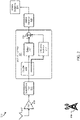
- FIG. 1 is a block diagram illustrating a system 100 for providing GNSS anti-jamming using interference cancellation.
- the system 100 receives GNSS signals and produces GNSS solutions 105.
- a larger navigation system may incorporate the system 100 and use the produced GNSS solutions 105 to create navigation solutions.
- the navigation solutions may describe the position, attitude, velocity, and other navigation information for a vehicle.
- the vehicle may be a boat, an automobile, a spacecraft, a missile, or other vehicle type.
- the GNSS solutions 105 may also apply to other movable objects, such as personal electronic devices, tracking devices, and other movable objects.
- a GNSS includes multiple satellites that orbit the earth and transmit signals.
- the system 100 includes a GNSS receiver that receives the transmitted signals and calculates position and velocity information when receiving signals from four or more GNSS satellites.
- the GNSS receiver may calculate pseudo-range, delta-range, carrier measurements, and C/No.
- a particular GNSS may include one or more of the United States developed Global Position System (GPS), the Russian developed Global Navigation Satellite System (GLONASS), the European Union developed Galileo system, and the Chinese Developed BeiDou system, among other global or regional satellite navigation systems.
- the system 100 receives signals through an antenna 107.
- the antenna 107 may include multiple antennas or a single antenna.
- the system 100 includes GNSS anti-jammer 101.
- the GNSS anti-jammer 101 may be hardware, software, or combination of software and hardware that receives signals through the antenna 107, where the signals include a weak portion that includes GNSS signals from GNSS satellites and a potential strong interference portion from the interfering signal source 106.
- the GNSS anti-jammer 101 includes a summer 119 and an interference isolator 134.
- the interference isolator 134 isolates the strong interference portion from the received signals and provides the isolated strong interference portion to the summer 119.
- the summer 119 then subtracts the strong interference portion from the receive signals. Accordingly, the summer 119 may provide a signal that is similar to the received signals from the GNSS satellites.
- the interference isolator 134 may also produce a noise measurement that is equal to noise generated within the interference isolator 134.
- the GNSS anti-jammer 101 may also include a local noise remover 108.
- the local noise remover 108 may be a processor that receives the summed signal from the summer 119 and an estimate of noise generated by the interference isolator 134.
- the local noise remover 108 may remove the noise from the summed signal by subtracting the noise estimate from the summed signal.
- the local noise remover 108 may provide an output signal for the GNSS anti-jammer 101 to a GNSS receiver 103.
- the GNSS receiver 103 uses the received signal to provide GNSS solutions 105.
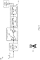
- FIG. 2 is block diagram illustrating a system 200 for providing GNSS anti-jamming using interference cancellation.
- the system 200 includes GNSS anti-jammer 201 that functions similarly to the GNSS anti-jammer 101 in FIG. 1 .
- the system 200 receives signals through an antenna 207, where the antenna 207 functions similarly to the antenna 107 in FIG. 1 .
- the system 200 may also include an LNA 209 that amplifies the signals received through the antenna 207 while limiting the introduction of noise into the amplified signals.
- the system 200 may include a band-pass filter 211 that filters out RF energy at frequencies outside of a passband associated with the GNSS signals.
- the band-pass filter 211 provides the filtered received signals to the GNSS anti-jammer 201 to remove potential interfering signals received from the interfering signal sources 206.
- the GNSS anti-jammer 201 cancels the interfering signals such that the GNSS receiver 203 can receive the GNSS signals absent the received interfering signals when calculating GNSS solutions 205.
- the GNSS anti-jammer 201 includes a coupler 213.
- the coupler 213 receives the filtered signal from the band-pass filter 211 through an input port and couples portions of the received filtered signal to different output ports. For example, the coupler 213 may couple fifty percent of the power to one output port and fifty percent of the power to the other output port.
- the GNSS anti-jammer 201 includes a delay path 215 coupled to one of the output ports of the coupler 213 and an interference isolation path 217 coupled to the other output port of the coupler 213.
- the GNSS anti-jammer 201 functions similarly to the interference isolator 134 in FIG. 1 .
- the GNSS anti-jammer 201 isolates the interfering signals from the interfering signal sources 206 by removing portions of the received signals associated with the GNSS satellites. Accordingly, the output of the interference isolation path 217 may be the portions of the signal that are associated with the signals from the interfering signal sources 206.
- the GNSS anti-jammer 201 may delay the signal by an amount of time associated with the time it takes for signals to pass through the interference isolation path 217. Accordingly, signals take the same time to pass through the delay path 215 and the interference isolation path 217 (signals are coherent).
- the GNSS anti-jammer 201 includes a summer 219 that adds different input signals into a single output. In some embodiments, the summer 219 may also negate one of the inputs to subtract the negated signal from the other non-negated signal. In the GNSS anti-jammer 201, the summer 219 may sum the output of the delay path 215 as a first input and the negated output of the interference isolation path 217 as a second input. Accordingly, the summer 219 may subtract the signals from the interfering signal sources 206 from the signals received through the antenna 207. Thus, the output summed signals of the summer 219 substantially contain the desired GNSS signal without the undesired signals from the interfering signal sources 206. The GNSS anti-jammer 201 provide the output from the summer 219 as an output for the GNSS anti-jammer 201.
- the GNSS receiver 203 receives the output from the GNSS anti-jammer 201. As the output from the GNSS anti-jammer 201 has removed the signals from the interfering signal sources 206, the signals from the interfering signal sources 206 may not affect the operation of the GNSS receiver 203.
- the GNSS receiver 203 may provide GNSS solutions 205 for use in the calculation of navigational information.
- FIG. 3 is a block diagram illustrating an additional embodiment of a system 300 for providing GNSS anti-jamming using interference cancellation.
- the system 300 includes GNSS interference rejection circuitry 333.
- the GNSS interference rejection circuitry 333 functions somewhat similarly to the GNSS anti-jammer 201 in FIG. 2 .
- the GNSS interference rejection circuitry 333 may provide different outputs as compared to the single output lacking the interfering signals described above concerning the GNSS anti-jammer 201.
- the GNSS interference rejection circuitry 333 receives signals through an antenna 307, where the antenna 307 is substantially similar to the antenna 107 in FIG. 1 .
- the received signals may include signals from GNSS satellites and, potentially, interfering signals from interfering signal sources 306 that may be similar to the interfering signal source 106.
- the signal received through the antenna 307 may be equal to S(t) represented by the equation (1) described above.
- the GNSS interference rejection circuitry 333 may provide two outputs from the received signals, an analog output S 1 ( t ) and a digital output w ⁇ 2 n ⁇ .
- the analog output S 1 ( t ) may be equal to S(t) minus the interfering signals but with added quantization noise.
- the analog output S 1 ( t ) may be provided to a local noise remover 308 that may function similar to the local noise remover 108 in FIG. 1 .
- the local noise remover 308 may include an ADC 335 and a digital summer 337.
- the ADC 335 may convert the analog output S 1 ( t ) to a digital signal S 1 ( n ).
- the ADC 335 provides the output digital signal S 1 ( n ) to a digital summer 337.
- the GNSS interference rejection circuitry 333 may provide a digital output w ⁇ 2 ( n ) that represents a quantization noise.
- the GNSS interference rejection circuitry 333 may provide the digital output w ⁇ 2 ( n ) to the digital summer 337 in the local noise remover 308.
- the digital summer 337 subtracts the digital output w ⁇ 2 ( n ) of the GNSS interference rejection circuitry 333 from the output digital signal S 1 ( n ) from the ADC 335 to produce a summed output S 2 ( n ) .
- the summed output S 2 ( n ) may be substantially equal to digitized versions of the signals received through the antenna 307 without interfering signals produced by the interfering signal sources 306.
- the digital summer 337 may function within the local noise remover 308 to remove noise generated by the GNSS interference rejection circuitry 333 from the signal provided by the ADC 335.
- the system 300 also includes a GNSS receiver 303 that functions similarly to the GNSS receiver 203.
- the GNSS receiver 303 may include a direct digital downconverter 339 and a GNSS digital engine 341.
- the direct digital downconverter 339 receives the digital output from the digital summer 337.
- the direct digital downconverter 339 converts the summer output to a digital baseband signal for use by the GNSS digital engine 341.
- the GNSS digital engine 341 processes the digitized GNSS signals to calculate GNSS navigational information.
- the GNSS digital engine 341 then provides GNSS solutions 305 for use by a larger navigation system, or for use by another system or device. The removal of the interfering signals reduces the impact of the interference on the GNSS solutions 305.
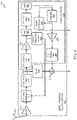
- FIG. 4 is a block diagram of system 400 that illustrates a detailed embodiment of GNSS interference rejection circuitry 433 that functions similarly to the GNSS interference rejection circuitry 333 in FIG. 3 . Similar to the GNSS interference rejection circuitry 333, the GNSS interference rejection circuitry 433 receives a signal from an antenna 407 that functions similarly to the antenna 307. Similarly, the GNSS interference rejection circuitry 433 provides an output to local noise remover such as the local noise remover 308.
- the GNSS interference rejection circuitry 433 couples the signal from the antenna 407 into an LNA 409.
- the LNA 409 may function similarly to the LNA 209 in FIG. 2 .
- the GNSS interference rejection circuitry 433 may couple the output of the LNA 409 into a variable attenuator 443.
- the variable attenuator 443 ensures that the signal provided by the variable attenuator 443 is within a dynamic range of an ADC, like the ADC 451.
- the GNSS interference rejection circuitry 433 may remain functional when a strong signal causes components of the GNSS interference rejection circuitry 433 to operate non-linearly, the GNSS interference rejection circuitry 433 may prevent damage to components of the GNSS interference rejection circuitry 433 due to the reception of strong signals.
- the GNSS interference rejection circuitry 433 couples the output of the variable attenuator 443 into a band-pass filter 445.
- the band-pass filter 445 may function similarly to the band-pass filter 211 in FIG. 2 .
- the GNSS interference rejection circuitry 433 includes a coupler 447 that functions similarly to the coupler 213 in FIG. 2 .
- the coupler 447 couples a portion of the filtered signal into the delay 469 and a portion into an interference isolation path that functions like the interference isolation path 217.
- the delay 469 may be analog circuitry that delays a signal so that the portion of the signal passing through the delay 469 and the portion of the signal passing through the interference isolation path are equal in phase or are time aligned upon arrival at an analog summer 419.
- the GNSS interference rejection circuitry 433 includes an interference isolator 434.
- the interference isolator 434 includes components associated with the interference isolation path.
- the interference isolator 434 includes components on the signal path between an anti-aliasing filter 449 and an anti-imaging filter 467.
- the anti-aliasing filter 449 may receive the input from the coupler 447 and filter noise outside the Nyquist band before converting the signal to the digital domain.
- an ADC 451 may convert the RF, analog, received signals to the digital domain to create a digital GNSS signal.
- variable attenuator control 453 may monitor the signal for determining whether or not to attenuate the received signal due to the strength of the signal and how much the received signal should be attenuated. The variable attenuator control 453 may then direct the operation of the variable attenuator 443.
- the output of the ADC 451 may be coupled into the input of a fast Fourier transform (FFT) 455.
- the FFT 455 may transform the digitized signal into the frequency domain and provide the output to the zero-out bins 457.
- the zero-out bins 457 may identify the frequency bins with the strongest signals (associated with the strong interference portion) and zero out the other bins (associated with the weak portion) with a signal power less than a determined power level threshold.
- the zero-out bins 457 may identify the frequency bin having the signal component of the largest magnitude and then zero out frequency bins with signal components having a signal power with magnitudes less than a threshold percentage of the largest magnitude.
- the zero-out bins 457 may identify an expected magnitude level associated with the highest expected magnitude for GNSS signals, where the zero-out bins 457 zeros out the frequency bins that are less than or equal to the highest expected magnitude for GNSS signals.
- the zero-out bins 457 When the zero-out bins 457 has zeroed-out the different frequency bins, the zero-out bins 457 provides the signal to an inverse fast Fourier transform (IFFT) 459.
- IFFT inverse fast Fourier transform
- the IFFT 459 transforms the signal in the frequency domain back into the time domain.
- the signal produced by the IFFT 459 may be substantially equal to J n ⁇ , a digital estimate of the interfering signal received from an interfering signal source, the digital estimate may also be referred to as the estimated strong interference portion of the received signals.
- the GNSS interference rejection circuitry 433 may further include a quantizer 461.
- the quantizer 461 quantizes the estimated digital interfering signal equal to the number of bits used by a digital-to-analog converter (DAC), such as the subsequent DAC 465.
- the quantization of the estimated digital interfering signal may be represented by J n ⁇ + w ⁇ 2 n , where the w ⁇ 2 ( n ) represents quantization noise having a variance of ⁇ 2 and a mean of ⁇ 2 .
- the GNSS interference rejection circuitry 433 may also include a noise estimator 463.
- the noise estimator 463 estimates the quantization noise by identifying the difference between the estimated digital interfering signal before quantization and the estimated digital interfering signal after quantization by the quantizer 461.
- the noise estimator 463 then provides a quantization noise estimate w ⁇ 2 n ⁇ to a digital summer such as the digital summer 337 shown in FIG. 3 , where the digital summer 337 subtracts the quantization noise estimate w ⁇ 2 n ⁇ from another signal.
- the DAC 465 may convert the quantized signal back into the analog domain.
- the GNSS interference rejection circuitry 433 may also include an anti-imaging filter 467.
- the anti-imaging filter 467 is a low-pass filter that filters out higher frequency images of the signal caused by the digital-to-analog conversion.
- the GNSS interference rejection circuitry 433 may provide the output of the anti-imaging filter 467, which represents the interfering signal and quantization noise, to the analog summer 419.
- the analog summer 419 subtracts the output of the anti-imaging filter 467 from the signal provided by the delay 469 to produce the analog output S 1 ( t ) . Accordingly, the GNSS interference rejection circuitry 433 may produce an analog output S 1 ( t ) and a digital output w ⁇ 2 ( n ) as described above concerning the GNSS interference rejection circuitry 333 in FIG 3 .
- the GNSS interference rejection circuitry 433 may include a processor and a memory unit, where the memory unit stores information that can aid the processor when performing some of the functions of the GNSS interference rejection circuitry 433.
- a processor may perform some of the digital operations of the GNSS interference rejection circuitry 433, like the FFT 455, zero-out bins 457, IFFT 459, quantizer 461, and the noise estimator 463.
- the processor may also perform other functions that may include the digital summer 337, the direct digital downconverter 339, the GNSS digital engine 341, among other digital operations.
- the processor may be implemented using software, firmware, hardware, or other appropriate combinations thereof.
- the processor and/or other computational devices may be supplemented by, or incorporated in, specially designed application-specific integrated circuits (ASICs) or field programmable gate arrays (FPGAs).
- ASICs application-specific integrated circuits
- FPGAs field programmable gate arrays
- the processor may be a general or special purpose computer or processor, or other programmable logic devices.
- the processor and other competition devices may also include or function with software programs, firmware, or other computer-readable instructions for carrying out various process tasks, calculations, and control functions used in the present methods and systems.
- computer-executable instructions may implement the methods described in this description.
- At least one processor may execute the computer-executable instructions.
- Software, firmware, or other execution-capable devices may execute the computer-readable instructions for carrying out various process tasks, calculations, and generation of data used in the operations of the described methods.
- the computer-readable instructions may be stored as part of one or more appropriate computer-program products, where a computer-program product may be a set of computer-readable instructions or data structures stored on a computer-readable medium.
- the computer-readable medium may be a media that stores data that can be accessed by the processor or other computing device. In certain implementations, the computer-readable medium may form part of a memory unit.
- Non-volatile memory devices may include semiconductor memory devices such as random access memory (RAM), read-only memory (ROM), electrically erasable programmable ROM (EEPROM), or flash memory devices.
- the non-volatile memory devices may also include magnetic disks (such as internal hard disks or removable disks), optical storage devices (such as compact discs (CDs), digital versatile discs (DVDs), Blu-ray discs), or other media that can store computer-executable instructions or data structures.
- FIG. 5 is a flowchart diagram of a method 500 performed by an interference isolator to isolate a strong interference portion from the signals received through an antenna.
- the interference isolator may function similar to the interference isolator 134 and the interference isolator 434.
- the method 500 proceeds at 501, where noise is filtered from the received signals outside the Nyquist band. The filtering can be performed as described above concerning the anti-aliasing filter 449 in FIG. 4 .
- the method 500 proceeds at 503, where the received signals are converted into digital received signals.
- an ADC like the ADC 451 in FIG. 4 may convert the analog filtered signal into a digital signal for processing by a processor.
- the method 500 proceeds at 505, where the digital received signals are transformed into the frequency domain.
- a processor may perform an FFT, a Z transform, a Laplace transform, a wavelet transform, or other type of frequency-domain method on the digital samples of the received signal.
- the method 500 proceeds at 507, where frequency bins having a lower power than a power level threshold are zeroed-out. By zeroing out the frequency bins, having the lower power levels, the processor is removing frequency components that are not associated with the strong interference portion.
- the method 500 then proceeds to 509, where the digital signals are transformed into the time domain.
- the processor may perform an IFFT, an inverse Z transform, an inverse Laplace transform, an inverse wavelet transform, or other transform for transforming the domain for signals into the time domain.
- the method 500 when the signals are in the time domain, the method 500 proceed at 511, where the digital signals are quantized. As discussed above, quantization changes the bits within a signal to prepare the signal to have the correct number of bits for conversion by a DAC. Accordingly, after quantization, the method 500 proceeds at 513, where the digital signals are converted to analog signals. After conversion, the method 500 proceeds at 515, where anti-imaging filtering is performed on the analog signals. After performing the anti-imaging filtering, the interference isolator proceeds at 517, where an analog strong interference portion is provided for subtraction from the received signals.
- FIG. 6 is a flowchart diagram of a method 600 for providing GNSS anti-jamming using interference cancellation.
- the method 600 may proceed at 601, where signals are received, wherein the signals comprise a weak portion associated with GNSS satellites and a strong interference portion. Further, the method 600 may proceed at 603, where the strong interference portion is isolated from the received signals. Also, the method 600 may proceed at 605, where the strong interference portion is subtracted from the received signals to create a summed signal. Moreover, the method 600 may proceed at 607, where the noise generated during the isolation of the strong interference portion is digitally removed from the summed signal.
Landscapes
- Engineering & Computer Science (AREA)
- Radar, Positioning & Navigation (AREA)
- Remote Sensing (AREA)
- Computer Networks & Wireless Communication (AREA)
- Physics & Mathematics (AREA)
- General Physics & Mathematics (AREA)
- Signal Processing (AREA)
- Noise Elimination (AREA)
Abstract
Description
- This application claims benefit of
Indian Provisional Patent Application Serial No. 202011051101, same title herewith, filed on November 24, 2020 - Many navigation systems receive measurements from satellites in a global navigation satellite system (GNSS). These navigation systems use the signals from the GNSS satellites to determine position and velocity information of an associated object, such as an aircraft, boat, automobile, personal electronic device, or other moving objects. These navigation systems also use measurements acquired from the GNSS signals to bound drifts in measurements obtained from different sensors coupled to a navigation system.
- Recently, the integrity, accuracy, and performance of navigation systems that use GNSS signals have come under threat because of the rise of GNSS jamming activities. GNSS jamming activities occur when a device other than the GNSS satellites transmits signals near the frequencies of the GNSS signals, where the interfering signals are stronger than the GNSS signals. The interfering signals potentially interfere with the accurate reception of the authentic GNSS signals.
- Systems and methods for GNSS anti-jamming using interference cancellation are described herein. In certain embodiments, a system includes an antenna that receives signals, wherein the signals comprise a weak portion associated with one or more GNSS satellites and a strong interference portion from an interfering signal source. The system also includes a GNSS anti-jammer. The GNSS anti-jammer includes an interference isolator that receives the received signals and provides an estimated strong interference portion as an output. The GNSS anti-jammer also includes a summer that subtracts the estimated strong interference portion from the received signals to create a summed signal. Further, the GNSS anti-jammer includes a local noise remover that removes noise generated by the interference isolator from the summed signal, wherein the local noise remover is a processor that digitally removes the noise. Further, the system includes a GNSS receiver coupled to receive the summed signal from the processor.
- Drawings accompany this description and depict only some embodiments associated with the scope of the appended claims. Thus, the described and depicted embodiments should not be considered limiting in scope. The accompanying drawings and specification describe the exemplary embodiments and features thereof, with additional specificity and detail, in which:
-
FIG. 1 is a block diagram illustrating a system for providing GNSS anti-jamming using interference cancellation according to an aspect of the present disclosure; -
FIG. 2 is a block diagram illustrating a system for providing GNSS anti-jamming using interference cancellation according to an aspect of the present disclosure; -
FIG. 3 is a block diagram illustrating a system for providing GNSS anti-jamming using interference cancellation according to an aspect of the present disclosure; -
FIG. 4 is a block diagram illustrating a system for providing GNSS anti-jamming using interference cancellation according to an aspect of the present disclosure; -
FIG. 5 is a flowchart diagram of a method for isolating an interfering signal according to an aspect of the present disclosure; and -
FIG. 6 is a flowchart diagram of a method for providing GNSS anti-jamming using interference cancellation according to an aspect of the present disclosure. - Under common practice, the various described features are not drawn to scale but are drawn to emphasize specific features relevant to the example embodiments.
- In the following detailed description, reference is made to the accompanying drawings that form a part of the present description, and in which is shown, through illustration, specific illustrative embodiments. However, it is to be understood that other embodiments may be used and that logical, mechanical, and electrical changes may be made.
- The present disclosure describes systems and methods for providing GNSS anti-jamming using interference cancellation. In particular, the systems and methods cancel an interfering signal in the analog domain to ensure that the interfering signal does not compromise the GNSS receiver's dynamic range. The system extracts the interfering signal from the received signals and subtracts the interfering signal from the received signal in the analog domain. The system then provides the signal lacking the interfering signal to a GNSS receiver.
- In some situations, a GNSS receiver may be used in an environment containing an interfering signal source. For example, when in the presence of the interfering signal source, the GNSS receiver can receive signals that include the GNSS signals from GNSS satellites and interfering signals from the interfering signal source. The signals received at the antenna may be represented by the following equation:

- An interfering signal source may emit a signal near the frequencies of the GNSS signals from the GNSS satellites. However, as the interfering signal source is substantially closer to the GNSS receiver than the GNSS satellites, the strength of the interfering signal received from the interfering signal source can be stronger than the GNSS signals received from the GNSS satellites. Accordingly, the GNSS receiver may receive signals that include a weak portion associated with the GNSS satellites and a strong interference portion associated with the interfering signal source.
- The higher strength of the interfering signals received from the interfering signal source can negatively affect the operation of the GNSS receiver. For example, as the frequencies of the interfering signals from the interfering signal source are close to the frequency of the GNSS signals from the satellites, the filtering of the signals received by the GNSS receiver may pass the interfering signals along with the GNSS signals. As the strength of the interfering signals is greater than the strength of the GNSS signals, the signal can potentially saturate amplifiers and/or ADCs within the GNSS receiver. The saturated components within the GNSS receiver may cause a loss of data in the signals produced by the GNSS receiver.
-
FIG. 1 is a block diagram illustrating asystem 100 for providing GNSS anti-jamming using interference cancellation. Thesystem 100 receives GNSS signals and producesGNSS solutions 105. A larger navigation system may incorporate thesystem 100 and use the produced GNSSsolutions 105 to create navigation solutions. The navigation solutions may describe the position, attitude, velocity, and other navigation information for a vehicle. The vehicle may be a boat, an automobile, a spacecraft, a missile, or other vehicle type. The GNSSsolutions 105 may also apply to other movable objects, such as personal electronic devices, tracking devices, and other movable objects. - As used in this description, a GNSS includes multiple satellites that orbit the earth and transmit signals. The
system 100 includes a GNSS receiver that receives the transmitted signals and calculates position and velocity information when receiving signals from four or more GNSS satellites. For example, the GNSS receiver may calculate pseudo-range, delta-range, carrier measurements, and C/No. A particular GNSS may include one or more of the United States developed Global Position System (GPS), the Russian developed Global Navigation Satellite System (GLONASS), the European Union developed Galileo system, and the Chinese Developed BeiDou system, among other global or regional satellite navigation systems. - The
system 100 receives signals through anantenna 107. Theantenna 107 may include multiple antennas or a single antenna. To provide GNSS anti-jamming using interference cancellation, thesystem 100 includes GNSS anti-jammer 101. The GNSS anti-jammer 101 may be hardware, software, or combination of software and hardware that receives signals through theantenna 107, where the signals include a weak portion that includes GNSS signals from GNSS satellites and a potential strong interference portion from theinterfering signal source 106. - The GNSS anti-jammer 101 includes a
summer 119 and aninterference isolator 134. Theinterference isolator 134 isolates the strong interference portion from the received signals and provides the isolated strong interference portion to thesummer 119. Thesummer 119 then subtracts the strong interference portion from the receive signals. Accordingly, thesummer 119 may provide a signal that is similar to the received signals from the GNSS satellites. In some embodiments, theinterference isolator 134 may also produce a noise measurement that is equal to noise generated within theinterference isolator 134. - In certain embodiments, the GNSS anti-jammer 101 may also include a
local noise remover 108. Thelocal noise remover 108 may be a processor that receives the summed signal from thesummer 119 and an estimate of noise generated by theinterference isolator 134. Thelocal noise remover 108 may remove the noise from the summed signal by subtracting the noise estimate from the summed signal. Thelocal noise remover 108 may provide an output signal for the GNSS anti-jammer 101 to aGNSS receiver 103. TheGNSS receiver 103 uses the received signal to provideGNSS solutions 105. -
FIG. 2 is block diagram illustrating asystem 200 for providing GNSS anti-jamming using interference cancellation. Thesystem 200 includesGNSS anti-jammer 201 that functions similarly to the GNSS anti-jammer 101 inFIG. 1 . Thesystem 200 receives signals through an antenna 207, where the antenna 207 functions similarly to theantenna 107 inFIG. 1 . Thesystem 200 may also include anLNA 209 that amplifies the signals received through the antenna 207 while limiting the introduction of noise into the amplified signals. Additionally, thesystem 200 may include a band-pass filter 211 that filters out RF energy at frequencies outside of a passband associated with the GNSS signals. The band-pass filter 211 provides the filtered received signals to the GNSS anti-jammer 201 to remove potential interfering signals received from the interferingsignal sources 206. - As discussed above in
FIG. 1 , the GNSS anti-jammer 201 cancels the interfering signals such that theGNSS receiver 203 can receive the GNSS signals absent the received interfering signals when calculatingGNSS solutions 205. The GNSS anti-jammer 201 includes acoupler 213. Thecoupler 213 receives the filtered signal from the band-pass filter 211 through an input port and couples portions of the received filtered signal to different output ports. For example, thecoupler 213 may couple fifty percent of the power to one output port and fifty percent of the power to the other output port. - In exemplary embodiments, the GNSS anti-jammer 201 includes a
delay path 215 coupled to one of the output ports of thecoupler 213 and aninterference isolation path 217 coupled to the other output port of thecoupler 213. On theinterference isolation path 217, the GNSS anti-jammer 201 functions similarly to theinterference isolator 134 inFIG. 1 . Along theinterference isolation path 217, the GNSS anti-jammer 201 isolates the interfering signals from the interferingsignal sources 206 by removing portions of the received signals associated with the GNSS satellites. Accordingly, the output of theinterference isolation path 217 may be the portions of the signal that are associated with the signals from the interferingsignal sources 206. On thedelay path 215, the GNSS anti-jammer 201 may delay the signal by an amount of time associated with the time it takes for signals to pass through theinterference isolation path 217. Accordingly, signals take the same time to pass through thedelay path 215 and the interference isolation path 217 (signals are coherent). - In some embodiments, the GNSS anti-jammer 201 includes a
summer 219 that adds different input signals into a single output. In some embodiments, thesummer 219 may also negate one of the inputs to subtract the negated signal from the other non-negated signal. In theGNSS anti-jammer 201, thesummer 219 may sum the output of thedelay path 215 as a first input and the negated output of theinterference isolation path 217 as a second input. Accordingly, thesummer 219 may subtract the signals from the interferingsignal sources 206 from the signals received through the antenna 207. Thus, the output summed signals of thesummer 219 substantially contain the desired GNSS signal without the undesired signals from the interferingsignal sources 206. The GNSS anti-jammer 201 provide the output from thesummer 219 as an output for theGNSS anti-jammer 201. - The
GNSS receiver 203 receives the output from theGNSS anti-jammer 201. As the output from the GNSS anti-jammer 201 has removed the signals from the interferingsignal sources 206, the signals from the interferingsignal sources 206 may not affect the operation of theGNSS receiver 203. TheGNSS receiver 203 may provideGNSS solutions 205 for use in the calculation of navigational information. -
FIG. 3 is a block diagram illustrating an additional embodiment of asystem 300 for providing GNSS anti-jamming using interference cancellation. As illustrated, thesystem 300 includes GNSSinterference rejection circuitry 333. The GNSSinterference rejection circuitry 333 functions somewhat similarly to the GNSS anti-jammer 201 inFIG. 2 . However, the GNSSinterference rejection circuitry 333 may provide different outputs as compared to the single output lacking the interfering signals described above concerning theGNSS anti-jammer 201. - In exemplary embodiments, the GNSS
interference rejection circuitry 333 receives signals through anantenna 307, where theantenna 307 is substantially similar to theantenna 107 inFIG. 1 . As described above, the received signals may include signals from GNSS satellites and, potentially, interfering signals from interferingsignal sources 306 that may be similar to the interferingsignal source 106. The signal received through theantenna 307 may be equal to S(t) represented by the equation (1) described above. - In certain embodiments, the GNSS
interference rejection circuitry 333 may provide two outputs from the received signals, an analog output S1 (t) and a digital output

local noise remover 308 that may function similar to thelocal noise remover 108 inFIG. 1 . Thelocal noise remover 308 may include anADC 335 and adigital summer 337. TheADC 335 may convert the analog output S1 (t) to a digital signal S1 (n). TheADC 335 provides the output digital signal S1 (n) to adigital summer 337. - In addition to the analog output S1 (t), the GNSS
interference rejection circuitry 333 may provide a digital output w ∂2 (n) that represents a quantization noise. The GNSSinterference rejection circuitry 333 may provide the digital output w ∂2 (n) to thedigital summer 337 in thelocal noise remover 308. Thedigital summer 337 subtracts the digital output w ∂2 (n) of the GNSSinterference rejection circuitry 333 from the output digital signal S1 (n) from theADC 335 to produce a summed output S2 (n). The summed output S2 (n) may be substantially equal to digitized versions of the signals received through theantenna 307 without interfering signals produced by the interferingsignal sources 306. Thus, thedigital summer 337 may function within thelocal noise remover 308 to remove noise generated by the GNSSinterference rejection circuitry 333 from the signal provided by theADC 335. - The
system 300 also includes aGNSS receiver 303 that functions similarly to theGNSS receiver 203. In some implementations, theGNSS receiver 303 may include a directdigital downconverter 339 and a GNSSdigital engine 341. The directdigital downconverter 339 receives the digital output from thedigital summer 337. The directdigital downconverter 339 converts the summer output to a digital baseband signal for use by the GNSSdigital engine 341. The GNSSdigital engine 341 processes the digitized GNSS signals to calculate GNSS navigational information. The GNSSdigital engine 341 then providesGNSS solutions 305 for use by a larger navigation system, or for use by another system or device. The removal of the interfering signals reduces the impact of the interference on theGNSS solutions 305. -
FIG. 4 is a block diagram ofsystem 400 that illustrates a detailed embodiment of GNSSinterference rejection circuitry 433 that functions similarly to the GNSSinterference rejection circuitry 333 inFIG. 3 . Similar to the GNSSinterference rejection circuitry 333, the GNSSinterference rejection circuitry 433 receives a signal from anantenna 407 that functions similarly to theantenna 307. Similarly, the GNSSinterference rejection circuitry 433 provides an output to local noise remover such as thelocal noise remover 308. - In exemplary embodiments, the GNSS
interference rejection circuitry 433 couples the signal from theantenna 407 into anLNA 409. TheLNA 409 may function similarly to theLNA 209 inFIG. 2 . The GNSSinterference rejection circuitry 433 may couple the output of theLNA 409 into avariable attenuator 443. Thevariable attenuator 443 ensures that the signal provided by thevariable attenuator 443 is within a dynamic range of an ADC, like theADC 451. While the GNSSinterference rejection circuitry 433 may remain functional when a strong signal causes components of the GNSSinterference rejection circuitry 433 to operate non-linearly, the GNSSinterference rejection circuitry 433 may prevent damage to components of the GNSSinterference rejection circuitry 433 due to the reception of strong signals. - In further embodiments, the GNSS
interference rejection circuitry 433 couples the output of thevariable attenuator 443 into a band-pass filter 445. The band-pass filter 445 may function similarly to the band-pass filter 211 inFIG. 2 . Also, the GNSSinterference rejection circuitry 433 includes acoupler 447 that functions similarly to thecoupler 213 inFIG. 2 . Thecoupler 447 couples a portion of the filtered signal into thedelay 469 and a portion into an interference isolation path that functions like theinterference isolation path 217. As the interference isolation path includes multiple electronic components, thedelay 469 may be analog circuitry that delays a signal so that the portion of the signal passing through thedelay 469 and the portion of the signal passing through the interference isolation path are equal in phase or are time aligned upon arrival at ananalog summer 419. - In certain embodiments, the GNSS
interference rejection circuitry 433 includes aninterference isolator 434. Theinterference isolator 434 includes components associated with the interference isolation path. For example, theinterference isolator 434 includes components on the signal path between ananti-aliasing filter 449 and ananti-imaging filter 467. Theanti-aliasing filter 449 may receive the input from thecoupler 447 and filter noise outside the Nyquist band before converting the signal to the digital domain. After performing the anti-aliasing filtering, anADC 451 may convert the RF, analog, received signals to the digital domain to create a digital GNSS signal. In some embodiments, after digitization, avariable attenuator control 453 may monitor the signal for determining whether or not to attenuate the received signal due to the strength of the signal and how much the received signal should be attenuated. Thevariable attenuator control 453 may then direct the operation of thevariable attenuator 443. - In additional embodiments, the output of the
ADC 451 may be coupled into the input of a fast Fourier transform (FFT) 455. TheFFT 455 may transform the digitized signal into the frequency domain and provide the output to the zero-outbins 457. The zero-outbins 457 may identify the frequency bins with the strongest signals (associated with the strong interference portion) and zero out the other bins (associated with the weak portion) with a signal power less than a determined power level threshold. For example, the zero-outbins 457 may identify the frequency bin having the signal component of the largest magnitude and then zero out frequency bins with signal components having a signal power with magnitudes less than a threshold percentage of the largest magnitude. Alternatively, the zero-outbins 457 may identify an expected magnitude level associated with the highest expected magnitude for GNSS signals, where the zero-outbins 457 zeros out the frequency bins that are less than or equal to the highest expected magnitude for GNSS signals. - When the zero-out
bins 457 has zeroed-out the different frequency bins, the zero-outbins 457 provides the signal to an inverse fast Fourier transform (IFFT) 459. TheIFFT 459 transforms the signal in the frequency domain back into the time domain. The signal produced by theIFFT 459 may be substantially equal to
- The GNSS
interference rejection circuitry 433 may further include aquantizer 461. Thequantizer 461 quantizes the estimated digital interfering signal equal to the number of bits used by a digital-to-analog converter (DAC), such as thesubsequent DAC 465. The quantization of the estimated digital interfering signal may be represented by
quantizer 461, the GNSSinterference rejection circuitry 433 may also include anoise estimator 463. Thenoise estimator 463 estimates the quantization noise by identifying the difference between the estimated digital interfering signal before quantization and the estimated digital interfering signal after quantization by thequantizer 461. Thenoise estimator 463 then provides a quantization noise estimate
digital summer 337 shown inFIG. 3 , where thedigital summer 337 subtracts the quantization noise estimate
- In exemplary embodiments, after quantization by the
quantizer 461, theDAC 465 may convert the quantized signal back into the analog domain. The GNSSinterference rejection circuitry 433 may also include ananti-imaging filter 467. Theanti-imaging filter 467 is a low-pass filter that filters out higher frequency images of the signal caused by the digital-to-analog conversion. The GNSSinterference rejection circuitry 433 may provide the output of theanti-imaging filter 467, which represents the interfering signal and quantization noise, to theanalog summer 419. Theanalog summer 419 subtracts the output of theanti-imaging filter 467 from the signal provided by thedelay 469 to produce the analog output S1 (t). Accordingly, the GNSSinterference rejection circuitry 433 may produce an analog output S1 (t) and a digital output w ∂2(n) as described above concerning the GNSSinterference rejection circuitry 333 inFIG 3 . - In certain embodiments, the GNSS
interference rejection circuitry 433 may include a processor and a memory unit, where the memory unit stores information that can aid the processor when performing some of the functions of the GNSSinterference rejection circuitry 433. For example, a processor may perform some of the digital operations of the GNSSinterference rejection circuitry 433, like theFFT 455, zero-outbins 457,IFFT 459,quantizer 461, and thenoise estimator 463. The processor may also perform other functions that may include thedigital summer 337, the directdigital downconverter 339, the GNSSdigital engine 341, among other digital operations. - The processor may be implemented using software, firmware, hardware, or other appropriate combinations thereof. The processor and/or other computational devices may be supplemented by, or incorporated in, specially designed application-specific integrated circuits (ASICs) or field programmable gate arrays (FPGAs). The processor may be a general or special purpose computer or processor, or other programmable logic devices. The processor and other competition devices may also include or function with software programs, firmware, or other computer-readable instructions for carrying out various process tasks, calculations, and control functions used in the present methods and systems.
- Further, computer-executable instructions (such as program modules or components) may implement the methods described in this description. At least one processor may execute the computer-executable instructions. Software, firmware, or other execution-capable devices may execute the computer-readable instructions for carrying out various process tasks, calculations, and generation of data used in the operations of the described methods. The computer-readable instructions may be stored as part of one or more appropriate computer-program products, where a computer-program product may be a set of computer-readable instructions or data structures stored on a computer-readable medium. The computer-readable medium may be a media that stores data that can be accessed by the processor or other computing device. In certain implementations, the computer-readable medium may form part of a memory unit.
- Computer-readable mediums may include non-volatile memory devices. Non-volatile memory devices may include semiconductor memory devices such as random access memory (RAM), read-only memory (ROM), electrically erasable programmable ROM (EEPROM), or flash memory devices. The non-volatile memory devices may also include magnetic disks (such as internal hard disks or removable disks), optical storage devices (such as compact discs (CDs), digital versatile discs (DVDs), Blu-ray discs), or other media that can store computer-executable instructions or data structures.
-
FIG. 5 is a flowchart diagram of amethod 500 performed by an interference isolator to isolate a strong interference portion from the signals received through an antenna. The interference isolator may function similar to theinterference isolator 134 and theinterference isolator 434. Themethod 500 proceeds at 501, where noise is filtered from the received signals outside the Nyquist band. The filtering can be performed as described above concerning theanti-aliasing filter 449 inFIG. 4 . Additionally, themethod 500 proceeds at 503, where the received signals are converted into digital received signals. For example, an ADC like theADC 451 inFIG. 4 may convert the analog filtered signal into a digital signal for processing by a processor. - In additional embodiments, the
method 500 proceeds at 505, where the digital received signals are transformed into the frequency domain. For example, a processor may perform an FFT, a Z transform, a Laplace transform, a wavelet transform, or other type of frequency-domain method on the digital samples of the received signal. When in the frequency domain, themethod 500 proceeds at 507, where frequency bins having a lower power than a power level threshold are zeroed-out. By zeroing out the frequency bins, having the lower power levels, the processor is removing frequency components that are not associated with the strong interference portion. Themethod 500 then proceeds to 509, where the digital signals are transformed into the time domain. For example, the processor may perform an IFFT, an inverse Z transform, an inverse Laplace transform, an inverse wavelet transform, or other transform for transforming the domain for signals into the time domain. - In some embodiments, when the signals are in the time domain, the
method 500 proceed at 511, where the digital signals are quantized. As discussed above, quantization changes the bits within a signal to prepare the signal to have the correct number of bits for conversion by a DAC. Accordingly, after quantization, themethod 500 proceeds at 513, where the digital signals are converted to analog signals. After conversion, themethod 500 proceeds at 515, where anti-imaging filtering is performed on the analog signals. After performing the anti-imaging filtering, the interference isolator proceeds at 517, where an analog strong interference portion is provided for subtraction from the received signals. -
FIG. 6 is a flowchart diagram of amethod 600 for providing GNSS anti-jamming using interference cancellation. Themethod 600 may proceed at 601, where signals are received, wherein the signals comprise a weak portion associated with GNSS satellites and a strong interference portion. Further, themethod 600 may proceed at 603, where the strong interference portion is isolated from the received signals. Also, themethod 600 may proceed at 605, where the strong interference portion is subtracted from the received signals to create a summed signal. Moreover, themethod 600 may proceed at 607, where the noise generated during the isolation of the strong interference portion is digitally removed from the summed signal. -
- Example 1 includes a system comprising: an antenna that receives signals, wherein the signals comprise a weak portion associated with one or more GNSS satellites and a strong interference portion from an interfering signal source; a GNSS anti-jammer comprising: an interference isolator that receives the received signals and provides an estimated strong interference portion as an output; a summer that subtracts the estimated strong interference portion from the received signals to create a summed signal; and a local noise remover that removes noise generated by the interference isolator from the summed signal, wherein the local noise remover is a processor that digitally removes the noise; and a GNSS receiver coupled to receive the summed signal from the local noise remover.
- Example 2 includes the system of Example 1, wherein the interference isolator includes an analog-to-digital converter to convert the received signals into digital signals.
- Example 3 includes the system of Example 2, wherein the interference isolator: performs a fast Fourier transform on the digital signals; removes the weak portion of the digital signals to isolate the strong interference portion to create the estimated strong interference portion; and performs an inverse fast Fourier transform on the estimated strong interference portion.
- Example 4 includes the system of Example 3, wherein the interference isolator removes the weak portion by setting frequency bins to zero that have a signal power less than a determined power level threshold.
- Example 5 includes the system of any of Examples 1-4, wherein the interference isolator comprises a quantizer to quantize the estimated strong interference portion to a number of bits used by a digital-to-analog converter.
- Example 6 includes the system of Example 5, wherein the interference isolator comprises a noise estimator to estimate the noise, wherein the noise is introduced by the quantizer into the estimated strong interference portion.
- Example 7 includes the system of Example 6, wherein the local noise remover is a digital summer that subtracts the estimated noise from the summed signal.
- Example 8 includes the system of any of Examples 1-7, wherein the summer is an analog summer.
- Example 9 includes the system of any of Examples 1-8, wherein the interference isolator comprises a variable attenuator control that attenuates the received signals based on a detected signal strength of the received signals.
- Example 10 includes the system of any of Examples 1-9, further comprising a delay that delays the received signals that is an input for the summer by a time used by the interference isolator to isolate the strong interference portion.
- Example 11 includes a method comprising: receiving signals, wherein the received signals comprise a weak portion associated with one or more GNSS satellites and a strong interference portion; isolating the strong interference portion from the received signals; subtracting the strong interference portion from the received signals to create a summed signal; and digitally removing noise generated during the isolation of the strong interference portion from the summed signal.
- Example 12 includes the method of Example 11, further comprising converting the received signals into digital signals.
- Example 13 includes the method of Example 12, further comprising: performing a fast Fourier transform on the digital signals; removing the weak portion of the digital signals to isolate the strong interference portion to create an estimated strong interference portion; and performing an inverse fast Fourier transform on the estimated strong interference portion.
- Example 14 includes the method of Example 13, wherein removing the weak portion comprises setting frequency bins to zero that have a signal power less than a determined power level threshold.
- Example 15 includes the method of any of Examples 11-14, further comprising quantizing an estimate of the strong interference portion to a number of bits used by a digital-to-analog converter.
- Example 16 includes the method of Example 15, further comprising estimating the noise introduced during the quantization of the estimated strong interference portion.
- Example 17 includes the method of Example 16, wherein digitally removing the noise comprises digitally subtracting the estimated noise from the summed signal.
- Example 18 includes the method of any of Examples 11-17, further comprising attenuating the received signals based on a detected signal strength of the received signals.
- Example 19 includes the method of any of Examples 11-18, further comprising delaying the received GNSS signal from which the strong interference portion is subtracted by a time used to isolate the strong interference portion.
- Example 20 includes a system comprising: an antenna that receives signals, wherein the received signals comprise a weak portion associated with one or more GNSS satellites and a strong interference portion; an interference isolator that receives the received signals as an input and provides an estimated strong interference portion as an output, wherein the interference isolator: converts the received signals into digital signals; performs a fast Fourier transform on the digital signals; removes the weak portion of the digital signals to isolate the strong interference portion to create the estimated strong interference portion; performs an inverse fast Fourier transform on the estimated strong interference portion; quantizes the estimated strong interference portion to a number of bits used by a digital-to-analog converter; estimates noise generated during quantization of the estimated strong interference portion; and converts the estimated strong interference portion to an analog estimated strong interference portion; a summer that subtracts the analog estimated strong interference portion from the received signals to create a summed signal; a local noise remover that digitally removes the estimated noise from the summed signal; and a GNSS receiver coupled to receive the summed signal.
- Although specific embodiments have been illustrated and described herein, it will be appreciated by those of ordinary skill in the art that any arrangement, which is calculated to achieve the same purpose, may be substituted for the specific embodiments shown. Therefore, it is manifestly intended that this invention be limited only by the claims and the equivalents thereof.
Claims (10)
- A system comprising:an antenna (107) that receives signals, wherein the signals comprise a weak portion associated with one or more GNSS satellites and a strong interference portion from an interfering signal source (106);a GNSS anti-jammer (101) comprising:an interference isolator (134) that receives the received signals and provides an estimated strong interference portion as an output;a summer (119) that subtracts the estimated strong interference portion from the received signals to create a summed signal; anda local noise remover (108) that removes noise generated by the interference isolator (134) from the summed signal, wherein the local noise remover (108) is a processor that digitally removes the noise; anda GNSS receiver (103) coupled to receive the summed signal from the local noise remover (108).
- The system of claim 1, wherein the interference isolator (134) includes an analog-to-digital converter (451) to convert the received signals into digital signals.
- The system of claim 2, wherein the interference isolator (134):performs a fast Fourier transform on the digital signals;removes the weak portion of the digital signals to isolate the strong interference portion to create the estimated strong interference portion by setting frequency bins to zero that have a signal power less than a determined power level threshold; andperforms an inverse fast Fourier transform on the estimated strong interference portion.
- The system of claim 1, wherein the interference isolator (134) comprises a quantizer (461) to quantize the estimated strong interference portion to a number of bits used by a digital-to-analog converter (465).
- The system of claim 4, wherein the interference isolator (134) comprises a noise estimator (463) to estimate the noise, wherein the noise is introduced by the quantizer (461) into the estimated strong interference portion; and wherein the local noise remover (108) is a digital summer (337) that subtracts the estimated noise from the summed signal.
- The system of claim 1, wherein the interference isolator (134) comprises a variable attenuator control (453) that attenuates the received signals based on a detected signal strength of the received signals.
- The system of claim 1, further comprising a delay (469) that delays the received signals that is an input for the summer (119) by a time used by the interference isolator (134) to isolate the strong interference portion.
- A method comprising:receiving signals, wherein the received signals comprise a weak portion associated with one or more GNSS satellites and a strong interference portion;isolating the strong interference portion from the received signals;subtracting the strong interference portion from the received signals to create a summed signal; anddigitally removing noise generated during the isolation of the strong interference portion from the summed signal.
- The method of claim 8, further comprising:converting the received signals into digital signals.performing a fast Fourier transform on the digital signals;removing the weak portion of the digital signals to isolate the strong interference portion to create an estimated strong interference portion by setting frequency bins to zero that have a signal power less than a determined power level threshold; andperforming an inverse fast Fourier transform on the estimated strong interference portion.
- The method of claim 8, further comprising:quantizing an estimate of the strong interference portion to a number of bits used by a digital-to-analog converter (465); andestimating the noise introduced during the quantization of the estimated strong interference portion, wherein digitally removing the noise comprises digitally subtracting the estimated noise from the summed signal.
Applications Claiming Priority (2)
| Application Number | Priority Date | Filing Date | Title |
|---|---|---|---|
| IN202011051101 | 2020-11-24 | ||
| US17/144,400 US11982751B2 (en) | 2020-11-24 | 2021-01-08 | GNSS anti-jamming using interference cancellation |
Publications (2)
| Publication Number | Publication Date |
|---|---|
| EP4016133A1 true EP4016133A1 (en) | 2022-06-22 |
| EP4016133B1 EP4016133B1 (en) | 2025-12-31 |
Family
ID=78617192
Family Applications (1)
| Application Number | Title | Priority Date | Filing Date |
|---|---|---|---|
| EP21207796.0A Active EP4016133B1 (en) | 2020-11-24 | 2021-11-11 | GNSS blocking protection via interference suppression |
Country Status (3)
| Country | Link |
|---|---|
| EP (1) | EP4016133B1 (en) |
| CN (1) | CN114545450A (en) |
| CA (1) | CA3138672A1 (en) |
Citations (3)
| Publication number | Priority date | Publication date | Assignee | Title |
|---|---|---|---|---|
| US5410750A (en) * | 1992-02-24 | 1995-04-25 | Raytheon Company | Interference suppressor for a radio receiver |
| US7660374B2 (en) * | 2004-05-21 | 2010-02-09 | Honeywell International Inc. | Method and apparatus for excision of narrowband interference signals in navigation or communication bands |
| WO2012105747A1 (en) * | 2011-01-31 | 2012-08-09 | Agency For Defense Development | System, apparatus and method for removing interference in navigation signal of global navigation satellite system |
Family Cites Families (4)
| Publication number | Priority date | Publication date | Assignee | Title |
|---|---|---|---|---|
| US7706434B1 (en) * | 2005-04-15 | 2010-04-27 | Aquantia Corporation | Method and apparatus for cancelling interference in a communication system |
| US8760330B2 (en) * | 2012-01-31 | 2014-06-24 | Intel Mobile Communications GmbH | Analog-to-digital converter, signal processor, and method for analog-to-digital conversion |
| US9503154B2 (en) * | 2015-01-30 | 2016-11-22 | Trellisware Technologies, Inc. | Methods and systems for interference estimation via quantization in spread-spectrum systems |
| WO2017041034A1 (en) * | 2015-09-02 | 2017-03-09 | University Of Washington | A system and method for direct-sample extremely wide band transceiver |
-
2021
- 2021-11-11 CA CA3138672A patent/CA3138672A1/en active Pending
- 2021-11-11 EP EP21207796.0A patent/EP4016133B1/en active Active
- 2021-11-19 CN CN202111375578.1A patent/CN114545450A/en active Pending
Patent Citations (3)
| Publication number | Priority date | Publication date | Assignee | Title |
|---|---|---|---|---|
| US5410750A (en) * | 1992-02-24 | 1995-04-25 | Raytheon Company | Interference suppressor for a radio receiver |
| US7660374B2 (en) * | 2004-05-21 | 2010-02-09 | Honeywell International Inc. | Method and apparatus for excision of narrowband interference signals in navigation or communication bands |
| WO2012105747A1 (en) * | 2011-01-31 | 2012-08-09 | Agency For Defense Development | System, apparatus and method for removing interference in navigation signal of global navigation satellite system |
Also Published As
| Publication number | Publication date |
|---|---|
| EP4016133B1 (en) | 2025-12-31 |
| CA3138672A1 (en) | 2022-05-24 |
| CN114545450A (en) | 2022-05-27 |
Similar Documents
| Publication | Publication Date | Title |
|---|---|---|
| US11982751B2 (en) | GNSS anti-jamming using interference cancellation | |
| CN108291957B (en) | Vehicle radar system configured to reduce interference | |
| US7688262B2 (en) | Method of cross-correlation and continuous wave interference suppression for GPS signal and associated GPS receiver | |
| Borio | Swept GNSS jamming mitigation through pulse blanking | |
| EP3244229A1 (en) | A vehicle radar system arranged for interference reduction | |
| EP3139199B1 (en) | Wireless communication unit, integrated circuit, satellite communication system and method for compensating for ionospheric group delay | |
| US5410750A (en) | Interference suppressor for a radio receiver | |
| EP4184197A1 (en) | Automotive radar with time-frequency-antenna domain threshold interference isolation and localization fusion | |
| KR101063300B1 (en) | Interference Cancellation System, Apparatus and Method for Satellite Navigation Signals | |
| Moussa et al. | Enhanced GPS narrowband jamming detection using high-resolution spectral estimation | |
| US8712358B2 (en) | Reception system including a mechanism countering pulsed interference | |
| EP4016133B1 (en) | GNSS blocking protection via interference suppression | |
| CA2799675C (en) | System for receiving satellite signals | |
| US10880029B2 (en) | System and method for improved data decoding, tracking, and other receiver functions in the presence of interference | |
| CN104122544A (en) | Towed array sonar fixed azimuth large interference source cancellation method and system | |
| EP3971616B1 (en) | Method for processing a radio-navigation signal from at least one satellite | |
| Allen et al. | Suppressing coherent noise in radar applications with long dwell times | |
| Mosavi et al. | Jamming mitigation using an improved fuzzy weighted least square method in combined GPS and GLONASS receiver | |
| RU2360360C1 (en) | Device for linear suppression of retransmitted noise | |
| Misiurewicz et al. | Stretch processing for masking effect removal in noise radar | |
| CN113167856A (en) | Interference suppression method and signal recovery method | |
| CN115735139B (en) | Methods for processing radio navigation signals generated by satellites | |
| Wang et al. | Suppression of azimuth ambiguities in spaceborne stripmap SAR using accurate restoration modeling | |
| KR101041134B1 (en) | Interference cancellation method and signal receiving device therefor | |
| Shanmugam et al. | Pre-correlation noise and interference suppression for use in direct-sequence spread spectrum systems with periodic PRN codes |
Legal Events
| Date | Code | Title | Description |
|---|---|---|---|
| PUAI | Public reference made under article 153(3) epc to a published international application that has entered the european phase |
Free format text: ORIGINAL CODE: 0009012 |
|
| STAA | Information on the status of an ep patent application or granted ep patent |
Free format text: STATUS: THE APPLICATION HAS BEEN PUBLISHED |
|
| AK | Designated contracting states |
Kind code of ref document: A1 Designated state(s): AL AT BE BG CH CY CZ DE DK EE ES FI FR GB GR HR HU IE IS IT LI LT LU LV MC MK MT NL NO PL PT RO RS SE SI SK SM TR |
|
| STAA | Information on the status of an ep patent application or granted ep patent |
Free format text: STATUS: REQUEST FOR EXAMINATION WAS MADE |
|
| 17P | Request for examination filed |
Effective date: 20220812 |
|
| RBV | Designated contracting states (corrected) |
Designated state(s): AL AT BE BG CH CY CZ DE DK EE ES FI FR GB GR HR HU IE IS IT LI LT LU LV MC MK MT NL NO PL PT RO RS SE SI SK SM TR |
|
| P01 | Opt-out of the competence of the unified patent court (upc) registered |
Effective date: 20230421 |
|
| STAA | Information on the status of an ep patent application or granted ep patent |
Free format text: STATUS: EXAMINATION IS IN PROGRESS |
|
| 17Q | First examination report despatched |
Effective date: 20240313 |
|
| GRAP | Despatch of communication of intention to grant a patent |
Free format text: ORIGINAL CODE: EPIDOSNIGR1 |
|
| STAA | Information on the status of an ep patent application or granted ep patent |
Free format text: STATUS: GRANT OF PATENT IS INTENDED |
|
| INTG | Intention to grant announced |
Effective date: 20250723 |
|
| GRAS | Grant fee paid |
Free format text: ORIGINAL CODE: EPIDOSNIGR3 |
|
| GRAA | (expected) grant |
Free format text: ORIGINAL CODE: 0009210 |
|
| STAA | Information on the status of an ep patent application or granted ep patent |
Free format text: STATUS: THE PATENT HAS BEEN GRANTED |
|
| AK | Designated contracting states |
Kind code of ref document: B1 Designated state(s): AL AT BE BG CH CY CZ DE DK EE ES FI FR GB GR HR HU IE IS IT LI LT LU LV MC MK MT NL NO PL PT RO RS SE SI SK SM TR |
|
| REG | Reference to a national code |
Ref country code: CH Ref legal event code: F10 Free format text: ST27 STATUS EVENT CODE: U-0-0-F10-F00 (AS PROVIDED BY THE NATIONAL OFFICE) Effective date: 20251231 Ref country code: GB Ref legal event code: FG4D |
|
| REG | Reference to a national code |
Ref country code: DE Ref legal event code: R096 Ref document number: 602021045362 Country of ref document: DE |
|
| REG | Reference to a national code |
Ref country code: IE Ref legal event code: FG4D |
|
| REG | Reference to a national code |
Ref country code: LT Ref legal event code: MG9D |
|
| PG25 | Lapsed in a contracting state [announced via postgrant information from national office to epo] |
Ref country code: NO Free format text: LAPSE BECAUSE OF FAILURE TO SUBMIT A TRANSLATION OF THE DESCRIPTION OR TO PAY THE FEE WITHIN THE PRESCRIBED TIME-LIMIT Effective date: 20260331 |
|
| PG25 | Lapsed in a contracting state [announced via postgrant information from national office to epo] |
Ref country code: HR Free format text: LAPSE BECAUSE OF FAILURE TO SUBMIT A TRANSLATION OF THE DESCRIPTION OR TO PAY THE FEE WITHIN THE PRESCRIBED TIME-LIMIT Effective date: 20251231 Ref country code: FI Free format text: LAPSE BECAUSE OF FAILURE TO SUBMIT A TRANSLATION OF THE DESCRIPTION OR TO PAY THE FEE WITHIN THE PRESCRIBED TIME-LIMIT Effective date: 20251231 |
|
| PG25 | Lapsed in a contracting state [announced via postgrant information from national office to epo] |
Ref country code: RS Free format text: LAPSE BECAUSE OF FAILURE TO SUBMIT A TRANSLATION OF THE DESCRIPTION OR TO PAY THE FEE WITHIN THE PRESCRIBED TIME-LIMIT Effective date: 20260331 |
|
| PG25 | Lapsed in a contracting state [announced via postgrant information from national office to epo] |
Ref country code: LV Free format text: LAPSE BECAUSE OF FAILURE TO SUBMIT A TRANSLATION OF THE DESCRIPTION OR TO PAY THE FEE WITHIN THE PRESCRIBED TIME-LIMIT Effective date: 20251231 |
|
| PG25 | Lapsed in a contracting state [announced via postgrant information from national office to epo] |
Ref country code: BG Free format text: LAPSE BECAUSE OF FAILURE TO SUBMIT A TRANSLATION OF THE DESCRIPTION OR TO PAY THE FEE WITHIN THE PRESCRIBED TIME-LIMIT Effective date: 20251231 |
|
| REG | Reference to a national code |
Ref country code: NL Ref legal event code: MP Effective date: 20251231 |
|
| REG | Reference to a national code |
Ref country code: AT Ref legal event code: MK05 Ref document number: 1873885 Country of ref document: AT Kind code of ref document: T Effective date: 20251231 |
|
| PG25 | Lapsed in a contracting state [announced via postgrant information from national office to epo] |
Ref country code: NL Free format text: LAPSE BECAUSE OF FAILURE TO SUBMIT A TRANSLATION OF THE DESCRIPTION OR TO PAY THE FEE WITHIN THE PRESCRIBED TIME-LIMIT Effective date: 20251231 |
|
| PG25 | Lapsed in a contracting state [announced via postgrant information from national office to epo] |
Ref country code: LT Free format text: LAPSE BECAUSE OF FAILURE TO SUBMIT A TRANSLATION OF THE DESCRIPTION OR TO PAY THE FEE WITHIN THE PRESCRIBED TIME-LIMIT Effective date: 20251231 |
|
| PG25 | Lapsed in a contracting state [announced via postgrant information from national office to epo] |
Ref country code: SM Free format text: LAPSE BECAUSE OF FAILURE TO SUBMIT A TRANSLATION OF THE DESCRIPTION OR TO PAY THE FEE WITHIN THE PRESCRIBED TIME-LIMIT Effective date: 20251231 |
|
| PG25 | Lapsed in a contracting state [announced via postgrant information from national office to epo] |
Ref country code: ES Free format text: LAPSE BECAUSE OF FAILURE TO SUBMIT A TRANSLATION OF THE DESCRIPTION OR TO PAY THE FEE WITHIN THE PRESCRIBED TIME-LIMIT Effective date: 20251231 |
|
| PG25 | Lapsed in a contracting state [announced via postgrant information from national office to epo] |
Ref country code: PL Free format text: LAPSE BECAUSE OF FAILURE TO SUBMIT A TRANSLATION OF THE DESCRIPTION OR TO PAY THE FEE WITHIN THE PRESCRIBED TIME-LIMIT Effective date: 20251231 |
|
| PG25 | Lapsed in a contracting state [announced via postgrant information from national office to epo] |
Ref country code: IT Free format text: LAPSE BECAUSE OF FAILURE TO SUBMIT A TRANSLATION OF THE DESCRIPTION OR TO PAY THE FEE WITHIN THE PRESCRIBED TIME-LIMIT Effective date: 20251231 |
|
| PG25 | Lapsed in a contracting state [announced via postgrant information from national office to epo] |
Ref country code: AT Free format text: LAPSE BECAUSE OF FAILURE TO SUBMIT A TRANSLATION OF THE DESCRIPTION OR TO PAY THE FEE WITHIN THE PRESCRIBED TIME-LIMIT Effective date: 20251231 |
|
| PG25 | Lapsed in a contracting state [announced via postgrant information from national office to epo] |
Ref country code: EE Free format text: LAPSE BECAUSE OF FAILURE TO SUBMIT A TRANSLATION OF THE DESCRIPTION OR TO PAY THE FEE WITHIN THE PRESCRIBED TIME-LIMIT Effective date: 20251231 |
|
| PG25 | Lapsed in a contracting state [announced via postgrant information from national office to epo] |
Ref country code: PT Free format text: LAPSE BECAUSE OF FAILURE TO SUBMIT A TRANSLATION OF THE DESCRIPTION OR TO PAY THE FEE WITHIN THE PRESCRIBED TIME-LIMIT Effective date: 20260430 Ref country code: IS Free format text: LAPSE BECAUSE OF FAILURE TO SUBMIT A TRANSLATION OF THE DESCRIPTION OR TO PAY THE FEE WITHIN THE PRESCRIBED TIME-LIMIT Effective date: 20260430 |
|
| PG25 | Lapsed in a contracting state [announced via postgrant information from national office to epo] |
Ref country code: CZ Free format text: LAPSE BECAUSE OF FAILURE TO SUBMIT A TRANSLATION OF THE DESCRIPTION OR TO PAY THE FEE WITHIN THE PRESCRIBED TIME-LIMIT Effective date: 20251231 |
|
| PG25 | Lapsed in a contracting state [announced via postgrant information from national office to epo] |
Ref country code: SK Free format text: LAPSE BECAUSE OF FAILURE TO SUBMIT A TRANSLATION OF THE DESCRIPTION OR TO PAY THE FEE WITHIN THE PRESCRIBED TIME-LIMIT Effective date: 20251231 |
|
| PG25 | Lapsed in a contracting state [announced via postgrant information from national office to epo] |
Ref country code: SE Free format text: LAPSE BECAUSE OF FAILURE TO SUBMIT A TRANSLATION OF THE DESCRIPTION OR TO PAY THE FEE WITHIN THE PRESCRIBED TIME-LIMIT Effective date: 20251231 |