EP4016038A1 - Testing device for flexible screen - Google Patents
Testing device for flexible screen Download PDFInfo
- Publication number
- EP4016038A1 EP4016038A1 EP20912181.3A EP20912181A EP4016038A1 EP 4016038 A1 EP4016038 A1 EP 4016038A1 EP 20912181 A EP20912181 A EP 20912181A EP 4016038 A1 EP4016038 A1 EP 4016038A1
- Authority
- EP
- European Patent Office
- Prior art keywords
- reel
- flexible screen
- module
- clamping module
- detection signal
- Prior art date
- Legal status (The legal status is an assumption and is not a legal conclusion. Google has not performed a legal analysis and makes no representation as to the accuracy of the status listed.)
- Pending
Links
- 238000001514 detection method Methods 0.000 claims abstract description 62
- 239000003463 adsorbent Substances 0.000 claims description 44
- 239000000463 material Substances 0.000 claims description 6
- 229920002943 EPDM rubber Polymers 0.000 claims description 2
- VYPSYNLAJGMNEJ-UHFFFAOYSA-N Silicium dioxide Chemical compound O=[Si]=O VYPSYNLAJGMNEJ-UHFFFAOYSA-N 0.000 claims description 2
- 239000000741 silica gel Substances 0.000 claims description 2
- 229910002027 silica gel Inorganic materials 0.000 claims description 2
- 238000001179 sorption measurement Methods 0.000 claims description 2
- 238000011156 evaluation Methods 0.000 description 3
- 238000000034 method Methods 0.000 description 3
- 238000005452 bending Methods 0.000 description 2
- 230000003811 curling process Effects 0.000 description 2
- 238000005516 engineering process Methods 0.000 description 2
- 230000001681 protective effect Effects 0.000 description 1
Images

Classifications
-
- G—PHYSICS
- G01—MEASURING; TESTING
- G01M—TESTING STATIC OR DYNAMIC BALANCE OF MACHINES OR STRUCTURES; TESTING OF STRUCTURES OR APPARATUS, NOT OTHERWISE PROVIDED FOR
- G01M11/00—Testing of optical apparatus; Testing structures by optical methods not otherwise provided for
- G01M11/08—Testing mechanical properties
-
- G—PHYSICS
- G01—MEASURING; TESTING
- G01M—TESTING STATIC OR DYNAMIC BALANCE OF MACHINES OR STRUCTURES; TESTING OF STRUCTURES OR APPARATUS, NOT OTHERWISE PROVIDED FOR
- G01M99/00—Subject matter not provided for in other groups of this subclass
- G01M99/007—Subject matter not provided for in other groups of this subclass by applying a load, e.g. for resistance or wear testing
-
- G—PHYSICS
- G01—MEASURING; TESTING
- G01L—MEASURING FORCE, STRESS, TORQUE, WORK, MECHANICAL POWER, MECHANICAL EFFICIENCY, OR FLUID PRESSURE
- G01L1/00—Measuring force or stress, in general
- G01L1/20—Measuring force or stress, in general by measuring variations in ohmic resistance of solid materials or of electrically-conductive fluids; by making use of electrokinetic cells, i.e. liquid-containing cells wherein an electrical potential is produced or varied upon the application of stress
- G01L1/22—Measuring force or stress, in general by measuring variations in ohmic resistance of solid materials or of electrically-conductive fluids; by making use of electrokinetic cells, i.e. liquid-containing cells wherein an electrical potential is produced or varied upon the application of stress using resistance strain gauges
-
- G—PHYSICS
- G01—MEASURING; TESTING
- G01L—MEASURING FORCE, STRESS, TORQUE, WORK, MECHANICAL POWER, MECHANICAL EFFICIENCY, OR FLUID PRESSURE
- G01L5/00—Apparatus for, or methods of, measuring force, work, mechanical power, or torque, specially adapted for specific purposes
- G01L5/04—Apparatus for, or methods of, measuring force, work, mechanical power, or torque, specially adapted for specific purposes for measuring tension in flexible members, e.g. ropes, cables, wires, threads, belts or bands
- G01L5/045—Apparatus for, or methods of, measuring force, work, mechanical power, or torque, specially adapted for specific purposes for measuring tension in flexible members, e.g. ropes, cables, wires, threads, belts or bands for measuring the tension across the width of a band-shaped flexible member
-
- G—PHYSICS
- G01—MEASURING; TESTING
- G01L—MEASURING FORCE, STRESS, TORQUE, WORK, MECHANICAL POWER, MECHANICAL EFFICIENCY, OR FLUID PRESSURE
- G01L5/00—Apparatus for, or methods of, measuring force, work, mechanical power, or torque, specially adapted for specific purposes
- G01L5/04—Apparatus for, or methods of, measuring force, work, mechanical power, or torque, specially adapted for specific purposes for measuring tension in flexible members, e.g. ropes, cables, wires, threads, belts or bands
- G01L5/10—Apparatus for, or methods of, measuring force, work, mechanical power, or torque, specially adapted for specific purposes for measuring tension in flexible members, e.g. ropes, cables, wires, threads, belts or bands using electrical means
- G01L5/103—Apparatus for, or methods of, measuring force, work, mechanical power, or torque, specially adapted for specific purposes for measuring tension in flexible members, e.g. ropes, cables, wires, threads, belts or bands using electrical means using sensors fixed at one end of the flexible member
-
- G—PHYSICS
- G01—MEASURING; TESTING
- G01N—INVESTIGATING OR ANALYSING MATERIALS BY DETERMINING THEIR CHEMICAL OR PHYSICAL PROPERTIES
- G01N3/00—Investigating strength properties of solid materials by application of mechanical stress
- G01N3/02—Details
- G01N3/04—Chucks
-
- G—PHYSICS
- G01—MEASURING; TESTING
- G01N—INVESTIGATING OR ANALYSING MATERIALS BY DETERMINING THEIR CHEMICAL OR PHYSICAL PROPERTIES
- G01N3/00—Investigating strength properties of solid materials by application of mechanical stress
- G01N3/20—Investigating strength properties of solid materials by application of mechanical stress by applying steady bending forces
-
- G—PHYSICS
- G01—MEASURING; TESTING
- G01N—INVESTIGATING OR ANALYSING MATERIALS BY DETERMINING THEIR CHEMICAL OR PHYSICAL PROPERTIES
- G01N3/00—Investigating strength properties of solid materials by application of mechanical stress
- G01N3/26—Investigating twisting or coiling properties
-
- G—PHYSICS
- G01—MEASURING; TESTING
- G01N—INVESTIGATING OR ANALYSING MATERIALS BY DETERMINING THEIR CHEMICAL OR PHYSICAL PROPERTIES
- G01N2203/00—Investigating strength properties of solid materials by application of mechanical stress
- G01N2203/0014—Type of force applied
- G01N2203/0026—Combination of several types of applied forces
- G01N2203/0028—Rotation and bending
-
- G—PHYSICS
- G01—MEASURING; TESTING
- G01N—INVESTIGATING OR ANALYSING MATERIALS BY DETERMINING THEIR CHEMICAL OR PHYSICAL PROPERTIES
- G01N2203/00—Investigating strength properties of solid materials by application of mechanical stress
- G01N2203/02—Details not specific for a particular testing method
- G01N2203/04—Chucks, fixtures, jaws, holders or anvils
- G01N2203/0435—Chucks, fixtures, jaws, holders or anvils modifying the type of the force applied, e.g. the chuck transforms a compressive machine for applying a bending test
Definitions
- the present application relates to the field of display technology, for example, a testing apparatus for a flexible screen.
- a testing device for evaluating the coiling performance of a flexible screen clamps the flexible screen, it is easy to cause uneven force at two ends of the screen and damage the flexible screen. Moreover, during a coil testing, the testing device tends to cause locally uneven force of the screen body of the flexible screen, resulting in local bulging and deformation of the screen body. Furthermore, during the coil testing, the screen body of the flexible screen bends at a large angle at the reel at the initial coiling stage, resulting in uneven force. Consequently, the problem of a large error in evaluating the coiling characteristic of the screen body of the flexible screen occurs in the testing device.
- the present application provides a testing apparatus for a flexible screen to alleviate the problem of a large error in evaluating the curl characteristic of the screen body of the flexible screen.
- An embodiment of the present application provides a testing apparatus for a flexible screen.
- the apparatus includes a slide rail, a reel, a clamping module and a drive module.
- the testing apparatus for a flexible screen includes a reel.
- the reel is secured to an end of the slide rail.
- An axial direction of the reel is perpendicular to an extension direction of the slide rail.
- the flexible screen includes a first end and a second end that are disposed opposite to each other.
- the reel is configured to secure the first end of the flexible screen and rotate to drive the flexible screen to fit snugly to the reel and coil around the reel.
- the testing apparatus for a flexible screen includes a clamping module.
- the clamping module is configured to clamp the second end of the flexible screen.
- the reel is further configured to rotate to drive, through the flexible screen, the clamping module to slide along the slide rail towards the reel.
- the clamping module includes a pressure sensing sub-module.
- the pressure sensing sub-modules are configured to detect tension received by the flexible screen in the extension direction of the slide rail and generate a tension detection signal.
- the testing apparatus for a flexible screen includes a drive module.
- the drive module adjusts a rotation angular velocity the reel according to the received tension detection signal.
- the testing apparatus for a flexible screen provided in the embodiment of the present application includes the slide rail, the reel, the clamping module and the drive module.
- the reel is secured to an end of the slide rail in the extension direction of the slide rail.
- the axial direction of the reel is perpendicular to the extension direction of the slide rail.
- the flexible screen includes the first end and the second end that are disposed opposite to each other.
- the reel is configured to secure the first end of the flexible screen.
- the reel is configured to rotate to drive the flexible screen to fit snugly to the reel and coil around the reel.
- the clamping module is configured to clamp the second end of the flexible screen. The reel rotates to drive, through the flexible screen, the clamping module to slide along the slide rail towards the reel.
- the clamping module includes pressure sensing sub-modules.
- the pressure sensing sub-module is configured to detect the tension received by the flexible screen in the extension direction of the slide rail and generate the tension detection signal.
- the drive module adjusts the rotation angular velocity of the reel according to the received tension detection signal.
- the clamping module includes the pressure sensing sub-module configured to detect the tension received by the flexible screen in the extension direction of the slide rail and generate the tension detection signal and the drive module is configured to adjust the rotation angular velocity of the reel according to the received tension detection signal. In this manner, the problem of a large error in evaluating the curl characteristic of the screen body of the flexible screen is alleviated.
- the testing device for evaluating the coiling performance of the flexible screen clamps the flexible screen, it is easy to cause uneven force at two ends of the screen and damage the flexible screen.
- the testing device is also easy to cause locally uneven force of the screen body of the flexible screen, resulting in the local bulging and deformation of the screen body.
- the testing device is also easy to cause the screen body of the flexible screen to bend at a large angle at the reel at the initial coil stage, resulting in uneven force. Therefore, the testing device has the problem of large error in evaluating the coil characteristic of the screen body of the flexible screen.
- the embodiment below proposes a structure of the testing apparatus for a flexible screen, which can solve the preceding problems.
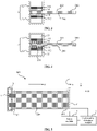
- FIG. 1 is a top view illustrating the structure of the testing apparatus for a flexible screen according to an embodiment of the present application.
- FIG. 2 is a top view illustrating the structure of the testing apparatus for a flexible screen according to an embodiment of the present application when performing the curl testing on the flexible screen.
- the testing apparatus 100 for a flexible screen provided in this embodiment of the present application includes the slide rail 1, the reel 2, the clamping module 3, and the drive module 4.
- the reel 2 is secured to an end of the slide rail 1 in the extension direction M of the slide rail 1.
- the axial direction N of the reel 2 is perpendicular to the extension direction M of the slide rail 1.
- the flexible screen 200 includes the first end 201 and the second end 202 that are disposed opposite to each other.
- the reel 2 is configured to secure the first end 201 of the flexible screen 200.
- the reel 2 is configured to rotate to drive the flexible screen 200 to fit snugly to the reel 2 and coil around the reel 2.
- the clamping module 3 is configured to clamp the second end 202 of the flexible screen 200.
- the reel 2 rotates to drive, through the flexible screen, the clamping module 3 to slide along the slide rail 1 towards the reel 2 200.
- FIG. 3 is a side view illustrating the structure of the clamping module of the testing apparatus for a flexible screen according to an embodiment of the present application.
- the clamping module 3 includes a first clamping module 32 and a second clamping module 33 that are disposed opposite to each other.
- the first clamping module 32 includes a first pressure sensing sub-module 311.
- the second clamping module 33 includes a second pressure sensing sub-module 312.
- the first pressure sensing sub-module 311 and the second pressure sensing sub-module 312 can be collectively referred to as the pressure sensing sub-module 31.
- the pressure sensing sub-module 31 is configured to detect the tension received by the flexible screen 200 in the extension direction M of the slide rail 1 and generate the tension detection signal.
- the drive module 4 adjusts the rotation angular velocity co of the reel 2 according to the tension detection signal received.
- the flexible screen 200 includes the first end 201 and the second end 202 that are disposed opposite to each other.
- the reel 2 of the testing apparatus 100 of the flexible screen 200 secures the first end 201 of the flexible screen 200.
- the clamping module 3 clamps the second end 202 of the flexible screen 200.
- the drive module 4 controls the rotation of the reel 2 to drive the flexible screen 200 to fit snugly to the reel and coil around the reel 2.
- the flexible screen 200 drives the clamping module 3 to slide along the slide rail 1 towards the reel 2. Since the clamping module 3 includes the pressure sensing sub-module 31, the pressure sensing sub-module 31 can detect the tension received by the flexible screen 200 in the extension direction M of the slide rail 1 during the curl testing of the flexible screen 200 by the testing apparatus 100 of the flexible screen 200.
- the tension detection signal is generated by the detected tension of the flexible screen 200.
- the tension detection signal can correspond to several situations: the tension is within a testing threshold range, the tension is greater than the testing threshold range, or the tension is less than the testing threshold range.
- the drive module 4 adjusts the angular velocity of the rotation of the reel 2 according to the received tension detection signal.
- the apparatus 100 can be disposed that when the tension corresponding to the tension detection signal received by the drive module 4 is within the testing threshold range, the drive module 4 maintains the rotation angular velocity co of the reel 2.
- the drive module 4 reduces the rotation angular velocity co of the reel 2.
- the drive module 4 increases the rotation angular velocity co of the reel 2.
- the tension of the flexible screen 200 in the extension direction M of the slide rail 1 is kept constant by the pressure sensing sub-module 31, so as to improve the stability of the flexible screen 200 during the coiling process, ensure the smooth coil testing of the flexible screen 200, and prevent the evaluation of the coli characteristic of the flexible screen 200 from being affected by the local bulging of the flexible screen 200.
- the first clamping module 32 and the second clamping module 33 are located on two sides of the clamped portion of the flexible screen 200.
- the clamping module 3 clamps two sides of the second end 202 of the flexible screen 200 through the first clamping module 32 and the second clamping module 33.
- the first pressure sensing sub-module 311 included in the first clamping module 32 is configured to detect the tension received by a side of the second end 202 of the flexible screen 200 facing the first clamping module 32 in the extension direction M of the slide rail 1, and generate a first tension detection signal.
- the second pressure sensing sub-module 312 included in the second clamping module 33 is configured to detect the tension received by a side of the second end 202 of the flexible screen 200 facing the second clamping module 33 in the extension direction M of the slide rail 1, and generate a second tension detection signal.
- the drive module 4 generates the tension detection signal according to the received first tension detection signal and the second tension detection signal.
- the drive module 4 adjusts the rotation angular velocity co of the reel 2 according to the tension detection signal.
- the tension detection signal includes the first tension detection signal and the second tension detection signal.
- the drive module 4 maintains the rotation angular velocity co of the reel 2.
- the drive module 4 reduces the rotation angular velocity co of the reel 2.
- the drive module 4 increases the rotation angular velocity co of the reel 2
- the first pressure sensing sub-module 311 of the first clamping module 32 and the second pressure sensing sub-module 312 of the second clamping module 33 improve the detection accuracy of the tension by the pressure sensing sub-module 31, better keep the tension of the flexible screen 200 in the extension direction M of the slide rail 1 constant during the curling process, improve the stability of the flexible screen 200 during the coiling process, ensure the smooth curl testing of the flexible screen 200, and improve the evaluation of the coil characteristic of the flexible screen 200.
- the first pressure sensing sub-module 311 and the second pressure sensing sub-module 312 each includes a resistance strain gauge.
- the resistance strain gauge can detect the tension received by the flexible screen 200 in the extension direction M of the slide rail 1, and convert the detected tension signal into an electrical signal to generate the tension detection signal.
- the resistance strain gauge included in the first pressure sensing sub-module 311 correspondingly generates the first tension detection signal.
- the resistance strain gauge included in the second pressure sensing sub-module 312 correspondingly generates the second tension detection signal.
- the first clamping module 32 and/or the second clamping module 33 include/includes a vacuum layer 34/vacuum adsorbent layers 34.
- the vacuum adsorbent layer 34 is disposed in contact with a corresponding surface of the flexible screen 200.
- the vacuum adsorbent layer 34 is configured to perform vacuum adsorption on the corresponding surface.
- the vacuum adsorbent layer 34 is located on a side of the corresponding pressure sensing sub-module 31 facing the flexible screen 200.
- the vacuum adsorbent layer 34 included in the first clamping module 32 is disposed in contact with the corresponding surface of the flexible screen 200.
- the corresponding surface of the flexible screen 200 can be an upper surface 203 of the flexible screen 200. Due to the presence of the vacuum adsorbent layer 34, the pressure on the corresponding surface of the flexible screen 200 disposed in contact with the vacuum adsorbent layer 34, that is, the upper surface 203 of the flexible screen 200, is really small and approximately zero.
- the flexible screen 200 is tightly adsorbed by the vacuum adsorbent layer 34 included in the first clamping module 32, so as to strengthen the force on the screen body of the flexible screen 200 and reduce the damage of the clamping module 3 to the contact position of the second end 202 of the flexible screen 200.
- the vacuum adsorbent layer 34 included in the second clamping module 33 is disposed in contact with a corresponding surface of the flexible screen 200.
- the corresponding surface of the flexible screen 200 can be a lower surface 204 of the flexible screen 200. Due to the presence of the vacuum adsorbent layer 34, the pressure on the corresponding surface of the flexible screen 200 disposed in contact with the vacuum adsorbent layer 34, that is, the lower surface 204 of the flexible screen 200, is really small and approximately zero.
- the flexible screen 200 is tightly adsorbed by the vacuum adsorbent layer 34 included in the second clamping module 33, so as to strengthen the force on the screen body of the flexible screen 200 and reduce the damage of the clamping module 3 to the contact position of the second end 202 of the flexible screen 200.
- the first clamping module 32 and the second clamping module 33 each includes a vacuum adsorbent layer 34. Due to the presence of the vacuum adsorbent layer 34 of the first clamping module 32 and the vacuum adsorbent layer 34 of the second clamping module 33, the pressures on the corresponding surfaces of the flexible screen 200 disposed in contact with the vacuum adsorbent layers 34. The upper surface and the lower surface 204 of the flexible screen 200 are really small and approximately zero.
- the flexible screen 200 is tightly adsorbed by the vacuum adsorbent layer 34 included in the first clamping module 32 and the vacuum adsorbent layer 34 included in the second clamping module 33, so as to strengthen the force on the screen body of the flexible screen 200 and reduce the damage of the clamping module 3 to the contact position of the second end 202 of the flexible screen 200.
- FIG. 3 illustrates the case where the first clamping module 32 and the second clamping module 33 each includes a vacuum adsorbent layer 34.
- FIG. 4 is another side view illustrating the structure of the clamping module of the testing apparatus for a flexible screen according to an embodiment of the present application.
- the first clamping module 32 and the second clamping module 33 each includes a vacuum adsorbent layer 34.
- the vacuum adsorbent layers 34 include a plurality of vacuum adsorbent holes 341 in contact with the corresponding surface.
- the vacuum adsorbent holes 341 in the first clamping module 32 and the vacuum adsorbent holes 341 in the second clamping module 33 are disposed in a one-to-one correspondence in a direction in which the first clamping module 32 and the second clamping module 33 are disposed opposite to each other.
- the vacuum adsorbent layers 34 include the plurality of vacuum adsorbent holes 341 in contact with the corresponding surface.
- the vacuum adsorbent holes 341 are evacuated.
- the vacuum adsorbent holes 341 in the first clamping module 32 and the vacuum adsorbent holes 341 in the second clamping module 33 are disposed in a one-to-one correspondence. Therefore the upper surface 203 and the lower surface 204 of the flexible screen 200 are adsorbed tightly through the vacuum adsorbent holes 341 disposed in a one-to-one correspondence, which improves the clamping ability of the clamping module 3 to the flexible screen 200 and strengthens the securing of the flexible screen 200.
- the uniformity of the force on the flexible screen 200 is improved, and the damage to the flexible screen 200 during the curl testing of the flexible screen 200 is reduced.
- the vacuum adsorbent layer 34 is a flexible material layer.
- the flexible material layer can serve a protective and cushioning function for the flexible screen 200.
- the vacuum adsorbent hole 341 is located on the flexible material layer. Therefore the second end 202 of the flexible screen 200 can be uniformly forced to prevent local bulging during the curling process.
- the flexible material layer can be such as silica gel, ethylene propylene diene monomer or the like.
- the first clamping module 32 and the second clamping module 33 each includes a resilient element 35.
- the two resilient elements 35 are disposed opposite to each other.
- the two resilient elements 35 are located on two sides of the clamped portion of the flexible screen 200.
- One resilient element 35 of the resilient elements 35 is located on a side of the corresponding pressure sensing sub-module 31 facing away from the flexible screen 200.
- the one resilient element 35 includes a spring.
- the resilient element 35 is located on a side of the corresponding pressure sensing sub-module 31 facing away from the flexible screen 200.
- the resilient element 35 is configured to secure the pressure sensing sub-module 31 to the clamping module 3.
- the flexible screen 200 is clamped and secured on the clamping module 3 by the resilient elements 35 located on two sides of the clamped portion of the flexible screen 200.
- the resilient element 35 includes the spring that has a certain resilientity.
- the testing apparatus can be disposed that when the spring is compressed, the first clamping module 32 and the second clamping module 33 of the clamping module 3 are conveniently opened.
- the flexible screen 200 is placed between the first clamping module 32 and the second clamping module 33. When the spring is extended, the first clamping module 32 and the second clamping module 33 of the clamping module 3 are conveniently closed.
- the flexible screen 200 is clamped between the first clamping module 32 and the second clamping module 33. Therefore, the flexible screen 200 is conveniently secured during the testing.
- the flexible screen 200 is conveniently separated from the clamping module
- FIG. 5 is another top view illustrating the structure of the testing apparatus for a flexible screen according to an embodiment of the present application.
- the testing apparatus also includes a coil number detection module 5 configured to detect the number of coils of the flexible screen 200 on the reel 2 and generate a coil number detection signal.
- the drive module 4 is also configured to adjust the rotation velocity ⁇ of the reel 2 according to the coil number detection signal received.
- the coil number detection module 5 detects the number of coils of the flexible screen 200 on the reel 2 and generates the coil number detection signal.
- the coil number detection signal includes the corresponding angular velocity matching signal of the reel 2 output according to a matching relationship between the number of coils and the coil radius of the flexible screen 200.
- the drive module 4 adjusts the angular velocity co of the rotation of the reel 2 according to the received coil number detection signal.
- R denotes the radius of the reel 2. co denotes the angular velocity of the reel 2. V denotes a horizontal moving velocity. d denotes the thickness of the flexible screen 200.
- the coil number detection module 5 detects the number of coils to cooperate with the drive module 4 to adjust the angular velocity of reel 2, so as to match the angular velocity of the rotation of the reel 2 with the number of coils of the flexible screen 200. Therefore the accuracy of the testing is ensured.
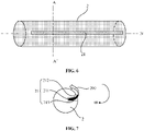
- FIG. 6 is a structure view of the reel of the testing apparatus for a flexible screen according to an embodiment of the present application.
- FIG. 7 is a structure view of a cross-section of the reel in the A-A' direction of the testing apparatus for a flexible screen according to an embodiment of the present application.
- the reel 2 is disposed with a slot 21.
- An extension direction of the slot 21 is parallel to the axial direction N of the reel 2.
- a surface 211 of the slot 21 adjacent to an axis of the reel 2 is configured to secure the first end 201 of the flexible screen 200.
- the reel 2 rotates to drive the flexible screen 200 to fit snugly to the reel 2 and coil around the reel 2 through the slot 21.
- the surface 211 of the slot 21 adjacent to the axis of the reel 2 secures the first end 201 of the flexible screen 200 in a pneumatic or a mechanical manner. Therefore the first end 201 of the flexible screen 200 is secured on the surface 211 adjacent to the axis of the reel 2 in the slot 21.
- the first end 201 of the flexible screen 200 is not easily slid out of the slot 21. Therefore the first end 201 of the flexible screen 200 is firmly secured in the slot 21 of the reel 2, so as to drive the flexible screen 200 to fit snugly around and coil around the reel 2 through the slot 21, thereby ensuring a smooth curling movement of the flexible screen 200.
- the slot 21 includes a first side wall 212 and a second side wall 213 sequentially disposed in a rotation direction of the reel 2.
- the first side wall 212 is bent in a direction opposite to the rotation direction of the reel 2.
- a curvature of the bent first side wall 212 is the same as a curvature of the reel 2.
- FIG. 7 the case that the rotation direction of the reel 2 is clockwise is illustrated.
- the first side wall 212 is bent in the direction opposite to the rotation direction of the reel 2, that is, the first side wall 212 bends in a counterclockwise direction.
- the first side wall 212 is bent in the direction opposite to the rotation direction of the reel 2. Therefore, when the reel 200 drives the flexible screen 200 to curl, the first end 201 of the flexible screen 200 that is close to the first side wall 212 bent in the direction opposite to the rotation direction of the reel 2 starts to curl, thereby reducing the problem that the initial position of the first end 201 of the flexible screen 200 is damaged due to excessive bending angle and uneven local force.
- the curvature of the bent first side wall 212 is the same as the curvature of the reel 2. Therefore the curling radius of the initial position of the first end 201 of the flexible screen 200 is large enough.
- the first end 201 of the flexible screen 200 at the slot 21 of the reel 200 can be effectively prevented from being damaged due to excessive bending angle and uneven local force on the flexible screen 200, thereby improving the accuracy of the curling performance evaluation of the flexible screen 200.
Landscapes
- Physics & Mathematics (AREA)
- General Physics & Mathematics (AREA)
- Chemical & Material Sciences (AREA)
- Analytical Chemistry (AREA)
- Health & Medical Sciences (AREA)
- Life Sciences & Earth Sciences (AREA)
- Biochemistry (AREA)
- General Health & Medical Sciences (AREA)
- Immunology (AREA)
- Pathology (AREA)
- Investigating Strength Of Materials By Application Of Mechanical Stress (AREA)
Abstract
Description
- This application claims priority to
Chinese Patent Application No. 202010027388.X filed with the CNIPA on January 10, 2020 - The present application relates to the field of display technology, for example, a testing apparatus for a flexible screen.
- With the development of display technology and the improvement of people's living standards, flexible screens are becoming the development trend of display screens in the future.
- However, when a testing device for evaluating the coiling performance of a flexible screen clamps the flexible screen, it is easy to cause uneven force at two ends of the screen and damage the flexible screen. Moreover, during a coil testing, the testing device tends to cause locally uneven force of the screen body of the flexible screen, resulting in local bulging and deformation of the screen body. Furthermore, during the coil testing, the screen body of the flexible screen bends at a large angle at the reel at the initial coiling stage, resulting in uneven force. Consequently, the problem of a large error in evaluating the coiling characteristic of the screen body of the flexible screen occurs in the testing device.
- The present application provides a testing apparatus for a flexible screen to alleviate the problem of a large error in evaluating the curl characteristic of the screen body of the flexible screen.
- An embodiment of the present application provides a testing apparatus for a flexible screen. The apparatus includes a slide rail, a reel, a clamping module and a drive module.
- The testing apparatus for a flexible screen includes a reel. The reel is secured to an end of the slide rail. An axial direction of the reel is perpendicular to an extension direction of the slide rail. The flexible screen includes a first end and a second end that are disposed opposite to each other.
- The reel is configured to secure the first end of the flexible screen and rotate to drive the flexible screen to fit snugly to the reel and coil around the reel.
- The testing apparatus for a flexible screen includes a clamping module. The clamping module is configured to clamp the second end of the flexible screen. The reel is further configured to rotate to drive, through the flexible screen, the clamping module to slide along the slide rail towards the reel. The clamping module includes a pressure sensing sub-module. The pressure sensing sub-modules are configured to detect tension received by the flexible screen in the extension direction of the slide rail and generate a tension detection signal.
- The testing apparatus for a flexible screen includes a drive module. The drive module adjusts a rotation angular velocity the reel according to the received tension detection signal.
- The testing apparatus for a flexible screen provided in the embodiment of the present application includes the slide rail, the reel, the clamping module and the drive module. The reel is secured to an end of the slide rail in the extension direction of the slide rail. The axial direction of the reel is perpendicular to the extension direction of the slide rail. The flexible screen includes the first end and the second end that are disposed opposite to each other. The reel is configured to secure the first end of the flexible screen. The reel is configured to rotate to drive the flexible screen to fit snugly to the reel and coil around the reel. The clamping module is configured to clamp the second end of the flexible screen. The reel rotates to drive, through the flexible screen, the clamping module to slide along the slide rail towards the reel. The clamping module includes pressure sensing sub-modules. The pressure sensing sub-module is configured to detect the tension received by the flexible screen in the extension direction of the slide rail and generate the tension detection signal. The drive module adjusts the rotation angular velocity of the reel according to the received tension detection signal. In the testing apparatus for a flexible screen according to the embodiment of the present application, the clamping module includes the pressure sensing sub-module configured to detect the tension received by the flexible screen in the extension direction of the slide rail and generate the tension detection signal and the drive module is configured to adjust the rotation angular velocity of the reel according to the received tension detection signal. In this manner, the problem of a large error in evaluating the curl characteristic of the screen body of the flexible screen is alleviated.
-
-
FIG. 1 is a top view illustrating the structure of a testing apparatus for a flexible screen according to an embodiment of the present application. -
FIG. 2 is a top view illustrating the structure of a testing apparatus for a flexible screen according to an embodiment of the present application when the apparatus performs a coil testing on the flexible screen. -
FIG. 3 is a side view illustrating the structure of the clamping module of a testing apparatus for a flexible screen according to an embodiment of the present application. -
FIG. 4 is another side view illustrating the structure of the clamping module of a testing apparatus for a flexible screen according to an embodiment of the present application. -
FIG. 5 is another top view illustrating the structure of a testing apparatus for a flexible screen according to an embodiment of the present application. -
FIG. 6 is a schematic view illustrating the structure of the reel of a testing apparatus for a flexible screen according to an embodiment of the present application. -
FIG. 7 is a section view taken along A-A' to illustrate the structure of the reel of a testing apparatus for a flexible screen according to an embodiment of the present application. - The present application is described hereinafter in conjunction with drawings and embodiments. The embodiments described herein are merely intended to explain, and not to limit, the present application. For ease of description, only part, not all, of the structures related to the present application are illustrated in the drawings.
- When the testing device for evaluating the coiling performance of the flexible screen clamps the flexible screen, it is easy to cause uneven force at two ends of the screen and damage the flexible screen. During the coil testing, the testing device is also easy to cause locally uneven force of the screen body of the flexible screen, resulting in the local bulging and deformation of the screen body. Moreover, the testing device is also easy to cause the screen body of the flexible screen to bend at a large angle at the reel at the initial coil stage, resulting in uneven force. Therefore, the testing device has the problem of large error in evaluating the coil characteristic of the screen body of the flexible screen.
- The embodiment below proposes a structure of the testing apparatus for a flexible screen, which can solve the preceding problems.
-
FIG. 1 is a top view illustrating the structure of the testing apparatus for a flexible screen according to an embodiment of the present application.FIG. 2 is a top view illustrating the structure of the testing apparatus for a flexible screen according to an embodiment of the present application when performing the curl testing on the flexible screen. Referring toFIG. 1 and FIG. 2 , thetesting apparatus 100 for a flexible screen provided in this embodiment of the present application includes theslide rail 1, thereel 2, theclamping module 3, and the drive module 4. Thereel 2 is secured to an end of theslide rail 1 in the extension direction M of theslide rail 1. The axial direction N of thereel 2 is perpendicular to the extension direction M of theslide rail 1. Theflexible screen 200 includes thefirst end 201 and thesecond end 202 that are disposed opposite to each other. Thereel 2 is configured to secure thefirst end 201 of theflexible screen 200. Thereel 2 is configured to rotate to drive theflexible screen 200 to fit snugly to thereel 2 and coil around thereel 2. Theclamping module 3 is configured to clamp thesecond end 202 of theflexible screen 200. Thereel 2 rotates to drive, through the flexible screen, theclamping module 3 to slide along theslide rail 1 towards thereel 2 200.FIG. 3 is a side view illustrating the structure of the clamping module of the testing apparatus for a flexible screen according to an embodiment of the present application. Referring toFIG. 3 , theclamping module 3 includes afirst clamping module 32 and asecond clamping module 33 that are disposed opposite to each other. Thefirst clamping module 32 includes a firstpressure sensing sub-module 311. Thesecond clamping module 33 includes a second pressure sensing sub-module 312. The first pressure sensing sub-module 311 and the second pressure sensing sub-module 312 can be collectively referred to as thepressure sensing sub-module 31. Thepressure sensing sub-module 31 is configured to detect the tension received by theflexible screen 200 in the extension direction M of theslide rail 1 and generate the tension detection signal. The drive module 4 adjusts the rotation angular velocity co of thereel 2 according to the tension detection signal received. - The
flexible screen 200 includes thefirst end 201 and thesecond end 202 that are disposed opposite to each other. Thereel 2 of thetesting apparatus 100 of theflexible screen 200 secures thefirst end 201 of theflexible screen 200. Theclamping module 3 clamps thesecond end 202 of theflexible screen 200. The drive module 4 controls the rotation of thereel 2 to drive theflexible screen 200 to fit snugly to the reel and coil around thereel 2. At the same time, theflexible screen 200 drives theclamping module 3 to slide along theslide rail 1 towards thereel 2. Since theclamping module 3 includes thepressure sensing sub-module 31, the pressure sensing sub-module 31 can detect the tension received by theflexible screen 200 in the extension direction M of theslide rail 1 during the curl testing of theflexible screen 200 by thetesting apparatus 100 of theflexible screen 200. The tension detection signal is generated by the detected tension of theflexible screen 200. The tension detection signal can correspond to several situations: the tension is within a testing threshold range, the tension is greater than the testing threshold range, or the tension is less than the testing threshold range. The drive module 4 adjusts the angular velocity of the rotation of thereel 2 according to the received tension detection signal. - Exemplarily, the
apparatus 100 can be disposed that when the tension corresponding to the tension detection signal received by the drive module 4 is within the testing threshold range, the drive module 4 maintains the rotation angular velocity co of thereel 2. When the tension corresponding to the tension detection signal received by the drive module 4 is greater than a maximum value of the testing threshold range, the drive module 4 reduces the rotation angular velocity co of thereel 2. When the tension corresponding to the tension detection signal received by the drive module 4 is less than a minimum value of the testing threshold range, the drive module 4 increases the rotation angular velocity co of thereel 2. During a coiling process, the tension of theflexible screen 200 in the extension direction M of theslide rail 1 is kept constant by thepressure sensing sub-module 31, so as to improve the stability of theflexible screen 200 during the coiling process, ensure the smooth coil testing of theflexible screen 200, and prevent the evaluation of the coli characteristic of theflexible screen 200 from being affected by the local bulging of theflexible screen 200. - Optionally, referring to
FIG. 3 , thefirst clamping module 32 and thesecond clamping module 33 are located on two sides of the clamped portion of theflexible screen 200. - The
clamping module 3 clamps two sides of thesecond end 202 of theflexible screen 200 through thefirst clamping module 32 and thesecond clamping module 33. The first pressure sensing sub-module 311 included in thefirst clamping module 32 is configured to detect the tension received by a side of thesecond end 202 of theflexible screen 200 facing thefirst clamping module 32 in the extension direction M of theslide rail 1, and generate a first tension detection signal. The second pressure sensing sub-module 312 included in thesecond clamping module 33 is configured to detect the tension received by a side of thesecond end 202 of theflexible screen 200 facing thesecond clamping module 33 in the extension direction M of theslide rail 1, and generate a second tension detection signal. The drive module 4 generates the tension detection signal according to the received first tension detection signal and the second tension detection signal. The drive module 4 adjusts the rotation angular velocity co of thereel 2 according to the tension detection signal. - The tension detection signal includes the first tension detection signal and the second tension detection signal. When the tension corresponding to the first tension detection signal and the tension corresponding to the second tension detection signal received by the drive module 4 each are within the testing threshold range, the drive module 4 maintains the rotation angular velocity co of the
reel 2. When the tension corresponding to the first tension detection signal and/or the tension corresponding to the second tension detection signal received by the drive module 4 are/is greater than the maximum value of the testing threshold range, the drive module 4 reduces the rotation angular velocity co of thereel 2. When the tension corresponding to the first tension detection signal and/or the tension corresponding to the second tension detection signal received by the drive module 4 are/is less than the minimum value of the testing threshold range, the drive module 4 increases the rotation angular velocity co of thereel 2 - The first
pressure sensing sub-module 311 of thefirst clamping module 32 and the secondpressure sensing sub-module 312 of thesecond clamping module 33 improve the detection accuracy of the tension by thepressure sensing sub-module 31, better keep the tension of theflexible screen 200 in the extension direction M of theslide rail 1 constant during the curling process, improve the stability of theflexible screen 200 during the coiling process, ensure the smooth curl testing of theflexible screen 200, and improve the evaluation of the coil characteristic of theflexible screen 200. - Optionally, the first pressure sensing sub-module 311 and the second pressure sensing sub-module 312 each includes a resistance strain gauge. The resistance strain gauge can detect the tension received by the
flexible screen 200 in the extension direction M of theslide rail 1, and convert the detected tension signal into an electrical signal to generate the tension detection signal. The resistance strain gauge included in the first pressure sensing sub-module 311 correspondingly generates the first tension detection signal. The resistance strain gauge included in the second pressure sensing sub-module 312 correspondingly generates the second tension detection signal. - Optionally, referring to
FIG. 3 , thefirst clamping module 32 and/or thesecond clamping module 33 include/includes avacuum layer 34/vacuum adsorbent layers 34. Thevacuum adsorbent layer 34 is disposed in contact with a corresponding surface of theflexible screen 200. Thevacuum adsorbent layer 34 is configured to perform vacuum adsorption on the corresponding surface. Thevacuum adsorbent layer 34 is located on a side of the corresponding pressure sensing sub-module 31 facing theflexible screen 200. - The
vacuum adsorbent layer 34 included in thefirst clamping module 32 is disposed in contact with the corresponding surface of theflexible screen 200. The corresponding surface of theflexible screen 200 can be anupper surface 203 of theflexible screen 200. Due to the presence of thevacuum adsorbent layer 34, the pressure on the corresponding surface of theflexible screen 200 disposed in contact with thevacuum adsorbent layer 34, that is, theupper surface 203 of theflexible screen 200, is really small and approximately zero. Theflexible screen 200 is tightly adsorbed by thevacuum adsorbent layer 34 included in thefirst clamping module 32, so as to strengthen the force on the screen body of theflexible screen 200 and reduce the damage of theclamping module 3 to the contact position of thesecond end 202 of theflexible screen 200. - Alternatively, the
vacuum adsorbent layer 34 included in thesecond clamping module 33 is disposed in contact with a corresponding surface of theflexible screen 200. The corresponding surface of theflexible screen 200 can be alower surface 204 of theflexible screen 200. Due to the presence of thevacuum adsorbent layer 34, the pressure on the corresponding surface of theflexible screen 200 disposed in contact with thevacuum adsorbent layer 34, that is, thelower surface 204 of theflexible screen 200, is really small and approximately zero. Theflexible screen 200 is tightly adsorbed by thevacuum adsorbent layer 34 included in thesecond clamping module 33, so as to strengthen the force on the screen body of theflexible screen 200 and reduce the damage of theclamping module 3 to the contact position of thesecond end 202 of theflexible screen 200. - Alternatively, the
first clamping module 32 and thesecond clamping module 33 each includes avacuum adsorbent layer 34. Due to the presence of thevacuum adsorbent layer 34 of thefirst clamping module 32 and thevacuum adsorbent layer 34 of thesecond clamping module 33, the pressures on the corresponding surfaces of theflexible screen 200 disposed in contact with the vacuum adsorbent layers 34. The upper surface and thelower surface 204 of theflexible screen 200 are really small and approximately zero. Theflexible screen 200 is tightly adsorbed by thevacuum adsorbent layer 34 included in thefirst clamping module 32 and thevacuum adsorbent layer 34 included in thesecond clamping module 33, so as to strengthen the force on the screen body of theflexible screen 200 and reduce the damage of theclamping module 3 to the contact position of thesecond end 202 of theflexible screen 200.FIG. 3 illustrates the case where thefirst clamping module 32 and thesecond clamping module 33 each includes avacuum adsorbent layer 34. - Optionally,
FIG. 4 is another side view illustrating the structure of the clamping module of the testing apparatus for a flexible screen according to an embodiment of the present application. Referring toFIG. 4 , thefirst clamping module 32 and thesecond clamping module 33 each includes avacuum adsorbent layer 34. The vacuum adsorbent layers 34 include a plurality of vacuumadsorbent holes 341 in contact with the corresponding surface. The vacuum adsorbent holes 341 in thefirst clamping module 32 and the vacuum adsorbent holes 341 in thesecond clamping module 33 are disposed in a one-to-one correspondence in a direction in which thefirst clamping module 32 and thesecond clamping module 33 are disposed opposite to each other. - The vacuum adsorbent layers 34 include the plurality of vacuum
adsorbent holes 341 in contact with the corresponding surface. The vacuum adsorbent holes 341 are evacuated. The vacuum adsorbent holes 341 in thefirst clamping module 32 and the vacuum adsorbent holes 341 in thesecond clamping module 33 are disposed in a one-to-one correspondence. Therefore theupper surface 203 and thelower surface 204 of theflexible screen 200 are adsorbed tightly through the vacuum adsorbent holes 341 disposed in a one-to-one correspondence, which improves the clamping ability of theclamping module 3 to theflexible screen 200 and strengthens the securing of theflexible screen 200. Moreover, with the arrangement in which the vacuum adsorbent holes 341 in thefirst clamping module 32 and the vacuum adsorbent holes 341 in thesecond clamping module 33 are disposed in a one-to-one correspondence, the uniformity of the force on theflexible screen 200 is improved, and the damage to theflexible screen 200 during the curl testing of theflexible screen 200 is reduced. - Optionally, the
vacuum adsorbent layer 34 is a flexible material layer. When theclamping module 3 of theflexible screen 200 secures theflexible screen 200, the flexible material layer can serve a protective and cushioning function for theflexible screen 200. Thevacuum adsorbent hole 341 is located on the flexible material layer. Therefore thesecond end 202 of theflexible screen 200 can be uniformly forced to prevent local bulging during the curling process. - The flexible material layer can be such as silica gel, ethylene propylene diene monomer or the like.
- Optionally, referring to
FIG. 4 , thefirst clamping module 32 and thesecond clamping module 33 each includes aresilient element 35. The tworesilient elements 35 are disposed opposite to each other. The tworesilient elements 35 are located on two sides of the clamped portion of theflexible screen 200. Oneresilient element 35 of theresilient elements 35 is located on a side of the corresponding pressure sensing sub-module 31 facing away from theflexible screen 200. For example, the oneresilient element 35 includes a spring. - The
resilient element 35 is located on a side of the corresponding pressure sensing sub-module 31 facing away from theflexible screen 200. Theresilient element 35 is configured to secure the pressure sensing sub-module 31 to theclamping module 3. Theflexible screen 200 is clamped and secured on theclamping module 3 by theresilient elements 35 located on two sides of the clamped portion of theflexible screen 200. Theresilient element 35 includes the spring that has a certain resilientity. The testing apparatus can be disposed that when the spring is compressed, thefirst clamping module 32 and thesecond clamping module 33 of theclamping module 3 are conveniently opened. Theflexible screen 200 is placed between thefirst clamping module 32 and thesecond clamping module 33. When the spring is extended, thefirst clamping module 32 and thesecond clamping module 33 of theclamping module 3 are conveniently closed. Theflexible screen 200 is clamped between thefirst clamping module 32 and thesecond clamping module 33. Therefore, theflexible screen 200 is conveniently secured during the testing. Theflexible screen 200 is conveniently separated from theclamping module 3 at the end of the testing. - Optionally,
FIG. 5 is another top view illustrating the structure of the testing apparatus for a flexible screen according to an embodiment of the present application. Referring toFIG. 5 , the testing apparatus also includes a coilnumber detection module 5 configured to detect the number of coils of theflexible screen 200 on thereel 2 and generate a coil number detection signal. The drive module 4 is also configured to adjust the rotation velocity ω of thereel 2 according to the coil number detection signal received. - As the number of coils of the
flexible screen 200 on thereel 2 increases, a coil radius of theflexible screen 200 will increase. The coilnumber detection module 5 detects the number of coils of theflexible screen 200 on thereel 2 and generates the coil number detection signal. The coil number detection signal includes the corresponding angular velocity matching signal of thereel 2 output according to a matching relationship between the number of coils and the coil radius of theflexible screen 200. Moreover, the drive module 4 adjusts the angular velocity co of the rotation of thereel 2 according to the received coil number detection signal. Exemplarily, the number of coils is the first coil: co = V/R; the number of coils is the second coil 2πR: co = V/(R+d); the number of coils is the third coil 2πR + 2π (R + d): co = V/(R+2d), .... - R denotes the radius of the
reel 2. co denotes the angular velocity of thereel 2. V denotes a horizontal moving velocity. d denotes the thickness of theflexible screen 200. The coilnumber detection module 5 detects the number of coils to cooperate with the drive module 4 to adjust the angular velocity ofreel 2, so as to match the angular velocity of the rotation of thereel 2 with the number of coils of theflexible screen 200. Therefore the accuracy of the testing is ensured. - Optionally,
FIG. 6 is a structure view of the reel of the testing apparatus for a flexible screen according to an embodiment of the present application.FIG. 7 is a structure view of a cross-section of the reel in the A-A' direction of the testing apparatus for a flexible screen according to an embodiment of the present application. In conjunction withFIG. 6 and FIG. 7 , thereel 2 is disposed with aslot 21. An extension direction of theslot 21 is parallel to the axial direction N of thereel 2. Asurface 211 of theslot 21 adjacent to an axis of thereel 2 is configured to secure thefirst end 201 of theflexible screen 200. Thereel 2 rotates to drive theflexible screen 200 to fit snugly to thereel 2 and coil around thereel 2 through theslot 21. - The
surface 211 of theslot 21 adjacent to the axis of thereel 2 secures thefirst end 201 of theflexible screen 200 in a pneumatic or a mechanical manner. Therefore thefirst end 201 of theflexible screen 200 is secured on thesurface 211 adjacent to the axis of thereel 2 in theslot 21. When thereel 2 rotates, thefirst end 201 of theflexible screen 200 is not easily slid out of theslot 21. Therefore thefirst end 201 of theflexible screen 200 is firmly secured in theslot 21 of thereel 2, so as to drive theflexible screen 200 to fit snugly around and coil around thereel 2 through theslot 21, thereby ensuring a smooth curling movement of theflexible screen 200. - Optionally, referring to
FIG. 7 , theslot 21 includes afirst side wall 212 and asecond side wall 213 sequentially disposed in a rotation direction of thereel 2. Thefirst side wall 212 is bent in a direction opposite to the rotation direction of thereel 2. A curvature of the bentfirst side wall 212 is the same as a curvature of thereel 2. InFIG. 7 , the case that the rotation direction of thereel 2 is clockwise is illustrated. Thefirst side wall 212 is bent in the direction opposite to the rotation direction of thereel 2, that is, thefirst side wall 212 bends in a counterclockwise direction. - The
first side wall 212 is bent in the direction opposite to the rotation direction of thereel 2. Therefore, when thereel 200 drives theflexible screen 200 to curl, thefirst end 201 of theflexible screen 200 that is close to thefirst side wall 212 bent in the direction opposite to the rotation direction of thereel 2 starts to curl, thereby reducing the problem that the initial position of thefirst end 201 of theflexible screen 200 is damaged due to excessive bending angle and uneven local force. - The curvature of the bent
first side wall 212 is the same as the curvature of thereel 2. Therefore the curling radius of the initial position of thefirst end 201 of theflexible screen 200 is large enough. Thefirst end 201 of theflexible screen 200 at theslot 21 of thereel 200 can be effectively prevented from being damaged due to excessive bending angle and uneven local force on theflexible screen 200, thereby improving the accuracy of the curling performance evaluation of theflexible screen 200.
Claims (18)
- A testing apparatus for a flexible screen, characterized by comprising:a slide rail;a reel, secured to an end of the slide rail, an axial direction of the reel is perpendicular to an extension direction of the slide rail, the flexible screen comprising a first end and a second end disposed opposite to each other, and the reel being configured to secure the first end of the flexible screen and rotate to drive the flexible screen to fit to the reel and coil around the reel;a clamping module, configured to clamp the second end of the flexible screen, the reel being further configured to rotate to drive, through the flexible screen, the clamping module to slide along the slide rail in a direction towards the reel, and the clamping module comprising a pressure sensing sub-module, wherein the pressure sensing sub-module is configured to detect tension received by the flexible screen in the extension direction of the slide rail and generate a tension detection signal; anda drive module, configured to adjust an rotation angular velocity of the reel according to a tension detection signal received.
- The apparatus of claim 1, wherein the clamping module comprises a first clamping module and a second clamping module disposed opposite to each other, wherein the first clamping module and the second clamping module are located on two sides of a clamped portion of the flexible screen; and
the pressure sensing sub-module comprises a first pressure sensing sub-module and a second pressure sensing sub-module, wherein the first pressure sensing sub-module is disposed in the first clamping module, and the second pressure sensing sub-module is disposed in the second clamping module. - The apparatus of claim 2, wherein the first pressure sensing sub-module and the second pressure sensing sub-module respectively comprises a resistance strain gauge.
- The apparatus of claim 2 or 3, wherein at least one of the first clamping module or the second clamping module comprises a vacuum adsorbent layer, wherein the vacuum adsorbent layer is located on a side of a corresponding pressure sensing sub-module facing to the flexible screen, the vacuum adsorbent layer is disposed in contact with a corresponding surface of the flexible screen, and the vacuum adsorbent layer is configured to perform vacuum adsorption on the corresponding surface.
- The apparatus of claim 4, wherein the first clamping module and the second clamping module respectively comprises the vacuum adsorbent layer, wherein the vacuum adsorbent layer comprises a plurality of vacuum adsorbent holes in contact with the corresponding surface of the flexible screen, and a plurality of vacuum adsorbent holes in the first clamping module and a plurality of vacuum adsorbent holes in the second clamping module are disposed in a one-to-one correspondence in a direction in which the first clamping module and the second clamping module are disposed opposite to each other.
- The apparatus of claim 4, wherein the vacuum adsorbent layer is a flexible material layer.
- The apparatus of claim 2 or 3, wherein the first clamping module and the second clamping module respectively comprises a resilient element, wherein a resilient element of the first clamping module and a resilient element of the second clamping module are disposed opposite to each other and are respectively located on a side of the a corresponding pressure sensing sub-module facing away from the flexible screen.
- The apparatus of claim 1, further comprising:a coil number detection module configured to detect a number of coils of the flexible screen on the reel and generate a coil number detection signal,wherein the drive module is further configured to adjust the rotation angular velocity of the reel according to a coil number detection signal received.
- The apparatus of claim 1, wherein the reel is provided with a slot, wherein an extension direction of the slot is parallel to the axial direction of the reel, a surface of the slot adjacent to an axis of the reel is configured to secure the first end of the flexible screen, and the reel is configured to rotate to drive the flexible screen to fit snugly to the reel and coil around the reel.
- The apparatus of claim 9, wherein the slot comprises a first side wall and a second side wall that are sequentially disposed in a rotation direction of the reel, wherein the first side wall is bent in a direction opposite to the rotation direction of the reel.
- The apparatus of claim 1, wherein the drive module is configured to:maintain the rotation angular velocity of the reel in a case where tension corresponding to the tension detection signal is within a testing threshold range;reduce the rotation angular velocity of the reel in a case where tension corresponding to the tension detection signal is greater than a maximum value of the testing threshold range; and increase the rotation angular velocity of the reel in a case where tension corresponding to the tension detection signal is less than a minimum value of the testing threshold range.
- The apparatus of claim 2, whereinthe first pressure sensing sub-module is configured to detect tension received by a side of the second end of the flexible screen facing the first clamping module in the extension direction of the slide rail and generate a first tension detection signal;the second pressure sensing sub-module is configured to detect tension received by a side of the second end of the flexible screen facing the second clamping module in the extension direction of the slide rail and generate a second tension detection signal; andthe drive module is configured to adjust the rotation angular velocity the reel according to a first tension detection signal received and a second tension detection signal received.
- The apparatus of claim 12, wherein the drive module is configured to:maintain the rotation angular velocity of the reel in a case where tension corresponding to the first tension detection signal and tension corresponding to the second tension detection signal are within a testing threshold range;reduce the rotation angular velocity of the reel in a case where at least one of tension corresponding to the first tension detection signal or tension corresponding to the second tension detection signal is greater than a maximum value of the testing threshold range; andincrease the rotation angular velocity of the reel in a case where at least one of tension corresponding to the first tension detection signal or tension corresponding to the second tension detection signal is less than a minimum value of the testing threshold range.
- The apparatus of claim 6, wherein the flexible material layer is made of silica gel or ethylene propylene diene monomer.
- The apparatus of claim 7, wherein the one resilient element comprises a spring.
- The apparatus of claim 8, wherein the coil number detection signal is an angular velocity matching signal of the reel obtained according to a matching relationship between the number of coils of the flexible screen and a coil radius of the flexible screen.
- The apparatus of claim 9, wherein the first end of the flexible screen is secured in a pneumatic manner or in a mechanical manner.
- The apparatus of claim 10, wherein a curvature of the first side wall bent is the same as a curvature of the reel.
Applications Claiming Priority (2)
| Application Number | Priority Date | Filing Date | Title |
|---|---|---|---|
| CN202010027388.XA CN111122132B (en) | 2020-01-10 | 2020-01-10 | Flexible screen testing device |
| PCT/CN2020/128086 WO2021139393A1 (en) | 2020-01-10 | 2020-11-11 | Testing device for flexible screen |
Publications (2)
| Publication Number | Publication Date |
|---|---|
| EP4016038A1 true EP4016038A1 (en) | 2022-06-22 |
| EP4016038A4 EP4016038A4 (en) | 2022-12-14 |
Family
ID=70487833
Family Applications (1)
| Application Number | Title | Priority Date | Filing Date |
|---|---|---|---|
| EP20912181.3A Pending EP4016038A4 (en) | 2020-01-10 | 2020-11-11 | TESTING DEVICE FOR A FLEXIBLE SCREEN |
Country Status (6)
| Country | Link |
|---|---|
| US (1) | US11828675B2 (en) |
| EP (1) | EP4016038A4 (en) |
| JP (1) | JP7268247B2 (en) |
| KR (1) | KR102742743B1 (en) |
| CN (1) | CN111122132B (en) |
| WO (1) | WO2021139393A1 (en) |
Families Citing this family (10)
| Publication number | Priority date | Publication date | Assignee | Title |
|---|---|---|---|---|
| CN111122132B (en) * | 2020-01-10 | 2022-04-15 | 昆山国显光电有限公司 | Flexible screen testing device |
| CN111583802B (en) * | 2020-05-22 | 2022-03-22 | 合肥维信诺科技有限公司 | Flexible display device |
| CN111627336B (en) * | 2020-06-09 | 2022-03-08 | 深圳创维-Rgb电子有限公司 | Display device |
| CN111624095B (en) * | 2020-07-08 | 2023-06-27 | 玛尔斯检测技术(苏州)有限公司 | Curl test platform and curl test method for double-motor flexible material |
| CN111624096B (en) * | 2020-07-08 | 2023-06-27 | 玛尔斯检测技术(苏州)有限公司 | Flexible material testing device and method |
| CN111624094B (en) * | 2020-07-08 | 2023-06-27 | 玛尔斯检测技术(苏州)有限公司 | Flexible material curling test platform and method |
| CN112722932B (en) * | 2020-12-01 | 2022-09-06 | 合肥维信诺科技有限公司 | Crimping device of flexible display panel |
| CN114112735A (en) * | 2021-12-06 | 2022-03-01 | 天津工业大学 | Fabric preform winding deformation testing device and method |
| CN116399701B (en) * | 2023-06-08 | 2023-08-04 | 常州佳尔科仿真器材有限公司 | Disguise net production is with damaged detection test device |
| KR102705808B1 (en) * | 2023-07-24 | 2024-09-12 | (재)한국건설생활환경시험연구원 | Transverse displacement test apparatus for external thermal insulation composite systems |
Family Cites Families (25)
| Publication number | Priority date | Publication date | Assignee | Title |
|---|---|---|---|---|
| JP4180484B2 (en) * | 2003-10-20 | 2008-11-12 | ダイセル化学工業株式会社 | High speed tensile test method |
| CN102645378B (en) | 2012-04-24 | 2015-06-03 | 华南理工大学 | Single drum type mechanical property stretching test method and device for plastic film |
| KR102124403B1 (en) * | 2013-08-02 | 2020-06-19 | 삼성디스플레이 주식회사 | Test apparatus of flexible device |
| CN203629786U (en) | 2013-12-18 | 2014-06-04 | 昆山工研院新型平板显示技术中心有限公司 | Testing device used for flexible screen |
| CN204330366U (en) | 2014-11-27 | 2015-05-13 | 昆山国显光电有限公司 | Flexible display screen RTA reliability test assembly |
| US9726587B2 (en) * | 2015-01-30 | 2017-08-08 | Stmicroelectronics S.R.L. | Tensile stress measurement device with attachment plates and related methods |
| CN106918733B (en) * | 2015-12-24 | 2019-10-11 | 昆山工研院新型平板显示技术中心有限公司 | Flexible reliability test fixture and flexible reliability on-line testing equipment |
| KR102482330B1 (en) * | 2016-04-26 | 2022-12-29 | 삼성디스플레이 주식회사 | Flexible display device and method for compensating image of flexible display device |
| KR101680875B1 (en) | 2016-05-20 | 2016-11-29 | 주식회사 지엔티시스템즈 | Bending and rolling examination apparatus for flexible display and bending and rolling examination method using this |
| CN106157816B (en) * | 2016-07-08 | 2017-11-17 | 广东欧珀移动通信有限公司 | A kind of flexible display apparatus |
| CN107993573A (en) * | 2016-10-27 | 2018-05-04 | 上海和辉光电有限公司 | Flexible display and its display methods |
| KR20180057897A (en) * | 2016-11-23 | 2018-05-31 | 삼성전자주식회사 | Evaluating device of flexural property of material, and evaluation method using thereof |
| KR101961222B1 (en) * | 2017-07-06 | 2019-03-22 | (주)에이엔에이치 | Characteristic evaluating apparatus for flexible display |
| CN207263446U (en) * | 2017-07-24 | 2018-04-20 | 昆山国显光电有限公司 | For detecting the device of flexible product service life |
| CN111051849A (en) * | 2017-07-31 | 2020-04-21 | 陶氏环球技术有限责任公司 | System for analyzing impact and puncture resistance |
| CN207133130U (en) * | 2017-08-09 | 2018-03-23 | 张啟来 | A kind of textile pull force calculation equipment |
| CN107860561B (en) * | 2017-11-09 | 2022-07-12 | 中国计量大学 | Flexible display screen bending characteristic measuring device |
| CN108225938B (en) * | 2018-01-31 | 2020-09-25 | 北京京东方显示技术有限公司 | Bending test device and bending test method |
| CN109388193A (en) * | 2018-10-18 | 2019-02-26 | 维沃移动通信有限公司 | A kind of acquisition methods and electronic equipment of flexible display screen spread length |
| CN109520714B (en) * | 2018-11-13 | 2020-11-20 | 京东方科技集团股份有限公司 | Curling equipment and flexible screen curling device |
| CN109743421B (en) * | 2018-12-29 | 2021-04-23 | Oppo广东移动通信有限公司 | Electronic device |
| CN209342509U (en) * | 2019-01-18 | 2019-09-03 | 云谷(固安)科技有限公司 | A kind of fixture and test device for flexible device test |
| CN209416663U (en) | 2019-03-12 | 2019-09-20 | 上海和辉光电有限公司 | A kind of flexible screen bending clamp |
| CN110118697A (en) * | 2019-05-16 | 2019-08-13 | 云谷(固安)科技有限公司 | Flexible screen body test device and its test method |
| CN111122132B (en) * | 2020-01-10 | 2022-04-15 | 昆山国显光电有限公司 | Flexible screen testing device |
-
2020
- 2020-01-10 CN CN202010027388.XA patent/CN111122132B/en active Active
- 2020-11-11 WO PCT/CN2020/128086 patent/WO2021139393A1/en not_active Ceased
- 2020-11-11 JP JP2022517322A patent/JP7268247B2/en active Active
- 2020-11-11 EP EP20912181.3A patent/EP4016038A4/en active Pending
- 2020-11-11 KR KR1020227008605A patent/KR102742743B1/en active Active
-
2022
- 2022-02-09 US US17/667,971 patent/US11828675B2/en active Active
Also Published As
| Publication number | Publication date |
|---|---|
| KR20220045034A (en) | 2022-04-12 |
| JP7268247B2 (en) | 2023-05-02 |
| JP2022549135A (en) | 2022-11-24 |
| KR102742743B1 (en) | 2024-12-12 |
| EP4016038A4 (en) | 2022-12-14 |
| CN111122132A (en) | 2020-05-08 |
| US11828675B2 (en) | 2023-11-28 |
| US20220170814A1 (en) | 2022-06-02 |
| WO2021139393A1 (en) | 2021-07-15 |
| CN111122132B (en) | 2022-04-15 |
Similar Documents
| Publication | Publication Date | Title |
|---|---|---|
| US11828675B2 (en) | Testing device for flexible screen | |
| US20220163433A1 (en) | Test apparatus for flexible screen | |
| US20170199547A1 (en) | Display apparatus and method for manufacturing the same | |
| US20220276675A1 (en) | Flexible screen support device and flexible display terminal | |
| WO2021238433A1 (en) | Terminal provided with flexible screen | |
| US11474011B2 (en) | Bending test apparatus and method for flexible sheet material | |
| CN104955285B (en) | A kind of method and electronic equipment of control electronics | |
| US20190315109A1 (en) | Laminating devices and laminating methods for curved cover plates with irregular shape and flexible screen | |
| CN110580859A (en) | Support substrate for rollable display, rollable display device and electronic equipment | |
| US20120024475A1 (en) | Display bonding device and method | |
| US12477674B2 (en) | Scroll type display device | |
| KR20200127297A (en) | Taping Apparatus for Battery Cell | |
| US12137180B2 (en) | Outer flexible screen mobile electronic terminal and hinge assembly thereof | |
| WO2008038472A1 (en) | Slide rail unit | |
| JP2010540358A (en) | Tire packing method and apparatus | |
| JPH07117468B2 (en) | Device for supporting the touch panel and measuring the force applied to the touch panel | |
| JP5744651B2 (en) | Winding machine tensioning device | |
| CN117280399B (en) | Display device | |
| CN212151023U (en) | Coil material receiving device and atomic layer deposition equipment | |
| CN219301380U (en) | Fin type heat exchanger and air conditioning equipment | |
| US20250089520A1 (en) | Display panel | |
| KR20210053829A (en) | Taping Apparatus for Battery Cell | |
| US10457191B1 (en) | Tarp cover system with support bow configuration for reducing stress on tarp material | |
| US8834308B2 (en) | Transporting apparatus with belt | |
| CN209000757U (en) | Finger-type encapsulation mechanism and coiling rubber coating machine |
Legal Events
| Date | Code | Title | Description |
|---|---|---|---|
| STAA | Information on the status of an ep patent application or granted ep patent |
Free format text: STATUS: THE INTERNATIONAL PUBLICATION HAS BEEN MADE |
|
| PUAI | Public reference made under article 153(3) epc to a published international application that has entered the european phase |
Free format text: ORIGINAL CODE: 0009012 |
|
| STAA | Information on the status of an ep patent application or granted ep patent |
Free format text: STATUS: REQUEST FOR EXAMINATION WAS MADE |
|
| 17P | Request for examination filed |
Effective date: 20220315 |
|
| AK | Designated contracting states |
Kind code of ref document: A1 Designated state(s): AL AT BE BG CH CY CZ DE DK EE ES FI FR GB GR HR HU IE IS IT LI LT LU LV MC MK MT NL NO PL PT RO RS SE SI SK SM TR |
|
| A4 | Supplementary search report drawn up and despatched |
Effective date: 20221111 |
|
| RIC1 | Information provided on ipc code assigned before grant |
Ipc: G01L 5/103 20200101ALI20221107BHEP Ipc: G01L 5/04 20060101ALI20221107BHEP Ipc: G01M 99/00 20110101ALI20221107BHEP Ipc: G01M 11/08 20060101AFI20221107BHEP |
|
| DAV | Request for validation of the european patent (deleted) | ||
| DAX | Request for extension of the european patent (deleted) | ||
| STAA | Information on the status of an ep patent application or granted ep patent |
Free format text: STATUS: EXAMINATION IS IN PROGRESS |
|
| 17Q | First examination report despatched |
Effective date: 20241115 |