EP4016032B1 - System and method for evaluation of tire pressure - Google Patents
System and method for evaluation of tire pressure Download PDFInfo
- Publication number
- EP4016032B1 EP4016032B1 EP21211693.3A EP21211693A EP4016032B1 EP 4016032 B1 EP4016032 B1 EP 4016032B1 EP 21211693 A EP21211693 A EP 21211693A EP 4016032 B1 EP4016032 B1 EP 4016032B1
- Authority
- EP
- European Patent Office
- Prior art keywords
- pressure
- tire
- tires
- indication
- drive over
- Prior art date
- Legal status (The legal status is an assumption and is not a legal conclusion. Google has not performed a legal analysis and makes no representation as to the accuracy of the status listed.)
- Active
Links
Images


Classifications
-
- G—PHYSICS
- G01—MEASURING; TESTING
- G01L—MEASURING FORCE, STRESS, TORQUE, WORK, MECHANICAL POWER, MECHANICAL EFFICIENCY, OR FLUID PRESSURE
- G01L17/00—Devices or apparatus for measuring tyre pressure or the pressure in other inflated bodies
-
- G—PHYSICS
- G01—MEASURING; TESTING
- G01L—MEASURING FORCE, STRESS, TORQUE, WORK, MECHANICAL POWER, MECHANICAL EFFICIENCY, OR FLUID PRESSURE
- G01L17/00—Devices or apparatus for measuring tyre pressure or the pressure in other inflated bodies
- G01L17/005—Devices or apparatus for measuring tyre pressure or the pressure in other inflated bodies using a sensor contacting the exterior surface, e.g. for measuring deformation
-
- B—PERFORMING OPERATIONS; TRANSPORTING
- B60—VEHICLES IN GENERAL
- B60C—VEHICLE TYRES; TYRE INFLATION; TYRE CHANGING; CONNECTING VALVES TO INFLATABLE ELASTIC BODIES IN GENERAL; DEVICES OR ARRANGEMENTS RELATED TO TYRES
- B60C23/00—Devices for measuring, signalling, controlling, or distributing tyre pressure or temperature, specially adapted for mounting on vehicles; Arrangement of tyre inflating devices on vehicles, e.g. of pumps or of tanks; Tyre cooling arrangements
- B60C23/02—Signalling devices actuated by tyre pressure
-
- G—PHYSICS
- G01—MEASURING; TESTING
- G01L—MEASURING FORCE, STRESS, TORQUE, WORK, MECHANICAL POWER, MECHANICAL EFFICIENCY, OR FLUID PRESSURE
- G01L13/00—Devices or apparatus for measuring differences of two or more fluid pressure values
-
- G—PHYSICS
- G07—CHECKING-DEVICES
- G07C—TIME OR ATTENDANCE REGISTERS; REGISTERING OR INDICATING THE WORKING OF MACHINES; GENERATING RANDOM NUMBERS; VOTING OR LOTTERY APPARATUS; ARRANGEMENTS, SYSTEMS OR APPARATUS FOR CHECKING NOT PROVIDED FOR ELSEWHERE
- G07C5/00—Registering or indicating the working of vehicles
- G07C5/008—Registering or indicating the working of vehicles communicating information to a remotely located station
-
- G—PHYSICS
- G07—CHECKING-DEVICES
- G07C—TIME OR ATTENDANCE REGISTERS; REGISTERING OR INDICATING THE WORKING OF MACHINES; GENERATING RANDOM NUMBERS; VOTING OR LOTTERY APPARATUS; ARRANGEMENTS, SYSTEMS OR APPARATUS FOR CHECKING NOT PROVIDED FOR ELSEWHERE
- G07C5/00—Registering or indicating the working of vehicles
- G07C5/08—Registering or indicating performance data other than driving, working, idle, or waiting time, with or without registering driving, working, idle or waiting time
- G07C5/0816—Indicating performance data, e.g. occurrence of a malfunction
- G07C5/0825—Indicating performance data, e.g. occurrence of a malfunction using optical means
Definitions
- the invention relates generally to tire monitoring. More particularly, the invention relates to systems and methods that monitor the air pressure inside of a vehicle tire when the vehicle is driven over a reader or station. Specifically, the invention is directed to a drive over reader system that provides an evaluation of tire pressure using a pressure differential between tires.
- One approach to the monitoring and/or measurement of tire pressure has been to measure the pressure of a tire mounted on a vehicle as the vehicle drives over a station and the tire passes over a sensor mounted in the station, which is known in the art as a drive over reader.
- the reader measures the pneumatic pressure inside the tire.
- an array of load sensors may be disposed in the drive over reader, which measures the force exerted by the tire.
- the tire pressure is determined from the measured force and may incorporate tire information and/or vehicle information.
- the advantages of determining tire pressure with a drive over reader include positioning of the tire over the reader contact surface during a short time interval, which enables the pressure to be determined without invading or accessing the tire cavity.
- the precision and repeatability of the pressure determination by the drive over reader are important considerations.
- the determination of tire pressure by a drive over reader may be influenced by tire temperature. Therefore, after the pressure of a tire has been determined by the drive over reader, it is beneficial to evaluate the pressure measurements of the drive over reader.
- US 2017/350781 A1 describes a system in accordance with the preamble of claim 1.
- EP 0 997 713 A1 describes a traffic monitoring system including axle weight measurement, tire pressure monitoring and suspension monitoring.
- the invention relates to a system in accordance with claim 1 and to a method in accordance with claim 6.
- a system for evaluation of pressure of at least two tires supporting a vehicle includes a drive over reader, which includes a sensor array.
- a first pressure indication which is a pressure indication for a first tire, is determined by the drive over reader.
- a second pressure indication which is a pressure indication for a second tire, is determined by the drive over reader.
- a maximum differential threshold is provided.
- a pressure differential is determined by comparing the first pressure indication to the second pressure indication.
- a notice is generated by the drive over reader when the pressure differential exceeds the maximum differential threshold.
- a method for evaluation of pressure of at least two tires supporting a vehicle includes the step of providing a drive over reader, which includes a sensor array.
- a first pressure indication is determined with the drive over reader, and is a pressure indication for a first tire.
- a second pressure indication is determined with the drive over reader, and is a pressure indication for a second tire.
- a maximum differential threshold is provided.
- a pressure differential is determined by comparing the first pressure indication to the second pressure indication.
- a notice is generated with the drive over reader when the pressure differential exceeds the maximum differential threshold.
- Axial and “axially” means lines or directions that are parallel to the axis of rotation of the tire.
- “Circumferential” means lines or directions extending along the perimeter of the surface of the annular tread perpendicular to the axial direction.
- Equatorial centerplane means the plane perpendicular to the tire's axis of rotation and passing through the center of the tread.
- “Footprint” means the contact patch or area of contact created by the tire tread with a flat surface as the tire rotates or rolls.
- Inboard side means the side of the tire nearest the vehicle when the tire is mounted on a wheel and the wheel is mounted on the vehicle.
- “Lateral” means an axial direction.
- “Lateral edges” means a line tangent to the axially outermost tread contact patch or footprint of the tire as measured under normal load and tire inflation, the lines being parallel to the equatorial centerplane.
- Net contact area means the total area of ground contacting tread elements between the lateral edges around the entire circumference of the tread of the tire divided by the gross area of the entire tread between the lateral edges.
- Outboard side means the side of the tire farthest away from the vehicle when the tire is mounted on a wheel and the wheel is mounted on the vehicle.
- Ring and radially means directions radially toward or away from the axis of rotation of the tire.
- PSI pounds per square inch. 1 PSI is equal to 6895 Pascal.
- the system 10 evaluates the pressure of each tire 12 supporting a vehicle 14.
- the vehicle 14 may be any vehicle type and is shown by way of example as a commercial vehicle.
- the vehicle 14 may include any number of tires 12, and the system 10 may evaluate the pressure in any number of the tires on the vehicle.
- the tires 12 are preferably of conventional construction, and each tire is mounted on a respective wheel 16 as known to those skilled in the art.
- Each tire 12 includes a pair of sidewalls 18 that extend to a circumferential tread 20. As each tire 12 rolls over the ground 24, a footprint 22 is created, which is the area of contact of the tread 20 with the ground.
- the system 10 includes a drive over reader 26, which is mounted in or on the ground 24.
- the drive over reader 26 includes a housing 28 and at least one sensor 30 mounted in the housing.
- an array of load sensors 30 is mounted in the housing 28.
- the driver of the vehicle 14 directs the vehicle over the drive over reader 26, which causes each tire 12 to roll over the reader.
- the array measures the force exerted by the tire.
- the pressure of the tire 12 is determined from the force measured by the sensor array 30, and may incorporate tire information and/or vehicle information.
- An exemplary technique for determining the pressure of the tire 12 is described in U.S. Patent No. 7,942,048 .
- the drive over reader 26 includes, or is in electronic communication with, a processor to determine the pressure of the tire 12 from the sensor array 30.
- the system 10 is employed after the pressure of each tire 12 has been determined by the drive over reader 26 to evaluate the pressure measurements of the drive over reader. As mentioned above, the system 10 includes and thus is incorporated into the drive over reader 26.
- the system 10 provides an evaluation of tire pressure using a pressure differential 38 between tires 12. More particularly, the drive over reader 26 determines a pressure indication 36 for each tire 12 on the vehicle 14.
- the vehicle 14 may include two front tires 12A and 12B, each of which is mounted on a front axle 34A, and eight additional tires mounted in dual-tire configurations on tandem axles 34B and 34C.
- the front tandem axle 34B includes two tires 12C and 12D on the left side of the axle, and two tires 12E and 12F on the right side of the axle.
- the rear tandem axle 34C includes two tires 12G and 12H on the left side of the axle, and two tires 12I and 12J on the right side of the axle.
- the drive over reader 26 provides a first pressure indication 36A of 120 pounds per square inch (PSI) for the left tire 12A, and a second pressure indication 36B of 90 PSI for the right tire 12B.
- a third pressure indication 36C of 130 PSI is provided for the tire 12C
- a fourth pressure indication 36D of 140 PSI is provided for the tire 12D
- a fifth pressure indication 36E of 100 PSI is provided for the tire 12E
- a sixth pressure indication 36F of 90 PSI is provided for the tire 12F.
- a seventh pressure indication 36G of 100 PSI is provided for the tire 12G
- an eighth pressure indication 36H of 115 PSI is provided for the tire 12H
- a ninth pressure indication 36I of 130 PSI is provided for the tire 12I
- a tenth pressure indication 36J of 125 PSI is provided for the tire 12J.
- the system 10 evaluates the pressure indications 36 based upon a pressure differential 38 between tires 12.
- a maximum differential threshold 40 is determined for the system and is set at 20 PSI in this example. Any of the tires 12 may be compared with one another. For example, two tires 12 on the same axle 34 may be compared to one another, such as the left tire 12A and the right tire 12B on the front axle 34A. Because the left tire 12A has a pressure indication 36A of 120 PSI and the right tire 12B has a pressure indication 36B of 90 PSI, the pressure differential 38 between the tires is 30 PSI. The maximum differential threshold 40 is 20 PSI, and the pressure differential 38 thus exceeds the threshold. When the pressure differential 38 exceeds the threshold 40, a notice or flag 42 is generated that the tires 12 being compared have an unacceptable pressure differential and are in a pressure condition that is not optimum for driving.
- multiple tires 12 on multiple axles 34 may be compared with one another.
- the tires 12C, 12D, 12E and 12F on the front tandem axle 34B, and the tires 12G, 12H, 12I and 12J on the rear tandem axle 34C may all be compared to one another.
- the maximum indicated pressure 36 in this group of tires 12 is the fourth pressure indication 36D of 140 PSI for the tire 12D
- the minimum indicated pressure in this group of tires is the sixth pressure indication 36F of 90 PSI for the tire 12F, yielding a maximum pressure differential 38 of 50 PSI.
- the maximum differential threshold 40 is 20 PSI, and the maximum pressure differential 38 thus exceeds the threshold. When the pressure differential 38 exceeds the threshold 40, the notice 42 is generated that the tires 12 in this group have an unacceptable pressure differential and are in a pressure condition that is not optimum for driving.
- the system 10 includes and is incorporated into the drive over reader 26.
- the notice 42 is generated, it is sent through wireless or wired transmission 44 along with any other pertinent drive over reader output to a receiving device 46.
- the receiving device 46 may be any device that communicates the notice 42 to a technician, vehicle operator, or a fleet manager, such as a computer with a display terminal, a user device, and/or a fleet management server.
- the system for evaluation of the pressure of a tire 10 provides an evaluation of the indicated tire pressure 36 as determined by the drive over reader 26 using a pressure differential 38 between tires 12.
- the pressure differential 38 may be between all of the tires 12 or may be limited to a limited number of specifically identified tires.
- a notification 42 is generated.
- the system 10 evaluates the precision and repeatability of the pressure determination 36 by the drive over reader 26, and evaluates the pressure of the tires 12 in a current operating condition without the need to invade or access the tire cavity.
- the system 10 provides an evaluation of the tires 12 at any tire temperature, as opposed to having to make reference to a recommended cold pressure (RCP) and correct the measured value for temperature compensation.
- RCP recommended cold pressure
- the present invention also includes a method for evaluating the pressure of a tire 12.
- the method includes steps in accordance with the description that is presented above and shown in Figure 1 through 6 .
Landscapes
- Physics & Mathematics (AREA)
- General Physics & Mathematics (AREA)
- Engineering & Computer Science (AREA)
- Mechanical Engineering (AREA)
- Chemical & Material Sciences (AREA)
- Analytical Chemistry (AREA)
- Measuring Fluid Pressure (AREA)
Description
- The invention relates generally to tire monitoring. More particularly, the invention relates to systems and methods that monitor the air pressure inside of a vehicle tire when the vehicle is driven over a reader or station. Specifically, the invention is directed to a drive over reader system that provides an evaluation of tire pressure using a pressure differential between tires.
- Multiple pneumatic tires support a vehicle and are designed to perform for relatively long periods of time. However, even long-life pneumatic tires are subject to air pressure losses due to puncture by nails and other sharp objects, temperature changes, and/or diffusion of air through the tire itself.
- Since air diffusion reduces tire pressure over time, the pneumatic tires may repeatedly become underinflated. Accordingly, vehicle operators or fleet operators must in turn repeatedly act to maintain recommended air pressures in the vehicle tires to avoid reduced fuel economy, tire life, and/or vehicle braking and handling performance. To assist in the maintenance of recommended tire pressure, various types of systems that monitor the air pressure inside the tire have been developed.
- One approach to the monitoring and/or measurement of tire pressure has been to measure the pressure of a tire mounted on a vehicle as the vehicle drives over a station and the tire passes over a sensor mounted in the station, which is known in the art as a drive over reader. As the tire drives onto the drive over reader, the reader measures the pneumatic pressure inside the tire. For example, an array of load sensors may be disposed in the drive over reader, which measures the force exerted by the tire.
- The tire pressure is determined from the measured force and may incorporate tire information and/or vehicle information. The advantages of determining tire pressure with a drive over reader include positioning of the tire over the reader contact surface during a short time interval, which enables the pressure to be determined without invading or accessing the tire cavity.
- As with any measurement technique, the precision and repeatability of the pressure determination by the drive over reader are important considerations. For example, the determination of tire pressure by a drive over reader may be influenced by tire temperature. Therefore, after the pressure of a tire has been determined by the drive over reader, it is beneficial to evaluate the pressure measurements of the drive over reader.
- As a result, there is a need in the art for a system and method of evaluating the pressure that is determined by a drive over reader.
-
US 2017/350781 A1 describes a system in accordance with the preamble of claim 1. - Similar systems are also known from
EP 0 656 269 A1 andDE 10 2012 205694 A1 . -
EP 0 997 713 A1 describes a traffic monitoring system including axle weight measurement, tire pressure monitoring and suspension monitoring. - The invention relates to a system in accordance with claim 1 and to a method in accordance with claim 6.
- Dependent claims refer to preferred embodiments of the invention.
- According to an aspect of an exemplary embodiment of the invention, a system for evaluation of pressure of at least two tires supporting a vehicle is provided. The system includes a drive over reader, which includes a sensor array. A first pressure indication, which is a pressure indication for a first tire, is determined by the drive over reader. A second pressure indication, which is a pressure indication for a second tire, is determined by the drive over reader. A maximum differential threshold is provided. A pressure differential is determined by comparing the first pressure indication to the second pressure indication. A notice is generated by the drive over reader when the pressure differential exceeds the maximum differential threshold.
- According to another aspect of an exemplary embodiment of the invention, a method for evaluation of pressure of at least two tires supporting a vehicle is provided. The method includes the step of providing a drive over reader, which includes a sensor array. A first pressure indication is determined with the drive over reader, and is a pressure indication for a first tire. A second pressure indication is determined with the drive over reader, and is a pressure indication for a second tire. A maximum differential threshold is provided. A pressure differential is determined by comparing the first pressure indication to the second pressure indication. A notice is generated with the drive over reader when the pressure differential exceeds the maximum differential threshold.
- The invention will be described by way of example and with reference to the accompanying drawings, in which:
-
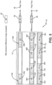
Figure 1 is a schematic perspective view of an exemplary embodiment of the system for evaluating the pressure of a tire of the present invention, shown installed in the ground and with a vehicle approaching the system; -
Figure 2 is a schematic perspective view of the system for evaluating the pressure of a tire of the present invention shown inFigure 1 ; -
Figure 3 is a schematic representation of an array of load sensors of the system shown inFigure 1 ; -
Figure 4 is a schematic representation of an aspect of the system for evaluating the pressure of a tire of the present invention shown inFigure 1 ; -
Figure 5 is a schematic representation of another aspect of the system for evaluating the pressure of a tire of the present invention shown inFigure 1 ; and -
Figure 6 is a schematic representation of a notification portion of the system for evaluating the pressure of a tire of the present invention shown inFigure 1 . - Similar numerals refer to similar parts throughout the drawings.
- "Axial" and "axially" means lines or directions that are parallel to the axis of rotation of the tire.
- "Circumferential" means lines or directions extending along the perimeter of the surface of the annular tread perpendicular to the axial direction.
- "Equatorial centerplane (CP)" means the plane perpendicular to the tire's axis of rotation and passing through the center of the tread.
- "Footprint" means the contact patch or area of contact created by the tire tread with a flat surface as the tire rotates or rolls.
- "Inboard side" means the side of the tire nearest the vehicle when the tire is mounted on a wheel and the wheel is mounted on the vehicle.
- "Lateral" means an axial direction.
- "Lateral edges" means a line tangent to the axially outermost tread contact patch or footprint of the tire as measured under normal load and tire inflation, the lines being parallel to the equatorial centerplane.
- "Net contact area" means the total area of ground contacting tread elements between the lateral edges around the entire circumference of the tread of the tire divided by the gross area of the entire tread between the lateral edges.
- "Outboard side" means the side of the tire farthest away from the vehicle when the tire is mounted on a wheel and the wheel is mounted on the vehicle.
- "Radial" and "radially" means directions radially toward or away from the axis of rotation of the tire.
- "PSI" means pounds per square inch. 1 PSI is equal to 6895 Pascal.
- With reference to
Figures 1 through 6 , an exemplary embodiment of thesystem 10 for evaluation of the pressure of a tire of the present invention is indicated. As shown inFigure 1 , thesystem 10 evaluates the pressure of eachtire 12 supporting avehicle 14. It is to be understood that thevehicle 14 may be any vehicle type and is shown by way of example as a commercial vehicle. In addition, thevehicle 14 may include any number oftires 12, and thesystem 10 may evaluate the pressure in any number of the tires on the vehicle. - The
tires 12 are preferably of conventional construction, and each tire is mounted on arespective wheel 16 as known to those skilled in the art. Eachtire 12 includes a pair ofsidewalls 18 that extend to acircumferential tread 20. As eachtire 12 rolls over theground 24, afootprint 22 is created, which is the area of contact of thetread 20 with the ground. - With additional reference to
Figures 2 and3 , thesystem 10 includes a drive overreader 26, which is mounted in or on theground 24. The drive overreader 26 includes ahousing 28 and at least onesensor 30 mounted in the housing. Preferably, an array ofload sensors 30 is mounted in thehousing 28. The driver of thevehicle 14 directs the vehicle over the drive overreader 26, which causes eachtire 12 to roll over the reader. When thetire 12 is positioned over thesensor array 30, the array measures the force exerted by the tire. - The pressure of the
tire 12 is determined from the force measured by thesensor array 30, and may incorporate tire information and/or vehicle information. An exemplary technique for determining the pressure of thetire 12 is described inU.S. Patent No. 7,942,048 . By employing the drive overreader 26, the pressure of thetire 12 is determined without invading or accessing the tire cavity. The drive overreader 26 includes, or is in electronic communication with, a processor to determine the pressure of thetire 12 from thesensor array 30. - As with any measurement technique, the precision and repeatability of the pressure determination by the drive over
reader 26 are important considerations. Therefore, thesystem 10 is employed after the pressure of eachtire 12 has been determined by the drive overreader 26 to evaluate the pressure measurements of the drive over reader. As mentioned above, thesystem 10 includes and thus is incorporated into the drive overreader 26. - Referring to
Figures 4 and5 , thesystem 10 provides an evaluation of tire pressure using a pressure differential 38 betweentires 12. More particularly, the drive overreader 26 determines a pressure indication 36 for eachtire 12 on thevehicle 14. By way of example, thevehicle 14 may include twofront tires front axle 34A, and eight additional tires mounted in dual-tire configurations ontandem axles front tandem axle 34B includes twotires tires rear tandem axle 34C includes twotires tires 12I and 12J on the right side of the axle. - In this example, for the
front axle 34A, the drive overreader 26 provides afirst pressure indication 36A of 120 pounds per square inch (PSI) for theleft tire 12A, and asecond pressure indication 36B of 90 PSI for theright tire 12B. For thefront tandem axle 34B, athird pressure indication 36C of 130 PSI is provided for thetire 12C, afourth pressure indication 36D of 140 PSI is provided for thetire 12D, afifth pressure indication 36E of 100 PSI is provided for thetire 12E, and asixth pressure indication 36F of 90 PSI is provided for thetire 12F. For therear tandem axle 34C, aseventh pressure indication 36G of 100 PSI is provided for thetire 12G, aneighth pressure indication 36H of 115 PSI is provided for thetire 12H, a ninth pressure indication 36I of 130 PSI is provided for the tire 12I, and atenth pressure indication 36J of 125 PSI is provided for thetire 12J. - The
system 10 evaluates the pressure indications 36 based upon a pressure differential 38 betweentires 12. A maximumdifferential threshold 40 is determined for the system and is set at 20 PSI in this example. Any of thetires 12 may be compared with one another. For example, twotires 12 on the same axle 34 may be compared to one another, such as theleft tire 12A and theright tire 12B on thefront axle 34A. Because theleft tire 12A has apressure indication 36A of 120 PSI and theright tire 12B has apressure indication 36B of 90 PSI, the pressure differential 38 between the tires is 30 PSI. The maximumdifferential threshold 40 is 20 PSI, and the pressure differential 38 thus exceeds the threshold. When the pressure differential 38 exceeds thethreshold 40, a notice orflag 42 is generated that thetires 12 being compared have an unacceptable pressure differential and are in a pressure condition that is not optimum for driving. - Also in the
system 10,multiple tires 12 on multiple axles 34 may be compared with one another. For example, thetires front tandem axle 34B, and thetires rear tandem axle 34C may all be compared to one another. The maximum indicated pressure 36 in this group oftires 12 is thefourth pressure indication 36D of 140 PSI for thetire 12D, and the minimum indicated pressure in this group of tires is thesixth pressure indication 36F of 90 PSI for thetire 12F, yielding amaximum pressure differential 38 of 50 PSI. The maximumdifferential threshold 40 is 20 PSI, and the maximum pressure differential 38 thus exceeds the threshold. When the pressure differential 38 exceeds thethreshold 40, thenotice 42 is generated that thetires 12 in this group have an unacceptable pressure differential and are in a pressure condition that is not optimum for driving. - Turning to
Figure 6 , thesystem 10 includes and is incorporated into the drive overreader 26. When thenotice 42 is generated, it is sent through wireless or wiredtransmission 44 along with any other pertinent drive over reader output to a receivingdevice 46. The receivingdevice 46 may be any device that communicates thenotice 42 to a technician, vehicle operator, or a fleet manager, such as a computer with a display terminal, a user device, and/or a fleet management server. - In this manner, the system for evaluation of the pressure of a
tire 10 provides an evaluation of the indicated tire pressure 36 as determined by the drive overreader 26 using a pressure differential 38 betweentires 12. The pressure differential 38 may be between all of thetires 12 or may be limited to a limited number of specifically identified tires. When the maximum pressure differential 38 is greater than apredetermined threshold 40, anotification 42 is generated. - The
system 10 evaluates the precision and repeatability of the pressure determination 36 by the drive overreader 26, and evaluates the pressure of thetires 12 in a current operating condition without the need to invade or access the tire cavity. Thesystem 10 provides an evaluation of thetires 12 at any tire temperature, as opposed to having to make reference to a recommended cold pressure (RCP) and correct the measured value for temperature compensation. - The present invention also includes a method for evaluating the pressure of a
tire 12. The method includes steps in accordance with the description that is presented above and shown inFigure 1 through 6 .
Claims (10)
- A system for evaluation of pressure of at least two tires (12) supporting a vehicle (14), the system (10) including:a drive over reader (26) including a sensor array (30);a first pressure indication, the first pressure indication being a pressure indication for a first tire determined by the drive over reader (26);a second pressure indication, the second pressure indication being a pressure indication for a second tire determined by the drive over reader (26);a maximum differential threshold (40);a pressure differential (38), the pressure differential being determined by comparing the first pressure indication to the second pressure indication; anda notice (42) generated by the drive over reader (26) when the pressure differential (38) exceeds the maximum differential threshold (40);wherein the first tire is disposed on a first axle and the second tire is disposed on a second axle; characterized in thatthe system (10) is configured to determine the pressure differential (38) by comparing a maximum indicated pressure from the plurality of tires to a minimum indicated pressure from the plurality of tires.
- The system of claim 1, wherein the system (10) is configured to transmit the notice to a receiving device, the receiving device including at least one of a computer with a display terminal, a user device, and a fleet management server.
- The system of at least one of the previous claims, wherein the system (10) is configured to evaluate the pressure of the tires (12) without invading a cavity of each tire (12).
- The system of at least one of the previous claims, wherein the system (10) is configured to evaluate the pressure of the tires (12) at any tire temperature the tires (12) may have or be exposed to.
- The system of at least one of the previous claims, wherein the sensor array (30) includes a plurality of load sensors and wherein each pressure indication is determined from force measurements generated by the sensor array (30).
- A method for evaluation of pressure of at least two tires (12) supporting a vehicle (14), the method including the steps of:providing a drive over reader (26) including a sensor array (30);determining a first pressure indication with the drive over reader (26), the first pressure indication being a pressure indication for a first tire;determining a second pressure indication with the drive over reader (26), the second pressure indication being a pressure indication for a second tire;providing a maximum differential threshold (40);determining a pressure differential (38) by comparing the first pressure indication to the second pressure indication; andgenerating a notice (42) with the drive over reader (26) when the pressure differential (38) exceeds the maximum differential threshold (40);wherein the first tire is disposed on a first axle and the second tire is disposed on a second axle; characterized in thatthe step of determining the pressure differential (38) includes comparing a maximum indicated pressure from the plurality of tires to a minimum indicated pressure from the plurality of tires.
- The method of claim 6, further comprising the step of transmitting the notice (42) to a receiving device, the receiving device including at least one of a computer with a display terminal, a user device, and a fleet management server.
- The method of at least one of the claims 6 or 7, wherein the pressure of the tires (12) is evaluated without invading a cavity of each tire.
- The method of at least one of the claims 6 to 8, wherein the pressure of the tires (12) is evaluated at any tire temperature the tires (12) may have or be exposed to.
- The method of at least one of the claims 6 to 9, wherein the sensor array (30) includes a plurality of load sensors, and wherein each pressure indication is determined from force measurements generated by the sensor array (30).
Applications Claiming Priority (1)
| Application Number | Priority Date | Filing Date | Title |
|---|---|---|---|
| US17/122,134 US20220185037A1 (en) | 2020-12-15 | 2020-12-15 | System and method for evaluation of tire pressure |
Publications (2)
| Publication Number | Publication Date |
|---|---|
| EP4016032A1 EP4016032A1 (en) | 2022-06-22 |
| EP4016032B1 true EP4016032B1 (en) | 2025-04-02 |
Family
ID=78820299
Family Applications (1)
| Application Number | Title | Priority Date | Filing Date |
|---|---|---|---|
| EP21211693.3A Active EP4016032B1 (en) | 2020-12-15 | 2021-12-01 | System and method for evaluation of tire pressure |
Country Status (5)
| Country | Link |
|---|---|
| US (1) | US20220185037A1 (en) |
| EP (1) | EP4016032B1 (en) |
| CN (1) | CN114636509A (en) |
| BR (1) | BR102021024571A2 (en) |
| CA (1) | CA3141794A1 (en) |
Families Citing this family (3)
| Publication number | Priority date | Publication date | Assignee | Title |
|---|---|---|---|---|
| US11413912B2 (en) * | 2020-12-15 | 2022-08-16 | The Goodyear Tire & Rubber Company | System and method for temperature compensation of drive over reader pressure measurement |
| WO2022232520A1 (en) * | 2021-04-30 | 2022-11-03 | Tekscan, Inc. | Contact sensors |
| CN115284796A (en) * | 2022-08-12 | 2022-11-04 | 广州瑞修得信息科技有限公司 | Method and device for calculating tire pressure deviation value of vehicle |
Family Cites Families (28)
| Publication number | Priority date | Publication date | Assignee | Title |
|---|---|---|---|---|
| US5445020A (en) * | 1991-11-29 | 1995-08-29 | Exxon Research And Engineering Company | Tire inflation sensor |
| US7103460B1 (en) * | 1994-05-09 | 2006-09-05 | Automotive Technologies International, Inc. | System and method for vehicle diagnostics |
| US20050192727A1 (en) * | 1994-05-09 | 2005-09-01 | Automotive Technologies International Inc. | Sensor Assemblies |
| US5505080A (en) * | 1994-05-12 | 1996-04-09 | Tellair Corporation | Tire pressure management system |
| US5963128A (en) * | 1994-11-22 | 1999-10-05 | Schrader-Bridgeport International, Inc. | Remote tire pressure monitoring system |
| DE19649277A1 (en) * | 1996-11-28 | 1998-06-04 | Bosch Gmbh Robert | Vehicle integrated tyre air-pressure monitoring arrangement |
| EP0997713A1 (en) * | 1998-10-29 | 2000-05-03 | K.K. Holding AG | Traffic monitoring systems |
| US6658928B1 (en) * | 1999-12-14 | 2003-12-09 | The Goodyear Tire & Rubber Company | Method of monitoring pressure in a pneumatic tire |
| US6313742B1 (en) * | 2000-08-09 | 2001-11-06 | International Truck & Engine Corp | Method and apparatus for wheel condition and load position sensing |
| DE10060392A1 (en) * | 2000-12-05 | 2002-06-20 | Volkswagen Ag | Device and method for monitoring the air pressure in the tires of a motor vehicle |
| US6400261B1 (en) * | 2001-03-29 | 2002-06-04 | The Goodyear Tire & Rubber Company | Method of monitoring a tire condition using a drive over reader |
| US7089099B2 (en) * | 2004-07-30 | 2006-08-08 | Automotive Technologies International, Inc. | Sensor assemblies |
| PT2064532E (en) * | 2006-09-19 | 2010-04-08 | Ventech Gmbh | System for detecting the pressure in a vehicle tyre and/or speed of the vehicle |
| US8519869B2 (en) * | 2008-03-21 | 2013-08-27 | Eldec Corporation | Aircraft tire pressure loop link |
| US9000923B2 (en) * | 2008-07-14 | 2015-04-07 | The Goodyear Tire & Rubber Company | Reader and method for wheel-based RFID devices |
| US7969293B2 (en) * | 2008-10-13 | 2011-06-28 | The Goodyear Tire & Rubber Company | Integrated read station for a wheel-mounted vehicle |
| GB2470903B (en) * | 2009-06-08 | 2013-01-02 | Wheelright Ltd | Vehicle tyre inflation checking system |
| US20110043342A1 (en) * | 2009-08-19 | 2011-02-24 | Peter Ross Shepler | Tire status display system for a cargo trailer |
| US20110043354A1 (en) * | 2009-08-19 | 2011-02-24 | Peter Ross Shepler | Vehicle tire monitoring system |
| US20110043343A1 (en) * | 2009-08-19 | 2011-02-24 | Peter Ross Shepler | Tire monitoring system for a tandem tractor trailer system |
| GB2494618B (en) * | 2011-08-22 | 2018-03-21 | Wheelright Ltd | Vehicle tyre pressure measurement |
| DE102012205694A1 (en) * | 2012-04-05 | 2013-10-10 | Robert Bosch Gmbh | Method and device for tire pressure testing |
| US9183423B2 (en) * | 2013-07-26 | 2015-11-10 | The Goodyear Tire & Rubber Company | Drive-over stand and antenna assembly |
| FR3030374B1 (en) * | 2014-12-17 | 2017-01-13 | Michelin & Cie | METHOD FOR DETECTING AND WARNING OF THE UNDER-INFLATION CONDITION OF A TIRE |
| DE102014226783B4 (en) * | 2014-12-22 | 2020-01-02 | Continental Automotive Gmbh | System and method for determining at least one tire tire parameter characterizing a dimension of a tire patch on a tire of a wheel of a vehicle |
| US10657739B2 (en) * | 2016-10-05 | 2020-05-19 | Solera Holdings, Inc. | Vehicle tire monitoring systems and methods |
| US11247515B2 (en) * | 2016-11-23 | 2022-02-15 | Christopher Scott Larsen | Apparatus for wheel-mounted wireless measurement of tire pressure and method for doing the same |
| US10809742B2 (en) * | 2017-03-06 | 2020-10-20 | The Goodyear Tire & Rubber Company | System and method for tire sensor-based autonomous vehicle fleet management |
-
2020
- 2020-12-15 US US17/122,134 patent/US20220185037A1/en not_active Abandoned
-
2021
- 2021-12-01 EP EP21211693.3A patent/EP4016032B1/en active Active
- 2021-12-03 BR BR102021024571-9A patent/BR102021024571A2/en not_active Application Discontinuation
- 2021-12-10 CA CA3141794A patent/CA3141794A1/en active Pending
- 2021-12-15 CN CN202111532970.2A patent/CN114636509A/en active Pending
Also Published As
| Publication number | Publication date |
|---|---|
| CA3141794A1 (en) | 2022-06-15 |
| EP4016032A1 (en) | 2022-06-22 |
| BR102021024571A2 (en) | 2023-04-18 |
| CN114636509A (en) | 2022-06-17 |
| US20220185037A1 (en) | 2022-06-16 |
Similar Documents
| Publication | Publication Date | Title |
|---|---|---|
| EP4016032B1 (en) | System and method for evaluation of tire pressure | |
| US20060090558A1 (en) | Tire wear sensor | |
| EP4029707A1 (en) | System and method for auto-location of tires | |
| EP3666554B1 (en) | Tire wear state estimation system and method | |
| EP3925805B1 (en) | Tire load estimation system and method | |
| US12263704B2 (en) | Tire irregular wear detection system and method | |
| US11506572B2 (en) | Method for locating the position of each wheelset of a motor vehicle | |
| EP4368421B1 (en) | Method and system for monitoring tire inflation pressure | |
| EP4016033B1 (en) | System and method for temperature compensation of drive over reader pressure measurement | |
| EP4151436B1 (en) | Counter-deflection load estimation system and method | |
| EP4385767B1 (en) | System and method for auto-location of tires employing footprint length | |
| CN115782473B (en) | Reverse deflection load estimation system for tire | |
| EP4368419B1 (en) | System and method for auto-location of tires employing footprint length | |
| EP4477432B1 (en) | Tire with a set of printed sensors | |
| US20260044693A1 (en) | Method for reading information contained in an rfid chip embedded in a vehicle tire | |
| EP4379346B1 (en) | Tire rolling resistance estimation system and method | |
| CN118182021A (en) | System for automatically positioning tire by utilizing print length | |
| EP4197820B1 (en) | Integrated tread wear sensor and tpms container for a tire | |
| CN120152891A (en) | System and method for vehicle control based on wheel type, space-saving wheel, vehicle, and computer program |
Legal Events
| Date | Code | Title | Description |
|---|---|---|---|
| PUAI | Public reference made under article 153(3) epc to a published international application that has entered the european phase |
Free format text: ORIGINAL CODE: 0009012 |
|
| STAA | Information on the status of an ep patent application or granted ep patent |
Free format text: STATUS: THE APPLICATION HAS BEEN PUBLISHED |
|
| AK | Designated contracting states |
Kind code of ref document: A1 Designated state(s): AL AT BE BG CH CY CZ DE DK EE ES FI FR GB GR HR HU IE IS IT LI LT LU LV MC MK MT NL NO PL PT RO RS SE SI SK SM TR |
|
| STAA | Information on the status of an ep patent application or granted ep patent |
Free format text: STATUS: REQUEST FOR EXAMINATION WAS MADE |
|
| 17P | Request for examination filed |
Effective date: 20221222 |
|
| RBV | Designated contracting states (corrected) |
Designated state(s): AL AT BE BG CH CY CZ DE DK EE ES FI FR GB GR HR HU IE IS IT LI LT LU LV MC MK MT NL NO PL PT RO RS SE SI SK SM TR |
|
| RIC1 | Information provided on ipc code assigned before grant |
Ipc: G01L 17/00 20060101AFI20240919BHEP |
|
| GRAP | Despatch of communication of intention to grant a patent |
Free format text: ORIGINAL CODE: EPIDOSNIGR1 |
|
| STAA | Information on the status of an ep patent application or granted ep patent |
Free format text: STATUS: GRANT OF PATENT IS INTENDED |
|
| INTG | Intention to grant announced |
Effective date: 20241104 |
|
| RIN1 | Information on inventor provided before grant (corrected) |
Inventor name: BUSSMANN, STEFAN Inventor name: PIETSCH, ANDREAS MICHALE THOMAS Inventor name: GANGULY, ABHIJIT Inventor name: COLLIN, PIERRE JULES A. |
|
| GRAS | Grant fee paid |
Free format text: ORIGINAL CODE: EPIDOSNIGR3 |
|
| GRAA | (expected) grant |
Free format text: ORIGINAL CODE: 0009210 |
|
| STAA | Information on the status of an ep patent application or granted ep patent |
Free format text: STATUS: THE PATENT HAS BEEN GRANTED |
|
| AK | Designated contracting states |
Kind code of ref document: B1 Designated state(s): AL AT BE BG CH CY CZ DE DK EE ES FI FR GB GR HR HU IE IS IT LI LT LU LV MC MK MT NL NO PL PT RO RS SE SI SK SM TR |
|
| REG | Reference to a national code |
Ref country code: GB Ref legal event code: FG4D |
|
| REG | Reference to a national code |
Ref country code: CH Ref legal event code: EP |
|
| REG | Reference to a national code |
Ref country code: IE Ref legal event code: FG4D |
|
| REG | Reference to a national code |
Ref country code: DE Ref legal event code: R096 Ref document number: 602021028461 Country of ref document: DE |
|
| REG | Reference to a national code |
Ref country code: NL Ref legal event code: MP Effective date: 20250402 |
|
| PG25 | Lapsed in a contracting state [announced via postgrant information from national office to epo] |
Ref country code: NL Free format text: LAPSE BECAUSE OF FAILURE TO SUBMIT A TRANSLATION OF THE DESCRIPTION OR TO PAY THE FEE WITHIN THE PRESCRIBED TIME-LIMIT Effective date: 20250402 |
|
| REG | Reference to a national code |
Ref country code: AT Ref legal event code: MK05 Ref document number: 1781696 Country of ref document: AT Kind code of ref document: T Effective date: 20250402 |
|
| PG25 | Lapsed in a contracting state [announced via postgrant information from national office to epo] |
Ref country code: FI Free format text: LAPSE BECAUSE OF FAILURE TO SUBMIT A TRANSLATION OF THE DESCRIPTION OR TO PAY THE FEE WITHIN THE PRESCRIBED TIME-LIMIT Effective date: 20250402 Ref country code: PT Free format text: LAPSE BECAUSE OF FAILURE TO SUBMIT A TRANSLATION OF THE DESCRIPTION OR TO PAY THE FEE WITHIN THE PRESCRIBED TIME-LIMIT Effective date: 20250804 Ref country code: ES Free format text: LAPSE BECAUSE OF FAILURE TO SUBMIT A TRANSLATION OF THE DESCRIPTION OR TO PAY THE FEE WITHIN THE PRESCRIBED TIME-LIMIT Effective date: 20250402 |
|
| REG | Reference to a national code |
Ref country code: LT Ref legal event code: MG9D |
|
| PG25 | Lapsed in a contracting state [announced via postgrant information from national office to epo] |
Ref country code: NO Free format text: LAPSE BECAUSE OF FAILURE TO SUBMIT A TRANSLATION OF THE DESCRIPTION OR TO PAY THE FEE WITHIN THE PRESCRIBED TIME-LIMIT Effective date: 20250702 Ref country code: GR Free format text: LAPSE BECAUSE OF FAILURE TO SUBMIT A TRANSLATION OF THE DESCRIPTION OR TO PAY THE FEE WITHIN THE PRESCRIBED TIME-LIMIT Effective date: 20250703 |
|
| PG25 | Lapsed in a contracting state [announced via postgrant information from national office to epo] |
Ref country code: PL Free format text: LAPSE BECAUSE OF FAILURE TO SUBMIT A TRANSLATION OF THE DESCRIPTION OR TO PAY THE FEE WITHIN THE PRESCRIBED TIME-LIMIT Effective date: 20250402 |
|
| PG25 | Lapsed in a contracting state [announced via postgrant information from national office to epo] |
Ref country code: BG Free format text: LAPSE BECAUSE OF FAILURE TO SUBMIT A TRANSLATION OF THE DESCRIPTION OR TO PAY THE FEE WITHIN THE PRESCRIBED TIME-LIMIT Effective date: 20250402 |
|
| PG25 | Lapsed in a contracting state [announced via postgrant information from national office to epo] |
Ref country code: HR Free format text: LAPSE BECAUSE OF FAILURE TO SUBMIT A TRANSLATION OF THE DESCRIPTION OR TO PAY THE FEE WITHIN THE PRESCRIBED TIME-LIMIT Effective date: 20250402 |
|
| PG25 | Lapsed in a contracting state [announced via postgrant information from national office to epo] |
Ref country code: AT Free format text: LAPSE BECAUSE OF FAILURE TO SUBMIT A TRANSLATION OF THE DESCRIPTION OR TO PAY THE FEE WITHIN THE PRESCRIBED TIME-LIMIT Effective date: 20250402 |
|
| PG25 | Lapsed in a contracting state [announced via postgrant information from national office to epo] |
Ref country code: RS Free format text: LAPSE BECAUSE OF FAILURE TO SUBMIT A TRANSLATION OF THE DESCRIPTION OR TO PAY THE FEE WITHIN THE PRESCRIBED TIME-LIMIT Effective date: 20250702 |
|
| PG25 | Lapsed in a contracting state [announced via postgrant information from national office to epo] |
Ref country code: IS Free format text: LAPSE BECAUSE OF FAILURE TO SUBMIT A TRANSLATION OF THE DESCRIPTION OR TO PAY THE FEE WITHIN THE PRESCRIBED TIME-LIMIT Effective date: 20250802 |
|
| PG25 | Lapsed in a contracting state [announced via postgrant information from national office to epo] |
Ref country code: LV Free format text: LAPSE BECAUSE OF FAILURE TO SUBMIT A TRANSLATION OF THE DESCRIPTION OR TO PAY THE FEE WITHIN THE PRESCRIBED TIME-LIMIT Effective date: 20250402 |
|
| REG | Reference to a national code |
Ref country code: DE Ref legal event code: R097 Ref document number: 602021028461 Country of ref document: DE |
|
| PGFP | Annual fee paid to national office [announced via postgrant information from national office to epo] |
Ref country code: DE Payment date: 20251126 Year of fee payment: 5 |
|
| PGFP | Annual fee paid to national office [announced via postgrant information from national office to epo] |
Ref country code: GB Payment date: 20251119 Year of fee payment: 5 |
|
| PG25 | Lapsed in a contracting state [announced via postgrant information from national office to epo] |
Ref country code: SM Free format text: LAPSE BECAUSE OF FAILURE TO SUBMIT A TRANSLATION OF THE DESCRIPTION OR TO PAY THE FEE WITHIN THE PRESCRIBED TIME-LIMIT Effective date: 20250402 Ref country code: DK Free format text: LAPSE BECAUSE OF FAILURE TO SUBMIT A TRANSLATION OF THE DESCRIPTION OR TO PAY THE FEE WITHIN THE PRESCRIBED TIME-LIMIT Effective date: 20250402 |
|
| PGFP | Annual fee paid to national office [announced via postgrant information from national office to epo] |
Ref country code: IT Payment date: 20251119 Year of fee payment: 5 |
|
| PGFP | Annual fee paid to national office [announced via postgrant information from national office to epo] |
Ref country code: FR Payment date: 20251120 Year of fee payment: 5 |
|
| PG25 | Lapsed in a contracting state [announced via postgrant information from national office to epo] |
Ref country code: CZ Free format text: LAPSE BECAUSE OF FAILURE TO SUBMIT A TRANSLATION OF THE DESCRIPTION OR TO PAY THE FEE WITHIN THE PRESCRIBED TIME-LIMIT Effective date: 20250402 |
|
| PG25 | Lapsed in a contracting state [announced via postgrant information from national office to epo] |
Ref country code: EE Free format text: LAPSE BECAUSE OF FAILURE TO SUBMIT A TRANSLATION OF THE DESCRIPTION OR TO PAY THE FEE WITHIN THE PRESCRIBED TIME-LIMIT Effective date: 20250402 |
|
| PG25 | Lapsed in a contracting state [announced via postgrant information from national office to epo] |
Ref country code: RO Free format text: LAPSE BECAUSE OF FAILURE TO SUBMIT A TRANSLATION OF THE DESCRIPTION OR TO PAY THE FEE WITHIN THE PRESCRIBED TIME-LIMIT Effective date: 20250402 Ref country code: SK Free format text: LAPSE BECAUSE OF FAILURE TO SUBMIT A TRANSLATION OF THE DESCRIPTION OR TO PAY THE FEE WITHIN THE PRESCRIBED TIME-LIMIT Effective date: 20250402 |
|
| PLBE | No opposition filed within time limit |
Free format text: ORIGINAL CODE: 0009261 |
|
| STAA | Information on the status of an ep patent application or granted ep patent |
Free format text: STATUS: NO OPPOSITION FILED WITHIN TIME LIMIT |
|
| REG | Reference to a national code |
Ref country code: CH Ref legal event code: L10 Free format text: ST27 STATUS EVENT CODE: U-0-0-L10-L00 (AS PROVIDED BY THE NATIONAL OFFICE) Effective date: 20260211 |
|
| 26N | No opposition filed |
Effective date: 20260105 |