EP4015812A1 - Gas turbine engine exhaust chevrons - Google Patents
Gas turbine engine exhaust chevrons Download PDFInfo
- Publication number
- EP4015812A1 EP4015812A1 EP21216217.6A EP21216217A EP4015812A1 EP 4015812 A1 EP4015812 A1 EP 4015812A1 EP 21216217 A EP21216217 A EP 21216217A EP 4015812 A1 EP4015812 A1 EP 4015812A1
- Authority
- EP
- European Patent Office
- Prior art keywords
- chevron
- ring
- hollow portion
- core
- various embodiments
- Prior art date
- Legal status (The legal status is an assumption and is not a legal conclusion. Google has not performed a legal analysis and makes no representation as to the accuracy of the status listed.)
- Pending
Links
Images





Classifications
-
- F—MECHANICAL ENGINEERING; LIGHTING; HEATING; WEAPONS; BLASTING
- F02—COMBUSTION ENGINES; HOT-GAS OR COMBUSTION-PRODUCT ENGINE PLANTS
- F02K—JET-PROPULSION PLANTS
- F02K1/00—Plants characterised by the form or arrangement of the jet pipe or nozzle; Jet pipes or nozzles peculiar thereto
- F02K1/46—Nozzles having means for adding air to the jet or for augmenting the mixing region between the jet and the ambient air, e.g. for silencing
- F02K1/48—Corrugated nozzles
-
- F—MECHANICAL ENGINEERING; LIGHTING; HEATING; WEAPONS; BLASTING
- F02—COMBUSTION ENGINES; HOT-GAS OR COMBUSTION-PRODUCT ENGINE PLANTS
- F02K—JET-PROPULSION PLANTS
- F02K1/00—Plants characterised by the form or arrangement of the jet pipe or nozzle; Jet pipes or nozzles peculiar thereto
- F02K1/38—Introducing air inside the jet
- F02K1/386—Introducing air inside the jet mixing devices in the jet pipe, e.g. for mixing primary and secondary flow
-
- F—MECHANICAL ENGINEERING; LIGHTING; HEATING; WEAPONS; BLASTING
- F02—COMBUSTION ENGINES; HOT-GAS OR COMBUSTION-PRODUCT ENGINE PLANTS
- F02K—JET-PROPULSION PLANTS
- F02K3/00—Plants including a gas turbine driving a compressor or a ducted fan
- F02K3/02—Plants including a gas turbine driving a compressor or a ducted fan in which part of the working fluid by-passes the turbine and combustion chamber
- F02K3/04—Plants including a gas turbine driving a compressor or a ducted fan in which part of the working fluid by-passes the turbine and combustion chamber the plant including ducted fans, i.e. fans with high volume, low pressure outputs, for augmenting the jet thrust, e.g. of double-flow type
- F02K3/06—Plants including a gas turbine driving a compressor or a ducted fan in which part of the working fluid by-passes the turbine and combustion chamber the plant including ducted fans, i.e. fans with high volume, low pressure outputs, for augmenting the jet thrust, e.g. of double-flow type with front fan
-
- F—MECHANICAL ENGINEERING; LIGHTING; HEATING; WEAPONS; BLASTING
- F05—INDEXING SCHEMES RELATING TO ENGINES OR PUMPS IN VARIOUS SUBCLASSES OF CLASSES F01-F04
- F05D—INDEXING SCHEME FOR ASPECTS RELATING TO NON-POSITIVE-DISPLACEMENT MACHINES OR ENGINES, GAS-TURBINES OR JET-PROPULSION PLANTS
- F05D2220/00—Application
- F05D2220/30—Application in turbines
- F05D2220/32—Application in turbines in gas turbines
- F05D2220/323—Application in turbines in gas turbines for aircraft propulsion, e.g. jet engines
-
- F—MECHANICAL ENGINEERING; LIGHTING; HEATING; WEAPONS; BLASTING
- F05—INDEXING SCHEMES RELATING TO ENGINES OR PUMPS IN VARIOUS SUBCLASSES OF CLASSES F01-F04
- F05D—INDEXING SCHEME FOR ASPECTS RELATING TO NON-POSITIVE-DISPLACEMENT MACHINES OR ENGINES, GAS-TURBINES OR JET-PROPULSION PLANTS
- F05D2240/00—Components
- F05D2240/10—Stators
- F05D2240/12—Fluid guiding means, e.g. vanes
- F05D2240/128—Nozzles
-
- F—MECHANICAL ENGINEERING; LIGHTING; HEATING; WEAPONS; BLASTING
- F05—INDEXING SCHEMES RELATING TO ENGINES OR PUMPS IN VARIOUS SUBCLASSES OF CLASSES F01-F04
- F05D—INDEXING SCHEME FOR ASPECTS RELATING TO NON-POSITIVE-DISPLACEMENT MACHINES OR ENGINES, GAS-TURBINES OR JET-PROPULSION PLANTS
- F05D2250/00—Geometry
- F05D2250/10—Two-dimensional
- F05D2250/18—Two-dimensional patterned
- F05D2250/182—Two-dimensional patterned crenellated, notched
-
- F—MECHANICAL ENGINEERING; LIGHTING; HEATING; WEAPONS; BLASTING
- F05—INDEXING SCHEMES RELATING TO ENGINES OR PUMPS IN VARIOUS SUBCLASSES OF CLASSES F01-F04
- F05D—INDEXING SCHEME FOR ASPECTS RELATING TO NON-POSITIVE-DISPLACEMENT MACHINES OR ENGINES, GAS-TURBINES OR JET-PROPULSION PLANTS
- F05D2250/00—Geometry
- F05D2250/10—Two-dimensional
- F05D2250/18—Two-dimensional patterned
- F05D2250/183—Two-dimensional patterned zigzag
-
- F—MECHANICAL ENGINEERING; LIGHTING; HEATING; WEAPONS; BLASTING
- F05—INDEXING SCHEMES RELATING TO ENGINES OR PUMPS IN VARIOUS SUBCLASSES OF CLASSES F01-F04
- F05D—INDEXING SCHEME FOR ASPECTS RELATING TO NON-POSITIVE-DISPLACEMENT MACHINES OR ENGINES, GAS-TURBINES OR JET-PROPULSION PLANTS
- F05D2250/00—Geometry
- F05D2250/10—Two-dimensional
- F05D2250/18—Two-dimensional patterned
- F05D2250/184—Two-dimensional patterned sinusoidal
-
- F—MECHANICAL ENGINEERING; LIGHTING; HEATING; WEAPONS; BLASTING
- F05—INDEXING SCHEMES RELATING TO ENGINES OR PUMPS IN VARIOUS SUBCLASSES OF CLASSES F01-F04
- F05D—INDEXING SCHEME FOR ASPECTS RELATING TO NON-POSITIVE-DISPLACEMENT MACHINES OR ENGINES, GAS-TURBINES OR JET-PROPULSION PLANTS
- F05D2250/00—Geometry
- F05D2250/10—Two-dimensional
- F05D2250/18—Two-dimensional patterned
- F05D2250/185—Two-dimensional patterned serpentine-like
-
- F—MECHANICAL ENGINEERING; LIGHTING; HEATING; WEAPONS; BLASTING
- F05—INDEXING SCHEMES RELATING TO ENGINES OR PUMPS IN VARIOUS SUBCLASSES OF CLASSES F01-F04
- F05D—INDEXING SCHEME FOR ASPECTS RELATING TO NON-POSITIVE-DISPLACEMENT MACHINES OR ENGINES, GAS-TURBINES OR JET-PROPULSION PLANTS
- F05D2260/00—Function
- F05D2260/96—Preventing, counteracting or reducing vibration or noise
Definitions
- the present disclosure (invention) relates generally to gas turbine engines and, more particularly, to gas turbine engine systems having exhaust systems configured to reduce acoustic noise.
- Gas turbine engines typically include a compressor section, a combustor section and a turbine section. During operation, air is pressurized in the compressor section and is mixed with fuel and burned in the combustor section to generate hot combustion gases. The hot combustion gases are communicated through the turbine section, which extracts energy from the hot combustion gases to power the compressor section and other gas turbine engine loads.
- Both the compressor section and the turbine section may include alternating series of rotating blades and stationary vanes that extend into a core flow path of the gas turbine engine.
- turbine blades rotate and extract energy from the hot combustion gases that are communicated along the core flow path of the gas turbine engine.
- the turbine vanes which generally do not rotate, guide the airflow and prepare it for the next set of blades.
- the generation of noise from gas turbine engine exhaust systems is of significant practical interest for low and moderate bypass ratio engines used in subsonic civil transports.
- the gas turbine engine exhaust noise is one component of overall engine noise and is particularly important at take-off and cutback conditions.
- the gas turbine engine noise contribution is reduced, for example, by using a geared gas turbine engine, but noise is still a factor especially with continually tightening of noise restrictions.
- a chevron ring includes an attachment ring; and a chevron, the chevron connected to and extending downstream of the attachment ring and having a trailing edge portion, the chevron defining a hollow portion between the attachment ring and the trailing edge portion.
- the chevron ring defines a nominal surface area bounded by the attachment ring and the trailing edge portion and the hollow portion defines a cutout surface area of between twenty percent and ninety percent of the nominal surface area.
- the chevron ring defines a nominal thickness at the trailing edge portion and the hollow portion defines a depth of between twenty percent and ninety percent of the nominal thickness.
- a cover skin is configured to cover the hollow portion.
- the hollow portion comprises a plurality of holes.
- the chevron ring comprises a multi-piece-chevron ring.
- the chevron ring defines a nominal surface area bounded by the attachment ring and the trailing edge portion and the hollow portion defines a cutout surface area of between twenty percent and ninety percent of the nominal surface area and the hollow portion extends completely through a nominal thickness of the chevron ring.
- a first cover skin is configured to cover a radially outer side of the hollow portion and a second cover skin is configured to cover a radially inner side of the hollow portion.
- the hollow portion comprises a plurality of holes.
- the chevron ring comprises a multi-piece-chevron ring.
- an exhaust nozzle includes a core; and a chevron ring attached to the core, the chevron ring including an attachment portion and a chevron, the chevron connected to and extending downstream of the attachment portion and having a trailing edge portion, the chevron defining a hollow portion between the attachment portion and the trailing edge portion.
- the attachment portion is attached to the core via at least one fastener or a weld.
- the attachment portion is attached to the core via a rotary friction weld.
- the chevron ring defines a nominal surface area bounded by the attachment portion and the trailing edge portion and the hollow portion defines a cutout surface area of between twenty percent and ninety percent of the nominal surface area.
- the chevron ring defines a nominal thickness at the trailing edge portion and the hollow portion defines a depth of between twenty percent and ninety percent of the nominal thickness.
- a cover skin is configured to cover the hollow portion.
- the hollow portion comprises a plurality of holes.
- the chevron ring defines a nominal surface area bounded by the attachment portion and the trailing edge portion and the hollow portion defines a cutout surface area of between twenty percent and ninety percent of the nominal surface area and the hollow portion extends completely through a nominal thickness of the chevron ring.
- a first cover skin configured to cover a radially outer side of the hollow portion and a second cover skin configured to cover a radially inner side of the hollow portion.
- the hollow portion comprises a plurality of holes.
- references to "a,” “an” or “the” may include one or more than one and that reference to an item in the singular may also include the item in the plural. Further, all ranges may include upper and lower values and all ranges and ratio limits disclosed herein may be combined.
- FIG. 1 schematically illustrates a gas turbine engine 20.
- the gas turbine engine 20 is disclosed herein as a two-spool turbofan that generally incorporates a fan section 22, a compressor section 24, a combustor section 26 and a turbine section 28.
- the fan section 22 drives air along a bypass flow path B in a bypass duct defined within a nacelle 15, while the compressor section 24 drives air along a core flow path C for compression and communication into the combustor section 26 and then expansion through the turbine section 28.
- the concepts described herein are not limited to use with two-spool turbofans as the teachings may be applied to other types of turbine engines.
- the gas turbine engine 20 generally includes a low speed spool 30 and a high speed spool 32 mounted for rotation about an engine central longitudinal axis A relative to an engine static structure 36 via several bearing systems 38.
- the low speed spool 30 generally includes an inner shaft 40 that interconnects a fan 42, a low pressure compressor 44 and a low pressure turbine 46.
- the inner shaft 40 is connected to the fan 42 through a speed change mechanism, which in this gas turbine engine 20 is illustrated as a fan drive gear system 48 configured to drive the fan 42 at a lower speed than that of the low speed spool 30.
- the high speed spool 32 includes an outer shaft 50 that interconnects a high pressure compressor 52 and a high pressure turbine 54.
- a combustor 56 is arranged in the gas turbine engine 20 between the high pressure compressor 52 and the high pressure turbine 54.
- a mid-turbine frame 57 of the engine static structure 36 is arranged generally between the high pressure turbine 54 and the low pressure turbine 46 and may include airfoils 59 in the core flow path C for guiding the flow into the low pressure turbine 46.
- the mid-turbine frame 57 further supports the several bearing systems 38 in the turbine section 28.
- the inner shaft 40 and the outer shaft 50 are concentric and rotate via the several bearing systems 38 about the engine central longitudinal axis A, which is collinear with longitudinal axes of the inner shaft 40 and the outer shaft 50.
- the air in the core flow path C is compressed by the low pressure compressor 44 and then the high pressure compressor 52, mixed and burned with fuel in the combustor 56, and then expanded over the high pressure turbine 54 and the low pressure turbine 46.
- the low pressure turbine 46 and the high pressure turbine 54 rotationally drive respectively, the low speed spool 30 and the high speed spool 32 in response to the expansion.
- each of the positions of the fan section 22, the compressor section 24, the combustor section 26, the turbine section 28, and the fan drive gear system 48 may be varied.
- the fan drive gear system 48 may be located aft of the combustor section 26 or even aft of the turbine section 28, and the fan section 22 may be positioned forward or aft of the location of the fan drive gear system 48.
- the compressor section 24, the combustor section 26 and the turbine section 28 comprise a core engine arranged within a core nacelle 64.
- a tail cone 66 is arranged downstream from the core engine and is radially inward of the core nacelle 64.
- a core engine exhaust E exits the core engine between the core nacelle 64 and the tail cone 66.
- a fan nacelle 62 at least surrounds the core nacelle 64.
- the fan 42 is disposed inside the fan nacelle 62 upstream from the core engine and core nacelle 64.
- the fan nacelle 62 provides an inlet 63 that receives airflow into the gas turbine engine 20.
- the bypass flow path B exits between the fan nacelle 62 and core nacelle 64.
- a geared gas turbine engine has a unique noise signature that is not present in non-geared gas turbine engines. More specifically, unlike conventional two spool gas turbine engines in which the fan rotates at the same speed as the low pressure compressor and the low pressure turbine, the gear of the exemplary embodiments herein enables the fan to rotate slower while at the same time enabling the low pressure compressor and the low pressure turbine to rotate faster.
- the exhaust configuration is tuned to reduce the type of noise unique to a geared gas turbine engine, though the disclosure contemplates applicability to any type of gas turbine engine, including one or both of the core engine exhaust Ec and bypass flow path exhaust E B .
- FIGS. 2A, 2B and 2C various configurations for both the core engine exhaust E C (about a tail cone, such as, for example, the tail cone 66 described above with reference to FIG. 1 ) and the bypass flow path exhaust E B are illustrated.
- a fan nacelle 62 1 exhibits a fan nozzle 63 1 having a round exhaust profile
- a core nacelle 64 1 exhibits a core nozzle 65 1 having a plurality of chevrons 70 spaced about its circumference.
- a fan nacelle 62 2 exhibits a fan nozzle 63 2 having a plurality of chevrons 70 spaced about its circumference, while a core nacelle 64 2 exhibits a core nozzle 65 2 having a round exhaust profile.
- a fan nacelle 62 3 exhibits a fan nozzle 63 3 having a plurality of chevrons 70 spaced about its circumference and a core nacelle 64 3 that also has a plurality of chevrons 70 spaced about its circumference. Note that while the disclosure is directed primarily to various embodiments, represented by FIG. 2A , the disclosure is considered equally applicable to the various embodiments represented by FIGS. 2B and 2C .
- chevron is intended to refer to a noise reduction feature positioned on or integrated into the core nozzle or the bypass nozzle.
- the chevrons are incorporated into the downstream exits of the nozzles to reduce noise and may comprise a variety of configurations, including triangular, circular, sinuous and elliptical shapes, among other shapes. Without loss of generality, this disclosure generally illustrates and describes sinuous shapes, but contemplates other shapes as well.
- the nozzle assembly 300 includes a tail cone 302, a fairing 304, a fire seal 306, an attachment flange 308 and a chevron ring 310, where the chevron ring 310 includes a chevron 312 (or a plurality of chevrons 314) extending from a core 316.
- the core 316 includes an inner skin 318 and an outer skin 320 configured to sandwich an interior that, in various embodiments, may include a honeycomb structure 319 configured to suppress noise.
- a fairing skin 321 covers the core 316 and aerodynamically transitions into an upstream end of the chevron ring 310.
- the chevron ring 310 may be attached to the core 316 using various techniques, including, without limitation, liquid interface diffusion bonding, welding, fasteners or combinations thereof.
- FIGS. 4A, 4B , 4C, 4D and 4E various embodiments of a chevron ring 410 and methods of attaching the chevron ring 410 to a core 416 to form a nozzle assembly 400 are described.
- FIGS. 4A and 4B perspective and cross-sectional views of the chevron ring 410 are provided.
- the chevron ring 410 includes a chevron 412 (or a plurality of chevrons 414).
- the chevron 412 includes a downstream periphery 422 that defines a sinuous shape and provides an outer border for a hollow portion 424 (or a partially hollow portion) which, as illustrated in FIG.
- a shell portion 436 spans a surface area of the chevron 412 and provides a lower surface or a floor for the hollow portion 424.
- a trailing edge portion 430 tracks the downstream periphery 422 in the sinuous shape referred to above and includes a downstream step portion 434 configured to receive a trailing edge portion of a cover skin configured to cover the hollow portion 424.
- the upstream attachment portion 438 includes an upstream step portion 435 configured to receive an upstream edge portion of the cover skin configured to cover the hollow portion 424.
- the chevron 412 defines a nominal thickness at the downstream portion 432 and the hollow portion 424 defines a depth of about twenty percent (20%) to about ninety percent (90%) of the nominal thickness, or, in various embodiments, a depth of about forty percent (40%) to about ninety percent (90%) of the nominal thickness, or, in various embodiments, a depth of about sixty percent (60%) to about ninety percent (90%) of the nominal thickness.
- the chevron 412 defines a nominal surface area bounded by the upstream attachment portion 438 and the downstream portion 432, and the hollow portion 424 defines a cutout surface area of about twenty percent (20%) to about ninety percent (90%) of the nominal surface area, or, in various embodiments, a cutout surface area of about forty percent (40%) to about ninety percent (90%) of the nominal surface area or, in various embodiments, a cutout surface area of about sixty percent (60%) to about ninety percent (90%) of the nominal surface area.
- FIGS. 4C, 4D and 4E various methods of attaching the chevron ring 410 to the core 416 are described.
- the chevron ring 410 having the hollow portion 424 is illustrated with a cover skin 440 extending from the downstream step portion 434 to the upstream step portion 435.
- the cover skin 440 is secured via an adhesive, a weld or otherwise fastened to the downstream step portion 434 and to the upstream step portion 435.
- the upstream attachment portion 438 includes a radially inner flange 450 that is welded to a closeout seal 409 about the circumference of the chevron ring 410.
- the upstream attachment portion 438 also includes a radially outer flange 452 that is welded to the closeout seal 409.
- a fairing skin 421 may be fastened via a fastener 454, or via a plurality of fasteners spaced circumferentially about the radially outer flange 452.
- the closeout seal 409 is secured to the core 416 via any suitable technique, such as, for example, an adhesive or other suitable fastener.
- the chevron 412 includes the hollow portion 424 bounded by shell portion 436 and the cover skin 440 extending from the downstream step portion 434 to the upstream step portion 435.
- the upstream attachment portion 438 is welded to a panel ring 460 at a circumferential face 462 that extends from a radially inner surface 463 to a radially outer surface 464 of the upstream attachment portion 438 and the panel ring 460.
- the welding at the circumferential face 462 is accomplished via a rotary friction process, whereby the two surfaces meeting at the circumferential face 462 are heated until they reach a plastic state and then forged together by an axial load, creating a welded joint (or a rotary friction weld) across the circumferential face 462.
- chevron 412 includes the hollow portion 424 bounded by shell portion 436 and the cover skin 440 extending from the downstream step portion 434 to the upstream step portion 435.
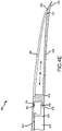
- the upstream attachment portion 438 includes a radially inner flange 450 that is fastened via a fastener 458, or via a plurality of fasteners spaced circumferentially about the radially inner flange 450, to a closeout seal 409.
- the upstream attachment portion 438 also includes a radially outer flange 452 that is similarly fastened to the fairing skin 421 via a fastener 454, or via a plurality of fasteners spaced circumferentially about the radially outer flange 452.
- the closeout seal 409 is secured to the core 416 via any suitable technique, such as, for example, an adhesive or other suitable fastener.
- FIGS. 5A and 5B various embodiments of a chevron ring 510 and methods of attaching the chevron ring 510 to a core 516 to form a nozzle assembly 500 are described.
- FIG. 5A a perspective view of the chevron ring 510 is provided.
- the chevron ring 510 includes a chevron 512 (or a plurality of chevrons 514).
- the chevron 512 includes a downstream periphery 522 that defines a sinuous shape and provides an outer border for a hollow portion 525 which, as illustrated in FIG. 5B , spans from a downstream portion 532 to an upstream attachment portion 538.
- the hollow portion 525 is a fully hollow portion that extends completely through the chevron 512.
- a trailing edge portion 530 tracks the downstream periphery 522 in the sinuous shape referred to above and includes a first downstream step portion 534 configured to receive a trailing edge portion of a cover skin configured to cover the hollow portion 525.
- the upstream attachment portion 538 includes a first upstream step portion 535 configured to receive an upstream edge portion of the cover skin configured to cover the hollow portion 525.
- the chevron ring 510 having the hollow portion 525 is illustrated with a first cover skin 540 extending from the first downstream step portion 534 to the first upstream step portion 535.
- the first cover skin 540 is secured via an adhesive, a weld or otherwise fastened to the first downstream step portion 534 and to the first upstream step portion 535.
- the chevron ring 510 is illustrated with a second cover skin 570 extending from a second downstream step portion 533 to a second upstream step portion 537.
- the second cover skin 570 is secured via an adhesive or otherwise welded or fastened to the second downstream step portion 533 and to the second upstream step portion 537.
- the first cover skin 540 and the second cover skin 570 enclose the hollow portion 525.
- the upstream attachment portion 538 includes a radially inner flange 550 that is fastened via a fastener 558, or via a plurality of fasteners spaced circumferentially about the radially inner flange 550, to a closeout seal 509.
- the upstream attachment portion 538 also includes a radially outer flange 552 that is similarly fastened to a fairing skin 521 via a fastener 554, or via a plurality of fasteners spaced circumferentially about the radially outer flange 552.
- the closeout seal 509 is secured to the core 516 via any suitable technique, such as, for example, an adhesive or other suitable fastener. While FIG. 5B includes a similar manner of attachment as described in reference to FIG. 4E , the disclosure is not limiting in this regard, and contemplates the manners of attachment described in reference to FIGS. 4C and 4D as well.
- the chevron ring 610 includes a chevron 612 (or a plurality of chevrons 614).
- the chevron 612 includes a downstream periphery 622 that defines a sinuous shape. Similar to the above description regarding the chevron ring 410 and the chevron ring 510, the chevron ring 610 spans from a downstream portion 632 to an upstream attachment portion 638.
- the chevron ring 610 includes a plurality of holes 670, each of which may be formed to extend partially through the chevron ring 610 or fully through the chevron ring 610.
- each of the manners of attachment of the chevron ring 410 and the chevron ring 510 to, respectively, the closeout seal 409 and the closeout seal 509 and to the core 416 and the core 516 are contemplated for the chevron ring 610.
- each of the manners of attachment of the cover skins e.g ., the cover skin 440 described with reference to FIGS. 4C-4E or one or both of the first cover skin 540 and the second cover skin 570 described with reference to FIG. 5B ) are contemplated by this disclosure as suitable for covering the plurality of holes 670. Accordingly, those details are not repeated here.
- the multi-piece-chevron ring 710 includes a chevron 712 (or a plurality of chevrons 714).
- the chevron 712 includes a downstream periphery 722 that defines a sinuous shape.
- the multi-piece-chevron ring 710 spans from a downstream portion 732 to an upstream attachment portion 738.
- the multi-piece-chevron ring 710 is fabricated from multiple segments, such as, for example, a first segment 790 having a first chevron 791 and a second chevron 792 and a second segment 793 having a third chevron 794 and a fourth chevron 795.
- each of the segments are identical in shape, meaning a single forging unit may be employed to fabricate the various segments.
- the multi-piece-chevron ring 710 also includes a pylon segment 780 configured for attachment proximate a pylon of an aircraft.
- each of the configurations described above for the chevron ring 410 having the hollow portion 424 (or the partially hollow portion) and the chevron ring 510 having the hollow portion 524 (or the fully hollow portion) are contemplated as applicable to the multi-piece-chevron ring 710, and each of the manners of attachment of the cover skins (e.g ., the cover skin 440 described with reference to FIGS. 4C-4E or one or both of the first cover skin 540 and the second cover skin 570 described with reference to FIG. 5B ) are contemplated as applicable to the multi-piece-chevron ring 710.
- each of the manners of attachment of the chevron ring 410 and the chevron ring 510 to, respectively, the closeout seal 409 and the closeout seal 509 and to the core 416 and the core 516 are contemplated as applicable for the multi-piece-chevron ring 710. Accordingly, those details are not repeated here.
- the foregoing disclosure provides a chevron ring that is lightweight and relatively straightforward to manufacture.
- the various components of the chevron rings disclosed above may be fabricated ( e . g ., forged) from any high temperature capable material, such as, for example, titanium or various alloys of titanium ( e . g ., Ti-6-4).
- the resulting chevron rings exhibit a weight saving of more than fifty percent (50%) over their constant thickness counterparts (e . g ., chevron rings having chevrons with no hollow portion).
- the resulting chevron rings are also readily amenable to attachment to core structures ( e . g ., via welding or fasteners) to provide finished engine components such as, for example, core engine exhaust nozzle structures or assembled gas turbine engine structures having the benefits described above.
- references to "one embodiment,” “an embodiment,” “various embodiments,” etc. indicate that the embodiment described may include a particular feature, structure, or characteristic, but every embodiment may not necessarily include the particular feature, structure, or characteristic. Moreover, such phrases are not necessarily referring to the same embodiment. Further, when a particular feature, structure, or characteristic is described in connection with an embodiment, it is submitted that it is within the knowledge of one skilled in the art to affect such feature, structure, or characteristic in connection with other embodiments whether or not explicitly described. After reading the description, it will be apparent to one skilled in the relevant art(s) how to implement the disclosure in alternative embodiments.
- Numbers, percentages, or other values stated herein are intended to include that value, and also other values that are about or approximately equal to the stated value, as would be appreciated by one of ordinary skill in the art encompassed by various embodiments of the present disclosure.
- a stated value should therefore be interpreted broadly enough to encompass values that are at least close enough to the stated value to perform a desired function or achieve a desired result.
- the stated values include at least the variation to be expected in a suitable industrial process, and may include values that are within 10%, within 5%, within 1%, within 0.1%, or within 0.01% of a stated value.
- the terms “substantially,” “about” or “approximately” as used herein represent an amount close to the stated amount that still performs a desired function or achieves a desired result.
- the term “substantially,” “about” or “approximately” may refer to an amount that is within 10% of, within 5% of, within 1% of, within 0.1% of, and within 0.01% of a stated amount or value
Landscapes
- Engineering & Computer Science (AREA)
- Chemical & Material Sciences (AREA)
- Combustion & Propulsion (AREA)
- Mechanical Engineering (AREA)
- General Engineering & Computer Science (AREA)
- Supercharger (AREA)
Abstract
Description
- The present disclosure (invention) relates generally to gas turbine engines and, more particularly, to gas turbine engine systems having exhaust systems configured to reduce acoustic noise.
- Gas turbine engines typically include a compressor section, a combustor section and a turbine section. During operation, air is pressurized in the compressor section and is mixed with fuel and burned in the combustor section to generate hot combustion gases. The hot combustion gases are communicated through the turbine section, which extracts energy from the hot combustion gases to power the compressor section and other gas turbine engine loads.
- Both the compressor section and the turbine section may include alternating series of rotating blades and stationary vanes that extend into a core flow path of the gas turbine engine. For example, in the turbine section, turbine blades rotate and extract energy from the hot combustion gases that are communicated along the core flow path of the gas turbine engine. The turbine vanes, which generally do not rotate, guide the airflow and prepare it for the next set of blades.
- The generation of noise from gas turbine engine exhaust systems is of significant practical interest for low and moderate bypass ratio engines used in subsonic civil transports. The gas turbine engine exhaust noise is one component of overall engine noise and is particularly important at take-off and cutback conditions. For high bypass ratio engines, the gas turbine engine noise contribution is reduced, for example, by using a geared gas turbine engine, but noise is still a factor especially with continually tightening of noise restrictions.
- According to an aspect of the present invention, there is provided a chevron ring. The chevron ring includes an attachment ring; and a chevron, the chevron connected to and extending downstream of the attachment ring and having a trailing edge portion, the chevron defining a hollow portion between the attachment ring and the trailing edge portion.
- Optionally, the chevron ring defines a nominal surface area bounded by the attachment ring and the trailing edge portion and the hollow portion defines a cutout surface area of between twenty percent and ninety percent of the nominal surface area.
- Optionally, the chevron ring defines a nominal thickness at the trailing edge portion and the hollow portion defines a depth of between twenty percent and ninety percent of the nominal thickness.
- Optionally, a cover skin is configured to cover the hollow portion.
- Optionally, the hollow portion comprises a plurality of holes.
- Optionally, the chevron ring comprises a multi-piece-chevron ring.
- Optionally, the chevron ring defines a nominal surface area bounded by the attachment ring and the trailing edge portion and the hollow portion defines a cutout surface area of between twenty percent and ninety percent of the nominal surface area and the hollow portion extends completely through a nominal thickness of the chevron ring.
- Optionally, a first cover skin is configured to cover a radially outer side of the hollow portion and a second cover skin is configured to cover a radially inner side of the hollow portion.
- Optionally, the hollow portion comprises a plurality of holes.
- Optionally, the chevron ring comprises a multi-piece-chevron ring.
- According to another aspect of the present invention, there is provided an exhaust nozzle. The exhaust nozzle includes a core; and a chevron ring attached to the core, the chevron ring including an attachment portion and a chevron, the chevron connected to and extending downstream of the attachment portion and having a trailing edge portion, the chevron defining a hollow portion between the attachment portion and the trailing edge portion.
- Optionally, the attachment portion is attached to the core via at least one fastener or a weld.
- Optionally, the attachment portion is attached to the core via a rotary friction weld.
- Optionally, the chevron ring defines a nominal surface area bounded by the attachment portion and the trailing edge portion and the hollow portion defines a cutout surface area of between twenty percent and ninety percent of the nominal surface area.
- Optionally, the chevron ring defines a nominal thickness at the trailing edge portion and the hollow portion defines a depth of between twenty percent and ninety percent of the nominal thickness.
- Optionally, a cover skin is configured to cover the hollow portion.
- Optionally, the hollow portion comprises a plurality of holes.
- Optionally, the chevron ring defines a nominal surface area bounded by the attachment portion and the trailing edge portion and the hollow portion defines a cutout surface area of between twenty percent and ninety percent of the nominal surface area and the hollow portion extends completely through a nominal thickness of the chevron ring.
- Optionally, a first cover skin configured to cover a radially outer side of the hollow portion and a second cover skin configured to cover a radially inner side of the hollow portion.
- Optionally, the hollow portion comprises a plurality of holes.
- The foregoing features and elements may be combined in any combination, without exclusivity, unless expressly indicated herein otherwise. These features and elements as well as the operation of the disclosed embodiments will become more apparent in light of the following description and accompanying drawings.
- The subject matter of the present disclosure is particularly pointed out and distinctly claimed in the concluding portion of the specification. A more complete understanding of the present disclosure, however, may best be obtained by referring to the following detailed description and claims in connection with the following drawings. While the drawings illustrate various embodiments employing the principles described herein, the drawings do not limit the scope of the claims.
-
FIG. 1 is a cross sectional schematic view of a gas turbine engine, in accordance with various embodiments; -
FIGS. 2A, 2B and 2C are side views illustrating various configurations of bypass and core engine exhaust systems, in accordance with various embodiments; -
FIGS. 3A and 3B are perspective and cross sectional views of a nozzle assembly for a gas turbine engine and are provided, in accordance with various embodiments; -
FIGS. 4A, 4B ,4C, 4D and4E illustrate various embodiments of a chevron ring and methods of attaching the chevron ring to a core to form a nozzle assembly, in accordance with various embodiments; -
FIGS. 5A and5B illustrate various embodiments of a chevron ring and methods of attaching the chevron ring to a core to form a nozzle assembly, in accordance with various embodiments; -
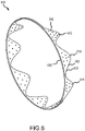
FIG. 6 illustrates a chevron ring, in accordance with various embodiments; and -
FIG. 7 illustrates a multi-piece chevron ring, in accordance with various embodiments. - The following detailed description of various embodiments herein makes reference to the accompanying drawings, which show various embodiments by way of illustration. While these various embodiments are described in sufficient detail to enable those skilled in the art to practice the disclosure, it should be understood that other embodiments may be realized and that changes may be made without departing from the scope of the disclosure. Thus, the detailed description herein is presented for purposes of illustration only and not of limitation. Furthermore, any reference to singular includes plural embodiments, and any reference to more than one component or step may include a singular embodiment or step. Also, any reference to attached, fixed, connected, or the like may include permanent, removable, temporary, partial, full or any other possible attachment option. Additionally, any reference to without contact (or similar phrases) may also include reduced contact or minimal contact. It should also be understood that unless specifically stated otherwise, references to "a," "an" or "the" may include one or more than one and that reference to an item in the singular may also include the item in the plural. Further, all ranges may include upper and lower values and all ranges and ratio limits disclosed herein may be combined.
- Referring now to the drawings,
FIG. 1 schematically illustrates agas turbine engine 20. Thegas turbine engine 20 is disclosed herein as a two-spool turbofan that generally incorporates afan section 22, acompressor section 24, acombustor section 26 and aturbine section 28. Thefan section 22 drives air along a bypass flow path B in a bypass duct defined within anacelle 15, while thecompressor section 24 drives air along a core flow path C for compression and communication into thecombustor section 26 and then expansion through theturbine section 28. Although depicted as a two-spool turbofan gas turbine engine in the disclosed non-limiting embodiment, the concepts described herein are not limited to use with two-spool turbofans as the teachings may be applied to other types of turbine engines. - The
gas turbine engine 20 generally includes alow speed spool 30 and ahigh speed spool 32 mounted for rotation about an engine central longitudinal axis A relative to an enginestatic structure 36 viaseveral bearing systems 38. Various bearing systems at various locations may alternatively or additionally be provided and the location of theseveral bearing systems 38 may be varied as appropriate to the application. Thelow speed spool 30 generally includes aninner shaft 40 that interconnects afan 42, alow pressure compressor 44 and alow pressure turbine 46. Theinner shaft 40 is connected to thefan 42 through a speed change mechanism, which in thisgas turbine engine 20 is illustrated as a fandrive gear system 48 configured to drive thefan 42 at a lower speed than that of thelow speed spool 30. Thehigh speed spool 32 includes anouter shaft 50 that interconnects ahigh pressure compressor 52 and ahigh pressure turbine 54. Acombustor 56 is arranged in thegas turbine engine 20 between thehigh pressure compressor 52 and thehigh pressure turbine 54. Amid-turbine frame 57 of the enginestatic structure 36 is arranged generally between thehigh pressure turbine 54 and thelow pressure turbine 46 and may includeairfoils 59 in the core flow path C for guiding the flow into thelow pressure turbine 46. Themid-turbine frame 57 further supports theseveral bearing systems 38 in theturbine section 28. Theinner shaft 40 and theouter shaft 50 are concentric and rotate via theseveral bearing systems 38 about the engine central longitudinal axis A, which is collinear with longitudinal axes of theinner shaft 40 and theouter shaft 50. - The air in the core flow path C is compressed by the
low pressure compressor 44 and then thehigh pressure compressor 52, mixed and burned with fuel in thecombustor 56, and then expanded over thehigh pressure turbine 54 and thelow pressure turbine 46. Thelow pressure turbine 46 and thehigh pressure turbine 54 rotationally drive respectively, thelow speed spool 30 and thehigh speed spool 32 in response to the expansion. It will be appreciated that each of the positions of thefan section 22, thecompressor section 24, thecombustor section 26, theturbine section 28, and the fandrive gear system 48 may be varied. For example, the fandrive gear system 48 may be located aft of thecombustor section 26 or even aft of theturbine section 28, and thefan section 22 may be positioned forward or aft of the location of the fandrive gear system 48. - The
compressor section 24, thecombustor section 26 and theturbine section 28 comprise a core engine arranged within acore nacelle 64. Atail cone 66 is arranged downstream from the core engine and is radially inward of thecore nacelle 64. A core engine exhaust E exits the core engine between thecore nacelle 64 and thetail cone 66. Afan nacelle 62 at least surrounds thecore nacelle 64. Thefan 42 is disposed inside thefan nacelle 62 upstream from the core engine andcore nacelle 64. Thefan nacelle 62 provides aninlet 63 that receives airflow into thegas turbine engine 20. The bypass flow path B exits between thefan nacelle 62 andcore nacelle 64. - A geared gas turbine engine has a unique noise signature that is not present in non-geared gas turbine engines. More specifically, unlike conventional two spool gas turbine engines in which the fan rotates at the same speed as the low pressure compressor and the low pressure turbine, the gear of the exemplary embodiments herein enables the fan to rotate slower while at the same time enabling the low pressure compressor and the low pressure turbine to rotate faster. Thus, the exhaust configuration is tuned to reduce the type of noise unique to a geared gas turbine engine, though the disclosure contemplates applicability to any type of gas turbine engine, including one or both of the core engine exhaust Ec and bypass flow path exhaust EB.
- Referring now to
FIGS. 2A, 2B and 2C , various configurations for both the core engine exhaust EC (about a tail cone, such as, for example, thetail cone 66 described above with reference toFIG. 1 ) and the bypass flow path exhaust EB are illustrated. Referring toFIG. 2A , for example, afan nacelle 621 exhibits afan nozzle 631 having a round exhaust profile, while acore nacelle 641 exhibits a core nozzle 651 having a plurality ofchevrons 70 spaced about its circumference. Referring toFIG. 2B , afan nacelle 622 exhibits afan nozzle 632 having a plurality ofchevrons 70 spaced about its circumference, while acore nacelle 642 exhibits a core nozzle 652 having a round exhaust profile. Referring toFIG. 2C , afan nacelle 623 exhibits afan nozzle 633 having a plurality ofchevrons 70 spaced about its circumference and acore nacelle 643 that also has a plurality ofchevrons 70 spaced about its circumference. Note that while the disclosure is directed primarily to various embodiments, represented byFIG. 2A , the disclosure is considered equally applicable to the various embodiments represented byFIGS. 2B and 2C . Note also that the term "chevron," as used herein, is intended to refer to a noise reduction feature positioned on or integrated into the core nozzle or the bypass nozzle. The chevrons are incorporated into the downstream exits of the nozzles to reduce noise and may comprise a variety of configurations, including triangular, circular, sinuous and elliptical shapes, among other shapes. Without loss of generality, this disclosure generally illustrates and describes sinuous shapes, but contemplates other shapes as well. - Referring now to
FIGS. 3A and 3B , perspective and cross sectional views of a nozzle assembly 300 (or an exhaust nozzle assembly) for a gas turbine engine are provided. In various embodiments, thenozzle assembly 300 includes atail cone 302, a fairing 304, afire seal 306, anattachment flange 308 and achevron ring 310, where thechevron ring 310 includes a chevron 312 (or a plurality of chevrons 314) extending from acore 316. Thecore 316 includes aninner skin 318 and anouter skin 320 configured to sandwich an interior that, in various embodiments, may include ahoneycomb structure 319 configured to suppress noise. In various embodiments, a fairingskin 321 covers thecore 316 and aerodynamically transitions into an upstream end of thechevron ring 310. As will be discussed further below, in various embodiments, thechevron ring 310 may be attached to thecore 316 using various techniques, including, without limitation, liquid interface diffusion bonding, welding, fasteners or combinations thereof. - Referring now to
FIGS. 4A, 4B ,4C, 4D and4E , various embodiments of achevron ring 410 and methods of attaching thechevron ring 410 to acore 416 to form anozzle assembly 400 are described. Referring, for example, toFIGS. 4A and 4B , perspective and cross-sectional views of thechevron ring 410 are provided. Thechevron ring 410 includes a chevron 412 (or a plurality of chevrons 414). Thechevron 412 includes adownstream periphery 422 that defines a sinuous shape and provides an outer border for a hollow portion 424 (or a partially hollow portion) which, as illustrated inFIG. 4B , spans from adownstream portion 432 to an upstream attachment portion 438 (or an attachment ring). Ashell portion 436 spans a surface area of thechevron 412 and provides a lower surface or a floor for thehollow portion 424. A trailing edge portion 430 (or the downstream portion 432) tracks thedownstream periphery 422 in the sinuous shape referred to above and includes adownstream step portion 434 configured to receive a trailing edge portion of a cover skin configured to cover thehollow portion 424. Similarly, theupstream attachment portion 438 includes anupstream step portion 435 configured to receive an upstream edge portion of the cover skin configured to cover thehollow portion 424. In various embodiments, thechevron 412 defines a nominal thickness at thedownstream portion 432 and thehollow portion 424 defines a depth of about twenty percent (20%) to about ninety percent (90%) of the nominal thickness, or, in various embodiments, a depth of about forty percent (40%) to about ninety percent (90%) of the nominal thickness, or, in various embodiments, a depth of about sixty percent (60%) to about ninety percent (90%) of the nominal thickness. Further, thechevron 412 defines a nominal surface area bounded by theupstream attachment portion 438 and thedownstream portion 432, and thehollow portion 424 defines a cutout surface area of about twenty percent (20%) to about ninety percent (90%) of the nominal surface area, or, in various embodiments, a cutout surface area of about forty percent (40%) to about ninety percent (90%) of the nominal surface area or, in various embodiments, a cutout surface area of about sixty percent (60%) to about ninety percent (90%) of the nominal surface area. - Referring more particularly to
FIGS. 4C, 4D and4E , and with continued reference toFIGS. 4A and 4B , various methods of attaching thechevron ring 410 to thecore 416 are described. Referring toFIG. 4C , for example, thechevron ring 410 having thehollow portion 424 is illustrated with acover skin 440 extending from thedownstream step portion 434 to theupstream step portion 435. In various embodiments, thecover skin 440 is secured via an adhesive, a weld or otherwise fastened to thedownstream step portion 434 and to theupstream step portion 435. Theupstream attachment portion 438 includes a radiallyinner flange 450 that is welded to acloseout seal 409 about the circumference of thechevron ring 410. In various embodiments, theupstream attachment portion 438 also includes a radiallyouter flange 452 that is welded to thecloseout seal 409. In various embodiments, a fairingskin 421 may be fastened via afastener 454, or via a plurality of fasteners spaced circumferentially about the radiallyouter flange 452. As further illustrated, thecloseout seal 409 is secured to thecore 416 via any suitable technique, such as, for example, an adhesive or other suitable fastener. - Referring now to
FIG. 4D , asimilar nozzle assembly 400 is illustrated, where thechevron 412 includes thehollow portion 424 bounded byshell portion 436 and thecover skin 440 extending from thedownstream step portion 434 to theupstream step portion 435. In various embodiments, theupstream attachment portion 438 is welded to apanel ring 460 at acircumferential face 462 that extends from a radiallyinner surface 463 to a radiallyouter surface 464 of theupstream attachment portion 438 and thepanel ring 460. In various embodiments, the welding at thecircumferential face 462 is accomplished via a rotary friction process, whereby the two surfaces meeting at thecircumferential face 462 are heated until they reach a plastic state and then forged together by an axial load, creating a welded joint (or a rotary friction weld) across thecircumferential face 462. - Referring now to
FIG. 4E , asimilar nozzle assembly 400 is illustrated, where thechevron 412 includes thehollow portion 424 bounded byshell portion 436 and thecover skin 440 extending from thedownstream step portion 434 to theupstream step portion 435. Theupstream attachment portion 438 includes a radiallyinner flange 450 that is fastened via afastener 458, or via a plurality of fasteners spaced circumferentially about the radiallyinner flange 450, to acloseout seal 409. In various embodiments, theupstream attachment portion 438 also includes a radiallyouter flange 452 that is similarly fastened to the fairingskin 421 via afastener 454, or via a plurality of fasteners spaced circumferentially about the radiallyouter flange 452. As further illustrated, thecloseout seal 409 is secured to thecore 416 via any suitable technique, such as, for example, an adhesive or other suitable fastener. - Referring now to
FIGS. 5A and5B , various embodiments of achevron ring 510 and methods of attaching thechevron ring 510 to acore 516 to form anozzle assembly 500 are described. Referring, for example, toFIG. 5A , a perspective view of thechevron ring 510 is provided. Thechevron ring 510 includes a chevron 512 (or a plurality of chevrons 514). Thechevron 512 includes adownstream periphery 522 that defines a sinuous shape and provides an outer border for ahollow portion 525 which, as illustrated inFIG. 5B , spans from adownstream portion 532 to anupstream attachment portion 538. Unlike thehollow portion 424 described above with reference toFIGS. 4A-4E , thehollow portion 525 is a fully hollow portion that extends completely through thechevron 512. A trailingedge portion 530 tracks thedownstream periphery 522 in the sinuous shape referred to above and includes a firstdownstream step portion 534 configured to receive a trailing edge portion of a cover skin configured to cover thehollow portion 525. Similarly, theupstream attachment portion 538 includes a firstupstream step portion 535 configured to receive an upstream edge portion of the cover skin configured to cover thehollow portion 525. - Referring more particularly to
FIG. 5B , and with continued reference toFIG. 5A , a method of attaching thechevron ring 510 to thecore 516 is described. In various embodiments, for example, thechevron ring 510 having thehollow portion 525 is illustrated with afirst cover skin 540 extending from the firstdownstream step portion 534 to the firstupstream step portion 535. In various embodiments, thefirst cover skin 540 is secured via an adhesive, a weld or otherwise fastened to the firstdownstream step portion 534 and to the firstupstream step portion 535. Thechevron ring 510 is illustrated with asecond cover skin 570 extending from a seconddownstream step portion 533 to a secondupstream step portion 537. In various embodiments, thesecond cover skin 570 is secured via an adhesive or otherwise welded or fastened to the seconddownstream step portion 533 and to the secondupstream step portion 537. As illustrated, thefirst cover skin 540 and thesecond cover skin 570 enclose thehollow portion 525. Theupstream attachment portion 538 includes a radiallyinner flange 550 that is fastened via a fastener 558, or via a plurality of fasteners spaced circumferentially about the radiallyinner flange 550, to acloseout seal 509. In various embodiments, theupstream attachment portion 538 also includes a radiallyouter flange 552 that is similarly fastened to afairing skin 521 via afastener 554, or via a plurality of fasteners spaced circumferentially about the radiallyouter flange 552. As further illustrated, thecloseout seal 509 is secured to thecore 516 via any suitable technique, such as, for example, an adhesive or other suitable fastener. WhileFIG. 5B includes a similar manner of attachment as described in reference toFIG. 4E , the disclosure is not limiting in this regard, and contemplates the manners of attachment described in reference toFIGS. 4C and 4D as well. - Referring now to
FIG. 6 , various embodiments of achevron ring 610 are described. Thechevron ring 610 includes a chevron 612 (or a plurality of chevrons 614). Thechevron 612 includes adownstream periphery 622 that defines a sinuous shape. Similar to the above description regarding thechevron ring 410 and thechevron ring 510, thechevron ring 610 spans from adownstream portion 632 to anupstream attachment portion 638. In contrast to thechevron ring 410 having the hollow portion 424 (or the partially hollow portion) or to thechevron ring 510 having the hollow portion 524 (or the fully hollow portion), thechevron ring 610 includes a plurality ofholes 670, each of which may be formed to extend partially through thechevron ring 610 or fully through thechevron ring 610. In various embodiments, each of the manners of attachment of thechevron ring 410 and thechevron ring 510 to, respectively, thecloseout seal 409 and thecloseout seal 509 and to thecore 416 and thecore 516 are contemplated for thechevron ring 610. Further, each of the manners of attachment of the cover skins (e.g., thecover skin 440 described with reference toFIGS. 4C-4E or one or both of thefirst cover skin 540 and thesecond cover skin 570 described with reference toFIG. 5B ) are contemplated by this disclosure as suitable for covering the plurality ofholes 670. Accordingly, those details are not repeated here. - Referring now to
FIG. 7 , various embodiments of a multi-piece-chevron ring 710 are described. Similar to the various embodiments above described, the multi-piece-chevron ring 710 includes a chevron 712 (or a plurality of chevrons 714). Thechevron 712 includes adownstream periphery 722 that defines a sinuous shape. Similar to the above description regarding thechevron ring 410, thechevron ring 510 and thechevron ring 610, the multi-piece-chevron ring 710 spans from adownstream portion 732 to anupstream attachment portion 738. In contrast to the chevron rings above described, however, the multi-piece-chevron ring 710 is fabricated from multiple segments, such as, for example, afirst segment 790 having afirst chevron 791 and asecond chevron 792 and asecond segment 793 having athird chevron 794 and afourth chevron 795. Note that each of the segments are identical in shape, meaning a single forging unit may be employed to fabricate the various segments. In various embodiments, the multi-piece-chevron ring 710 also includes apylon segment 780 configured for attachment proximate a pylon of an aircraft. In various embodiments, each of the configurations described above for thechevron ring 410 having the hollow portion 424 (or the partially hollow portion) and thechevron ring 510 having the hollow portion 524 (or the fully hollow portion) are contemplated as applicable to the multi-piece-chevron ring 710, and each of the manners of attachment of the cover skins (e.g., thecover skin 440 described with reference toFIGS. 4C-4E or one or both of thefirst cover skin 540 and thesecond cover skin 570 described with reference toFIG. 5B ) are contemplated as applicable to the multi-piece-chevron ring 710. Further, in various embodiments, each of the manners of attachment of thechevron ring 410 and thechevron ring 510 to, respectively, thecloseout seal 409 and thecloseout seal 509 and to thecore 416 and thecore 516 are contemplated as applicable for the multi-piece-chevron ring 710. Accordingly, those details are not repeated here. - The foregoing disclosure provides a chevron ring that is lightweight and relatively straightforward to manufacture. The various components of the chevron rings disclosed above may be fabricated (e.g., forged) from any high temperature capable material, such as, for example, titanium or various alloys of titanium (e.g., Ti-6-4). The resulting chevron rings exhibit a weight saving of more than fifty percent (50%) over their constant thickness counterparts (e.g., chevron rings having chevrons with no hollow portion). The resulting chevron rings are also readily amenable to attachment to core structures (e.g., via welding or fasteners) to provide finished engine components such as, for example, core engine exhaust nozzle structures or assembled gas turbine engine structures having the benefits described above.
- Benefits, other advantages, and solutions to problems have been described herein with regard to specific embodiments. Furthermore, the connecting lines shown in the various figures contained herein are intended to represent exemplary functional relationships and/or physical couplings between the various elements. It should be noted that many alternative or additional functional relationships or physical connections may be present in a practical system. However, the benefits, advantages, solutions to problems, and any elements that may cause any benefit, advantage, or solution to occur or become more pronounced are not to be construed as critical, required, or essential features or elements of the disclosure. The scope of the disclosure is accordingly to be limited by nothing other than the appended claims, in which reference to an element in the singular is not intended to mean "one and only one" unless explicitly so stated, but rather "one or more." Moreover, where a phrase similar to "at least one of A, B, or C" is used in the claims, it is intended that the phrase be interpreted to mean that A alone may be present in an embodiment, B alone may be present in an embodiment, C alone may be present in an embodiment, or that any combination of the elements A, B and C may be present in a single embodiment; for example, A and B, A and C, B and C, or A and B and C. Different cross-hatching is used throughout the figures to denote different parts but not necessarily to denote the same or different materials.
- Systems, methods and apparatus are provided herein. In the detailed description herein, references to "one embodiment," "an embodiment," "various embodiments," etc., indicate that the embodiment described may include a particular feature, structure, or characteristic, but every embodiment may not necessarily include the particular feature, structure, or characteristic. Moreover, such phrases are not necessarily referring to the same embodiment. Further, when a particular feature, structure, or characteristic is described in connection with an embodiment, it is submitted that it is within the knowledge of one skilled in the art to affect such feature, structure, or characteristic in connection with other embodiments whether or not explicitly described. After reading the description, it will be apparent to one skilled in the relevant art(s) how to implement the disclosure in alternative embodiments.
- Numbers, percentages, or other values stated herein are intended to include that value, and also other values that are about or approximately equal to the stated value, as would be appreciated by one of ordinary skill in the art encompassed by various embodiments of the present disclosure. A stated value should therefore be interpreted broadly enough to encompass values that are at least close enough to the stated value to perform a desired function or achieve a desired result. The stated values include at least the variation to be expected in a suitable industrial process, and may include values that are within 10%, within 5%, within 1%, within 0.1%, or within 0.01% of a stated value. Additionally, the terms "substantially," "about" or "approximately" as used herein represent an amount close to the stated amount that still performs a desired function or achieves a desired result. For example, the term "substantially," "about" or "approximately" may refer to an amount that is within 10% of, within 5% of, within 1% of, within 0.1% of, and within 0.01% of a stated amount or value.
- Furthermore, no element, component, or method step in the present disclosure is intended to be dedicated to the public regardless of whether the element, component, or method step is explicitly recited in the claims. As used herein, the terms "comprises," "comprising," or any other variation thereof, are intended to cover a non-exclusive inclusion, such that a process, method, article, or apparatus that comprises a list of elements does not include only those elements but may include other elements not expressly listed or inherent to such process, method, article, or apparatus.
- Finally, it should be understood that any of the above described concepts can be used alone or in combination with any or all of the other above described concepts. Although various embodiments have been disclosed and described, one of ordinary skill in this art would recognize that certain modifications would come within the scope of this disclosure. Accordingly, the description is not intended to be exhaustive or to limit the principles described or illustrated herein to any precise form. Many modifications and variations are possible in light of the above teaching.
Claims (11)
- A chevron ring (310; 410; 510; 610; 710), comprising:an attachment ring (438; 538; 638; 738); anda chevron (312; 412; 512; 612; 712), the chevron (312; 412; 512; 612; 712) connected to and extending downstream of the attachment ring (438; 538; 638; 738) and having a trailing edge portion (430; 530), the chevron (312; 412; 512; 612; 712) defining a hollow portion (424; 525; 670) between the attachment ring (438; 538; 638; 738) and the trailing edge portion (430; 530).
- The chevron ring (310; 410; 510; 710) of claim 1, wherein the chevron ring (310; 410; 510; 710) defines a nominal surface area bounded by the attachment ring (438; 538; 738) and the trailing edge portion (430; 530) and the hollow portion (424; 525) defines a cutout surface area of between twenty percent and ninety percent of the nominal surface area.
- The chevron ring (310; 410; 610; 710) of claim 1 or 2, wherein the chevron ring (310; 410; 610; 710) defines a nominal thickness at the trailing edge portion (430) and the hollow portion (424; 670) defines a depth of between twenty percent and ninety percent of the nominal thickness.
- The chevron ring (310; 510; 610; 710) of claim 1 or 2, wherein the hollow portion (525; 670) extends completely through a nominal thickness of the chevron ring (310; 510; 610; 710).
- The chevron ring (310; 410; 510; 610; 710) of any preceding claim, further comprising a cover skin (440; 540, 570) configured to cover the hollow portion.
- The chevron ring (310; 510; 610; 710) of any of claims 1 to 4, further comprising a first cover skin (540) configured to cover a radially outer side of the hollow portion (525; 670) and a second cover skin (570) configured to cover a radially inner side of the hollow portion (525; 670).
- The chevron ring (310; 610) of any preceding claim, wherein the hollow portion (670) comprises a plurality of holes (670).
- The chevron ring (710) of any preceding claim, wherein the chevron ring (710) comprises a multi-piece-chevron ring (710).
- An exhaust nozzle (300), comprising:a core (316; 416; 516); andthe chevron ring (310; 410; 510; 610; 710) of any preceding claim attached to the core (316; 416; 516).
- The exhaust nozzle (300) of claim 9, wherein the attachment ring (438; 538; 638; 738) is attached to the core (316; 416; 516) via at least one of a fastener or a weld.
- The exhaust nozzle (300) of claim 9 or 10, wherein the attachment ring (438; 538; 638; 738) is attached to the core (316; 416; 516) via a rotary friction weld.
Applications Claiming Priority (1)
| Application Number | Priority Date | Filing Date | Title |
|---|---|---|---|
| US17/129,612 US12292014B2 (en) | 2020-12-21 | 2020-12-21 | Gas turbine engine exhaust chevrons |
Publications (1)
| Publication Number | Publication Date |
|---|---|
| EP4015812A1 true EP4015812A1 (en) | 2022-06-22 |
Family
ID=78957669
Family Applications (1)
| Application Number | Title | Priority Date | Filing Date |
|---|---|---|---|
| EP21216217.6A Pending EP4015812A1 (en) | 2020-12-21 | 2021-12-21 | Gas turbine engine exhaust chevrons |
Country Status (2)
| Country | Link |
|---|---|
| US (1) | US12292014B2 (en) |
| EP (1) | EP4015812A1 (en) |
Cited By (2)
| Publication number | Priority date | Publication date | Assignee | Title |
|---|---|---|---|---|
| DE102023134471A1 (en) * | 2023-12-08 | 2025-06-12 | Ebm-Papst St. Georgen Gmbh & Co. Kg | Flow guide device and fan with a flow guide device |
| EP4520947A3 (en) * | 2023-09-11 | 2025-06-25 | Rohr, Inc. | Exhaust nozzle assembly for aircraft propulsion system |
Families Citing this family (1)
| Publication number | Priority date | Publication date | Assignee | Title |
|---|---|---|---|---|
| US12623785B2 (en) * | 2024-10-01 | 2026-05-12 | Rtx Corporation | Open rotor propulsion system with exhaust mixer(s) |
Citations (4)
| Publication number | Priority date | Publication date | Assignee | Title |
|---|---|---|---|---|
| US20050229585A1 (en) * | 2001-03-03 | 2005-10-20 | Webster John R | Gas turbine engine exhaust nozzle |
| US20090019857A1 (en) * | 2007-07-18 | 2009-01-22 | Rudolph Morris Tisdale | Modular chevron exhaust nozzle |
| US20160138424A1 (en) * | 2014-11-19 | 2016-05-19 | Rohr, Inc. | Boot for repair of chevron on nacelle |
| US20160138416A1 (en) * | 2006-10-12 | 2016-05-19 | United Technologies Corporation | Variable fan nozzle using shape memory material |
Family Cites Families (12)
| Publication number | Priority date | Publication date | Assignee | Title |
|---|---|---|---|---|
| GB2289921A (en) * | 1994-06-03 | 1995-12-06 | A E Harris Limited | Nozzle for turbofan aeroengines |
| US6532729B2 (en) | 2001-05-31 | 2003-03-18 | General Electric Company | Shelf truncated chevron exhaust nozzle for reduction of exhaust noise and infrared (IR) signature |
| US7305817B2 (en) | 2004-02-09 | 2007-12-11 | General Electric Company | Sinuous chevron exhaust nozzle |
| FR2890696B1 (en) * | 2005-09-12 | 2010-09-17 | Airbus France | TURBOMOTEUR WITH ATTENUATED JET NOISE |
| RU2310766C1 (en) * | 2006-02-06 | 2007-11-20 | Открытое акционерное общество "Авиадвигатель" | Herringrone reaction nozzle of gas-turbine engine |
| DE102006019299B3 (en) | 2006-04-26 | 2007-11-08 | Deutsches Zentrum für Luft- und Raumfahrt e.V. | Aircraft turbofan jet engine, with a primary and a ring-shaped side jet, has an adjustment mechanism of rings to reduce noise emissions on take-off |
| US7966826B2 (en) * | 2007-02-14 | 2011-06-28 | The Boeing Company | Systems and methods for reducing noise from jet engine exhaust |
| US7963099B2 (en) * | 2007-05-21 | 2011-06-21 | General Electric Company | Fluted chevron exhaust nozzle |
| FR2920036B1 (en) * | 2007-08-14 | 2013-11-15 | Airbus France | ANTI-NOISE CHEVRONS FOR TUYERE |
| US20100193605A1 (en) | 2009-01-30 | 2010-08-05 | Michael Robert Johnson | Thermally balanced aero structures |
| US8356468B2 (en) | 2009-06-12 | 2013-01-22 | The Boeing Company | Gas turbine engine nozzle configurations |
| EP3161271A1 (en) | 2014-06-30 | 2017-05-03 | Rudolf Ganz | Chevron nozzle |
-
2020
- 2020-12-21 US US17/129,612 patent/US12292014B2/en active Active
-
2021
- 2021-12-21 EP EP21216217.6A patent/EP4015812A1/en active Pending
Patent Citations (4)
| Publication number | Priority date | Publication date | Assignee | Title |
|---|---|---|---|---|
| US20050229585A1 (en) * | 2001-03-03 | 2005-10-20 | Webster John R | Gas turbine engine exhaust nozzle |
| US20160138416A1 (en) * | 2006-10-12 | 2016-05-19 | United Technologies Corporation | Variable fan nozzle using shape memory material |
| US20090019857A1 (en) * | 2007-07-18 | 2009-01-22 | Rudolph Morris Tisdale | Modular chevron exhaust nozzle |
| US20160138424A1 (en) * | 2014-11-19 | 2016-05-19 | Rohr, Inc. | Boot for repair of chevron on nacelle |
Cited By (5)
| Publication number | Priority date | Publication date | Assignee | Title |
|---|---|---|---|---|
| EP4520947A3 (en) * | 2023-09-11 | 2025-06-25 | Rohr, Inc. | Exhaust nozzle assembly for aircraft propulsion system |
| EP4520946A3 (en) * | 2023-09-11 | 2025-06-25 | Rohr, Inc. | Exhaust nozzle assembly for aircraft propulsion system |
| EP4520945A3 (en) * | 2023-09-11 | 2025-07-09 | Rohr, Inc. | Exhaust nozzle assembly for aircraft propulsion system |
| DE102023134471A1 (en) * | 2023-12-08 | 2025-06-12 | Ebm-Papst St. Georgen Gmbh & Co. Kg | Flow guide device and fan with a flow guide device |
| WO2025119917A1 (en) | 2023-12-08 | 2025-06-12 | Ebm-Papst St. Georgen Gmbh & Co. Kg | Flow guide device and fan having a flow guide device |
Also Published As
| Publication number | Publication date |
|---|---|
| US20220195960A1 (en) | 2022-06-23 |
| US12292014B2 (en) | 2025-05-06 |
Similar Documents
| Publication | Publication Date | Title |
|---|---|---|
| US9033654B2 (en) | Variable geometry vane system for gas turbine engines | |
| US8177513B2 (en) | Method and apparatus for a structural outlet guide vane | |
| US10920672B2 (en) | Gas turbine | |
| EP2805022B1 (en) | Gas turbine bypass vane system, gas turbine engine and method for manufacturing a bypass vane stage | |
| US12134996B2 (en) | Acoustic liner and gas turbine engine with such acoustic liner | |
| US20180328214A1 (en) | Alternative w-seal groove arrangement | |
| EP2880295B1 (en) | Retrofitable auxiliary inlet scoop | |
| US12292014B2 (en) | Gas turbine engine exhaust chevrons | |
| EP3252271B1 (en) | Blade assembly, corresponding fan section and gas turbine engine | |
| US12286905B2 (en) | Rotor assembly for gas turbine engines | |
| US12535007B2 (en) | Cover plate connections for a hollow fan blade | |
| EP3540312A1 (en) | Combustor liner panel with castellated rail | |
| EP3129630B1 (en) | Variable profile cascade | |
| US20250214712A1 (en) | Acoustic panel for an aircraft propulsion system | |
| US20250214713A1 (en) | Acoustic panel for an aircraft propulsion system | |
| EP2472070B1 (en) | Methods of manufacturing a gas turbine engine case and corresponding case | |
| US20220063823A1 (en) | Nacelle | |
| US20190390688A1 (en) | Gas turbine engine airfoil | |
| US20210231020A1 (en) | Hybrid airfoil for gas turbine engines | |
| US10746041B2 (en) | Shroud and shroud assembly process for variable vane assemblies | |
| US20160237850A1 (en) | Systems and methods for vane cooling | |
| EP3677837B1 (en) | Combustor cooling panel with flow guide | |
| CA2697292C (en) | Method and apparatus for a structural outlet guide vane | |
| EP3434596B1 (en) | Nacelle | |
| EP4579651A1 (en) | Acoustic panel for an aircraft propulsion system |
Legal Events
| Date | Code | Title | Description |
|---|---|---|---|
| PUAI | Public reference made under article 153(3) epc to a published international application that has entered the european phase |
Free format text: ORIGINAL CODE: 0009012 |
|
| STAA | Information on the status of an ep patent application or granted ep patent |
Free format text: STATUS: THE APPLICATION HAS BEEN PUBLISHED |
|
| AK | Designated contracting states |
Kind code of ref document: A1 Designated state(s): AL AT BE BG CH CY CZ DE DK EE ES FI FR GB GR HR HU IE IS IT LI LT LU LV MC MK MT NL NO PL PT RO RS SE SI SK SM TR |
|
| STAA | Information on the status of an ep patent application or granted ep patent |
Free format text: STATUS: REQUEST FOR EXAMINATION WAS MADE |
|
| 17P | Request for examination filed |
Effective date: 20221222 |
|
| RBV | Designated contracting states (corrected) |
Designated state(s): AL AT BE BG CH CY CZ DE DK EE ES FI FR GB GR HR HU IE IS IT LI LT LU LV MC MK MT NL NO PL PT RO RS SE SI SK SM TR |
|
| STAA | Information on the status of an ep patent application or granted ep patent |
Free format text: STATUS: EXAMINATION IS IN PROGRESS |
|
| 17Q | First examination report despatched |
Effective date: 20240902 |