EP4015803B1 - Quick access engine rotator pad - Google Patents
Quick access engine rotator pad Download PDFInfo
- Publication number
- EP4015803B1 EP4015803B1 EP21215662.4A EP21215662A EP4015803B1 EP 4015803 B1 EP4015803 B1 EP 4015803B1 EP 21215662 A EP21215662 A EP 21215662A EP 4015803 B1 EP4015803 B1 EP 4015803B1
- Authority
- EP
- European Patent Office
- Prior art keywords
- shaft
- housing
- motor
- drive shaft
- hand tool
- Prior art date
- Legal status (The legal status is an assumption and is not a legal conclusion. Google has not performed a legal analysis and makes no representation as to the accuracy of the status listed.)
- Active
Links
Images



Classifications
-
- F—MECHANICAL ENGINEERING; LIGHTING; HEATING; WEAPONS; BLASTING
- F02—COMBUSTION ENGINES; HOT-GAS OR COMBUSTION-PRODUCT ENGINE PLANTS
- F02C—GAS-TURBINE PLANTS; AIR INTAKES FOR JET-PROPULSION PLANTS; CONTROLLING FUEL SUPPLY IN AIR-BREATHING JET-PROPULSION PLANTS
- F02C7/00—Features, components parts, details or accessories, not provided for in, or of interest apart form groups F02C1/00 - F02C6/00; Air intakes for jet-propulsion plants
- F02C7/32—Arrangement, mounting, or driving, of auxiliaries
-
- F—MECHANICAL ENGINEERING; LIGHTING; HEATING; WEAPONS; BLASTING
- F01—MACHINES OR ENGINES IN GENERAL; ENGINE PLANTS IN GENERAL; STEAM ENGINES
- F01D—NON-POSITIVE DISPLACEMENT MACHINES OR ENGINES, e.g. STEAM TURBINES
- F01D25/00—Component parts, details, or accessories, not provided for in, or of interest apart from, other groups
- F01D25/32—Collecting of condensation water; Drainage ; Removing solid particles
-
- F—MECHANICAL ENGINEERING; LIGHTING; HEATING; WEAPONS; BLASTING
- F01—MACHINES OR ENGINES IN GENERAL; ENGINE PLANTS IN GENERAL; STEAM ENGINES
- F01D—NON-POSITIVE DISPLACEMENT MACHINES OR ENGINES, e.g. STEAM TURBINES
- F01D25/00—Component parts, details, or accessories, not provided for in, or of interest apart from, other groups
- F01D25/34—Turning or inching gear
-
- F—MECHANICAL ENGINEERING; LIGHTING; HEATING; WEAPONS; BLASTING
- F01—MACHINES OR ENGINES IN GENERAL; ENGINE PLANTS IN GENERAL; STEAM ENGINES
- F01D—NON-POSITIVE DISPLACEMENT MACHINES OR ENGINES, e.g. STEAM TURBINES
- F01D5/00—Blades; Blade-carrying members; Heating, heat-insulating, cooling or antivibration means on the blades or the members
- F01D5/005—Repairing methods or devices
-
- F—MECHANICAL ENGINEERING; LIGHTING; HEATING; WEAPONS; BLASTING
- F02—COMBUSTION ENGINES; HOT-GAS OR COMBUSTION-PRODUCT ENGINE PLANTS
- F02C—GAS-TURBINE PLANTS; AIR INTAKES FOR JET-PROPULSION PLANTS; CONTROLLING FUEL SUPPLY IN AIR-BREATHING JET-PROPULSION PLANTS
- F02C7/00—Features, components parts, details or accessories, not provided for in, or of interest apart form groups F02C1/00 - F02C6/00; Air intakes for jet-propulsion plants
- F02C7/06—Arrangements of bearings; Lubricating
-
- F—MECHANICAL ENGINEERING; LIGHTING; HEATING; WEAPONS; BLASTING
- F02—COMBUSTION ENGINES; HOT-GAS OR COMBUSTION-PRODUCT ENGINE PLANTS
- F02C—GAS-TURBINE PLANTS; AIR INTAKES FOR JET-PROPULSION PLANTS; CONTROLLING FUEL SUPPLY IN AIR-BREATHING JET-PROPULSION PLANTS
- F02C7/00—Features, components parts, details or accessories, not provided for in, or of interest apart form groups F02C1/00 - F02C6/00; Air intakes for jet-propulsion plants
- F02C7/22—Fuel supply systems
-
- F—MECHANICAL ENGINEERING; LIGHTING; HEATING; WEAPONS; BLASTING
- F02—COMBUSTION ENGINES; HOT-GAS OR COMBUSTION-PRODUCT ENGINE PLANTS
- F02C—GAS-TURBINE PLANTS; AIR INTAKES FOR JET-PROPULSION PLANTS; CONTROLLING FUEL SUPPLY IN AIR-BREATHING JET-PROPULSION PLANTS
- F02C7/00—Features, components parts, details or accessories, not provided for in, or of interest apart form groups F02C1/00 - F02C6/00; Air intakes for jet-propulsion plants
- F02C7/26—Starting; Ignition
- F02C7/268—Starting drives for the rotor, acting directly on the rotor of the gas turbine to be started
- F02C7/275—Mechanical drives
-
- F—MECHANICAL ENGINEERING; LIGHTING; HEATING; WEAPONS; BLASTING
- F02—COMBUSTION ENGINES; HOT-GAS OR COMBUSTION-PRODUCT ENGINE PLANTS
- F02C—GAS-TURBINE PLANTS; AIR INTAKES FOR JET-PROPULSION PLANTS; CONTROLLING FUEL SUPPLY IN AIR-BREATHING JET-PROPULSION PLANTS
- F02C7/00—Features, components parts, details or accessories, not provided for in, or of interest apart form groups F02C1/00 - F02C6/00; Air intakes for jet-propulsion plants
- F02C7/28—Arrangement of seals
-
- F—MECHANICAL ENGINEERING; LIGHTING; HEATING; WEAPONS; BLASTING
- F05—INDEXING SCHEMES RELATING TO ENGINES OR PUMPS IN VARIOUS SUBCLASSES OF CLASSES F01-F04
- F05D—INDEXING SCHEME FOR ASPECTS RELATING TO NON-POSITIVE-DISPLACEMENT MACHINES OR ENGINES, GAS-TURBINES OR JET-PROPULSION PLANTS
- F05D2230/00—Manufacture
- F05D2230/72—Maintenance
-
- F—MECHANICAL ENGINEERING; LIGHTING; HEATING; WEAPONS; BLASTING
- F05—INDEXING SCHEMES RELATING TO ENGINES OR PUMPS IN VARIOUS SUBCLASSES OF CLASSES F01-F04
- F05D—INDEXING SCHEME FOR ASPECTS RELATING TO NON-POSITIVE-DISPLACEMENT MACHINES OR ENGINES, GAS-TURBINES OR JET-PROPULSION PLANTS
- F05D2230/00—Manufacture
- F05D2230/80—Repairing, retrofitting or upgrading methods
-
- F—MECHANICAL ENGINEERING; LIGHTING; HEATING; WEAPONS; BLASTING
- F05—INDEXING SCHEMES RELATING TO ENGINES OR PUMPS IN VARIOUS SUBCLASSES OF CLASSES F01-F04
- F05D—INDEXING SCHEME FOR ASPECTS RELATING TO NON-POSITIVE-DISPLACEMENT MACHINES OR ENGINES, GAS-TURBINES OR JET-PROPULSION PLANTS
- F05D2240/00—Components
- F05D2240/50—Bearings
-
- F—MECHANICAL ENGINEERING; LIGHTING; HEATING; WEAPONS; BLASTING
- F05—INDEXING SCHEMES RELATING TO ENGINES OR PUMPS IN VARIOUS SUBCLASSES OF CLASSES F01-F04
- F05D—INDEXING SCHEME FOR ASPECTS RELATING TO NON-POSITIVE-DISPLACEMENT MACHINES OR ENGINES, GAS-TURBINES OR JET-PROPULSION PLANTS
- F05D2240/00—Components
- F05D2240/55—Seals
-
- F—MECHANICAL ENGINEERING; LIGHTING; HEATING; WEAPONS; BLASTING
- F05—INDEXING SCHEMES RELATING TO ENGINES OR PUMPS IN VARIOUS SUBCLASSES OF CLASSES F01-F04
- F05D—INDEXING SCHEME FOR ASPECTS RELATING TO NON-POSITIVE-DISPLACEMENT MACHINES OR ENGINES, GAS-TURBINES OR JET-PROPULSION PLANTS
- F05D2240/00—Components
- F05D2240/60—Shafts
-
- F—MECHANICAL ENGINEERING; LIGHTING; HEATING; WEAPONS; BLASTING
- F05—INDEXING SCHEMES RELATING TO ENGINES OR PUMPS IN VARIOUS SUBCLASSES OF CLASSES F01-F04
- F05D—INDEXING SCHEME FOR ASPECTS RELATING TO NON-POSITIVE-DISPLACEMENT MACHINES OR ENGINES, GAS-TURBINES OR JET-PROPULSION PLANTS
- F05D2260/00—Function
- F05D2260/30—Retaining components in desired mutual position
- F05D2260/38—Retaining components in desired mutual position by a spring, i.e. spring loaded or biased towards a certain position
-
- F—MECHANICAL ENGINEERING; LIGHTING; HEATING; WEAPONS; BLASTING
- F05—INDEXING SCHEMES RELATING TO ENGINES OR PUMPS IN VARIOUS SUBCLASSES OF CLASSES F01-F04
- F05D—INDEXING SCHEME FOR ASPECTS RELATING TO NON-POSITIVE-DISPLACEMENT MACHINES OR ENGINES, GAS-TURBINES OR JET-PROPULSION PLANTS
- F05D2260/00—Function
- F05D2260/40—Transmission of power
- F05D2260/403—Transmission of power through the shape of the drive components
- F05D2260/4031—Transmission of power through the shape of the drive components as in toothed gearing
-
- F—MECHANICAL ENGINEERING; LIGHTING; HEATING; WEAPONS; BLASTING
- F05—INDEXING SCHEMES RELATING TO ENGINES OR PUMPS IN VARIOUS SUBCLASSES OF CLASSES F01-F04
- F05D—INDEXING SCHEME FOR ASPECTS RELATING TO NON-POSITIVE-DISPLACEMENT MACHINES OR ENGINES, GAS-TURBINES OR JET-PROPULSION PLANTS
- F05D2260/00—Function
- F05D2260/83—Testing, e.g. methods, components or tools therefor
-
- F—MECHANICAL ENGINEERING; LIGHTING; HEATING; WEAPONS; BLASTING
- F05—INDEXING SCHEMES RELATING TO ENGINES OR PUMPS IN VARIOUS SUBCLASSES OF CLASSES F01-F04
- F05D—INDEXING SCHEME FOR ASPECTS RELATING TO NON-POSITIVE-DISPLACEMENT MACHINES OR ENGINES, GAS-TURBINES OR JET-PROPULSION PLANTS
- F05D2260/00—Function
- F05D2260/98—Lubrication
Definitions
- the present invention relates to devices facilitating manual rotation of a component and, in particular, to gearboxes incorporating rotator features enabling manual rotation of components rotationally coupled to the gearbox, for example, a gas turbine engine rotor.
- Modem gas turbine engines include rotator features to enable manual rotation of one or more rotors of the gas turbine engine during engine maintenance and inspection.
- a rotator will be located on an idler gear of the accessory gearbox known to drive various components necessary for proper operation of the gas turbine engine, which may include a fuel pump, a lubricating oil pump, a hydraulic pump, an air turbine starter, an electric generator, and an engine starter, among other possible engine accessory components. Locating the rotator along with the driven engine accessories requires components along the load path between the gas turbine rotor and the rotator location to accommodate loads associated with engine operation as well as relatively higher loads associated with manual rotation of a gas turbine engine rotor. Further, access to the rotator often requires removal of an access cover on the accessory gearbox.
- EP0754838A1 , EP2415974A2 , EP2602442A1 , US6382909B1 and US2010/189548A1 relate to assemblies for gas turbine engines.
- An exemplary rotator assembly of the present invention as defined in claim 1 is provided.
- a rotator for rotating a gas turbine engine rotor without the assistance of the engine such as manual rotation of the gas turbine engine rotor for maintenance and inspection operations By configuring the rotator to be selectively engageable to an input shaft of a transmission coupling the engine to an accessory gearbox rather than a component of the gearbox itself, the size and weight of many of the accessory gearbox components driving various engine accessories can be reduced as operational load path is restored, and rotator operation does not become a sizing constraint.
- a seal cap encircling a drive end of the rotator shaft isolates and protects the accessory gearbox and transmission interiors without requiring removal and reinstallation of an access cover while facilitating access to the drive end of the rotator auxiliary shaft.
- motor and/or hand tool mounting provisions can be added to an exterior of accessory gearbox transmission and the drive end of such device configured to displace the rotator shaft into engagement with a shaft of the accessory gearbox transmission upon installation of the motor or hand tool.
- the rotator shaft can be spring-loaded, facilitating automatic disengagement of the rotator shaft from the transmission shaft via a spring-generated restoring force acting on the rotator shaft after removal of the motor or hand tool.
- features of the disclosed rotator can be applied to a device for manual rotation of aircraft control surfaces or other aircraft actuation mechanisms. More generally, other applications are conceivable including manual rotation of industrial gas turbine engines, other turbomachines, or other industrial machine components.
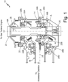
- FIG. 1 is a partial cross-sectional view of accessory gearbox 10 including transmission 12 rotationally coupling a gas turbine engine rotor to one or more engine accessories.
- Transmission 12 includes housing 14 enclosing input shaft 16 and output shaft 18.
- Input shaft 16 extends along axis 19 from engine-side end 16A, where input shaft 16 rotationally couples to a shaft of a gas turbine engine, to auxiliary-side end 16B, where input shaft 16 selectively couples to rotator 20. Between engine-side end 16A and auxiliary-side end 16B, input shaft 16 rotationally couples to output shaft 18 at gearing 22.
- Output shaft 18 extends along axis 24 from gearing 22 to accessory gearbox 10, where rotation of output shaft 18 drives one or more engine accessories which can include a fuel pump, a lubricating oil pump, a hydraulic pump, an air turbine starter, an electric generator, and an engine starter, among other possible engine accessory components.
- engine accessories can include a fuel pump, a lubricating oil pump, a hydraulic pump, an air turbine starter, an electric generator, and an engine starter, among other possible engine accessory components.
- input shaft 16 is perpendicular to output shaft 18 in the embodiment depicted by FIG. 1 such that axes 19 and 24 are coplanar.
- input shaft 16 can be configured in other orientations relative to output shaft 18 compatible with the gas turbine engine application.
- axis 19 of input shaft 16 can be perpendicular to axis 24 of output shaft 18 without being coplanar, such as when axis 19 and axis 24 extend along mutually orthogonal directions.
- input shaft 16 can extend along an oblique direction relative to output shaft 18, whether axes 19 and 24 are coplanar or not.
- axis 19 of input shaft 16 and axis 24 of output shaft 18 can be offset and parallel.
- gearing 22 can be selected to accommodate the relative orientations of input shaft 16 and output shaft 18 as well as to accommodate the mechanical design of transmission 12.
- gearing 22 includes intermeshing bevel gears 22A and 22B with straight or spiral profile gear teeth.
- Bevel gear 22A rotates with input shaft 16 while bevel gear 22B rotates with output shaft 18.
- Each of bevel gears 22A and 22B can be integrally manufactured with, joined to, or otherwise mechanically attached to respective shafts 16 and 18.
- gearing 22 can take other potential configurations such as a spur gear pair, a spur gear and worm gear pair, or a spline coupling, among other possible configurations.
- input shaft 16 includes spline 26, or other mechanical coupling for connecting input shaft 16 to a drive shaft of the gas turbine engine.
- input shaft 16 can be rotationally coupled to an outer end of radial drive shaft 23 (sometimes referred to as a tower shaft) relative to a centerline of the gas turbine engine.
- radial drive shaft 23 rotationally couples to a turbine shaft or a compressor shaft of the gas turbine engine.
- energy extracted by the turbine drives rotation of the turbine shaft, the compressor shaft, and the radial drive shaft, which in turn drives accessory gearbox 10 via input shaft 16, output shaft 18, and gearing 22.
- rotator 20 can selectively engage auxiliary-side end 16B of input shaft 16 to manually rotate the gas turbine engine rotor facilitating maintenance and/or inspection of the gas turbine engine.
- Input shaft 16 and output shaft 18 are laterally supported within housing 14 by one or more bearings 29, the number and position of each bearing determined based on the specific configuration of transmission 12 as well as the load and stiffness requirements for transmission 12, accessory gearbox 10, and the gas turbine engine.
- bearings 29A, 29B, and 29C laterally support input shaft 16.
- Bearing 29A supports input shaft 16 at a location between engine-side end 16A and gearing 22 while bearings 29B and 29C are adjacent to each other and located between gearing 22 and auxiliary-side end 16B along shaft 16.
- bearings 29D and 29E laterally support output shaft 18 adjacent to gearing 22.
- the opposing side of output shaft 18 can be supported by another bearing and/or a coupling (not shown) of accessory gearbox 10.
- FIGs. 2A and 2B are enlarged views of region A from FIG. 1 depicting features of rotator 20 and associated components in greater detail.
- FIG. 2A depicts rotator 20 disengaged from input shaft 16
- FIG. 2B shows rotator 20 engaged to input shaft 16. All components of rotator 20 are installed into bore 28 of housing 14 without requiring a cover to shield rotator 20 and/or internal components of accessory gearbox 10 and transmission 12 internal to housing 14.
- Rotator 20 includes auxiliary shaft 30 accessible through bore 28 of housing 14.
- Auxiliary shaft 30 extends from outboard end 30A to inboard end 30B along axis 31.
- One or more bearings 32 or bushings 33 laterally support auxiliary shaft 30 within bore 28.
- bearings 32A and 32B form a duplex bearing laterally supporting auxiliary shaft 30.
- bushings 33A and 33B can be used to provide lateral support of auxiliary shaft 30.
- Restraint of auxiliary shaft 30 along axis 31 is provided by spring 34 concentrically positioned about auxiliary shaft 30 and, at opposite ends of spring 34, engaging lip 36 of housing 14 and thrust washer 38, which in turn, abuts thrust plate 40 manufactured integrally with or otherwise mechanically attached to auxiliary shaft 30.
- spring 34 is at least partially compressed to bias auxiliary shaft 30 towards an exterior of housing 14.
- auxiliary shaft 30 includes rotational coupling 42 for engaging coupling 44 at auxiliary-side end 16B of input shaft 16.
- coupling 42 can be a spline along an outer diameter of auxiliary shaft 30 for engaging a corresponding spline formed along an inner diameter surface of input shaft 16.
- coupling 42 can be a key drive formed by one or more square or rectangular cross-section keys seated into auxiliary shaft 30, and coupling 44 is a corresponding key socket formed by a complimentary keyway of input shaft 16.
- Seal cap 46 is an annular body in which radially outer surface 46A engages bore 28 and radially inner surface 46B guides auxiliary shaft 30 along axis 31. Engagement of seal cap 46 can be achieved by providing an interference or location fit between outer surface 46A and bore 28, restraining seal cap 46 axially and laterally with respect to axis 31 and housing 14. In other embodiments, seal cap 46 can be retained within bore 28 using one or more snap rings. Further, seal cap 46 abuts bearing 32A and encloses bore 28 without obstructing access to outboard end 30A of auxiliary shaft 30, which is equipped with socket 48 for facilitating connection to a motor and/or a hand tool, manually turning auxiliary shaft 30, input shaft 16, and thereby rotating the gas turbine engine rotor and accessory gearbox components.
- Outer seal groove 50 extends into seal cap 46 and circumferentially along outer surface 46A of seal cap 46 to house static seal 52
- inner seal groove 54 extends into seal cap 46 and circumferentially along inner surface 46B of seal cap 46 to house sliding seal 56.
- static seal 52 is an o-ring
- sliding seal 56 is a lip seal, although different static and sliding seal configurations can be used in other embodiments.
- drive end 58 of motor 60 or hand tool 62 is inserted into socket 48 of auxiliary shaft 30.
- Drive end 58 can be a square driver and socket 48 can be a square socket.
- socket 48 has square geometry common to both motor 60 and hand tool 62 driven ends 58, such as a standard socket and driver size typical for hand tools.
- other drivers and socket combinations can be used including custom or standard hexagonal or other polygonal driver and socket combinations.
- motor 60 can be attached to housing 14 using bolt pattern 64, which can be configured as any suitable circumferentially spaced pattern of blind, threaded holes.
- motor 60 can be attached to housing 14 by a twist lock whereby a portion of motor 60 inserts into a cavity defined by housing 14 and is trapped in place following a twisting action of motor attachment.
- drive end 58 displaces auxiliary shaft 30 along axis 31 and compresses spring 34 causing inboard end 30B of auxiliary shaft 30 to engage corresponding features on auxiliary-side end 16B of input shaft 16 as shown in FIG. 2B .
- length LT between mounting flange 66 and a distal end of drive end 58 can be equal to distance RS between an exterior of housing 14 and a bottom of socket 48 plus engagement distance ED necessary to rotationally couple to input shaft 16 between end 30B of auxiliary shaft 30 and auxiliary-side end 16B of input shaft 16.
- mating features of couplings 42 and 44 can be equipped with lead-in features that promote angular alignment of couplings 42 and 44 as coupling 42 axially engages coupling 44.
- coupling 42 and 44 can be equipped with a chamfer, a taper, or other feature tending to impose a torque about axis 31 of auxiliary shaft 30 to promote angular alignment.
- coupling 42 can be angularly aligned to coupling 44 through manual manipulation of auxiliary shaft 30 using motor 60 or hand tool 62.
- Electric, pneumatic, or hydraulic power applied to motor 60 drives rotation of auxiliary shaft 30, input shaft 16, and output shaft 18 as well as the gas turbine engine rotor rotationally coupled to engine-side end 16A of input shaft 16 and engine accessories of accessory gearbox 10 driven by rotation of output shaft 18.
- motor 60 can be equipped with reduction gearbox 65 such that for each rotation of motor 60, drive end 58 and auxiliary shaft 30 rotate a fractional rotation.
- Hand tool 62 can be used to drive rotation of auxiliary shaft 30 in lieu of motor 60.
- hand tool 62 is a ratcheting hand tool
- an operator of hand tool 62 exerts force along axis 31 during engagement of drive end 58 to socket 48, compressing spring 34 and engaging inboard end 30B with auxiliary-side end 16B of input shaft 16. Thereafter, the operator can rotate auxiliary shaft 30, input shaft 16, and output shaft 18 to turn the gas turbine engine rotor and engine accessories of accessory gearbox 10 while maintaining compression of spring 34.
- hand tool 62 can be equipped with mounting flange 66 to facilitate attachment to housing 14 at bolt pattern 64.
- mounting flange 66 Like motor 60, when hand tool 62 is attached to housing 14 using mounting flange 66, the act of attaching mounting flange 66 to housing 14 engages socket 48 and simultaneously compresses spring 34 and engages inboard end 30B to auxiliary-side end 16B of input shaft 16.
- length LT between a tip of drive end 58 and mounting flange 66 is equal to recess distance RS between an exterior surface of housing 14 and the bottom of socket 48 plus an engagement distance ED necessary to displace auxiliary shaft 30 into engagement with input shaft 16.
- the operator can rotate auxiliary shaft 30, input shaft 16, and output shaft 18 as well as the gas turbine rotor and engine accessories of accessory gearbox 10 by applying a torque to hand tool 62.
- auxiliary shaft 30 is disengaged as shown in FIG. 2A eliminating unnecessary wear to auxiliary shaft 30, and sliding seal 52.
- This configuration also is accessible from an exterior of housing 14 without removing a cover as is typical in conventional rotator configurations.
- FIGs. 2A and 2B show rotator 20 in an orientation accessible from the bottom of accessory gearbox 10 when installed on the gas turbine engine and auxiliary shaft 30 displaces upward to engage input shaft 16.
- auxiliary shaft 30 need not displace vertically to engage input shaft 16, but can be configured to displace laterally or from a side of accessory gearbox 10 as installed on the gas turbine engine as shown in FIG. 3 .
- Still other configurations are possible.
- rotator 20 can be mounted to an aft or forward portion of accessory gearbox 10.
- rotator 20 can be mounted to the top of accessory gearbox 10 such that auxiliary shaft 30 translates downward to engage input shaft 16 when installed on the gas turbine engine.
- rotator 20 can be installed in any location and angle providing convenient access to auxiliary shaft 30 and input shaft 16.
Landscapes
- Engineering & Computer Science (AREA)
- Chemical & Material Sciences (AREA)
- Combustion & Propulsion (AREA)
- Mechanical Engineering (AREA)
- General Engineering & Computer Science (AREA)
- Connection Of Motors, Electrical Generators, Mechanical Devices, And The Like (AREA)
- Sealing Devices (AREA)
Description
- The present invention relates to devices facilitating manual rotation of a component and, in particular, to gearboxes incorporating rotator features enabling manual rotation of components rotationally coupled to the gearbox, for example, a gas turbine engine rotor.
- Modem gas turbine engines include rotator features to enable manual rotation of one or more rotors of the gas turbine engine during engine maintenance and inspection. Typically, a rotator will be located on an idler gear of the accessory gearbox known to drive various components necessary for proper operation of the gas turbine engine, which may include a fuel pump, a lubricating oil pump, a hydraulic pump, an air turbine starter, an electric generator, and an engine starter, among other possible engine accessory components. Locating the rotator along with the driven engine accessories requires components along the load path between the gas turbine rotor and the rotator location to accommodate loads associated with engine operation as well as relatively higher loads associated with manual rotation of a gas turbine engine rotor. Further, access to the rotator often requires removal of an access cover on the accessory gearbox. Failure to replace the access cover following maintenance potentially introduces foreign object debris into the accessory gearbox, lubrication system, and/or other systems of the gas turbine engine depending on the location of the rotator-gearbox interface as well as increases risk of lubrication leakage potentially rendering the accessory gearbox inoperable.
EP0754838A1 ,EP2415974A2 ,EP2602442A1 ,US6382909B1 andUS2010/189548A1 relate to assemblies for gas turbine engines. - An exemplary rotator assembly of the present invention as defined in claim 1 is provided.
-
-
FIG. 1 is a cross-sectional view of a transmission coupling a gas turbine rotor to an accessory gearbox that incorporates a rotator for manual rotation of the gas turbine rotor. -
FIG. 2A and2B are enlarged detail views of region A fromFIG. 1 depicting rotator engaged and disengaged to a shaft of the accessory gearbox transmission. -
FIG. 3 is a schematic representation of an alternative configuration of the rotator in relation to components of the accessory gearbox transmission. - As disclosed herein is a rotator for rotating a gas turbine engine rotor without the assistance of the engine such as manual rotation of the gas turbine engine rotor for maintenance and inspection operations. By configuring the rotator to be selectively engageable to an input shaft of a transmission coupling the engine to an accessory gearbox rather than a component of the gearbox itself, the size and weight of many of the accessory gearbox components driving various engine accessories can be reduced as operational load path is restored, and rotator operation does not become a sizing constraint. A seal cap encircling a drive end of the rotator shaft isolates and protects the accessory gearbox and transmission interiors without requiring removal and reinstallation of an access cover while facilitating access to the drive end of the rotator auxiliary shaft. Further, motor and/or hand tool mounting provisions can be added to an exterior of accessory gearbox transmission and the drive end of such device configured to displace the rotator shaft into engagement with a shaft of the accessory gearbox transmission upon installation of the motor or hand tool. Additionally, the rotator shaft can be spring-loaded, facilitating automatic disengagement of the rotator shaft from the transmission shaft via a spring-generated restoring force acting on the rotator shaft after removal of the motor or hand tool.
- While described in reference to a gas turbine engine rotator, features of the rotator disclosed herein can, in embodiments not forming part of the claimed invention, be incorporated into other applications in which manual rotation of a component would be beneficial. Within the aerospace industry, features of the disclosed rotator can be applied to a device for manual rotation of aircraft control surfaces or other aircraft actuation mechanisms. More generally, other applications are conceivable including manual rotation of industrial gas turbine engines, other turbomachines, or other industrial machine components.
-
FIG. 1 is a partial cross-sectional view ofaccessory gearbox 10 includingtransmission 12 rotationally coupling a gas turbine engine rotor to one or more engine accessories.Transmission 12 includeshousing 14 enclosinginput shaft 16 andoutput shaft 18.Input shaft 16 extends alongaxis 19 from engine-side end 16A, whereinput shaft 16 rotationally couples to a shaft of a gas turbine engine, to auxiliary-side end 16B, whereinput shaft 16 selectively couples torotator 20. Between engine-side end 16A and auxiliary-side end 16B,input shaft 16 rotationally couples to outputshaft 18 at gearing 22.Output shaft 18 extends alongaxis 24 from gearing 22 toaccessory gearbox 10, where rotation ofoutput shaft 18 drives one or more engine accessories which can include a fuel pump, a lubricating oil pump, a hydraulic pump, an air turbine starter, an electric generator, and an engine starter, among other possible engine accessory components. - The orientation of
input shaft 16 is perpendicular to outputshaft 18 in the embodiment depicted byFIG. 1 such thataxes input shaft 16 can be configured in other orientations relative tooutput shaft 18 compatible with the gas turbine engine application. For instance,axis 19 ofinput shaft 16 can be perpendicular toaxis 24 ofoutput shaft 18 without being coplanar, such as whenaxis 19 andaxis 24 extend along mutually orthogonal directions. In other embodiments,input shaft 16 can extend along an oblique direction relative tooutput shaft 18, whetheraxes axis 19 ofinput shaft 16 andaxis 24 ofoutput shaft 18 can be offset and parallel. - In each embodiment,
gearing 22 can be selected to accommodate the relative orientations ofinput shaft 16 andoutput shaft 18 as well as to accommodate the mechanical design oftransmission 12. In the depicted embodiment,gearing 22 includes intermeshingbevel gears Bevel gear 22A rotates withinput shaft 16 whilebevel gear 22B rotates withoutput shaft 18. Each ofbevel gears respective shafts gearing 22 can take other potential configurations such as a spur gear pair, a spur gear and worm gear pair, or a spline coupling, among other possible configurations. - At engine-
side end 16A,input shaft 16 includesspline 26, or other mechanical coupling for connectinginput shaft 16 to a drive shaft of the gas turbine engine. For example,input shaft 16 can be rotationally coupled to an outer end of radial drive shaft 23 (sometimes referred to as a tower shaft) relative to a centerline of the gas turbine engine. At the inner end,radial drive shaft 23 rotationally couples to a turbine shaft or a compressor shaft of the gas turbine engine. During operation of gas turbine engine, energy extracted by the turbine drives rotation of the turbine shaft, the compressor shaft, and the radial drive shaft, which in turn drivesaccessory gearbox 10 viainput shaft 16,output shaft 18, andgearing 22. However, when the gas turbine engine is not operating,rotator 20 can selectively engage auxiliary-side end 16B ofinput shaft 16 to manually rotate the gas turbine engine rotor facilitating maintenance and/or inspection of the gas turbine engine. -
Input shaft 16 andoutput shaft 18 are laterally supported withinhousing 14 by one ormore bearings 29, the number and position of each bearing determined based on the specific configuration oftransmission 12 as well as the load and stiffness requirements fortransmission 12,accessory gearbox 10, and the gas turbine engine. In the depicted embodiment,bearings input shaft 16. Bearing 29A supportsinput shaft 16 at a location between engine-side end 16A and gearing 22 whilebearings side end 16B alongshaft 16. Similarly,bearings output shaft 18 adjacent to gearing 22. The opposing side ofoutput shaft 18 can be supported by another bearing and/or a coupling (not shown) ofaccessory gearbox 10. -
FIGs. 2A and2B are enlarged views of region A fromFIG. 1 depicting features ofrotator 20 and associated components in greater detail.FIG. 2A depictsrotator 20 disengaged frominput shaft 16, andFIG. 2B showsrotator 20 engaged to inputshaft 16. All components ofrotator 20 are installed intobore 28 ofhousing 14 without requiring a cover toshield rotator 20 and/or internal components ofaccessory gearbox 10 andtransmission 12 internal tohousing 14. - Rotator 20 includes
auxiliary shaft 30 accessible throughbore 28 ofhousing 14.Auxiliary shaft 30 extends fromoutboard end 30A toinboard end 30B alongaxis 31. One or more bearings 32 or bushings 33 laterally supportauxiliary shaft 30 withinbore 28. As depicted,bearings auxiliary shaft 30. In other embodiments,bushings auxiliary shaft 30. Restraint ofauxiliary shaft 30 alongaxis 31 is provided byspring 34 concentrically positioned aboutauxiliary shaft 30 and, at opposite ends ofspring 34, engaginglip 36 ofhousing 14 andthrust washer 38, which in turn, abutsthrust plate 40 manufactured integrally with or otherwise mechanically attached toauxiliary shaft 30. As installed,spring 34 is at least partially compressed to biasauxiliary shaft 30 towards an exterior ofhousing 14. - At
inboard end 30B,auxiliary shaft 30 includesrotational coupling 42 forengaging coupling 44 at auxiliary-side end 16B ofinput shaft 16. For instance,coupling 42 can be a spline along an outer diameter ofauxiliary shaft 30 for engaging a corresponding spline formed along an inner diameter surface ofinput shaft 16. In other embodiments,coupling 42 can be a key drive formed by one or more square or rectangular cross-section keys seated intoauxiliary shaft 30, andcoupling 44 is a corresponding key socket formed by a complimentary keyway ofinput shaft 16. -
Seal cap 46 is an annular body in which radiallyouter surface 46A engages bore 28 and radiallyinner surface 46B guidesauxiliary shaft 30 alongaxis 31. Engagement ofseal cap 46 can be achieved by providing an interference or location fit betweenouter surface 46A and bore 28, restrainingseal cap 46 axially and laterally with respect toaxis 31 andhousing 14. In other embodiments,seal cap 46 can be retained withinbore 28 using one or more snap rings. Further,seal cap 46 abuts bearing 32A and encloses bore 28 without obstructing access tooutboard end 30A ofauxiliary shaft 30, which is equipped withsocket 48 for facilitating connection to a motor and/or a hand tool, manually turningauxiliary shaft 30,input shaft 16, and thereby rotating the gas turbine engine rotor and accessory gearbox components.Outer seal groove 50 extends intoseal cap 46 and circumferentially alongouter surface 46A ofseal cap 46 to housestatic seal 52, andinner seal groove 54 extends intoseal cap 46 and circumferentially alonginner surface 46B ofseal cap 46 to house slidingseal 56. As depicted inFIG. 2 ,static seal 52 is an o-ring and slidingseal 56 is a lip seal, although different static and sliding seal configurations can be used in other embodiments. - To utilize
rotator 20, driveend 58 of motor 60 or hand tool 62 is inserted intosocket 48 ofauxiliary shaft 30. Driveend 58 can be a square driver andsocket 48 can be a square socket. In some embodiments,socket 48 has square geometry common to both motor 60 and hand tool 62 driven ends 58, such as a standard socket and driver size typical for hand tools. However, other drivers and socket combinations can be used including custom or standard hexagonal or other polygonal driver and socket combinations. - If motor 60 is used to drive
auxiliary shaft 30, motor 60 can be attached tohousing 14 usingbolt pattern 64, which can be configured as any suitable circumferentially spaced pattern of blind, threaded holes. In another example, motor 60 can be attached tohousing 14 by a twist lock whereby a portion of motor 60 inserts into a cavity defined byhousing 14 and is trapped in place following a twisting action of motor attachment. In either arrangement and as a consequence of attaching motor 60 tohousing 14, driveend 58 displacesauxiliary shaft 30 alongaxis 31 and compressesspring 34 causinginboard end 30B ofauxiliary shaft 30 to engage corresponding features on auxiliary-side end 16B ofinput shaft 16 as shown inFIG. 2B . For instance, length LT between mountingflange 66 and a distal end ofdrive end 58 can be equal to distance RS between an exterior ofhousing 14 and a bottom ofsocket 48 plus engagement distance ED necessary to rotationally couple to inputshaft 16 betweenend 30B ofauxiliary shaft 30 and auxiliary-side end 16B ofinput shaft 16. Whether implemented as complimentary splines or as complimentary key drive and key socket arrangement, mating features ofcouplings couplings coupling 42 axially engagescoupling 44. For instance, lead-in surfaces ofcouplings axis 31 ofauxiliary shaft 30 to promote angular alignment. In other embodiments, coupling 42 can be angularly aligned to coupling 44 through manual manipulation ofauxiliary shaft 30 using motor 60 or hand tool 62. Electric, pneumatic, or hydraulic power applied to motor 60 drives rotation ofauxiliary shaft 30,input shaft 16, andoutput shaft 18 as well as the gas turbine engine rotor rotationally coupled to engine-side end 16A ofinput shaft 16 and engine accessories ofaccessory gearbox 10 driven by rotation ofoutput shaft 18. In some embodiments, motor 60 can be equipped withreduction gearbox 65 such that for each rotation of motor 60, driveend 58 andauxiliary shaft 30 rotate a fractional rotation. - Hand tool 62 can be used to drive rotation of
auxiliary shaft 30 in lieu of motor 60. In situations where hand tool 62 is a ratcheting hand tool, an operator of hand tool 62 exerts force alongaxis 31 during engagement ofdrive end 58 tosocket 48, compressingspring 34 and engaginginboard end 30B with auxiliary-side end 16B ofinput shaft 16. Thereafter, the operator can rotateauxiliary shaft 30,input shaft 16, andoutput shaft 18 to turn the gas turbine engine rotor and engine accessories ofaccessory gearbox 10 while maintaining compression ofspring 34. In other embodiments, hand tool 62 can be equipped with mountingflange 66 to facilitate attachment tohousing 14 atbolt pattern 64. Like motor 60, when hand tool 62 is attached tohousing 14 using mountingflange 66, the act of attaching mountingflange 66 tohousing 14 engagessocket 48 and simultaneously compressesspring 34 and engagesinboard end 30B to auxiliary-side end 16B ofinput shaft 16. For this purpose, length LT between a tip ofdrive end 58 and mountingflange 66 is equal to recess distance RS between an exterior surface ofhousing 14 and the bottom ofsocket 48 plus an engagement distance ED necessary to displaceauxiliary shaft 30 into engagement withinput shaft 16. Once engaged, the operator can rotateauxiliary shaft 30,input shaft 16, andoutput shaft 18 as well as the gas turbine rotor and engine accessories ofaccessory gearbox 10 by applying a torque to hand tool 62. - Whether motor 60 or hand tool 62 is used to rotate
auxiliary shaft 30, detaching motor 60, mountingflange 66 or hand tool 62 frombolt pattern 64 or otherwise disengagingdrive end 58 fromsocket 48 displacesauxiliary shaft 30 towards an exterior surface ofhousing 14 and disengagesinput shaft 16 under a restoring force fromspring 34. Accordingly, when gas turbine engine is operating,auxiliary shaft 30 is disengaged as shown inFIG. 2A eliminating unnecessary wear toauxiliary shaft 30, and slidingseal 52. This configuration also is accessible from an exterior ofhousing 14 without removing a cover as is typical in conventional rotator configurations. -
FIGs. 2A and2B showrotator 20 in an orientation accessible from the bottom ofaccessory gearbox 10 when installed on the gas turbine engine andauxiliary shaft 30 displaces upward to engageinput shaft 16. This configuration allows maintenance to be performed easily on-wing after opening the engine cowl doors. However,auxiliary shaft 30 need not displace vertically to engageinput shaft 16, but can be configured to displace laterally or from a side ofaccessory gearbox 10 as installed on the gas turbine engine as shown inFIG. 3 . Still other configurations are possible. For instance,rotator 20 can be mounted to an aft or forward portion ofaccessory gearbox 10. Alternatively,rotator 20 can be mounted to the top ofaccessory gearbox 10 such thatauxiliary shaft 30 translates downward to engageinput shaft 16 when installed on the gas turbine engine. As depicted,rotator 20 can be installed in any location and angle providing convenient access toauxiliary shaft 30 andinput shaft 16. - While the invention has been described with reference to an exemplary embodiment(s), it will be understood by those skilled in the art that various changes may be made without departing from the scope of the invention as defined by the claims. In addition, many modifications may be made to adapt a particular situation or material to the teachings of the invention without departing from the scope of the claims. Therefore, it is intended that the invention is not limited to the particular embodiment(s) disclosed, but that the invention will include all embodiments falling within the scope of the appended claims.
Claims (11)
- An assembly for a gas turbine engine comprising:a housing (14) enclosing a first shaft (16) extending from a first spline (26) at a first end to a second spline or a key-drive socket at a second end;a second shaft (30)extending from a third end accessible through an exterior wall of the housing to a third spline complementary to the second spline or a key-drive complimentary to the key-drive socket at a fourth end;a thrust plate (40) extending from and rotatable with the second shaft;a spring (34) circumscribing the second shaft and between the thrust plate and the housing;wherein the spring biases the second shaft towards the exterior wall of the housing;the assembly further comprising:a seal cap (46) affixed within and enclosing a bore of the housing at the exterior of the housing and circumscribing the third end of the second shaft;wherein the bore of the housing extends between the exterior wall of the housing and a housing lip (36);a static seal (52) disposed within a first groove extending circumferentially about an outer diameter of the seal cap, the static seal engaging the bore of the housing; anda lip seal (56) disposed within a second groove extending circumferentially about an inner diameter of the seal cap, the lip seal engaging the second shaft;a radial drive shaft (23) rotationally coupled, in use, to a rotor of the gas turbine engine and rotationally coupled to the first shaft at the first end, and/or an accessory gearbox rotationally coupled in use, to a shaft coupled to the first shaft at a gearing (22), the accessory gearbox (10) rotationally coupled to one or more of a fuel pump, a lubricating oil pump, a hydraulic pump, an air turbine starter, a generator, and an engine starter; anda duplex bearing (32A, 32B) or bushing affixed within the bore relative to and abutting the seal cap, laterally supporting the second shaft;wherein the thrust plate is disposed between the duplex bearing or bushing and the lip (36) of the housingwherein the spring (34) is positioned in the bore between the thrust plate (40) and the housing lip (36).
- The assembly of claim 1, wherein the spring (34) is compressible to rotatably couple the second shaft to the first shaft via mutual engagement of the first and second splines or the key-drive and the key-drive socket.
- The assembly of claim 1 or 2, further comprising:a motor (60) mounted to the exterior wall of the housing; anda drive shaft (58)rotationally coupling the motor to the third end of the second shaft, and
optionally wherein the drive shaft includes a square end that engages a socket at the third end of the second shaft. - The assembly of claim 3,
wherein the drive shaft is rotationally coupled to the motor by a reduction gearbox (65) such that for each rotation of the motor, the drive shaft rotates a fractional rotation. - The assembly of claim 3, wherein a length of the drive shaft is greater than a distance between the bottom of the socket (48) at the third end of the second shaft and the exterior wall of the housing plus an engagement distance between the fourth end of the second shaft and the second end of the first shaft such that engagement of the drive shaft with the third end of the second shaft compresses the spring and thereby rotationally couples the first and second shafts.
- The assembly of any preceding claim, further comprising:a first bevel gear (22A) extending from the first shaft between the first end and the second end;a second bevel gear (22B) intermeshed with the first bevel gear; andthe third shaft rotationally coupled to the first shaft via the first and second bevel gears.
- The assembly of any preceding claim, further comprising:
a thrust washer (38) abutting the thrust plate and engaging the spring. - A method of rotating a gas turbine engine comprising a transmission comprising the assembly of claim 1 rotationally coupling a rotor of the gas turbine engine to an accessory gearbox, the method comprising:attaching one of a motor and a hand tool to an auxiliary drive shaft, being the second shaft of the assembly of claim 1, and thereby displacing the auxiliary drive shaft along a longitudinal axis thereof to rotationally couple the auxiliary drive shaft to a shaft of the transmission; androtating the rotor by rotating the shaft using the one of the motor and the hand tool.
- The method of claim 8, wherein attaching the one of the motor and the hand tool to the auxiliary drive shaft includes engaging a square drive to a square socket formed in an exterior end of the auxiliary drive shaft, or wherein attaching the one of the motor and the hand tool to the auxiliary drive shaft includes orienting a rotational axis of the one of the motor and the hand tool parallel with an axis of the auxiliary drive shaft and the shaft of the transmission, or wherein attaching one of the motor and the hand tool to the auxiliary drive shaft includes orienting a rotational axis of the one of the motor and the hand tool oblique to an axis of the auxiliary drive shaft and the shaft of the transmission, or wherein attaching the one of the motor and the hand tool to the auxiliary drive shaft includes mounting the one of the motor and the hand tool to an exterior of the housing.
- The method of claim 8 or 9, further comprising:
rotating the accessory gearbox simultaneously with rotating the rotor using the one of the motor and the hand tool, wherein the shaft of the transmission drives the accessory gearbox via a bevel gear disposed between the auxiliary drive shaft and the radial drive shaft. - The method of claim 8, 9 or 10, further comprising:
detaching the one of the motor and the hand tool from the auxiliary drive shaft and thereby restoring the auxiliary drive shaft to a disengaged position using a spring.
Applications Claiming Priority (1)
| Application Number | Priority Date | Filing Date | Title |
|---|---|---|---|
| US17/125,129 US11629648B2 (en) | 2020-12-17 | 2020-12-17 | Quick access engine rotator pad |
Publications (2)
| Publication Number | Publication Date |
|---|---|
| EP4015803A1 EP4015803A1 (en) | 2022-06-22 |
| EP4015803B1 true EP4015803B1 (en) | 2024-09-04 |
Family
ID=78957212
Family Applications (1)
| Application Number | Title | Priority Date | Filing Date |
|---|---|---|---|
| EP21215662.4A Active EP4015803B1 (en) | 2020-12-17 | 2021-12-17 | Quick access engine rotator pad |
Country Status (2)
| Country | Link |
|---|---|
| US (1) | US11629648B2 (en) |
| EP (1) | EP4015803B1 (en) |
Families Citing this family (6)
| Publication number | Priority date | Publication date | Assignee | Title |
|---|---|---|---|---|
| FR3097900B1 (en) * | 2019-06-26 | 2021-06-04 | Safran Aircraft Engines | Turbomachine outlet bearing bracket |
| US12025017B2 (en) | 2022-02-02 | 2024-07-02 | Pratt & Whitney Canada Corp. | Loaded bearing system |
| FR3161001B1 (en) * | 2024-04-05 | 2026-02-27 | Safran Aircraft Engines | Equipment for a turbomachine drive system, drive system, turbomachine and associated aircraft |
| US12372032B1 (en) * | 2024-08-01 | 2025-07-29 | Rtx Corporation | Gas turbine engine with controlled return of fuel to power accessories and retrofitting method |
| US20260051790A1 (en) * | 2024-08-19 | 2026-02-19 | Schaeffler Technologies AG & Co. KG | Generator for a vehicle |
| US20260092565A1 (en) * | 2024-09-30 | 2026-04-02 | Pratt & Whitney Canada Corp. | Gas Turbine Engine Tower Shaft Assembly |
Family Cites Families (13)
| Publication number | Priority date | Publication date | Assignee | Title |
|---|---|---|---|---|
| US3299732A (en) * | 1963-07-25 | 1967-01-24 | Chrysler Corp | Control linkage arrangement for turbine transmission |
| FR2736092B1 (en) | 1995-06-28 | 1997-08-01 | Snecma | MANUAL RELEASE CONTROL FOR THE ROTOR DRIVE OF A TURBOMACHINE |
| US6382909B1 (en) * | 1999-05-14 | 2002-05-07 | Dresser-Rand Company | Rotary turning apparatus |
| US20060107787A1 (en) * | 2004-11-22 | 2006-05-25 | Honeywell International Inc. | Adjustable gear position arrangement for synchronization of multiple generators |
| ITMI20051519A1 (en) | 2005-08-02 | 2007-02-03 | Nuovo Pignone Spa | MOVEMENT SYSTEM FOR THE INSPECTION OF A TURBINE |
| US7685826B2 (en) | 2005-12-12 | 2010-03-30 | General Electric Company | Methods and apparatus for performing engine maintenance |
| WO2008082334A1 (en) * | 2006-12-29 | 2008-07-10 | Volvo Aero Corporation | A gas turbine engine, an aircraft provided therewith, and a method of controlling the operation of such an engine |
| GB0901059D0 (en) * | 2009-01-23 | 2009-03-11 | Rolls Royce Plc | Rotation arrangement |
| US8438949B2 (en) * | 2010-08-02 | 2013-05-14 | Hamilton Sundstrand Corporation | Sealed rotator shaft for borescopic inspection |
| US8845275B2 (en) * | 2010-11-11 | 2014-09-30 | Hamilton Sundstrand Corporation | Cranking pad interlock |
| EP2602442B1 (en) | 2011-12-05 | 2014-08-13 | Hamilton Sundstrand Corporation | Cranking pad interlock |
| FR2995361B1 (en) * | 2012-09-07 | 2014-08-29 | Snecma | DEVICE FOR CLOSING AN OPENING OF AN ENCLOSURE WALL FOR ACCESSING A ROTARY SHAFT. |
| US11053858B2 (en) * | 2019-02-07 | 2021-07-06 | Raytheon Technologies Corporation | Low leakage seal for tower shaft |
-
2020
- 2020-12-17 US US17/125,129 patent/US11629648B2/en active Active
-
2021
- 2021-12-17 EP EP21215662.4A patent/EP4015803B1/en active Active
Also Published As
| Publication number | Publication date |
|---|---|
| US20220195944A1 (en) | 2022-06-23 |
| US11629648B2 (en) | 2023-04-18 |
| EP4015803A1 (en) | 2022-06-22 |
Similar Documents
| Publication | Publication Date | Title |
|---|---|---|
| EP4015803B1 (en) | Quick access engine rotator pad | |
| US11346285B2 (en) | Compact accessory systems for a gas turbine engine | |
| EP2199573B1 (en) | Generator coupling for use with gas turbine engine | |
| EP2169204B1 (en) | Actuator | |
| US8523726B2 (en) | Hybrid drive for a motor vehicle | |
| KR20010090585A (en) | One piece differential bearing adjuster lock and fastener | |
| EP4047239A1 (en) | Axle assembly and shift mechanism for a shift collar | |
| EP4047240A1 (en) | Axle assembly having a shift collar | |
| CN112236261A (en) | Method and tool for repairing damaged threads | |
| EP2505860A2 (en) | Connection device for drive assembly | |
| US8419351B2 (en) | Rotation arrangement | |
| US5957615A (en) | System for removably and mechanically locking a sleeve on a driveshaft | |
| EP2604878B1 (en) | Drive coupling device | |
| US20120020784A1 (en) | Anti-rotation feature for air turbine starter | |
| EP4328467B1 (en) | Integrated gearbox lockout device | |
| US20210088119A1 (en) | Toothing Arrangement | |
| US10322797B2 (en) | Rotating sealing systems | |
| US11608757B2 (en) | Crank device for performing turbine engine maintenance | |
| GB2268112A (en) | Electric hand power tool | |
| EP4151876B1 (en) | Coupling system | |
| US11555522B2 (en) | Torque transmission system having multiple torque transmission pathways from a driving shaft to a driven shaft, and a vehicle | |
| DE112022007077T5 (en) | Robot power transmission mechanism for transmitting a rotational force and robot drive unit | |
| CN117537008A (en) | Elastic shaft self-adjusting pull rod mechanism | |
| JPH05296258A (en) | Shaft coupling containing viscous fluid |
Legal Events
| Date | Code | Title | Description |
|---|---|---|---|
| PUAI | Public reference made under article 153(3) epc to a published international application that has entered the european phase |
Free format text: ORIGINAL CODE: 0009012 |
|
| STAA | Information on the status of an ep patent application or granted ep patent |
Free format text: STATUS: THE APPLICATION HAS BEEN PUBLISHED |
|
| AK | Designated contracting states |
Kind code of ref document: A1 Designated state(s): AL AT BE BG CH CY CZ DE DK EE ES FI FR GB GR HR HU IE IS IT LI LT LU LV MC MK MT NL NO PL PT RO RS SE SI SK SM TR |
|
| STAA | Information on the status of an ep patent application or granted ep patent |
Free format text: STATUS: REQUEST FOR EXAMINATION WAS MADE |
|
| 17P | Request for examination filed |
Effective date: 20221221 |
|
| RBV | Designated contracting states (corrected) |
Designated state(s): AL AT BE BG CH CY CZ DE DK EE ES FI FR GB GR HR HU IE IS IT LI LT LU LV MC MK MT NL NO PL PT RO RS SE SI SK SM TR |
|
| RIC1 | Information provided on ipc code assigned before grant |
Ipc: F01D 25/32 20060101ALI20240229BHEP Ipc: F01D 25/34 20060101ALI20240229BHEP Ipc: F02C 7/32 20060101AFI20240229BHEP |
|
| GRAP | Despatch of communication of intention to grant a patent |
Free format text: ORIGINAL CODE: EPIDOSNIGR1 |
|
| STAA | Information on the status of an ep patent application or granted ep patent |
Free format text: STATUS: GRANT OF PATENT IS INTENDED |
|
| INTG | Intention to grant announced |
Effective date: 20240412 |
|
| GRAS | Grant fee paid |
Free format text: ORIGINAL CODE: EPIDOSNIGR3 |
|
| GRAA | (expected) grant |
Free format text: ORIGINAL CODE: 0009210 |
|
| STAA | Information on the status of an ep patent application or granted ep patent |
Free format text: STATUS: THE PATENT HAS BEEN GRANTED |
|
| AK | Designated contracting states |
Kind code of ref document: B1 Designated state(s): AL AT BE BG CH CY CZ DE DK EE ES FI FR GB GR HR HU IE IS IT LI LT LU LV MC MK MT NL NO PL PT RO RS SE SI SK SM TR |
|
| REG | Reference to a national code |
Ref country code: GB Ref legal event code: FG4D |
|
| REG | Reference to a national code |
Ref country code: CH Ref legal event code: EP |
|
| REG | Reference to a national code |
Ref country code: IE Ref legal event code: FG4D |
|
| REG | Reference to a national code |
Ref country code: DE Ref legal event code: R096 Ref document number: 602021018259 Country of ref document: DE |
|
| REG | Reference to a national code |
Ref country code: LT Ref legal event code: MG9D |
|
| REG | Reference to a national code |
Ref country code: NL Ref legal event code: MP Effective date: 20240904 |
|
| PG25 | Lapsed in a contracting state [announced via postgrant information from national office to epo] |
Ref country code: NO Free format text: LAPSE BECAUSE OF FAILURE TO SUBMIT A TRANSLATION OF THE DESCRIPTION OR TO PAY THE FEE WITHIN THE PRESCRIBED TIME-LIMIT Effective date: 20241204 |
|
| PG25 | Lapsed in a contracting state [announced via postgrant information from national office to epo] |
Ref country code: GR Free format text: LAPSE BECAUSE OF FAILURE TO SUBMIT A TRANSLATION OF THE DESCRIPTION OR TO PAY THE FEE WITHIN THE PRESCRIBED TIME-LIMIT Effective date: 20241205 Ref country code: PL Free format text: LAPSE BECAUSE OF FAILURE TO SUBMIT A TRANSLATION OF THE DESCRIPTION OR TO PAY THE FEE WITHIN THE PRESCRIBED TIME-LIMIT Effective date: 20240904 Ref country code: FI Free format text: LAPSE BECAUSE OF FAILURE TO SUBMIT A TRANSLATION OF THE DESCRIPTION OR TO PAY THE FEE WITHIN THE PRESCRIBED TIME-LIMIT Effective date: 20240904 |
|
| PG25 | Lapsed in a contracting state [announced via postgrant information from national office to epo] |
Ref country code: BG Free format text: LAPSE BECAUSE OF FAILURE TO SUBMIT A TRANSLATION OF THE DESCRIPTION OR TO PAY THE FEE WITHIN THE PRESCRIBED TIME-LIMIT Effective date: 20240904 |
|
| PG25 | Lapsed in a contracting state [announced via postgrant information from national office to epo] |
Ref country code: LV Free format text: LAPSE BECAUSE OF FAILURE TO SUBMIT A TRANSLATION OF THE DESCRIPTION OR TO PAY THE FEE WITHIN THE PRESCRIBED TIME-LIMIT Effective date: 20240904 |
|
| PG25 | Lapsed in a contracting state [announced via postgrant information from national office to epo] |
Ref country code: HR Free format text: LAPSE BECAUSE OF FAILURE TO SUBMIT A TRANSLATION OF THE DESCRIPTION OR TO PAY THE FEE WITHIN THE PRESCRIBED TIME-LIMIT Effective date: 20240904 |
|
| PG25 | Lapsed in a contracting state [announced via postgrant information from national office to epo] |
Ref country code: ES Free format text: LAPSE BECAUSE OF FAILURE TO SUBMIT A TRANSLATION OF THE DESCRIPTION OR TO PAY THE FEE WITHIN THE PRESCRIBED TIME-LIMIT Effective date: 20240904 Ref country code: RS Free format text: LAPSE BECAUSE OF FAILURE TO SUBMIT A TRANSLATION OF THE DESCRIPTION OR TO PAY THE FEE WITHIN THE PRESCRIBED TIME-LIMIT Effective date: 20241204 |
|
| PG25 | Lapsed in a contracting state [announced via postgrant information from national office to epo] |
Ref country code: RS Free format text: LAPSE BECAUSE OF FAILURE TO SUBMIT A TRANSLATION OF THE DESCRIPTION OR TO PAY THE FEE WITHIN THE PRESCRIBED TIME-LIMIT Effective date: 20241204 Ref country code: PL Free format text: LAPSE BECAUSE OF FAILURE TO SUBMIT A TRANSLATION OF THE DESCRIPTION OR TO PAY THE FEE WITHIN THE PRESCRIBED TIME-LIMIT Effective date: 20240904 Ref country code: NO Free format text: LAPSE BECAUSE OF FAILURE TO SUBMIT A TRANSLATION OF THE DESCRIPTION OR TO PAY THE FEE WITHIN THE PRESCRIBED TIME-LIMIT Effective date: 20241204 Ref country code: LV Free format text: LAPSE BECAUSE OF FAILURE TO SUBMIT A TRANSLATION OF THE DESCRIPTION OR TO PAY THE FEE WITHIN THE PRESCRIBED TIME-LIMIT Effective date: 20240904 Ref country code: HR Free format text: LAPSE BECAUSE OF FAILURE TO SUBMIT A TRANSLATION OF THE DESCRIPTION OR TO PAY THE FEE WITHIN THE PRESCRIBED TIME-LIMIT Effective date: 20240904 Ref country code: GR Free format text: LAPSE BECAUSE OF FAILURE TO SUBMIT A TRANSLATION OF THE DESCRIPTION OR TO PAY THE FEE WITHIN THE PRESCRIBED TIME-LIMIT Effective date: 20241205 Ref country code: FI Free format text: LAPSE BECAUSE OF FAILURE TO SUBMIT A TRANSLATION OF THE DESCRIPTION OR TO PAY THE FEE WITHIN THE PRESCRIBED TIME-LIMIT Effective date: 20240904 Ref country code: ES Free format text: LAPSE BECAUSE OF FAILURE TO SUBMIT A TRANSLATION OF THE DESCRIPTION OR TO PAY THE FEE WITHIN THE PRESCRIBED TIME-LIMIT Effective date: 20240904 Ref country code: BG Free format text: LAPSE BECAUSE OF FAILURE TO SUBMIT A TRANSLATION OF THE DESCRIPTION OR TO PAY THE FEE WITHIN THE PRESCRIBED TIME-LIMIT Effective date: 20240904 |
|
| REG | Reference to a national code |
Ref country code: AT Ref legal event code: MK05 Ref document number: 1720622 Country of ref document: AT Kind code of ref document: T Effective date: 20240904 |
|
| PG25 | Lapsed in a contracting state [announced via postgrant information from national office to epo] |
Ref country code: NL Free format text: LAPSE BECAUSE OF FAILURE TO SUBMIT A TRANSLATION OF THE DESCRIPTION OR TO PAY THE FEE WITHIN THE PRESCRIBED TIME-LIMIT Effective date: 20240904 |
|
| PG25 | Lapsed in a contracting state [announced via postgrant information from national office to epo] |
Ref country code: IS Free format text: LAPSE BECAUSE OF FAILURE TO SUBMIT A TRANSLATION OF THE DESCRIPTION OR TO PAY THE FEE WITHIN THE PRESCRIBED TIME-LIMIT Effective date: 20250104 Ref country code: PT Free format text: LAPSE BECAUSE OF FAILURE TO SUBMIT A TRANSLATION OF THE DESCRIPTION OR TO PAY THE FEE WITHIN THE PRESCRIBED TIME-LIMIT Effective date: 20250106 |
|
| PG25 | Lapsed in a contracting state [announced via postgrant information from national office to epo] |
Ref country code: RO Free format text: LAPSE BECAUSE OF FAILURE TO SUBMIT A TRANSLATION OF THE DESCRIPTION OR TO PAY THE FEE WITHIN THE PRESCRIBED TIME-LIMIT Effective date: 20240904 Ref country code: SM Free format text: LAPSE BECAUSE OF FAILURE TO SUBMIT A TRANSLATION OF THE DESCRIPTION OR TO PAY THE FEE WITHIN THE PRESCRIBED TIME-LIMIT Effective date: 20240904 |
|
| PG25 | Lapsed in a contracting state [announced via postgrant information from national office to epo] |
Ref country code: EE Free format text: LAPSE BECAUSE OF FAILURE TO SUBMIT A TRANSLATION OF THE DESCRIPTION OR TO PAY THE FEE WITHIN THE PRESCRIBED TIME-LIMIT Effective date: 20240904 Ref country code: AT Free format text: LAPSE BECAUSE OF FAILURE TO SUBMIT A TRANSLATION OF THE DESCRIPTION OR TO PAY THE FEE WITHIN THE PRESCRIBED TIME-LIMIT Effective date: 20240904 |
|
| PG25 | Lapsed in a contracting state [announced via postgrant information from national office to epo] |
Ref country code: CZ Free format text: LAPSE BECAUSE OF FAILURE TO SUBMIT A TRANSLATION OF THE DESCRIPTION OR TO PAY THE FEE WITHIN THE PRESCRIBED TIME-LIMIT Effective date: 20240904 |
|
| PG25 | Lapsed in a contracting state [announced via postgrant information from national office to epo] |
Ref country code: SK Free format text: LAPSE BECAUSE OF FAILURE TO SUBMIT A TRANSLATION OF THE DESCRIPTION OR TO PAY THE FEE WITHIN THE PRESCRIBED TIME-LIMIT Effective date: 20240904 Ref country code: IT Free format text: LAPSE BECAUSE OF FAILURE TO SUBMIT A TRANSLATION OF THE DESCRIPTION OR TO PAY THE FEE WITHIN THE PRESCRIBED TIME-LIMIT Effective date: 20240904 |
|
| REG | Reference to a national code |
Ref country code: DE Ref legal event code: R097 Ref document number: 602021018259 Country of ref document: DE |
|
| PG25 | Lapsed in a contracting state [announced via postgrant information from national office to epo] |
Ref country code: MC Free format text: LAPSE BECAUSE OF FAILURE TO SUBMIT A TRANSLATION OF THE DESCRIPTION OR TO PAY THE FEE WITHIN THE PRESCRIBED TIME-LIMIT Effective date: 20240904 |
|
| PG25 | Lapsed in a contracting state [announced via postgrant information from national office to epo] |
Ref country code: DK Free format text: LAPSE BECAUSE OF FAILURE TO SUBMIT A TRANSLATION OF THE DESCRIPTION OR TO PAY THE FEE WITHIN THE PRESCRIBED TIME-LIMIT Effective date: 20240904 |
|
| PLBE | No opposition filed within time limit |
Free format text: ORIGINAL CODE: 0009261 |
|
| STAA | Information on the status of an ep patent application or granted ep patent |
Free format text: STATUS: NO OPPOSITION FILED WITHIN TIME LIMIT |
|
| REG | Reference to a national code |
Ref country code: CH Ref legal event code: PL |
|
| 26N | No opposition filed |
Effective date: 20250605 |
|
| PG25 | Lapsed in a contracting state [announced via postgrant information from national office to epo] |
Ref country code: LU Free format text: LAPSE BECAUSE OF NON-PAYMENT OF DUE FEES Effective date: 20241217 |
|
| PG25 | Lapsed in a contracting state [announced via postgrant information from national office to epo] |
Ref country code: SE Free format text: LAPSE BECAUSE OF FAILURE TO SUBMIT A TRANSLATION OF THE DESCRIPTION OR TO PAY THE FEE WITHIN THE PRESCRIBED TIME-LIMIT Effective date: 20240904 |
|
| REG | Reference to a national code |
Ref country code: BE Ref legal event code: MM Effective date: 20241231 |
|
| PG25 | Lapsed in a contracting state [announced via postgrant information from national office to epo] |
Ref country code: BE Free format text: LAPSE BECAUSE OF NON-PAYMENT OF DUE FEES Effective date: 20241231 |
|
| PG25 | Lapsed in a contracting state [announced via postgrant information from national office to epo] |
Ref country code: CH Free format text: LAPSE BECAUSE OF NON-PAYMENT OF DUE FEES Effective date: 20241231 |
|
| PG25 | Lapsed in a contracting state [announced via postgrant information from national office to epo] |
Ref country code: IE Free format text: LAPSE BECAUSE OF NON-PAYMENT OF DUE FEES Effective date: 20241217 |
|
| PGFP | Annual fee paid to national office [announced via postgrant information from national office to epo] |
Ref country code: DE Payment date: 20251126 Year of fee payment: 5 |
|
| PGFP | Annual fee paid to national office [announced via postgrant information from national office to epo] |
Ref country code: GB Payment date: 20251119 Year of fee payment: 5 |
|
| PGFP | Annual fee paid to national office [announced via postgrant information from national office to epo] |
Ref country code: FR Payment date: 20251120 Year of fee payment: 5 |