EP4015796A2 - Systems and methods for expanding an operating speed range of a high speed flight vehicle - Google Patents
Systems and methods for expanding an operating speed range of a high speed flight vehicle Download PDFInfo
- Publication number
- EP4015796A2 EP4015796A2 EP21208921.3A EP21208921A EP4015796A2 EP 4015796 A2 EP4015796 A2 EP 4015796A2 EP 21208921 A EP21208921 A EP 21208921A EP 4015796 A2 EP4015796 A2 EP 4015796A2
- Authority
- EP
- European Patent Office
- Prior art keywords
- plug
- cowl
- turbine engine
- heat exchanger
- core
- Prior art date
- Legal status (The legal status is an assumption and is not a legal conclusion. Google has not performed a legal analysis and makes no representation as to the accuracy of the status listed.)
- Granted
Links
Images




Classifications
-
- F—MECHANICAL ENGINEERING; LIGHTING; HEATING; WEAPONS; BLASTING
- F02—COMBUSTION ENGINES; HOT-GAS OR COMBUSTION-PRODUCT ENGINE PLANTS
- F02C—GAS-TURBINE PLANTS; AIR INTAKES FOR JET-PROPULSION PLANTS; CONTROLLING FUEL SUPPLY IN AIR-BREATHING JET-PROPULSION PLANTS
- F02C7/00—Features, components parts, details or accessories, not provided for in, or of interest apart form groups F02C1/00 - F02C6/00; Air intakes for jet-propulsion plants
- F02C7/12—Cooling of plants
- F02C7/16—Cooling of plants characterised by cooling medium
- F02C7/18—Cooling of plants characterised by cooling medium the medium being gaseous, e.g. air
-
- F—MECHANICAL ENGINEERING; LIGHTING; HEATING; WEAPONS; BLASTING
- F02—COMBUSTION ENGINES; HOT-GAS OR COMBUSTION-PRODUCT ENGINE PLANTS
- F02C—GAS-TURBINE PLANTS; AIR INTAKES FOR JET-PROPULSION PLANTS; CONTROLLING FUEL SUPPLY IN AIR-BREATHING JET-PROPULSION PLANTS
- F02C7/00—Features, components parts, details or accessories, not provided for in, or of interest apart form groups F02C1/00 - F02C6/00; Air intakes for jet-propulsion plants
- F02C7/04—Air intakes for gas-turbine plants or jet-propulsion plants
-
- B—PERFORMING OPERATIONS; TRANSPORTING
- B64—AIRCRAFT; AVIATION; COSMONAUTICS
- B64C—AEROPLANES; HELICOPTERS
- B64C30/00—Supersonic type aircraft
-
- B—PERFORMING OPERATIONS; TRANSPORTING
- B64—AIRCRAFT; AVIATION; COSMONAUTICS
- B64D—EQUIPMENT FOR FITTING IN OR TO AIRCRAFT; FLIGHT SUITS; PARACHUTES; ARRANGEMENT OR MOUNTING OF POWER PLANTS OR PROPULSION TRANSMISSIONS IN AIRCRAFT
- B64D13/00—Arrangements or adaptations of air-treatment apparatus for aircraft crew or passengers, or freight space
- B64D13/006—Arrangements or adaptations of air-treatment apparatus for aircraft crew or passengers, or freight space the air being used to cool structural parts of the aircraft
-
- B—PERFORMING OPERATIONS; TRANSPORTING
- B64—AIRCRAFT; AVIATION; COSMONAUTICS
- B64D—EQUIPMENT FOR FITTING IN OR TO AIRCRAFT; FLIGHT SUITS; PARACHUTES; ARRANGEMENT OR MOUNTING OF POWER PLANTS OR PROPULSION TRANSMISSIONS IN AIRCRAFT
- B64D33/00—Arrangement in aircraft of power plant parts or auxiliaries not otherwise provided for
- B64D33/02—Arrangement in aircraft of power plant parts or auxiliaries not otherwise provided for of combustion air intakes
-
- B—PERFORMING OPERATIONS; TRANSPORTING
- B64—AIRCRAFT; AVIATION; COSMONAUTICS
- B64D—EQUIPMENT FOR FITTING IN OR TO AIRCRAFT; FLIGHT SUITS; PARACHUTES; ARRANGEMENT OR MOUNTING OF POWER PLANTS OR PROPULSION TRANSMISSIONS IN AIRCRAFT
- B64D33/00—Arrangement in aircraft of power plant parts or auxiliaries not otherwise provided for
- B64D33/04—Arrangement in aircraft of power plant parts or auxiliaries not otherwise provided for of exhaust outlets or jet pipes
-
- B—PERFORMING OPERATIONS; TRANSPORTING
- B64—AIRCRAFT; AVIATION; COSMONAUTICS
- B64D—EQUIPMENT FOR FITTING IN OR TO AIRCRAFT; FLIGHT SUITS; PARACHUTES; ARRANGEMENT OR MOUNTING OF POWER PLANTS OR PROPULSION TRANSMISSIONS IN AIRCRAFT
- B64D33/00—Arrangement in aircraft of power plant parts or auxiliaries not otherwise provided for
- B64D33/08—Arrangement in aircraft of power plant parts or auxiliaries not otherwise provided for of power plant cooling systems
- B64D33/10—Radiator arrangement
-
- F—MECHANICAL ENGINEERING; LIGHTING; HEATING; WEAPONS; BLASTING
- F02—COMBUSTION ENGINES; HOT-GAS OR COMBUSTION-PRODUCT ENGINE PLANTS
- F02C—GAS-TURBINE PLANTS; AIR INTAKES FOR JET-PROPULSION PLANTS; CONTROLLING FUEL SUPPLY IN AIR-BREATHING JET-PROPULSION PLANTS
- F02C7/00—Features, components parts, details or accessories, not provided for in, or of interest apart form groups F02C1/00 - F02C6/00; Air intakes for jet-propulsion plants
- F02C7/04—Air intakes for gas-turbine plants or jet-propulsion plants
- F02C7/057—Control or regulation
-
- F—MECHANICAL ENGINEERING; LIGHTING; HEATING; WEAPONS; BLASTING
- F02—COMBUSTION ENGINES; HOT-GAS OR COMBUSTION-PRODUCT ENGINE PLANTS
- F02C—GAS-TURBINE PLANTS; AIR INTAKES FOR JET-PROPULSION PLANTS; CONTROLLING FUEL SUPPLY IN AIR-BREATHING JET-PROPULSION PLANTS
- F02C7/00—Features, components parts, details or accessories, not provided for in, or of interest apart form groups F02C1/00 - F02C6/00; Air intakes for jet-propulsion plants
- F02C7/12—Cooling of plants
- F02C7/14—Cooling of plants of fluids in the plant, e.g. lubricant or fuel
- F02C7/141—Cooling of plants of fluids in the plant, e.g. lubricant or fuel of working fluid
-
- F—MECHANICAL ENGINEERING; LIGHTING; HEATING; WEAPONS; BLASTING
- F02—COMBUSTION ENGINES; HOT-GAS OR COMBUSTION-PRODUCT ENGINE PLANTS
- F02C—GAS-TURBINE PLANTS; AIR INTAKES FOR JET-PROPULSION PLANTS; CONTROLLING FUEL SUPPLY IN AIR-BREATHING JET-PROPULSION PLANTS
- F02C7/00—Features, components parts, details or accessories, not provided for in, or of interest apart form groups F02C1/00 - F02C6/00; Air intakes for jet-propulsion plants
- F02C7/12—Cooling of plants
- F02C7/14—Cooling of plants of fluids in the plant, e.g. lubricant or fuel
- F02C7/141—Cooling of plants of fluids in the plant, e.g. lubricant or fuel of working fluid
- F02C7/143—Cooling of plants of fluids in the plant, e.g. lubricant or fuel of working fluid before or between the compressor stages
-
- F—MECHANICAL ENGINEERING; LIGHTING; HEATING; WEAPONS; BLASTING
- F02—COMBUSTION ENGINES; HOT-GAS OR COMBUSTION-PRODUCT ENGINE PLANTS
- F02K—JET-PROPULSION PLANTS
- F02K1/00—Plants characterised by the form or arrangement of the jet pipe or nozzle; Jet pipes or nozzles peculiar thereto
- F02K1/06—Varying effective area of jet pipe or nozzle
- F02K1/08—Varying effective area of jet pipe or nozzle by axially moving or transversely deforming an internal member, e.g. the exhaust cone
-
- F—MECHANICAL ENGINEERING; LIGHTING; HEATING; WEAPONS; BLASTING
- F02—COMBUSTION ENGINES; HOT-GAS OR COMBUSTION-PRODUCT ENGINE PLANTS
- F02K—JET-PROPULSION PLANTS
- F02K1/00—Plants characterised by the form or arrangement of the jet pipe or nozzle; Jet pipes or nozzles peculiar thereto
- F02K1/06—Varying effective area of jet pipe or nozzle
- F02K1/09—Varying effective area of jet pipe or nozzle by axially moving an external member, e.g. a shroud
-
- F—MECHANICAL ENGINEERING; LIGHTING; HEATING; WEAPONS; BLASTING
- F02—COMBUSTION ENGINES; HOT-GAS OR COMBUSTION-PRODUCT ENGINE PLANTS
- F02K—JET-PROPULSION PLANTS
- F02K1/00—Plants characterised by the form or arrangement of the jet pipe or nozzle; Jet pipes or nozzles peculiar thereto
- F02K1/06—Varying effective area of jet pipe or nozzle
- F02K1/12—Varying effective area of jet pipe or nozzle by means of pivoted flaps
- F02K1/1253—Varying effective area of jet pipe or nozzle by means of pivoted flaps of one series of flaps hinged at their upstream ends on a fixed structure and of a substantially axially movable external member
-
- F—MECHANICAL ENGINEERING; LIGHTING; HEATING; WEAPONS; BLASTING
- F02—COMBUSTION ENGINES; HOT-GAS OR COMBUSTION-PRODUCT ENGINE PLANTS
- F02K—JET-PROPULSION PLANTS
- F02K1/00—Plants characterised by the form or arrangement of the jet pipe or nozzle; Jet pipes or nozzles peculiar thereto
- F02K1/06—Varying effective area of jet pipe or nozzle
- F02K1/15—Control or regulation
-
- F—MECHANICAL ENGINEERING; LIGHTING; HEATING; WEAPONS; BLASTING
- F02—COMBUSTION ENGINES; HOT-GAS OR COMBUSTION-PRODUCT ENGINE PLANTS
- F02K—JET-PROPULSION PLANTS
- F02K1/00—Plants characterised by the form or arrangement of the jet pipe or nozzle; Jet pipes or nozzles peculiar thereto
- F02K1/78—Other construction of jet pipes
- F02K1/82—Jet pipe walls, e.g. liners
- F02K1/822—Heat insulating structures or liners, cooling arrangements, e.g. post combustion liners; Infrared radiation suppressors
-
- F—MECHANICAL ENGINEERING; LIGHTING; HEATING; WEAPONS; BLASTING
- F02—COMBUSTION ENGINES; HOT-GAS OR COMBUSTION-PRODUCT ENGINE PLANTS
- F02K—JET-PROPULSION PLANTS
- F02K3/00—Plants including a gas turbine driving a compressor or a ducted fan
- F02K3/08—Plants including a gas turbine driving a compressor or a ducted fan with supplementary heating of the working fluid; Control thereof
- F02K3/10—Plants including a gas turbine driving a compressor or a ducted fan with supplementary heating of the working fluid; Control thereof by after-burners
-
- F—MECHANICAL ENGINEERING; LIGHTING; HEATING; WEAPONS; BLASTING
- F02—COMBUSTION ENGINES; HOT-GAS OR COMBUSTION-PRODUCT ENGINE PLANTS
- F02K—JET-PROPULSION PLANTS
- F02K3/00—Plants including a gas turbine driving a compressor or a ducted fan
- F02K3/08—Plants including a gas turbine driving a compressor or a ducted fan with supplementary heating of the working fluid; Control thereof
- F02K3/105—Heating the by-pass flow
-
- B—PERFORMING OPERATIONS; TRANSPORTING
- B64—AIRCRAFT; AVIATION; COSMONAUTICS
- B64D—EQUIPMENT FOR FITTING IN OR TO AIRCRAFT; FLIGHT SUITS; PARACHUTES; ARRANGEMENT OR MOUNTING OF POWER PLANTS OR PROPULSION TRANSMISSIONS IN AIRCRAFT
- B64D33/00—Arrangement in aircraft of power plant parts or auxiliaries not otherwise provided for
- B64D33/02—Arrangement in aircraft of power plant parts or auxiliaries not otherwise provided for of combustion air intakes
- B64D2033/024—Arrangement in aircraft of power plant parts or auxiliaries not otherwise provided for of combustion air intakes comprising cooling means
-
- B—PERFORMING OPERATIONS; TRANSPORTING
- B64—AIRCRAFT; AVIATION; COSMONAUTICS
- B64D—EQUIPMENT FOR FITTING IN OR TO AIRCRAFT; FLIGHT SUITS; PARACHUTES; ARRANGEMENT OR MOUNTING OF POWER PLANTS OR PROPULSION TRANSMISSIONS IN AIRCRAFT
- B64D33/00—Arrangement in aircraft of power plant parts or auxiliaries not otherwise provided for
- B64D33/02—Arrangement in aircraft of power plant parts or auxiliaries not otherwise provided for of combustion air intakes
- B64D2033/0253—Arrangement in aircraft of power plant parts or auxiliaries not otherwise provided for of combustion air intakes specially adapted for particular type of aircraft
- B64D2033/026—Arrangement in aircraft of power plant parts or auxiliaries not otherwise provided for of combustion air intakes specially adapted for particular type of aircraft for supersonic or hypersonic aircraft
-
- F—MECHANICAL ENGINEERING; LIGHTING; HEATING; WEAPONS; BLASTING
- F05—INDEXING SCHEMES RELATING TO ENGINES OR PUMPS IN VARIOUS SUBCLASSES OF CLASSES F01-F04
- F05D—INDEXING SCHEME FOR ASPECTS RELATING TO NON-POSITIVE-DISPLACEMENT MACHINES OR ENGINES, GAS-TURBINES OR JET-PROPULSION PLANTS
- F05D2220/00—Application
- F05D2220/80—Application in supersonic vehicles excluding hypersonic vehicles or ram, scram or rocket propulsion
-
- F—MECHANICAL ENGINEERING; LIGHTING; HEATING; WEAPONS; BLASTING
- F05—INDEXING SCHEMES RELATING TO ENGINES OR PUMPS IN VARIOUS SUBCLASSES OF CLASSES F01-F04
- F05D—INDEXING SCHEME FOR ASPECTS RELATING TO NON-POSITIVE-DISPLACEMENT MACHINES OR ENGINES, GAS-TURBINES OR JET-PROPULSION PLANTS
- F05D2260/00—Function
- F05D2260/20—Heat transfer, e.g. cooling
- F05D2260/201—Heat transfer, e.g. cooling by impingement of a fluid
-
- F—MECHANICAL ENGINEERING; LIGHTING; HEATING; WEAPONS; BLASTING
- F05—INDEXING SCHEMES RELATING TO ENGINES OR PUMPS IN VARIOUS SUBCLASSES OF CLASSES F01-F04
- F05D—INDEXING SCHEME FOR ASPECTS RELATING TO NON-POSITIVE-DISPLACEMENT MACHINES OR ENGINES, GAS-TURBINES OR JET-PROPULSION PLANTS
- F05D2260/00—Function
- F05D2260/20—Heat transfer, e.g. cooling
- F05D2260/213—Heat transfer, e.g. cooling by the provision of a heat exchanger within the cooling circuit
-
- Y—GENERAL TAGGING OF NEW TECHNOLOGICAL DEVELOPMENTS; GENERAL TAGGING OF CROSS-SECTIONAL TECHNOLOGIES SPANNING OVER SEVERAL SECTIONS OF THE IPC; TECHNICAL SUBJECTS COVERED BY FORMER USPC CROSS-REFERENCE ART COLLECTIONS [XRACs] AND DIGESTS
- Y02—TECHNOLOGIES OR APPLICATIONS FOR MITIGATION OR ADAPTATION AGAINST CLIMATE CHANGE
- Y02T—CLIMATE CHANGE MITIGATION TECHNOLOGIES RELATED TO TRANSPORTATION
- Y02T50/00—Aeronautics or air transport
- Y02T50/10—Drag reduction
-
- Y—GENERAL TAGGING OF NEW TECHNOLOGICAL DEVELOPMENTS; GENERAL TAGGING OF CROSS-SECTIONAL TECHNOLOGIES SPANNING OVER SEVERAL SECTIONS OF THE IPC; TECHNICAL SUBJECTS COVERED BY FORMER USPC CROSS-REFERENCE ART COLLECTIONS [XRACs] AND DIGESTS
- Y02—TECHNOLOGIES OR APPLICATIONS FOR MITIGATION OR ADAPTATION AGAINST CLIMATE CHANGE
- Y02T—CLIMATE CHANGE MITIGATION TECHNOLOGIES RELATED TO TRANSPORTATION
- Y02T50/00—Aeronautics or air transport
- Y02T50/40—Weight reduction
-
- Y—GENERAL TAGGING OF NEW TECHNOLOGICAL DEVELOPMENTS; GENERAL TAGGING OF CROSS-SECTIONAL TECHNOLOGIES SPANNING OVER SEVERAL SECTIONS OF THE IPC; TECHNICAL SUBJECTS COVERED BY FORMER USPC CROSS-REFERENCE ART COLLECTIONS [XRACs] AND DIGESTS
- Y02—TECHNOLOGIES OR APPLICATIONS FOR MITIGATION OR ADAPTATION AGAINST CLIMATE CHANGE
- Y02T—CLIMATE CHANGE MITIGATION TECHNOLOGIES RELATED TO TRANSPORTATION
- Y02T50/00—Aeronautics or air transport
- Y02T50/50—On board measures aiming to increase energy efficiency
-
- Y—GENERAL TAGGING OF NEW TECHNOLOGICAL DEVELOPMENTS; GENERAL TAGGING OF CROSS-SECTIONAL TECHNOLOGIES SPANNING OVER SEVERAL SECTIONS OF THE IPC; TECHNICAL SUBJECTS COVERED BY FORMER USPC CROSS-REFERENCE ART COLLECTIONS [XRACs] AND DIGESTS
- Y02—TECHNOLOGIES OR APPLICATIONS FOR MITIGATION OR ADAPTATION AGAINST CLIMATE CHANGE
- Y02T—CLIMATE CHANGE MITIGATION TECHNOLOGIES RELATED TO TRANSPORTATION
- Y02T50/00—Aeronautics or air transport
- Y02T50/60—Efficient propulsion technologies, e.g. for aircraft
Definitions
- the present disclosure generally relates to high speed flight vehicles and, more specifically, to systems and methods for expanding operating ranges of high speed flight vehicles.
- a gas turbine engine of a flight vehicle traveling through atmosphere at speeds greater than Mach 3, and more particularly at hypersonic speeds greater than Mach 5, may experience localized temperatures that reach or exceed a material temperature limit.
- the engine is throttled back as the temperature nears the material temperature limit, thereby to avoid exceeding the material temperature limit.
- nozzle design may impose limits on the operating range of the flight vehicle. For example, a nozzle configured for speeds greater than Mach 3 may induce over-expansion drag at lower speeds, or may otherwise fail to provide propulsive efficiency across a range of operating speeds of the flight vehicle.
- a turbine engine for a high speed flight vehicle comprises an inlet air duct having an upstream end for receiving ambient air and a downstream end, the inlet air duct directing a duct air flow from the upstream end to the downstream end, and a fan disposed in the inlet air duct.
- An engine core is disposed in the inlet air duct and operably coupled to the fan, the engine core being disposed downstream of the fan and including a core housing, through which passes a core air flow portion of the duct air flow.
- An afterburner is disposed in the inlet air duct and downstream of the engine core, and a heat exchanger disposed in the inlet air duct.
- a nozzle assembly for a flight vehicle having an engine.
- the nozzle assembly comprises a cowl in fluidic communication with the engine, the cowl including a cowl internal surface defining a cowl orifice, and a plug defining a primary thrust surface, wherein the plug is supported relative to the cowl so that a portion of the primary thrust surface is disposed within the cowl orifice, wherein the primary thrust surface of the plug and the cowl internal surface are spaced to define a throat.
- An actuator is coupled to at least one of the cowl or the plug, and is configured to generate relative movement between the cowl and the plug, thereby to modify the throat.
- a method of controlling thrust to a flight vehicle having an engine and an airframe.
- the method comprises providing a nozzle assembly comprising a cowl in fluidic communication with the engine, the cowl including a cowl internal surface defining a cowl orifice, and a plug defining a primary thrust surface, wherein the plug is supported by the airframe relative to the cowl so that a portion of the primary thrust surface is disposed within the cowl orifice, wherein the primary thrust surface of the plug and the cowl internal surface are spaced to define a throat.
- the method further comprises generating relative movement between the cowl and the plug, thereby to modify the throat.
- Examples of a turbine engine for a high speed flight vehicle described herein provide cooling to permit operation of the flight vehicle at higher speeds.
- a heat exchanger is used to cool air passing through an inlet duct, a core housing, specific components of an engine core, and/or a liner of the duct adjacent an afterburner, thereby preventing the temperature of the components from reaching thermal limits.
- the turbine engine may continue operation without throttle reduction, thereby increasing the upper end of the range at which the flight vehicle travels.
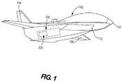
- FIG. 1 illustrates an example of a high speed flight vehicle 102.
- the flight vehicle 102 may be operated piloted or unpiloted, as desired.
- the flight vehicle 102 is just one configuration of a flight vehicle capable of traveling at a speed of at least Mach 3, and other configurations, not shown, may be implemented as desired.
- the flight vehicle 102 may have a different shape, size, aspect ratio, etc., as desired.
- the flight vehicle 102 is merely shown in a particular configuration for purposes of discussion.
- the flight vehicle 102 includes a turbine engine 100, a wing 106, a tail 108, and a nose cap 110.
- the turbine engine 100 is the primary source of propulsion for the flight vehicle 102.
- the embodiments described herein prevent portions of the turbine engine 100 from being heated to temperatures that are near or exceed thermal limits for the materials used in the turbine engine 100.
- the turbine engine 100 illustrated at FIG. 2 includes an inlet air duct 112 having an upstream end 114 for receiving ambient air and a downstream end 116.
- the inlet air duct 112 directs a duct air flow 118 from the upstream end 114 to the downstream end 116.
- the duct air flow 118 includes air that flows across an entire cross-sectional area of the inlet air duct 112.
- the turbine engine 100 includes a fan 120, which is disposed in the inlet air duct 112 and draws air into the inlet air duct 112.
- the turbine engine 100 further includes an engine core 122 for producing propulsion from jet core efflux.
- the engine core 122 is disposed in a center portion of the inlet air duct 112, is operably coupled to the fan 120, and is located downstream of the fan 120.
- the engine core 122 includes a core housing 124, which divides the duct air flow 118 into a core air flow 126, which passes through the core housing 124, and a bypass air flow 128, which passes around the core housing 124.
- An afterburner 130 is disposed in the inlet air duct 112 and downstream of the engine core 122 to selectively provide additional thrust to the flight vehicle 102.
- a portion of the inlet air duct 112 surrounding and downstream of the afterburner 130 includes an afterburner liner 132 for thermal protection of a downstream end of the inlet air duct 112.
- the turbine engine 100 includes cooling to mitigate high temperatures associated with operation of the flight vehicle 102.
- a heat exchanger 140 is used to provide cooling.
- the heat exchanger 140 includes one or more conduits 142 that are in fluidic communication with a heat sink fluid source 144. Heat sink fluid passing through the conduit(s) 142 absorbs heat from the environment surrounding the conduit(s), thereby reducing temperature.
- the heat sink fluid source 144 may be an ancillary source of fluid on the flight vehicle 102, a dedicated thermal management system, a power generation system, or a sub-system that requires heat for operation, or any combination thereof.
- the heat sink fluid may be fuel, water, air, or any other fluid used on or available to the flight vehicle.
- the heat sink fluid may be a supercritical fluid, such as supercritical carbon dioxide, which provides efficient heat transfer while reducing the size and weight of components used in the heat exchanger 140.
- the heat exchanger 140 may be located in different positions within the turbine engine 100, and/or may be provided in different sizes, to provide the desired cooling effect. In FIG. 2 , for example, the heat exchanger 140 is positioned upstream of the fan 120.
- the heat exchanger 140 is configured to absorb heat from an entirety of the duct air flow 118. Accordingly, as shown in FIG. 2 , the heat exchanger 140 extends across an entire cross-section of the inlet air duct 112, thereby reducing temperature across the entire duct air flow 118. Locating the heat exchanger 140 upstream of the fan 120 exposes the heat exchanger to lower temperatures and pressures than those present further downstream, reducing material and other design considerations for the heat exchanger 140. This location of the heat exchanger 140 also provides cooling prior to compression of the air flow, thereby increasing the thermodynamic advantage effected by the heat exchanger 140.
- FIGS. 3-5 illustrates examples in which the heat exchanger 140 cools only a portion of the duct air flow 118.
- the heat exchanger 140 is positioned upstream of the fan, similar to the above example.
- the heat exchanger 140 shown in FIG. 3 extends across only a central portion of the inlet air duct 112.
- the heat exchanger 140 is positions and sized to extend across an area that corresponds to a cross-sectional area of the core housing 124. Consequently, the heat exchanger 140 extracts heat primarily from a portion of the duct air flow 118 that ultimately will pass through the engine core 122 as the core air flow 126.
- the heat exchanger 140 is still located upstream of the fan 120, thereby offering the same heat exchanger design considerations and thermodynamic advantage as the previous example. By covering a smaller area, however, the weight of the heat exchanger 140 is reduced while still cooling the portion of the duct air flow 118 that will see the greatest temperature increase further downstream.
- FIG. 4 illustrates an alternative example in which the heat exchanger 140 is positioned between the fan 120 and the engine core 122.
- the engine core 122 includes a low pressure compressor 123 and a high pressure compressor 125.
- the heat exchanger 140 is disposed within the core housing 124 and upstream of the low pressure compressor 123, and therefore is configured to absorb heat only from the core air flow 126.
- the temperature and density of air at this location is greater than upstream of the fan 120 which permits the heat exchanger 140 to be more compact, thereby reducing the weight of the heat exchanger.
- the thermodynamic advantage of cooling at this location will be reduced, and positioning the heat exchanger 140 between the fan 120 and the low pressure compressor 123 may require the shaft connecting these components to be lengthened, thereby potentially impacting turbomachinery design.
- FIG. 5 illustrates a further example in which the heat exchanger 140 is disposed in the core housing 124, and therefore is configured to absorb heat only from the core air flow 126 portion of the duct air flow 118.
- the heat exchanger 140 is located between the low pressure compressor 123 and the high pressure compressor 125. At this location, the temperature and density of the air is even greater than the heat exchanger location shown in FIG. 4 , thereby allowing the heat exchanger to be even more compact and therefore have less weight.
- the thermodynamic advantage of cooling at this location is further reduced, and again may require the shaft to be lengthened, thereby impacting turbomachinery design.
- FIG. 6 illustrates examples of targeted cooling of specific locations of the turbine engine 100.
- the heat exchanger 140 of FIG. 6 includes one or more spot-cooling heat exchangers 150.
- Each spot-cooling heat exchanger 150 is in fluidic communication with the heat sink fluid source 144, and is configured to cool temperature sensitive areas or components of the turbine engine 100.
- the spot-cooling heat exchanger 150 may be positioned to cool actuators, sensors, controllers, pumps, lubrication systems, or other accessories having more limited operating temperatures than the rest of the turbine engine 100.
- FIG. 6 illustrates targeted cooling at and downstream of the afterburner 130.
- the bypass air flow 128 reaches higher temperatures, thereby reducing the cooling capacity of the bypass air flow 128 to cool structure and components located downstream of the engine core 122.
- the afterburner liner 132 in particular is susceptible to temperatures levels that exceed thermal limits.
- FIG. 6 illustrates a liner cooler 152 configured to cool the afterburner liner 132.
- the liner cooler 152 is positioned upstream of and in longitudinal alignment with the afterburner liner 132.
- the liner cooler 152 is in fluidic communication with the heat sink fluid source 144, thereby absorbing heat from the bypass air flow 128.
- the liner cooler 152 is located adjacent an interior surface of the inlet air duct 112, and therefore has a generally annular shape.
- the flight vehicle 102 includes a nozzle assembly 200 that is configured to expand the operating speed range of the flight vehicle 102.
- the nozzle assembly 200 includes an expansion surface that permits greater support strength and interfacing with sub-systems and/or other components provided on the flight vehicle 102, the ability to adjust the shape and size of a nozzle orifice to maximize propulsive efficiency across a range of operating speeds, and a nozzle cooling system that reduces temperature at the nozzle while also influencing exhaust plume shape and resulting thrust generated by the propulsion system.
- the nozzle assembly 200 is shown coupled to an airframe 202 of the flight vehicle 102.
- the flight vehicle 102 includes an engine 204, and the nozzle assembly 200 is disposed downstream of and in fluid communication with the engine 204.
- the engine 204 may be embodied as the turbine engine 100 shown in Figures 1-6 .
- the nozzle assembly 200 includes a cowl 210 having a cowl neck 212 at an upstream end and a cowl outlet 214 at a downstream end.
- the cowl 210 further includes a cowl internal surface 216 which defines a cowl orifice 218. In the examples disclosed herein, the cowl 210 has an arcuate shape.
- the cowl 210 when viewed along a longitudinal axis 206 of the flight vehicle 102, the cowl 210 extends partially around the longitudinal axis 206.
- the term "arcuate shape" means that the overall profile of the cowl 210 extends around an axis, and is intended to cover cowls that have curvilinear sections, rectilinear sections, or combinations thereof.
- the cowl internal surface 216 includes a cowl surface inlet section 220, a cowl surface transition section 222, and a cowl surface outlet section 224.
- the cowl surface inlet section 220 has a first radius R1 and the cowl surface outlet section 224 has a second radius R2, which is greater than the first radius R1.
- the cowl surface transition section 222 has a radius that gradually increases, at a constant or variable rate, from the first radius R1 to the second radius R2.
- the nozzle assembly 200 further includes a plug 230, which defines a primary thrust surface 232 for the flight vehicle 102.
- the plug 230 is supported from the airframe 202 in cantilevered fashion. That is, the airframe 202 includes a tail section 208 at a rear of the flight vehicle 102, and the plug 230 includes a plug base 231 that is coupled to and depends from the tail section 208 of the airframe 202.
- the plug base 231 extends around a periphery of the primary thrust surface 232 to permit secure attachment of the plug 230 to the airframe 202, while permitting operable coupling of the plug 230 to other systems and components provided on the flight vehicle 102.
- the plug 230 includes a plug wall 234 having a plug wall interior surface 236 and a plug wall exterior surface 238. The plug wall exterior surface 238 defines the primary thrust surface 232.
- the thrust surface 232 is partially axi-symmetric. That is, when viewed from a downstream end of the plug 230, the thrust surface 232 is symmetrical at least partially about a longitudinal axis 233 of the plug 230.
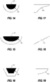
- FIGS. 14 and 15 show examples of the thrust surface 232 having partial ellipsoid shapes.
- FIG. 16 illustrates a thrust surface 232 having a partial prism shape.
- the longitudinal profile of the thrust surface 232 may be provided in different shapes to optimize thrust for a particular speed of the flight vehicle 102.
- the longitudinal profile of the thrust surface 232 is concave, which is advantageous for high speeds, such as hypersonic speeds.
- the longitudinal profile of the thrust surface 232 is convex, which is advantageous for subsonic and transonic speeds.
- FIG. 18 illustrates a longitudinal profiles of the thrust surface 232 that is linear, which is advantageous for speeds between subsonic/transonic and hypersonic speeds.
- the plug 230 is positioned relative to the cowl 210 so that a portion of the primary thrust surface 232 is disposed within the cowl orifice 218.
- the primary thrust surface 232 and the cowl internal surface 216 are spaced to define therebetween a throat 242.
- the cowl 210 and plug 230 are movable relative to each other, thereby to optimize thrust for a given speed of the flight vehicle 102.
- the plug 230 is stationary while the cowl 210 is supported to translate in a direction parallel to the longitudinal axis 206 of the flight vehicle 102.
- the cowl neck 212 is sized to be received in a slot 246 defined by the airframe 202.
- a cowl actuator 248 is operably coupled to the cowl 210 and configured to move the cowl 210 between a rearward position ( FIG. 8 ) and a forward position ( FIG. 9 ).
- Relative movement between the cowl 210 and the plug 230 will change the thrust characteristics produced by the nozzle assembly 200.
- regions of the cowl 210 and plug 230 that are nearest each other will form the throat 242. These regions will change as the cowl 210 and plug 230 move relative to each other.
- the respective contours of the cowl 210 and plug 230 will influence the size, location, angle, and cross-sectional area of the throat 242, thereby impacting thrust characteristics.
- the cross-sectional area of the throat 242 is a primary control for the propulsion system. Throat location and angle also affect flow for the rest of the nozzle assembly 200, thereby affecting thrust efficiency.
- the contours of the cowl 210 and plug 230 influence the location of the throat 242, which affects the amount of internal expansion of the nozzle assembly 200.
- Control over the amount of internal expansion is a design factor used to produce high nozzle efficiency over a broad range of Mach numbers.
- low internal expansion is advantageous subsonic and transonic flight speeds, while high internal expansion is advantageous for supersonic and hypersonic speeds.
- the ability to produce relative movement between the cowl 210 and the plug 230 allows the nozzle assembly 200 to optimize throat size, location, angle, and cross-sectional area for a particular flight speed, thereby expanding the speed range of the flight vehicle 102.
- FIGS. 7-9 show a stationary plug 230 and a movable cowl 210 that can translate in a direction parallel to the longitudinal axis 206
- the cowl 210 is stationary and the plug 230 is movable, as shown in FIG. 10 .
- both the cowl 210 and plug 230 may be movable.
- the cowl 210 and/or plug 230 may execute motions other than translation in a direction parallel to the longitudinal axis 206 to achieve relative movement of the cowl 210 and plug 230.
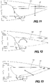
- FIG. 11 illustrates a plug 230 that is movable in a direction that is perpendicular to the longitudinal axis 206, while the cowl 210 is stationary.
- FIG. 12 illustrates a plug 230 that is rotatable relative to a stationary cowl 210.
- FIG. 13 illustrates a plug 230 that translates in a direction that is at an angle relative to the longitudinal axis 206.
- the nozzle assembly 200 includes a nozzle cooling system 250 that primarily reduces temperature at the nozzle assembly 200. Additionally, some examples of the nozzle cooling system 250 also influence a shape of the exhaust plume, thereby altering characteristics of the thrust generated by the nozzle assembly 200.
- the nozzle cooling system 250 includes a coolant source 252 that is thermally coupled to the primary thrust surface 232.
- the coolant source 252 may be ambient or bypass air, fluid from a thermal management system provided on the flight vehicle 102, or fluid from any other sub-system provided on the flight vehicle.
- the coolant may be fuel, water, air, or any other fluid used on or available to the flight vehicle.
- the coolant may be a supercritical fluid, such as supercritical carbon dioxide.
- coolant from the coolant source 252 is contained within the plug 230.
- the plug wall 234 is impervious, and the coolant source 252 is in fluidic communication with the plug wall interior surface 236.
- As coolant flows to the plug 230 it cools the plug wall interior surface 236, which in turn cools the plug wall exterior surface 238 via conduction. Heated coolant can be recycled by to the coolant source 252 or other destination, or discharged from the flight vehicle 102.
- coolant from the coolant source 252 passes through the plug wall 234 to directly cool the plug wall exterior surface 238.
- the plug wall 234 includes perforations 254 extending from the plug wall interior surface 236 to the plug wall exterior surface 238.
- the perforations 254 may be provided in a variety of profile shapes and distribution patterns, which will effect the amount and location of cooling and the coolant flow rate. For example, if plug materials are used that are rated for sufficiently high temperatures, and/or engine exhaust flows are sufficiently cool, fewer perforations, smaller sized perforations, and/or a lower coolant flow rate may be used, reducing a weight of the nozzle cooling system 250.
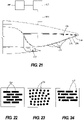
- FIG. 22 illustrates perforations 254 having rectilinear profiles
- FIG. 23 illustrates perforations 254 having curvilinear profiles
- the perforations 254 have both rectilinear and curvilinear profiles.
- perforations 254 having curvilinear profiles may better align coolant flow to the plug wall exterior surface 238.
- the coolant regulator 253 selectively controls flow of coolant from the coolant source 252 to the plug wall interior surface 236. From the plug wall interior surface 236, coolant flows through the perforations 254 to form a film on the plug wall exterior surface 238.
- the coolant absorbs heat from both the plug wall exterior surface 238 and the exhaust gas, and may be discharged from the tail of the flight vehicle 102.
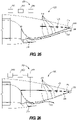
- FIGS. 25 and 26 illustrate how the flow rate of the coolant can be adjusted to change thrust characteristics.
- the coolant flow rate is low, which results in exhaust gas 258 remaining in contact with the primary thrust surface 232 for a longer period and prevents overexpansion of exhaust gas 258, which is advantageous during lower operating speeds of the flight vehicle 102.
- FIG. 26 illustrates a coolant rate that is high, which is advantageous during higher operating speeds of the flight vehicle 102. More specifically, during high speed operation, the coolant primarily provides cooling to the nozzle assembly 200, as overexpansion of the exhaust gas 258 is of less concern.
- a controller 260 is provided to control operation of the nozzle assembly 200.
- the controller 260 is operably coupled to the coolant regulator 253 to control the coolant flow rate as desired.
- the specific hardware implementation of the controller 260 is subject to design choices, one particular example includes one or more processors coupled with a current driver.
- the one or more processors may include any electronic circuits and/or optical circuits that are able to perform the functions described herein.
- the processor(s) may perform any functionality described herein for controller 260.
- the processor(s) may include one or more Central Processing Units (CPU), microprocessors, Digital Signal Processors (DSPs), Application-specific Integrated Circuits (ASICs), Programmable Logic Devices (PLD), control circuitry, etc.
- CPU Central Processing Unit
- DSP Digital Signal Processor
- ASIC Application-specific Integrated Circuit
- PLD Programmable Logic Device
- Some examples of processors include INTEL ® CORE TM processors, Advanced Reduced Instruction Set Computing (RISC) Machines (ARM ® ) processors, etc.
- any of the various elements shown in the figures or described herein may be implemented as hardware, software, firmware, or some combination of these.
- an element may be implemented as dedicated hardware.
- Dedicated hardware elements may be referred to as "processors", “controllers”, or some similar terminology.
- processors When provided by a processor, the functions may be provided by a single dedicated processor, by a single shared processor, or by a plurality of individual processors, some of which may be shared.
- processor or “controller” should not be construed to refer exclusively to hardware capable of executing software, and may implicitly include, without limitation, digital signal processor (DSP) hardware, a network processor, application specific integrated circuit (ASIC) or other circuitry, field programmable gate array (FPGA), read only memory (ROM) for storing software, random access memory (RAM), non-volatile storage, logic, or some other physical hardware component or module.
- DSP digital signal processor
- ASIC application specific integrated circuit
- FPGA field programmable gate array
- ROM read only memory
- RAM random access memory
- non-volatile storage logic, or some other physical hardware component or module.
- an element may be implemented as instructions executable by a processor or a computer to perform the functions of the element.
- Some examples of instructions are software, program code, and firmware.
- the instructions are operational when executed by the processor to direct the processor to perform the functions of the element.
- the instructions may be stored on storage devices that are readable by the processor. Some examples of the storage devices are digital or solid-state memories, magnetic storage media such as a magnetic disks and magnetic tapes, hard drives, or optically readable digital data storage media.
- a turbine engine for a high speed flight vehicle comprises an inlet air duct having an upstream end for receiving ambient air and a downstream end, the inlet air duct directing a duct air flow from the upstream end to the downstream end, a fan disposed in the inlet air duct, an engine core disposed in the inlet air duct and operably coupled to the fan, the engine core being disposed downstream of the fan and including a core housing, through which passes a core air flow portion of the duct air flow, and an afterburner disposed in the inlet air duct and downstream of the engine core.
- a heat exchanger is disposed in the inlet air duct.
- the heat exchanger is positioned upstream of the fan, and the heat exchanger is configured to absorb heat from an entirety of the duct air flow.
- the heat exchanger is positioned upstream of the fan, and the heat exchanger is configured to absorb heat from the core air flow portion of the duct air flow.
- the heat exchanger is positioned between the fan and the engine core, and the heat exchanger is configured to absorb heat from the core air flow portion of the duct air flow.
- the engine core further comprises a low pressure compressor disposed in the core housing and a high pressure compressor disposed in the core housing and located downstream of the low pressure compressor, the heat exchanger is positioned between the low pressure compressor and the high pressure compressor, and the heat exchanger is configured to absorb heat from the core air flow portion of the duct air flow.
- the heat exchanger further comprises at least one spot-cooling heat exchanger disposed within the core housing.
- the inlet air duct includes an afterburner liner surrounding the afterburner, and the heat exchanger further comprises a liner cooler positioned upstream of and in longitudinal alignment with the afterburner liner.
- a nozzle assembly for a flight vehicle having an engine, the nozzle assembly comprising a cowl in fluidic communication with the engine, the cowl including a cowl internal surface defining a cowl orifice, a plug defining a primary thrust surface, wherein the plug is supported relative to the cowl so that a portion of the primary thrust surface is disposed within the cowl orifice, wherein the primary thrust surface of the plug and the cowl internal surface are spaced to define a throat, and an actuator coupled to at least one of the cowl or the plug, the actuator configured to generate relative movement between the cowl and the plug, thereby to modify the throat.
- the nozzle assembly further comprises a coolant system having a source of coolant thermally coupled to the primary thrust surface of the plug.
- the primary thrust surface is formed by a plug wall having a plug wall interior surface and a plug wall exterior surface, wherein the plug wall exterior surface forms the primary thrust surface of the plug.
- the plug wall is impervious, and the coolant system directs coolant onto the plug wall interior surface.
- the plug wall defines perforations extending from the plug wall interior surface to the plug wall exterior surface, and in which the coolant system directs coolant to the plug wall interior surface, through the perforations, and onto the plug wall exterior surface.
- the coolant system comprises a coolant regulator configured to adjust a coolant flow rate at which coolant is supplied to the plug from the coolant source.
- the perforations comprise rectilinear perforation profiles.
- the perforations comprise curvilinear perforation profiles.
- the perforations comprise both rectilinear perforation profiles and curvilinear perforation profiles.
- the coolant source comprises bypass air.
- the plug is stationary and the cowl is movable relative to the plug.
- the cowl is stationary and the plug is movable relative to the cowl.
- both the cowl and the plug are movable.
- the relative movement between the cowl and the plug is translation.
- the translation is in a direction that is parallel to a longitudinal axis of an airframe of the flight vehicle.
- the translation is in a direction that is perpendicular to a longitudinal axis of an airframe of the flight vehicle.
- the translation is at an angle relative to a longitudinal axis of an airframe of the flight vehicle.
- the relative movement between the cowl and the plug is angular rotation.
- the primary thrust surface of the plug comprises a partial-axisymmetric shape.
- the plug further comprises a plug base coupled to an airframe of the flight vehicle.
- the partial-axisymmetric shape is a partial ellipsoid shape.
- the primary thrust surface of the plug comprises a partial prism shape.
- a flight vehicle comprises an airframe, an inlet duct coupled to the airframe, an engine disposed in the inlet duct, and a nozzle assembly disposed downstream of the engine.
- the nozzle assembly comprises a cowl in fluidic communication with the engine, the cowl including a cowl internal surface defining a cowl orifice, and a plug defining a primary thrust surface, wherein the plug is supported by the airframe relative to the cowl so that a portion of the primary thrust surface is disposed within the cowl orifice, wherein the primary thrust surface of the plug and the cowl internal surface are spaced to define a throat.
- An actuator is coupled to at least one of the cowl or the plug, and is configured to generate relative movement between the cowl and the plug, thereby to modify the throat.
- a nozzle assembly for a flight vehicle having an engine and an airframe.
- the nozzle assembly comprises a cowl in fluidic communication with the engine, the cowl including a cowl internal surface defining a cowl orifice.
- the nozzle assembly further comprises a plug defining a primary thrust surface, wherein the plug is supported by the airframe relative to the cowl so that a portion of the primary thrust surface is disposed within the cowl orifice, wherein the primary thrust surface of the plug and the cowl internal surface are spaced to define a throat, the primary thrust surface comprising a partial axi-symmetrical shape.
- An actuator is coupled to at least one of the cowl or the plug, the actuator configured to generate relative movement between the cowl and the plug, thereby to modify the throat, and a coolant source is thermally coupled to the primary thrust surface of the plug.
- a method of providing thrust to a flight vehicle that has an engine and an airframe comprises providing a nozzle assembly.
- the nozzle assembly comprises a cowl in fluidic communication with the engine, the cowl including a cowl internal surface defining a cowl orifice, and a plug defining a primary thrust surface, wherein the plug is supported by the airframe relative to the cowl so that a portion of the primary thrust surface is disposed within the cowl orifice, wherein the primary thrust surface of the plug and the cowl internal surface are spaced to define a throat.
- the method further comprises generating relative movement between the cowl and the plug, thereby to modify the throat.
- the method further comprises cooling the primary thrust surface of the plug.
- cooling the primary thrust surface of the plug comprises providing coolant to a plug wall exterior surface.
- the method further comprises controlling a flow rate of the coolant to the plug wall exterior surface so that the coolant is injected into exhaust gas flow from the nozzle assembly.
Landscapes
- Engineering & Computer Science (AREA)
- Chemical & Material Sciences (AREA)
- Combustion & Propulsion (AREA)
- Mechanical Engineering (AREA)
- General Engineering & Computer Science (AREA)
- Aviation & Aerospace Engineering (AREA)
- Health & Medical Sciences (AREA)
- General Health & Medical Sciences (AREA)
- Pulmonology (AREA)
- Structures Of Non-Positive Displacement Pumps (AREA)
- Turbine Rotor Nozzle Sealing (AREA)
- General Details Of Gearings (AREA)
Abstract
Description
- The present disclosure generally relates to high speed flight vehicles and, more specifically, to systems and methods for expanding operating ranges of high speed flight vehicles.
- Operating conditions at high flight speeds present various challenges to flight vehicle design. For example, a gas turbine engine of a flight vehicle traveling through atmosphere at speeds greater than Mach 3, and more particularly at hypersonic speeds greater than Mach 5, may experience localized temperatures that reach or exceed a material temperature limit. In conventional flight vehicle design, the engine is throttled back as the temperature nears the material temperature limit, thereby to avoid exceeding the material temperature limit. When excessive throttling back is needed due to high temperatures, the engine no longer accelerates the flight vehicle, thereby limiting a top operating speed of the flight vehicle. Additionally, nozzle design may impose limits on the operating range of the flight vehicle. For example, a nozzle configured for speeds greater than Mach 3 may induce over-expansion drag at lower speeds, or may otherwise fail to provide propulsive efficiency across a range of operating speeds of the flight vehicle.
- In accordance with one aspect of the present disclosure, a turbine engine for a high speed flight vehicle comprises an inlet air duct having an upstream end for receiving ambient air and a downstream end, the inlet air duct directing a duct air flow from the upstream end to the downstream end, and a fan disposed in the inlet air duct. An engine core is disposed in the inlet air duct and operably coupled to the fan, the engine core being disposed downstream of the fan and including a core housing, through which passes a core air flow portion of the duct air flow. An afterburner is disposed in the inlet air duct and downstream of the engine core, and a heat exchanger disposed in the inlet air duct. In accordance with another aspect of the present disclosure, a nozzle assembly is provided for a flight vehicle having an engine. The nozzle assembly comprises a cowl in fluidic communication with the engine, the cowl including a cowl internal surface defining a cowl orifice, and a plug defining a primary thrust surface, wherein the plug is supported relative to the cowl so that a portion of the primary thrust surface is disposed within the cowl orifice, wherein the primary thrust surface of the plug and the cowl internal surface are spaced to define a throat. An actuator is coupled to at least one of the cowl or the plug, and is configured to generate relative movement between the cowl and the plug, thereby to modify the throat.
- In accordance with a further aspect of the present disclosure, a method is provided of controlling thrust to a flight vehicle having an engine and an airframe. The method comprises providing a nozzle assembly comprising a cowl in fluidic communication with the engine, the cowl including a cowl internal surface defining a cowl orifice, and a plug defining a primary thrust surface, wherein the plug is supported by the airframe relative to the cowl so that a portion of the primary thrust surface is disposed within the cowl orifice, wherein the primary thrust surface of the plug and the cowl internal surface are spaced to define a throat. The method further comprises generating relative movement between the cowl and the plug, thereby to modify the throat.
- The features, functions, and advantages that have been discussed can be achieved independently in various examples or may be combined in yet other examples further details of which can be seen with reference to the following description and drawings.
- The novel features believed characteristic of the illustrative examples are set forth in the appended claims. The illustrative examples, however, as well as a preferred mode of use, further objectives and advantages thereof, will best be understood by reference to the following detailed description of illustrative examples of the present disclosure when read in conjunction with the accompanying drawings, wherein:
-
FIG. 1 is a perspective view of a high speed flight vehicle having an integrated cooling and power generation system according to the present disclosure. -
FIG. 2 is a schematic illustration of a turbine engine with air cooling across an entire air flow. -
FIG. 3 is a schematic illustration of a turbine engine with air cooling across a core air flow. -
FIG. 4 is a schematic illustration of an alternative example of a turbine engine with air cooling across a core air flow. -
FIG. 5 is a schematic illustration of a further example of a turbine engine with air cooling across a core air flow. -
FIG. 6 is a schematic illustration of a turbine engine with spot cooling in an engine core and afterburner liner. -
FIG. 7 is a perspective view of a tail portion of the high speed flight vehicle ofFIG. 1 . -
FIG. 8 is a side elevation view, in partial cross section, of the tail portion of the high speed flight vehicle ofFIG. 7 , with a cowl and a primary thrust surface in first positions relative to each other. -
FIG. 9 is a side elevation view, in partial cross-section, of the tail portion of the high speed flight vehicle ofFIG. 7 , with the cowl and primary thrust surface in second positions relative to each other. -
FIG. 10 is a side elevation view of the tail portion of the high speed flight vehicle ofFIG. 7 , showing a primary thrust surface that translates parallel to a longitudinal axis of the flight vehicle. -
FIG. 11 is a side elevation view of the tail portion of the high speed flight vehicle ofFIG. 7 , showing a primary thrust surface that translates in a direction perpendicular to a longitudinal axis of the flight vehicle. -
FIG. 12 is a side elevation view of the tail portion of the high speed flight vehicle ofFIG. 7 , showing a primary thrust surface that rotates relative to an airframe of the flight vehicle. -
FIG. 13 is a side elevation view of the tail portion of the high speed flight vehicle ofFIG. 7 , showing a primary thrust surface that translates in a direction that is at an angle relative to the longitudinal axis of the flight vehicle. -
FIG. 14 is a schematic end view diagram of a first example of a shape of a thrust surface. -
FIG. 15 is a schematic end view diagram of a second example of a shape of a thrust surface. -
FIG. 16 is a schematic end view diagram of a third example of a shape of a thrust surface. -
FIG. 17 is schematic side view diagram of a first example of a thrust surface longitudinal profile. -
FIG. 18 is schematic side view diagram of a second example of a thrust surface longitudinal profile. -
FIG. 19 is schematic side view diagram of a third example of a thrust surface longitudinal profile. -
FIG. 20 is a side elevation view, in partial cross-section, of the tail portion of the high speed flight vehicle ofFIG. 7 , showing a first example of a nozzle cooling system. -
FIG. 21 is a side elevation view, in partial cross-section, of the tail portion of the high speed flight vehicle ofFIG. 7 , showing a second example of a nozzle cooling system. -
FIGS. 22-24 are schematic plan view diagrams showing examples of perforation profiles formed in a plug wall of the nozzle assembly. -
FIG. 25 is a side elevation view, in partial cross-section, of the tail portion of the high speed flight vehicle ofFIG. 7 , showing a low flow rate of coolant to the nozzle assembly. -
FIG. 26 is a side elevation view, in partial cross-section, of the tail portion of the high speed flight vehicle ofFIG. 7 , showing a high flow rate of coolant to the nozzle assembly. - The figures and the following description illustrate specific examples of the claimed subject matter. It will thus be appreciated that those skilled in the art will be able to devise various arrangements that, although not explicitly described or shown herein, embody the principles of the examples and are included within the scope of the examples. Furthermore, any examples described herein are intended to aid in understanding the principles of construction, operation, or other features of the disclosed subject matter, and are to be construed as being without limitation to such specifically recited examples and conditions. As a result, the inventive concept(s) is not limited to the specific examples described below, but by the claims and their equivalents.
- Examples of a turbine engine for a high speed flight vehicle described herein provide cooling to permit operation of the flight vehicle at higher speeds. A heat exchanger is used to cool air passing through an inlet duct, a core housing, specific components of an engine core, and/or a liner of the duct adjacent an afterburner, thereby preventing the temperature of the components from reaching thermal limits. As a result, the turbine engine may continue operation without throttle reduction, thereby increasing the upper end of the range at which the flight vehicle travels.
-
FIG. 1 illustrates an example of a highspeed flight vehicle 102. Theflight vehicle 102 may be operated piloted or unpiloted, as desired. Theflight vehicle 102 is just one configuration of a flight vehicle capable of traveling at a speed of at least Mach 3, and other configurations, not shown, may be implemented as desired. For example, theflight vehicle 102 may have a different shape, size, aspect ratio, etc., as desired. Thus, theflight vehicle 102 is merely shown in a particular configuration for purposes of discussion. - In this example, the
flight vehicle 102 includes aturbine engine 100, awing 106, atail 108, and anose cap 110. Theturbine engine 100 is the primary source of propulsion for theflight vehicle 102. During operation of theflight vehicle 102 above Mach 3, or in hypersonic flight (e.g., theflight vehicle 102 moves at hypersonic speeds of Mach 5 and above), the embodiments described herein prevent portions of theturbine engine 100 from being heated to temperatures that are near or exceed thermal limits for the materials used in theturbine engine 100. - In the examples illustrated at
FIGS. 2-6 , the airflow and/or specific components or areas of theturbine engine 100 are cooled to reduced temperatures below the thermal limit, thereby permitting theflight vehicle 102 to operate at higher speeds. Theturbine engine 100 illustrated atFIG. 2 , for example, includes aninlet air duct 112 having anupstream end 114 for receiving ambient air and adownstream end 116. Theinlet air duct 112 directs aduct air flow 118 from theupstream end 114 to thedownstream end 116. As used herein, theduct air flow 118 includes air that flows across an entire cross-sectional area of theinlet air duct 112. Theturbine engine 100 includes afan 120, which is disposed in theinlet air duct 112 and draws air into theinlet air duct 112. - The
turbine engine 100 further includes anengine core 122 for producing propulsion from jet core efflux. Theengine core 122 is disposed in a center portion of theinlet air duct 112, is operably coupled to thefan 120, and is located downstream of thefan 120. Theengine core 122 includes acore housing 124, which divides theduct air flow 118 into acore air flow 126, which passes through thecore housing 124, and abypass air flow 128, which passes around thecore housing 124. Anafterburner 130 is disposed in theinlet air duct 112 and downstream of theengine core 122 to selectively provide additional thrust to theflight vehicle 102. A portion of theinlet air duct 112 surrounding and downstream of theafterburner 130 includes anafterburner liner 132 for thermal protection of a downstream end of theinlet air duct 112. - The
turbine engine 100 includes cooling to mitigate high temperatures associated with operation of theflight vehicle 102. In the example illustrated atFIGS. 2-6 , aheat exchanger 140 is used to provide cooling. Theheat exchanger 140 includes one ormore conduits 142 that are in fluidic communication with a heatsink fluid source 144. Heat sink fluid passing through the conduit(s) 142 absorbs heat from the environment surrounding the conduit(s), thereby reducing temperature. The heatsink fluid source 144 may be an ancillary source of fluid on theflight vehicle 102, a dedicated thermal management system, a power generation system, or a sub-system that requires heat for operation, or any combination thereof. For example, the heat sink fluid may be fuel, water, air, or any other fluid used on or available to the flight vehicle. In some examples, the heat sink fluid may be a supercritical fluid, such as supercritical carbon dioxide, which provides efficient heat transfer while reducing the size and weight of components used in theheat exchanger 140. - The
heat exchanger 140 may be located in different positions within theturbine engine 100, and/or may be provided in different sizes, to provide the desired cooling effect. InFIG. 2 , for example, theheat exchanger 140 is positioned upstream of thefan 120. - Additionally, the
heat exchanger 140 is configured to absorb heat from an entirety of theduct air flow 118. Accordingly, as shown inFIG. 2 , theheat exchanger 140 extends across an entire cross-section of theinlet air duct 112, thereby reducing temperature across the entireduct air flow 118. Locating theheat exchanger 140 upstream of thefan 120 exposes the heat exchanger to lower temperatures and pressures than those present further downstream, reducing material and other design considerations for theheat exchanger 140. This location of theheat exchanger 140 also provides cooling prior to compression of the air flow, thereby increasing the thermodynamic advantage effected by theheat exchanger 140. -
FIGS. 3-5 illustrates examples in which theheat exchanger 140 cools only a portion of theduct air flow 118. In the example ofFIG. 3 , theheat exchanger 140 is positioned upstream of the fan, similar to the above example. Unlike in the example illustrated inFIG. 2 , however, theheat exchanger 140 shown inFIG. 3 extends across only a central portion of theinlet air duct 112. Specifically, theheat exchanger 140 is positions and sized to extend across an area that corresponds to a cross-sectional area of thecore housing 124. Consequently, theheat exchanger 140 extracts heat primarily from a portion of theduct air flow 118 that ultimately will pass through theengine core 122 as thecore air flow 126. In this example, theheat exchanger 140 is still located upstream of thefan 120, thereby offering the same heat exchanger design considerations and thermodynamic advantage as the previous example. By covering a smaller area, however, the weight of theheat exchanger 140 is reduced while still cooling the portion of theduct air flow 118 that will see the greatest temperature increase further downstream. -
FIG. 4 illustrates an alternative example in which theheat exchanger 140 is positioned between thefan 120 and theengine core 122. In this example, theengine core 122 includes alow pressure compressor 123 and ahigh pressure compressor 125. Theheat exchanger 140 is disposed within thecore housing 124 and upstream of thelow pressure compressor 123, and therefore is configured to absorb heat only from thecore air flow 126. The temperature and density of air at this location is greater than upstream of thefan 120 which permits theheat exchanger 140 to be more compact, thereby reducing the weight of the heat exchanger. The thermodynamic advantage of cooling at this location, however, will be reduced, and positioning theheat exchanger 140 between thefan 120 and thelow pressure compressor 123 may require the shaft connecting these components to be lengthened, thereby potentially impacting turbomachinery design. -
FIG. 5 illustrates a further example in which theheat exchanger 140 is disposed in thecore housing 124, and therefore is configured to absorb heat only from thecore air flow 126 portion of theduct air flow 118. In this example, theheat exchanger 140 is located between thelow pressure compressor 123 and thehigh pressure compressor 125. At this location, the temperature and density of the air is even greater than the heat exchanger location shown inFIG. 4 , thereby allowing the heat exchanger to be even more compact and therefore have less weight. The thermodynamic advantage of cooling at this location, however, is further reduced, and again may require the shaft to be lengthened, thereby impacting turbomachinery design. -
FIG. 6 illustrates examples of targeted cooling of specific locations of theturbine engine 100. Theheat exchanger 140 ofFIG. 6 includes one or more spot-coolingheat exchangers 150. Each spot-coolingheat exchanger 150 is in fluidic communication with the heatsink fluid source 144, and is configured to cool temperature sensitive areas or components of theturbine engine 100. For example, the spot-coolingheat exchanger 150 may be positioned to cool actuators, sensors, controllers, pumps, lubrication systems, or other accessories having more limited operating temperatures than the rest of theturbine engine 100. - Additionally,
FIG. 6 illustrates targeted cooling at and downstream of theafterburner 130. When traveling at higher speeds, such as aboveMach 3, thebypass air flow 128 reaches higher temperatures, thereby reducing the cooling capacity of thebypass air flow 128 to cool structure and components located downstream of theengine core 122. Theafterburner liner 132 in particular is susceptible to temperatures levels that exceed thermal limits.FIG. 6 illustrates a liner cooler 152 configured to cool theafterburner liner 132. Theliner cooler 152 is positioned upstream of and in longitudinal alignment with theafterburner liner 132. Theliner cooler 152 is in fluidic communication with the heatsink fluid source 144, thereby absorbing heat from thebypass air flow 128. In the illustrated embodiment, theliner cooler 152 is located adjacent an interior surface of theinlet air duct 112, and therefore has a generally annular shape. - In additional examples illustrated in
FIGS. 7-26 , theflight vehicle 102 includes anozzle assembly 200 that is configured to expand the operating speed range of theflight vehicle 102. Thenozzle assembly 200 includes an expansion surface that permits greater support strength and interfacing with sub-systems and/or other components provided on theflight vehicle 102, the ability to adjust the shape and size of a nozzle orifice to maximize propulsive efficiency across a range of operating speeds, and a nozzle cooling system that reduces temperature at the nozzle while also influencing exhaust plume shape and resulting thrust generated by the propulsion system. - As best shown in
FIGS. 7-9 , thenozzle assembly 200 is shown coupled to anairframe 202 of theflight vehicle 102. Theflight vehicle 102 includes anengine 204, and thenozzle assembly 200 is disposed downstream of and in fluid communication with theengine 204. Theengine 204 may be embodied as theturbine engine 100 shown inFigures 1-6 . Thenozzle assembly 200 includes acowl 210 having acowl neck 212 at an upstream end and acowl outlet 214 at a downstream end. Thecowl 210 further includes a cowlinternal surface 216 which defines acowl orifice 218. In the examples disclosed herein, thecowl 210 has an arcuate shape. That is, when viewed along alongitudinal axis 206 of theflight vehicle 102, thecowl 210 extends partially around thelongitudinal axis 206. As used herein, the term "arcuate shape" means that the overall profile of thecowl 210 extends around an axis, and is intended to cover cowls that have curvilinear sections, rectilinear sections, or combinations thereof. The cowlinternal surface 216 includes a cowlsurface inlet section 220, a cowlsurface transition section 222, and a cowlsurface outlet section 224. The cowlsurface inlet section 220 has a first radius R1 and the cowlsurface outlet section 224 has a second radius R2, which is greater than the first radius R1. The cowlsurface transition section 222 has a radius that gradually increases, at a constant or variable rate, from the first radius R1 to the second radius R2. - With continued reference to
FIGS. 7-9 , thenozzle assembly 200 further includes aplug 230, which defines aprimary thrust surface 232 for theflight vehicle 102. Theplug 230 is supported from theairframe 202 in cantilevered fashion. That is, theairframe 202 includes atail section 208 at a rear of theflight vehicle 102, and theplug 230 includes aplug base 231 that is coupled to and depends from thetail section 208 of theairframe 202. In the illustrated examples, theplug base 231 extends around a periphery of theprimary thrust surface 232 to permit secure attachment of theplug 230 to theairframe 202, while permitting operable coupling of theplug 230 to other systems and components provided on theflight vehicle 102. Theplug 230 includes aplug wall 234 having a plug wallinterior surface 236 and a plugwall exterior surface 238. The plugwall exterior surface 238 defines theprimary thrust surface 232. - As shown in
FIGS. 7-9 and14-15 , thethrust surface 232 is partially axi-symmetric. That is, when viewed from a downstream end of theplug 230, thethrust surface 232 is symmetrical at least partially about alongitudinal axis 233 of theplug 230.FIGS. 14 and 15 show examples of thethrust surface 232 having partial ellipsoid shapes.FIG. 16 illustrates athrust surface 232 having a partial prism shape. Additionally, the longitudinal profile of thethrust surface 232 may be provided in different shapes to optimize thrust for a particular speed of theflight vehicle 102. InFIG. 17 , the longitudinal profile of thethrust surface 232 is concave, which is advantageous for high speeds, such as hypersonic speeds. InFIG. 19 , the longitudinal profile of thethrust surface 232 is convex, which is advantageous for subsonic and transonic speeds.FIG. 18 illustrates a longitudinal profiles of thethrust surface 232 that is linear, which is advantageous for speeds between subsonic/transonic and hypersonic speeds. - The
plug 230 is positioned relative to thecowl 210 so that a portion of theprimary thrust surface 232 is disposed within thecowl orifice 218. Theprimary thrust surface 232 and the cowlinternal surface 216 are spaced to define therebetween athroat 242. The area of thethroat 242, as well as the shapes of theprimary thrust surface 232 and cowlinternal surface 216, influence the direction and magnitude of thrust produced by thenozzle assembly 200. - The
cowl 210 and plug 230 are movable relative to each other, thereby to optimize thrust for a given speed of theflight vehicle 102. In the embodiment shown inFIGS. 7-9 , theplug 230 is stationary while thecowl 210 is supported to translate in a direction parallel to thelongitudinal axis 206 of theflight vehicle 102. More specifically, thecowl neck 212 is sized to be received in aslot 246 defined by theairframe 202. Acowl actuator 248 is operably coupled to thecowl 210 and configured to move thecowl 210 between a rearward position (FIG. 8 ) and a forward position (FIG. 9 ). - Relative movement between the
cowl 210 and theplug 230 will change the thrust characteristics produced by thenozzle assembly 200. For example, regions of thecowl 210 and plug 230 that are nearest each other will form thethroat 242. These regions will change as thecowl 210 and plug 230 move relative to each other. Accordingly, the respective contours of thecowl 210 and plug 230 will influence the size, location, angle, and cross-sectional area of thethroat 242, thereby impacting thrust characteristics. For example, the cross-sectional area of thethroat 242 is a primary control for the propulsion system. Throat location and angle also affect flow for the rest of thenozzle assembly 200, thereby affecting thrust efficiency. Still further, in some examples the contours of thecowl 210 and plug 230 influence the location of thethroat 242, which affects the amount of internal expansion of thenozzle assembly 200. Control over the amount of internal expansion is a design factor used to produce high nozzle efficiency over a broad range of Mach numbers. For example, low internal expansion is advantageous subsonic and transonic flight speeds, while high internal expansion is advantageous for supersonic and hypersonic speeds. Accordingly, the ability to produce relative movement between thecowl 210 and theplug 230 allows thenozzle assembly 200 to optimize throat size, location, angle, and cross-sectional area for a particular flight speed, thereby expanding the speed range of theflight vehicle 102. - While the examples of
FIGS. 7-9 show astationary plug 230 and amovable cowl 210 that can translate in a direction parallel to thelongitudinal axis 206, in other examples thecowl 210 is stationary and theplug 230 is movable, as shown inFIG. 10 . Still further, both thecowl 210 and plug 230 may be movable. Additionally or alternatively, thecowl 210 and/or plug 230 may execute motions other than translation in a direction parallel to thelongitudinal axis 206 to achieve relative movement of thecowl 210 and plug 230.FIG. 11 illustrates aplug 230 that is movable in a direction that is perpendicular to thelongitudinal axis 206, while thecowl 210 is stationary.FIG. 12 illustrates aplug 230 that is rotatable relative to astationary cowl 210.FIG. 13 illustrates aplug 230 that translates in a direction that is at an angle relative to thelongitudinal axis 206. - In some examples, the
nozzle assembly 200 includes anozzle cooling system 250 that primarily reduces temperature at thenozzle assembly 200. Additionally, some examples of thenozzle cooling system 250 also influence a shape of the exhaust plume, thereby altering characteristics of the thrust generated by thenozzle assembly 200. - More specifically, the
nozzle cooling system 250 includes acoolant source 252 that is thermally coupled to theprimary thrust surface 232. Thecoolant source 252 may be ambient or bypass air, fluid from a thermal management system provided on theflight vehicle 102, or fluid from any other sub-system provided on the flight vehicle. For example, the coolant may be fuel, water, air, or any other fluid used on or available to the flight vehicle. In some examples, the coolant may be a supercritical fluid, such as supercritical carbon dioxide. - In the example shown in
FIG. 20 , coolant from thecoolant source 252 is contained within theplug 230. In this example, theplug wall 234 is impervious, and thecoolant source 252 is in fluidic communication with the plug wallinterior surface 236. Acoolant regulator 253, such as a pump or valve, controls flow of coolant from thecoolant source 252 to theplug 230. As coolant flows to theplug 230, it cools the plug wallinterior surface 236, which in turn cools the plugwall exterior surface 238 via conduction. Heated coolant can be recycled by to thecoolant source 252 or other destination, or discharged from theflight vehicle 102. - In the examples illustrated in
FIGS. 21-24 , coolant from thecoolant source 252 passes through theplug wall 234 to directly cool the plugwall exterior surface 238. In these examples, theplug wall 234 includesperforations 254 extending from the plug wallinterior surface 236 to the plugwall exterior surface 238. Theperforations 254 may be provided in a variety of profile shapes and distribution patterns, which will effect the amount and location of cooling and the coolant flow rate. For example, if plug materials are used that are rated for sufficiently high temperatures, and/or engine exhaust flows are sufficiently cool, fewer perforations, smaller sized perforations, and/or a lower coolant flow rate may be used, reducing a weight of thenozzle cooling system 250.FIG. 22 illustratesperforations 254 having rectilinear profiles, whileFIG. 23 illustratesperforations 254 having curvilinear profiles. InFIG. 24 , theperforations 254 have both rectilinear and curvilinear profiles. Without wishing to be bound by theory,perforations 254 having curvilinear profiles may better align coolant flow to the plugwall exterior surface 238. Thecoolant regulator 253 selectively controls flow of coolant from thecoolant source 252 to the plug wallinterior surface 236. From the plug wallinterior surface 236, coolant flows through theperforations 254 to form a film on the plugwall exterior surface 238. The coolant absorbs heat from both the plugwall exterior surface 238 and the exhaust gas, and may be discharged from the tail of theflight vehicle 102. -
FIGS. 25 and 26 illustrate how the flow rate of the coolant can be adjusted to change thrust characteristics. InFIG. 25 , the coolant flow rate is low, which results inexhaust gas 258 remaining in contact with theprimary thrust surface 232 for a longer period and prevents overexpansion ofexhaust gas 258, which is advantageous during lower operating speeds of theflight vehicle 102.FIG. 26 illustrates a coolant rate that is high, which is advantageous during higher operating speeds of theflight vehicle 102. More specifically, during high speed operation, the coolant primarily provides cooling to thenozzle assembly 200, as overexpansion of theexhaust gas 258 is of less concern. - In the illustrated examples, a
controller 260 is provided to control operation of thenozzle assembly 200. For example, thecontroller 260 is operably coupled to thecoolant regulator 253 to control the coolant flow rate as desired. While the specific hardware implementation of thecontroller 260 is subject to design choices, one particular example includes one or more processors coupled with a current driver. The one or more processors may include any electronic circuits and/or optical circuits that are able to perform the functions described herein. For example, the processor(s) may perform any functionality described herein forcontroller 260. The processor(s) may include one or more Central Processing Units (CPU), microprocessors, Digital Signal Processors (DSPs), Application-specific Integrated Circuits (ASICs), Programmable Logic Devices (PLD), control circuitry, etc. Some examples of processors include INTEL® CORE™ processors, Advanced Reduced Instruction Set Computing (RISC) Machines (ARM®) processors, etc. - Any of the various elements shown in the figures or described herein may be implemented as hardware, software, firmware, or some combination of these. For example, an element may be implemented as dedicated hardware. Dedicated hardware elements may be referred to as "processors", "controllers", or some similar terminology. When provided by a processor, the functions may be provided by a single dedicated processor, by a single shared processor, or by a plurality of individual processors, some of which may be shared. Moreover, explicit use of the term "processor" or "controller" should not be construed to refer exclusively to hardware capable of executing software, and may implicitly include, without limitation, digital signal processor (DSP) hardware, a network processor, application specific integrated circuit (ASIC) or other circuitry, field programmable gate array (FPGA), read only memory (ROM) for storing software, random access memory (RAM), non-volatile storage, logic, or some other physical hardware component or module.
- Also, an element may be implemented as instructions executable by a processor or a computer to perform the functions of the element. Some examples of instructions are software, program code, and firmware. The instructions are operational when executed by the processor to direct the processor to perform the functions of the element. The instructions may be stored on storage devices that are readable by the processor. Some examples of the storage devices are digital or solid-state memories, magnetic storage media such as a magnetic disks and magnetic tapes, hard drives, or optically readable digital data storage media.
- According to a first example of the subject matter disclosed herein, a turbine engine for a high speed flight vehicle comprises an inlet air duct having an upstream end for receiving ambient air and a downstream end, the inlet air duct directing a duct air flow from the upstream end to the downstream end, a fan disposed in the inlet air duct, an engine core disposed in the inlet air duct and operably coupled to the fan, the engine core being disposed downstream of the fan and including a core housing, through which passes a core air flow portion of the duct air flow, and an afterburner disposed in the inlet air duct and downstream of the engine core. A heat exchanger is disposed in the inlet air duct.
- According to a second example of the subject matter disclosed herein, which second example encompasses the first example above, the heat exchanger is positioned upstream of the fan, and the heat exchanger is configured to absorb heat from an entirety of the duct air flow.
- According to a third example of the subject matter disclosed herein, which third example encompasses the first example above, the heat exchanger is positioned upstream of the fan, and the heat exchanger is configured to absorb heat from the core air flow portion of the duct air flow.
- According to a fourth example of the subject matter disclosed herein, which fourth example encompasses the first example above, the heat exchanger is positioned between the fan and the engine core, and the heat exchanger is configured to absorb heat from the core air flow portion of the duct air flow.
- According to a fifth example of the subject matter disclosed herein, which fifth example encompasses the first example above, the engine core further comprises a low pressure compressor disposed in the core housing and a high pressure compressor disposed in the core housing and located downstream of the low pressure compressor, the heat exchanger is positioned between the low pressure compressor and the high pressure compressor, and the heat exchanger is configured to absorb heat from the core air flow portion of the duct air flow.
- According to a sixth example of the subject matter disclosed herein, which sixth example encompasses the first example above, the heat exchanger further comprises at least one spot-cooling heat exchanger disposed within the core housing.
- According to a seventh example of the subject matter disclosed herein, which seventh example encompasses the sixth example above, the inlet air duct includes an afterburner liner surrounding the afterburner, and the heat exchanger further comprises a liner cooler positioned upstream of and in longitudinal alignment with the afterburner liner.
- According to an eighth example of the subject matter disclosed herein, which eighth example encompasses any one of the first through seventh examples above, a nozzle assembly is provided for a flight vehicle having an engine, the nozzle assembly comprising a cowl in fluidic communication with the engine, the cowl including a cowl internal surface defining a cowl orifice, a plug defining a primary thrust surface, wherein the plug is supported relative to the cowl so that a portion of the primary thrust surface is disposed within the cowl orifice, wherein the primary thrust surface of the plug and the cowl internal surface are spaced to define a throat, and an actuator coupled to at least one of the cowl or the plug, the actuator configured to generate relative movement between the cowl and the plug, thereby to modify the throat.
- According to a ninth example of the subject matter disclosed herein, which ninth example encompasses the eighth example above, the nozzle assembly further comprises a coolant system having a source of coolant thermally coupled to the primary thrust surface of the plug.
- According to a tenth example of the subject matter disclosed herein, which tenth example encompasses the ninth example above, the primary thrust surface is formed by a plug wall having a plug wall interior surface and a plug wall exterior surface, wherein the plug wall exterior surface forms the primary thrust surface of the plug.
- According to an eleventh example of the subject matter disclosed herein, which eleventh example encompasses the tenth example above, the plug wall is impervious, and the coolant system directs coolant onto the plug wall interior surface.
- According to a twelfth example of the subject matter disclosed herein, which twelfth example encompasses the tenth example above, the plug wall defines perforations extending from the plug wall interior surface to the plug wall exterior surface, and in which the coolant system directs coolant to the plug wall interior surface, through the perforations, and onto the plug wall exterior surface.
- According to a thirteenth example of the subject matter disclosed herein, which thirteenth example encompasses the twelfth example above, the coolant system comprises a coolant regulator configured to adjust a coolant flow rate at which coolant is supplied to the plug from the coolant source.
- According to a fourteenth example of the subject matter disclosed herein, which fourteenth example encompasses the twelfth example above, the perforations comprise rectilinear perforation profiles.
- According to a fifteenth example of the subject matter disclosed herein, which fifteenth example encompasses the twelfth example above, the perforations comprise curvilinear perforation profiles.
- According to a sixteenth example of the subject matter disclosed herein, which sixteenth example encompasses the twelfth example above, the perforations comprise both rectilinear perforation profiles and curvilinear perforation profiles.
- According to a seventeenth example of the subject matter disclosed herein, which seventeenth example encompasses the ninth example above, the coolant source comprises bypass air.
- According to an eighteenth example of the subject matter disclosed herein, which eighteenth example encompasses the eighth example above, the plug is stationary and the cowl is movable relative to the plug.
- According to a nineteenth example of the subject matter disclosed herein, which nineteenth example encompasses the eighth example above, the cowl is stationary and the plug is movable relative to the cowl.
- According to a twentieth example of the subject matter disclosed herein, which twentieth example encompasses the eighth example above, both the cowl and the plug are movable.
- According to a twenty-first example of the subject matter disclosed herein, which twenty-first example encompasses the eighth example above, the relative movement between the cowl and the plug is translation.
- According to a twenty-second example of the subject matter disclosed herein, which twenty-second example encompasses the twenty-first example above, the translation is in a direction that is parallel to a longitudinal axis of an airframe of the flight vehicle.
- According to a twenty-third example of the subject matter disclosed herein, which twenty-third example encompasses the twenty-first example above, the translation is in a direction that is perpendicular to a longitudinal axis of an airframe of the flight vehicle.
- According to a twenty-fourth example of the subject matter disclosed herein, which twenty-fourth example encompasses the twenty-first example above, the translation is at an angle relative to a longitudinal axis of an airframe of the flight vehicle.
- According to a twenty-fifth example of the subject matter disclosed herein, which twenty-fifth example encompasses the eighth example above, the relative movement between the cowl and the plug is angular rotation.
- According to a twenty-sixth example of the subject matter disclosed herein, which twenty-sixth example encompasses the eighth example above, the primary thrust surface of the plug comprises a partial-axisymmetric shape.
- According to a twenty-seventh example of the subject matter disclosed herein, which twenty-seventh example encompasses the twenty-sixth example above, the plug further comprises a plug base coupled to an airframe of the flight vehicle.
- According to a twenty-eighth example of the subject matter disclosed herein, which twenty-eighth example encompasses the twenty-sixth example above, the partial-axisymmetric shape is a partial ellipsoid shape.
- According to a twenty-ninth example of the subject matter disclosed herein, which twenty-ninth example encompasses the eighth example above, the primary thrust surface of the plug comprises a partial prism shape.
- According to a thirtieth example of the subject matter disclosed herein, which thirtieth example encompasses any one of the first through twenty-ninth examples above, a flight vehicle, comprises an airframe, an inlet duct coupled to the airframe, an engine disposed in the inlet duct, and a nozzle assembly disposed downstream of the engine. The nozzle assembly comprises a cowl in fluidic communication with the engine, the cowl including a cowl internal surface defining a cowl orifice, and a plug defining a primary thrust surface, wherein the plug is supported by the airframe relative to the cowl so that a portion of the primary thrust surface is disposed within the cowl orifice, wherein the primary thrust surface of the plug and the cowl internal surface are spaced to define a throat. An actuator is coupled to at least one of the cowl or the plug, and is configured to generate relative movement between the cowl and the plug, thereby to modify the throat.
- According to a thirty-first example of the subject matter disclosed herein, which thirty-first example encompasses any one of the first through thirtieth examples above, a nozzle assembly is provided for a flight vehicle having an engine and an airframe. The nozzle assembly comprises a cowl in fluidic communication with the engine, the cowl including a cowl internal surface defining a cowl orifice. The nozzle assembly further comprises a plug defining a primary thrust surface, wherein the plug is supported by the airframe relative to the cowl so that a portion of the primary thrust surface is disposed within the cowl orifice, wherein the primary thrust surface of the plug and the cowl internal surface are spaced to define a throat, the primary thrust surface comprising a partial axi-symmetrical shape. An actuator is coupled to at least one of the cowl or the plug, the actuator configured to generate relative movement between the cowl and the plug, thereby to modify the throat, and a coolant source is thermally coupled to the primary thrust surface of the plug.
- According to a thirty-second example of the subject matter disclosed herein, which thirty-second example encompasses any one of the first through thirty-first examples above, a method of providing thrust to a flight vehicle that has an engine and an airframe comprises providing a nozzle assembly. The nozzle assembly comprises a cowl in fluidic communication with the engine, the cowl including a cowl internal surface defining a cowl orifice, and a plug defining a primary thrust surface, wherein the plug is supported by the airframe relative to the cowl so that a portion of the primary thrust surface is disposed within the cowl orifice, wherein the primary thrust surface of the plug and the cowl internal surface are spaced to define a throat. The method further comprises generating relative movement between the cowl and the plug, thereby to modify the throat.
- According to a thirty-third example of the subject matter disclosed herein, which thirty-third example encompasses the thirty-second example above, the method further comprises cooling the primary thrust surface of the plug.
- According to a thirty-fourth example of the subject matter disclosed herein, which thirty-fourth example encompasses the thirty-second example above, cooling the primary thrust surface of the plug comprises providing coolant to a plug wall exterior surface. According to a thirty-fifth example of the subject matter disclosed herein, which thirty-fifth example encompasses the thirty-fourth example above, the method further comprises controlling a flow rate of the coolant to the plug wall exterior surface so that the coolant is injected into exhaust gas flow from the nozzle assembly.
- Further, the disclosure comprises subject matter according to the following clauses:
-
Clause 1. A turbine engine for a high speed flight vehicle, the turbine engine comprising:- an inlet air duct having an upstream end for receiving ambient air and a downstream end, the inlet air duct directing a duct air flow from the upstream end to the downstream end;
- a fan disposed in the inlet air duct;
- an engine core disposed in the inlet air duct and operably coupled to the fan, the engine core being disposed downstream of the fan and including a core housing, through which passes a core air flow portion of the duct air flow;
- an afterburner disposed in the inlet air duct and downstream of the engine core; and
- a heat exchanger disposed in the inlet air duct.
-
Clause 2. The turbine engine ofclause 1, in which:- the heat exchanger is positioned upstream of the fan; and
- the heat exchanger is configured to absorb heat from an entirety of the duct air flow.
-
Clause 3. The turbine engine of any preceding clause, in which:- the heat exchanger is positioned upstream of the fan; and
- the heat exchanger is configured to absorb heat from the core air flow portion of the duct air flow.
- Clause 4. The turbine engine of any preceding clause, in which:
- the heat exchanger is positioned between the fan and the engine core; and
- the heat exchanger is configured to absorb heat from the core air flow portion of the duct air flow.
-
Clause 5. The turbine engine of any preceding clause, in which:- the engine core further comprises:
- a low pressure compressor disposed in the core housing; and
- a high pressure compressor disposed in the core housing and located downstream of the low pressure compressor;
- the heat exchanger is positioned between the low pressure compressor and the high pressure compressor; and
- the heat exchanger is configured to absorb heat from the core air flow portion of the duct air flow.
- the engine core further comprises:
- Clause 6. The turbine engine of any preceding clause, in which the heat exchanger further comprises at least one spot-cooling heat exchanger disposed within the core housing.
-
Clause 7. The turbine engine of any preceding clause, in which:- the inlet air duct includes an afterburner liner surrounding the afterburner; and
- the heat exchanger further comprises a liner cooler positioned upstream of and in longitudinal alignment with the afterburner liner.
-
Clause 8. A nozzle assembly for a flight vehicle having an engine, the nozzle assembly comprising:- a cowl in fluidic communication with the engine, the cowl including a cowl internal surface defining a cowl orifice;
- a plug defining a primary thrust surface, wherein the plug is supported relative to the cowl so that a portion of the primary thrust surface is disposed within the cowl orifice, wherein the primary thrust surface of the plug and the cowl internal surface are spaced to define a throat; and
- an actuator coupled to at least one of the cowl or the plug, the actuator configured to generate relative movement between the cowl and the plug, thereby to modify the throat.
-
Clause 9. The nozzle assembly ofclause 8, further comprising a coolant system having a source of coolant thermally coupled to the primary thrust surface of the plug. - Clause 10. The nozzle assembly of
clause 9, in which the primary thrust surface is formed by a plug wall having a plug wall interior surface and a plug wall exterior surface, wherein the plug wall exterior surface forms the primary thrust surface of the plug. -
Clause 11. The nozzle assembly of clause 10, in which the plug wall is impervious, and the coolant system directs coolant onto the plug wall interior surface. -
Clause 12. The nozzle assembly of clause 10, in which the plug wall defines perforations extending from the plug wall interior surface to the plug wall exterior surface, and in which the coolant system directs coolant to the plug wall interior surface, through the perforations, and onto the plug wall exterior surface. - Clause 13. The nozzle assembly of
clause 12, in which the coolant system comprises a coolant regulator configured to adjust a coolant flow rate at which coolant is supplied to the plug from the coolant source. -
Clause 14. The nozzle assembly of any ofclauses 9 to 13, in which the coolant source comprises bypass air. -
Clause 15. The nozzle assembly of any ofclauses 8 to 14, in which the plug is stationary and the cowl is movable relative to the plug. -
Clause 16. The nozzle assembly of any ofclauses 8 to 15, in which:- the plug further comprises a plug base coupled to an airframe of the flight vehicle;
- the plug base extends around a periphery of the primary thrust surface; and
- the primary thrust surface comprises a partial-axisymmetric shape.
-
Clause 17. A method of providing thrust to a flight vehicle having an engine and an airframe, the method comprising:
providing a nozzle assembly, the nozzle assembly comprising:- a cowl in fluidic communication with the engine, the cowl including a cowl internal surface defining a cowl orifice; and
- a plug defining a primary thrust surface, wherein the plug is supported by the airframe relative to the cowl so that a portion of the primary thrust surface is disposed within the cowl orifice, wherein the primary thrust surface of the plug and the cowl internal surface are spaced to define a throat; and
- generating relative movement between the cowl and the plug, thereby to modify the throat.
- Clause 18. The method of
clause 17, further comprising cooling the primary thrust surface of the plug. - Clause 19. The method of
clause 17 or 18, wherein cooling the primary thrust surface of the plug comprises providing coolant to a plug wall exterior surface. - Clause 20. The method of clause 19, further comprising controlling a flow rate of the coolant to the plug wall exterior surface so that the coolant is injected into exhaust gas flow from the nozzle assembly.
- Although specific examples were described herein, the scope is not limited to those specific examples. Rather, the scope is defined by the following claims and any equivalents thereof.
Claims (15)
- A turbine engine (100) for a high speed flight vehicle (102), the turbine engine (100) comprising:an inlet air duct (112) having an upstream end (114) for receiving ambient air and a downstream end (116), the inlet air duct (112) directing a duct air flow (118) from the upstream end (114) to the downstream end (116);a fan (120) disposed in the inlet air duct (112);an engine core (122) disposed in the inlet air duct (112) and operably coupled to the fan (120), the engine core (122) being disposed downstream of the fan (120) and including a core housing (124), through which passes a core air flow portion (126) of the duct air flow (118);an afterburner (130) disposed in the inlet air duct (112) and downstream of the engine core (122); anda heat exchanger (140) disposed in the inlet air duct (112).
- The turbine engine (100) of claim 1, in which:the heat exchanger (140) is positioned upstream of the fan (120); andthe heat exchanger (140) is configured to absorb heat from an entirety of the duct air flow (118).
- The turbine engine (100) of claim 1 or 2, in which:the heat exchanger (140) is positioned upstream of the fan (120); andthe heat exchanger (140) is configured to absorb heat from the core air flow portion (126) of the duct air flow (118).
- The turbine engine (100) of any of claims 1 to 3, in which:the heat exchanger (140) is positioned between the fan (120) and the engine core (122); andthe heat exchanger (140) is configured to absorb heat from the core air flow portion (126) of the duct air flow (118).
- The turbine engine (100) of any of claims 1 to 4, in which:the engine core (122) further comprises:a low pressure compressor (123) disposed in the core housing (124); anda high pressure compressor (125) disposed in the core housing (124) and located downstream of the low pressure compressor (123);the heat exchanger (140) is positioned between the low pressure compressor (123) and the high pressure compressor (125); andthe heat exchanger (140) is configured to absorb heat from the core air flow portion (126) of the duct air flow (118).
- The turbine engine (100) of any of claims 1 to 5, in which the heat exchanger (140) further comprises at least one spot-cooling heat exchanger (150) disposed within the core housing (124).
- The turbine engine (100) of any of claims 1 to 6, in which:the inlet air duct (112) includes an afterburner liner (132) surrounding the afterburner (130); andthe heat exchanger (140) further comprises a liner cooler (152) positioned upstream of and in longitudinal alignment with the afterburner liner (132).
- The turbine engine of any of Claims 1 to 7 further comprising a nozzle assembly (200), the nozzle assembly (200) comprising:a cowl (210) in fluidic communication with the turbine engine (100), the cowl (210) including a cowl internal surface (216) defining a cowl orifice (218);a plug (230) defining a primary thrust surface (232), wherein the plug (230) is supported relative to the cowl (210) so that a portion of the primary thrust surface (232) is disposed within the cowl orifice (218), wherein the primary thrust surface (232) of the plug (230) and the cowl internal surface (216) are spaced to define a throat (242); andan actuator (248) coupled to at least one of the cowl (210) or the plug (230), the actuator (248) configured to generate relative movement between the cowl (210) and the plug (230), thereby to modify the throat (242).
- The turbine engine of claim 8, further comprising a coolant system (250) having a source of coolant (252) thermally coupled to the primary thrust surface (232) of the plug (230), wherein the coolant source comprises bypass air (128).
- The turbine engine of claims 8 or 9, in which the primary thrust surface (232) is formed by a plug wall (234) having a plug wall interior surface (236) and a plug wall exterior surface (238), wherein the plug wall exterior surface (238) forms the primary thrust surface (232) of the plug (230).
- The turbine engine of any of claims 8 to 10, in which the plug wall (234) defines perforations (254) extending from the plug wall interior surface (236) to the plug wall exterior surface (238), and in which the coolant system (250) directs coolant to the plug wall interior surface (236), through the perforations (254), and onto the plug wall exterior surface (238).
- The turbine engine of any of claims 8 to 11, in which:the plug (230) further comprises a plug base (231) coupled to an airframe (202) of the flight vehicle (102);the plug base (231) extends around a periphery of the primary thrust surface (232); andthe primary thrust surface (232) comprises a partial-axisymmetric shape.
- A method of fabricating providing thrust to a flight vehicle (102) having a turbine engine (100) and an airframe, the method comprising:providing a nozzle assembly (200) of any of claims 8 to 12, the nozzle assembly (200) comprising:a cowl (210) in fluidic communication with the turbine engine (100), the cowl (210) including a cowl internal surface (216) defining a cowl orifice (218); anda plug (230) defining a primary thrust surface (232), wherein the plug (230) is supported by the airframe relative to the cowl (210) so that a portion of the primary thrust surface (232) is disposed within the cowl orifice (218), wherein the primary thrust surface (232) of the plug (230) and the cowl internal surface (216) are spaced to define a throat (242); andgenerating relative movement between the cowl (210) and the plug (230), thereby to modify the throat (242).
- The method of claim 13, further comprising providing coolant to a plug wall exterior surface (238) to cool the primary thrust surface (232) of the plug (230).
- The method of claim 13 or 14, further comprising controlling a flow rate of the coolant to the plug wall exterior surface (238) so that the coolant is injected into exhaust gas flow (258) from the nozzle assembly (200).
Applications Claiming Priority (1)
| Application Number | Priority Date | Filing Date | Title |
|---|---|---|---|
| US202063127304P | 2020-12-18 | 2020-12-18 |
Publications (3)
| Publication Number | Publication Date |
|---|---|
| EP4015796A2 true EP4015796A2 (en) | 2022-06-22 |
| EP4015796A3 EP4015796A3 (en) | 2022-08-17 |
| EP4015796B1 EP4015796B1 (en) | 2025-12-31 |
Family
ID=78695541
Family Applications (1)
| Application Number | Title | Priority Date | Filing Date |
|---|---|---|---|
| EP21208921.3A Active EP4015796B1 (en) | 2020-12-18 | 2021-11-18 | SYSTEMS AND METHOD FOR EXTENDING THE OPERATING SPEED RANGE OF A HIGH-SPEED AIRCRAFT |
Country Status (4)
| Country | Link |
|---|---|
| US (1) | US20220195962A1 (en) |
| EP (1) | EP4015796B1 (en) |
| JP (1) | JP2022097457A (en) |
| CN (1) | CN114645778A (en) |
Families Citing this family (2)
| Publication number | Priority date | Publication date | Assignee | Title |
|---|---|---|---|---|
| JP2025128485A (en) * | 2024-02-22 | 2025-09-03 | 三菱重工業株式会社 | Heat exhaust system |
| US20250304266A1 (en) * | 2024-03-27 | 2025-10-02 | Airbus (S.A.S.) | Cooling of gas flowing over aircraft structure |
Citations (1)
| Publication number | Priority date | Publication date | Assignee | Title |
|---|---|---|---|---|
| EP2643557B1 (en) * | 2010-11-22 | 2017-01-11 | General Electric Company | Integrated variable geometry flow restrictor and heat exchanger |
Family Cites Families (24)
| Publication number | Priority date | Publication date | Assignee | Title |
|---|---|---|---|---|
| GB971224A (en) * | 1962-12-17 | 1964-09-30 | Rolls Royce | Gas turbine jet power plant |
| US3289946A (en) * | 1963-08-07 | 1966-12-06 | Gen Electric | Annular convergent-divergent exhaust nozzle |
| US3347467A (en) * | 1963-08-07 | 1967-10-17 | Gen Electric | Combination jet exhaust nozzle and thrust reverser |
| US3412560A (en) * | 1966-08-03 | 1968-11-26 | Gen Motors Corp | Jet propulsion engine with cooled combustion chamber, fuel heater, and induced air-flow |
| JPH11324709A (en) * | 1998-05-12 | 1999-11-26 | Mitsubishi Heavy Ind Ltd | Gas turbine cooling air cooler |
| US6948317B2 (en) * | 2003-10-31 | 2005-09-27 | General Electric Company | Methods and apparatus for flade engine nozzle |
| US7013636B2 (en) * | 2004-04-22 | 2006-03-21 | The Boeing Company | System and method for controlling the temperature and infrared signature of an engine |
| US7174704B2 (en) * | 2004-07-23 | 2007-02-13 | General Electric Company | Split shroud exhaust nozzle |
| FR2890435B1 (en) * | 2005-09-07 | 2007-09-28 | Commissariat Energie Atomique | HEAT EXCHANGER COMPRISING A SUPERCRITICAL CARBON DIOXIDE CIRCUIT |
| US7926290B2 (en) * | 2006-12-18 | 2011-04-19 | General Electric Company | Turbine engine with modulated flow fan and method of operation |
| US7770381B2 (en) * | 2006-12-18 | 2010-08-10 | General Electric Company | Duct burning mixed flow turbofan and method of operation |
| US9212623B2 (en) * | 2007-12-26 | 2015-12-15 | United Technologies Corporation | Heat exchanger arrangement for turbine engine |
| JP2011031780A (en) * | 2009-08-03 | 2011-02-17 | Shimadzu Corp | Heat exchanger for aircraft |
| US8176725B2 (en) * | 2009-09-09 | 2012-05-15 | United Technologies Corporation | Reversed-flow core for a turbofan with a fan drive gear system |
| US8695324B2 (en) * | 2009-11-20 | 2014-04-15 | General Electric Co. | Multistage tip fan |
| US20120087803A1 (en) * | 2010-10-12 | 2012-04-12 | General Electric Company | Curved film cooling holes for turbine airfoil and related method |
| US8984891B2 (en) * | 2010-12-30 | 2015-03-24 | General Electric Company | Flade discharge in 2-D exhaust nozzle |
| JP2012219702A (en) * | 2011-04-07 | 2012-11-12 | Society Of Japanese Aerospace Co | Turbine blade |
| US20140216056A1 (en) * | 2012-09-28 | 2014-08-07 | United Technologies Corporation | Heat exchange module for a turbine engine |
| US9803557B2 (en) * | 2015-01-20 | 2017-10-31 | United Technologies Corporation | Gas turbine engine and blocker door assembly |
| US9835380B2 (en) * | 2015-03-13 | 2017-12-05 | General Electric Company | Tube in cross-flow conduit heat exchanger |
| US20200386189A1 (en) * | 2019-04-30 | 2020-12-10 | General Electric Company | High Speed Aircraft Flight Technologies |
| GB2584331B (en) * | 2019-05-30 | 2021-10-27 | Reaction Engines Ltd | Engine |
| GB2582529B (en) * | 2020-06-25 | 2021-03-24 | Qureshi Sarah | A supersonic turbofan engine |
-
2021
- 2021-11-18 EP EP21208921.3A patent/EP4015796B1/en active Active
- 2021-12-01 US US17/539,719 patent/US20220195962A1/en not_active Abandoned
- 2021-12-17 JP JP2021205062A patent/JP2022097457A/en active Pending
- 2021-12-17 CN CN202111555931.4A patent/CN114645778A/en active Pending
Patent Citations (1)
| Publication number | Priority date | Publication date | Assignee | Title |
|---|---|---|---|---|
| EP2643557B1 (en) * | 2010-11-22 | 2017-01-11 | General Electric Company | Integrated variable geometry flow restrictor and heat exchanger |
Also Published As
| Publication number | Publication date |
|---|---|
| EP4015796B1 (en) | 2025-12-31 |
| JP2022097457A (en) | 2022-06-30 |
| EP4015796A3 (en) | 2022-08-17 |
| US20220195962A1 (en) | 2022-06-23 |
| CN114645778A (en) | 2022-06-21 |
Similar Documents
| Publication | Publication Date | Title |
|---|---|---|
| JP4516022B2 (en) | Aircraft fluid cooling system and aircraft equipped with such a system | |
| US9587561B2 (en) | Heat exchanger integrated with a gas turbine engine and adaptive flow control | |
| EP3976948B1 (en) | Engine | |
| EP3726027B1 (en) | Integrated thermal management system for fuel cooling | |
| CN102695862B (en) | Fluid cooling for turbine engine propulsion units | |
| US20220195962A1 (en) | Systems and methods for expanding an operating speed range of a high speed flight vehicle | |
| US4620679A (en) | Variable-geometry inlet | |
| US20200362759A1 (en) | Multi-mode heat rejection system | |
| US8844262B2 (en) | Exhaust for a gas turbine engine | |
| CN109723558A (en) | Gas-turbine unit and its operating method including heat management system | |
| US5165227A (en) | Propelling nozzle for a hypersonic engine | |
| US8206079B2 (en) | Temperature controlling apparatus | |
| WO2018009259A2 (en) | System for a surface cooler with ogv oriented fin angles | |
| JPS60256541A (en) | Cooling apparatus for propelling force converting type gas turbine engine exhaust apparatus | |
| CA2839412A1 (en) | Aircraft powerplant | |
| US5375972A (en) | Turbine stator vane structure | |
| WO2022112536A1 (en) | Engines | |
| EP3441593B1 (en) | Lobed gas discharge fairing for a turbofan engine | |
| CN121005096A (en) | Environmental control systems for aircraft | |
| EP3070265B1 (en) | Vane | |
| EP4382432B1 (en) | FUEL TANK HEAT DEFLECTION SYSTEM | |
| GB2596433A (en) | Engine | |
| US20240151474A1 (en) | Surface heat exchanger having additional outlets | |
| WO2025247648A1 (en) | Propulsion system for an aircraft | |
| CN120840857A (en) | A hypersonic gliding vehicle using liquid ammonia cooling and its use method |
Legal Events
| Date | Code | Title | Description |
|---|---|---|---|
| PUAI | Public reference made under article 153(3) epc to a published international application that has entered the european phase |
Free format text: ORIGINAL CODE: 0009012 |
|
| STAA | Information on the status of an ep patent application or granted ep patent |
Free format text: STATUS: THE APPLICATION HAS BEEN PUBLISHED |
|
| AK | Designated contracting states |
Kind code of ref document: A2 Designated state(s): AL AT BE BG CH CY CZ DE DK EE ES FI FR GB GR HR HU IE IS IT LI LT LU LV MC MK MT NL NO PL PT RO RS SE SI SK SM TR |
|
| PUAL | Search report despatched |
Free format text: ORIGINAL CODE: 0009013 |
|
| AK | Designated contracting states |
Kind code of ref document: A3 Designated state(s): AL AT BE BG CH CY CZ DE DK EE ES FI FR GB GR HR HU IE IS IT LI LT LU LV MC MK MT NL NO PL PT RO RS SE SI SK SM TR |
|
| RIC1 | Information provided on ipc code assigned before grant |
Ipc: B64D 33/04 20060101ALI20220711BHEP Ipc: B64D 33/02 20060101ALI20220711BHEP Ipc: F02K 1/09 20060101ALI20220711BHEP Ipc: F02K 1/82 20060101ALI20220711BHEP Ipc: F02K 3/105 20060101ALI20220711BHEP Ipc: F02K 3/10 20060101ALI20220711BHEP Ipc: F02K 1/08 20060101ALI20220711BHEP Ipc: F02C 7/143 20060101ALI20220711BHEP Ipc: F02C 7/141 20060101ALI20220711BHEP Ipc: F02C 7/04 20060101AFI20220711BHEP |
|
| STAA | Information on the status of an ep patent application or granted ep patent |
Free format text: STATUS: REQUEST FOR EXAMINATION WAS MADE |
|
| 17P | Request for examination filed |
Effective date: 20230209 |
|
| RBV | Designated contracting states (corrected) |
Designated state(s): AL AT BE BG CH CY CZ DE DK EE ES FI FR GB GR HR HU IE IS IT LI LT LU LV MC MK MT NL NO PL PT RO RS SE SI SK SM TR |
|
| RAP3 | Party data changed (applicant data changed or rights of an application transferred) |
Owner name: THE BOEING COMPANY |
|
| STAA | Information on the status of an ep patent application or granted ep patent |
Free format text: STATUS: EXAMINATION IS IN PROGRESS |
|
| 17Q | First examination report despatched |
Effective date: 20240605 |
|
| GRAP | Despatch of communication of intention to grant a patent |
Free format text: ORIGINAL CODE: EPIDOSNIGR1 |
|
| STAA | Information on the status of an ep patent application or granted ep patent |
Free format text: STATUS: GRANT OF PATENT IS INTENDED |
|
| INTG | Intention to grant announced |
Effective date: 20250926 |
|
| GRAS | Grant fee paid |
Free format text: ORIGINAL CODE: EPIDOSNIGR3 |
|
| P01 | Opt-out of the competence of the unified patent court (upc) registered |
Free format text: CASE NUMBER: UPC_APP_0010314_4015796/2025 Effective date: 20251020 |
|
| GRAA | (expected) grant |
Free format text: ORIGINAL CODE: 0009210 |
|
| STAA | Information on the status of an ep patent application or granted ep patent |
Free format text: STATUS: THE PATENT HAS BEEN GRANTED |
|
| AK | Designated contracting states |
Kind code of ref document: B1 Designated state(s): AL AT BE BG CH CY CZ DE DK EE ES FI FR GB GR HR HU IE IS IT LI LT LU LV MC MK MT NL NO PL PT RO RS SE SI SK SM TR |
|
| REG | Reference to a national code |
Ref country code: CH Ref legal event code: F10 Free format text: ST27 STATUS EVENT CODE: U-0-0-F10-F00 (AS PROVIDED BY THE NATIONAL OFFICE) Effective date: 20251231 Ref country code: GB Ref legal event code: FG4D |
|
| REG | Reference to a national code |
Ref country code: DE Ref legal event code: R096 Ref document number: 602021045372 Country of ref document: DE |
|
| REG | Reference to a national code |
Ref country code: IE Ref legal event code: FG4D |
|
| REG | Reference to a national code |
Ref country code: LT Ref legal event code: MG9D |
|
| PG25 | Lapsed in a contracting state [announced via postgrant information from national office to epo] |
Ref country code: NO Free format text: LAPSE BECAUSE OF FAILURE TO SUBMIT A TRANSLATION OF THE DESCRIPTION OR TO PAY THE FEE WITHIN THE PRESCRIBED TIME-LIMIT Effective date: 20260331 |
|
| PG25 | Lapsed in a contracting state [announced via postgrant information from national office to epo] |
Ref country code: HR Free format text: LAPSE BECAUSE OF FAILURE TO SUBMIT A TRANSLATION OF THE DESCRIPTION OR TO PAY THE FEE WITHIN THE PRESCRIBED TIME-LIMIT Effective date: 20251231 Ref country code: FI Free format text: LAPSE BECAUSE OF FAILURE TO SUBMIT A TRANSLATION OF THE DESCRIPTION OR TO PAY THE FEE WITHIN THE PRESCRIBED TIME-LIMIT Effective date: 20251231 |
|
| PG25 | Lapsed in a contracting state [announced via postgrant information from national office to epo] |
Ref country code: RS Free format text: LAPSE BECAUSE OF FAILURE TO SUBMIT A TRANSLATION OF THE DESCRIPTION OR TO PAY THE FEE WITHIN THE PRESCRIBED TIME-LIMIT Effective date: 20260331 |
|
| PG25 | Lapsed in a contracting state [announced via postgrant information from national office to epo] |
Ref country code: LV Free format text: LAPSE BECAUSE OF FAILURE TO SUBMIT A TRANSLATION OF THE DESCRIPTION OR TO PAY THE FEE WITHIN THE PRESCRIBED TIME-LIMIT Effective date: 20251231 |
|
| PG25 | Lapsed in a contracting state [announced via postgrant information from national office to epo] |
Ref country code: BG Free format text: LAPSE BECAUSE OF FAILURE TO SUBMIT A TRANSLATION OF THE DESCRIPTION OR TO PAY THE FEE WITHIN THE PRESCRIBED TIME-LIMIT Effective date: 20251231 |
|
| REG | Reference to a national code |
Ref country code: NL Ref legal event code: MP Effective date: 20251231 |
|
| REG | Reference to a national code |
Ref country code: AT Ref legal event code: MK05 Ref document number: 1873460 Country of ref document: AT Kind code of ref document: T Effective date: 20251231 |
|
| PG25 | Lapsed in a contracting state [announced via postgrant information from national office to epo] |
Ref country code: NL Free format text: LAPSE BECAUSE OF FAILURE TO SUBMIT A TRANSLATION OF THE DESCRIPTION OR TO PAY THE FEE WITHIN THE PRESCRIBED TIME-LIMIT Effective date: 20251231 |
|
| PG25 | Lapsed in a contracting state [announced via postgrant information from national office to epo] |
Ref country code: LT Free format text: LAPSE BECAUSE OF FAILURE TO SUBMIT A TRANSLATION OF THE DESCRIPTION OR TO PAY THE FEE WITHIN THE PRESCRIBED TIME-LIMIT Effective date: 20251231 |
|
| PG25 | Lapsed in a contracting state [announced via postgrant information from national office to epo] |
Ref country code: SM Free format text: LAPSE BECAUSE OF FAILURE TO SUBMIT A TRANSLATION OF THE DESCRIPTION OR TO PAY THE FEE WITHIN THE PRESCRIBED TIME-LIMIT Effective date: 20251231 |
|
| PG25 | Lapsed in a contracting state [announced via postgrant information from national office to epo] |
Ref country code: ES Free format text: LAPSE BECAUSE OF FAILURE TO SUBMIT A TRANSLATION OF THE DESCRIPTION OR TO PAY THE FEE WITHIN THE PRESCRIBED TIME-LIMIT Effective date: 20251231 |
|
| PG25 | Lapsed in a contracting state [announced via postgrant information from national office to epo] |
Ref country code: PL Free format text: LAPSE BECAUSE OF FAILURE TO SUBMIT A TRANSLATION OF THE DESCRIPTION OR TO PAY THE FEE WITHIN THE PRESCRIBED TIME-LIMIT Effective date: 20251231 |
|
| PG25 | Lapsed in a contracting state [announced via postgrant information from national office to epo] |
Ref country code: IT Free format text: LAPSE BECAUSE OF FAILURE TO SUBMIT A TRANSLATION OF THE DESCRIPTION OR TO PAY THE FEE WITHIN THE PRESCRIBED TIME-LIMIT Effective date: 20251231 |
|
| PG25 | Lapsed in a contracting state [announced via postgrant information from national office to epo] |
Ref country code: AT Free format text: LAPSE BECAUSE OF FAILURE TO SUBMIT A TRANSLATION OF THE DESCRIPTION OR TO PAY THE FEE WITHIN THE PRESCRIBED TIME-LIMIT Effective date: 20251231 |
|
| PG25 | Lapsed in a contracting state [announced via postgrant information from national office to epo] |
Ref country code: EE Free format text: LAPSE BECAUSE OF FAILURE TO SUBMIT A TRANSLATION OF THE DESCRIPTION OR TO PAY THE FEE WITHIN THE PRESCRIBED TIME-LIMIT Effective date: 20251231 |
|
| PG25 | Lapsed in a contracting state [announced via postgrant information from national office to epo] |
Ref country code: PT Free format text: LAPSE BECAUSE OF FAILURE TO SUBMIT A TRANSLATION OF THE DESCRIPTION OR TO PAY THE FEE WITHIN THE PRESCRIBED TIME-LIMIT Effective date: 20260430 Ref country code: IS Free format text: LAPSE BECAUSE OF FAILURE TO SUBMIT A TRANSLATION OF THE DESCRIPTION OR TO PAY THE FEE WITHIN THE PRESCRIBED TIME-LIMIT Effective date: 20260430 |
|
| PG25 | Lapsed in a contracting state [announced via postgrant information from national office to epo] |
Ref country code: CZ Free format text: LAPSE BECAUSE OF FAILURE TO SUBMIT A TRANSLATION OF THE DESCRIPTION OR TO PAY THE FEE WITHIN THE PRESCRIBED TIME-LIMIT Effective date: 20251231 |
|
| PG25 | Lapsed in a contracting state [announced via postgrant information from national office to epo] |
Ref country code: SK Free format text: LAPSE BECAUSE OF FAILURE TO SUBMIT A TRANSLATION OF THE DESCRIPTION OR TO PAY THE FEE WITHIN THE PRESCRIBED TIME-LIMIT Effective date: 20251231 |
|
| PG25 | Lapsed in a contracting state [announced via postgrant information from national office to epo] |
Ref country code: SE Free format text: LAPSE BECAUSE OF FAILURE TO SUBMIT A TRANSLATION OF THE DESCRIPTION OR TO PAY THE FEE WITHIN THE PRESCRIBED TIME-LIMIT Effective date: 20251231 |