EP4015784A1 - Ceramic matrix composite turbine blade with overspeed fuse - Google Patents
Ceramic matrix composite turbine blade with overspeed fuse Download PDFInfo
- Publication number
- EP4015784A1 EP4015784A1 EP21215534.5A EP21215534A EP4015784A1 EP 4015784 A1 EP4015784 A1 EP 4015784A1 EP 21215534 A EP21215534 A EP 21215534A EP 4015784 A1 EP4015784 A1 EP 4015784A1
- Authority
- EP
- European Patent Office
- Prior art keywords
- disk
- blade
- limiting section
- gas turbine
- neck
- Prior art date
- Legal status (The legal status is an assumption and is not a legal conclusion. Google has not performed a legal analysis and makes no representation as to the accuracy of the status listed.)
- Granted
Links
Images


Classifications
-
- F—MECHANICAL ENGINEERING; LIGHTING; HEATING; WEAPONS; BLASTING
- F01—MACHINES OR ENGINES IN GENERAL; ENGINE PLANTS IN GENERAL; STEAM ENGINES
- F01D—NON-POSITIVE DISPLACEMENT MACHINES OR ENGINES, e.g. STEAM TURBINES
- F01D5/00—Blades; Blade-carrying members; Heating, heat-insulating, cooling or antivibration means on the blades or the members
- F01D5/12—Blades
- F01D5/28—Selecting particular materials; Particular measures relating thereto; Measures against erosion or corrosion
- F01D5/282—Selecting composite materials, e.g. blades with reinforcing filaments
-
- F—MECHANICAL ENGINEERING; LIGHTING; HEATING; WEAPONS; BLASTING
- F01—MACHINES OR ENGINES IN GENERAL; ENGINE PLANTS IN GENERAL; STEAM ENGINES
- F01D—NON-POSITIVE DISPLACEMENT MACHINES OR ENGINES, e.g. STEAM TURBINES
- F01D21/00—Shutting-down of machines or engines, e.g. in emergency; Regulating, controlling, or safety means not otherwise provided for
- F01D21/04—Shutting-down of machines or engines, e.g. in emergency; Regulating, controlling, or safety means not otherwise provided for responsive to undesired position of rotor relative to stator or to breaking-off of a part of the rotor, e.g. indicating such position
- F01D21/045—Shutting-down of machines or engines, e.g. in emergency; Regulating, controlling, or safety means not otherwise provided for responsive to undesired position of rotor relative to stator or to breaking-off of a part of the rotor, e.g. indicating such position special arrangements in stators or in rotors dealing with breaking-off of part of rotor
-
- F—MECHANICAL ENGINEERING; LIGHTING; HEATING; WEAPONS; BLASTING
- F01—MACHINES OR ENGINES IN GENERAL; ENGINE PLANTS IN GENERAL; STEAM ENGINES
- F01D—NON-POSITIVE DISPLACEMENT MACHINES OR ENGINES, e.g. STEAM TURBINES
- F01D5/00—Blades; Blade-carrying members; Heating, heat-insulating, cooling or antivibration means on the blades or the members
- F01D5/12—Blades
- F01D5/28—Selecting particular materials; Particular measures relating thereto; Measures against erosion or corrosion
- F01D5/284—Selection of ceramic materials
-
- F—MECHANICAL ENGINEERING; LIGHTING; HEATING; WEAPONS; BLASTING
- F01—MACHINES OR ENGINES IN GENERAL; ENGINE PLANTS IN GENERAL; STEAM ENGINES
- F01D—NON-POSITIVE DISPLACEMENT MACHINES OR ENGINES, e.g. STEAM TURBINES
- F01D5/00—Blades; Blade-carrying members; Heating, heat-insulating, cooling or antivibration means on the blades or the members
- F01D5/30—Fixing blades to rotors; Blade roots ; Blade spacers
- F01D5/3084—Fixing blades to rotors; Blade roots ; Blade spacers the blades being made of ceramics
-
- F—MECHANICAL ENGINEERING; LIGHTING; HEATING; WEAPONS; BLASTING
- F05—INDEXING SCHEMES RELATING TO ENGINES OR PUMPS IN VARIOUS SUBCLASSES OF CLASSES F01-F04
- F05D—INDEXING SCHEME FOR ASPECTS RELATING TO NON-POSITIVE-DISPLACEMENT MACHINES OR ENGINES, GAS-TURBINES OR JET-PROPULSION PLANTS
- F05D2230/00—Manufacture
- F05D2230/50—Building or constructing in particular ways
-
- F—MECHANICAL ENGINEERING; LIGHTING; HEATING; WEAPONS; BLASTING
- F05—INDEXING SCHEMES RELATING TO ENGINES OR PUMPS IN VARIOUS SUBCLASSES OF CLASSES F01-F04
- F05D—INDEXING SCHEME FOR ASPECTS RELATING TO NON-POSITIVE-DISPLACEMENT MACHINES OR ENGINES, GAS-TURBINES OR JET-PROPULSION PLANTS
- F05D2300/00—Materials; Properties thereof
- F05D2300/60—Properties or characteristics given to material by treatment or manufacturing
- F05D2300/603—Composites; e.g. fibre-reinforced
- F05D2300/6033—Ceramic matrix composites [CMC]
-
- F—MECHANICAL ENGINEERING; LIGHTING; HEATING; WEAPONS; BLASTING
- F05—INDEXING SCHEMES RELATING TO ENGINES OR PUMPS IN VARIOUS SUBCLASSES OF CLASSES F01-F04
- F05D—INDEXING SCHEME FOR ASPECTS RELATING TO NON-POSITIVE-DISPLACEMENT MACHINES OR ENGINES, GAS-TURBINES OR JET-PROPULSION PLANTS
- F05D2300/00—Materials; Properties thereof
- F05D2300/60—Properties or characteristics given to material by treatment or manufacturing
- F05D2300/603—Composites; e.g. fibre-reinforced
- F05D2300/6034—Orientation of fibres, weaving, ply angle
-
- Y—GENERAL TAGGING OF NEW TECHNOLOGICAL DEVELOPMENTS; GENERAL TAGGING OF CROSS-SECTIONAL TECHNOLOGIES SPANNING OVER SEVERAL SECTIONS OF THE IPC; TECHNICAL SUBJECTS COVERED BY FORMER USPC CROSS-REFERENCE ART COLLECTIONS [XRACs] AND DIGESTS
- Y02—TECHNOLOGIES OR APPLICATIONS FOR MITIGATION OR ADAPTATION AGAINST CLIMATE CHANGE
- Y02T—CLIMATE CHANGE MITIGATION TECHNOLOGIES RELATED TO TRANSPORTATION
- Y02T50/00—Aeronautics or air transport
- Y02T50/60—Efficient propulsion technologies, e.g. for aircraft
Definitions
- the present invention is directed to a ceramic matrix composite (CMC) gas turbine engine blade configured with a limiting section, in particular use of unidirectional material in the laminate design in a direction configured to overload and break at a predetermined load.
- CMC ceramic matrix composite
- a shaft fracture in a gas turbine engine leads to a turbine rotor overspeed because the gas load is still creating torque, which is no longer being absorbed by the compressor (fan, low pressure compressor, (LPC), intermediate pressure compressor (IPC) or high pressure compressor (HPC)) or no longer absorbed by the engine load (turboprop, turboshaft, power turbine).
- the sudden unloading causes the turbine rotor to rapidly accelerate to very high speed.
- the magnitude of overspeed can be very large. In certain circumstances, the overspeed can be greater than 120% of the redline speed.
- Turbine blades are designed for overspeed.
- the need for long-term creep/stress rupture requirements results in the stress level at the overspeed condition to be below the short-term strength capability, hence the blades do not fracture, and they continue to accelerate the turbine rotor.
- the high overspeed speed (rpm) can drive the sizing and weight of the disk.
- the disk is often sized to include extra weight in order to withstand the overspeed event.
- a ceramic matrix composite gas turbine blade comprising a root portion configured to be coupled to a disk, the root portion having a neck; a platform region is disposed along an upper portion of the neck; an airfoil is located opposite the neck relative to the platform and extends outwardly from the platform; and a limiting section fuse formed in the blade proximate the neck.
- the limiting section fuse comprises ceramic matrix composite material having interior ply layers aligned in a ninety degree direction with respect to outer ply layers aligned in a zero degree direction.
- the zero degree direction comprises a range from negative 5 degrees to 5 degrees in a radial direction relative to the blade orientation in the gas turbine engine.
- the limiting section fuse is configured as unidirectional layup located in an area of the composite blade that is designed to fracture at a lower force than the remaining portion of the composite blade.
- the limiting section fuse is configured to fracture at a predetermined speed of the disk.
- the limiting section fuse is configured with a load to fracture with no proportional limit.
- the limiting section fuse comprises a fiber fraction of from 5% to 45%.
- a gas turbine engine comprising a disk, a ceramic matrix composite blade coupled to the disk, the blades including a root portion coupled to the disk, the root portion having a neck; a platform between an airfoil portion and the root portion; and a limiting section fuse proximate the neck; wherein the limiting section fuse comprises composite material having interior ply layers aligned in a ninety degree direction with respect to outer ply layers aligned in a zero degree direction.
- the zero degree direction comprises a range from negative 5 degrees to 5 degrees in a radial direction relative to the blade orientation in the gas turbine engine.
- the limiting section fuse is configured as a unidirectional layup located in an area of the composite blade that is designed to fracture at a lower force than the remaining portion of the composite blade.
- the limiting section fuse is configured to fracture at a load corresponding to a disk speed of 0 percent to 2 percent above the required five minute overspeed design point per aviation regulations with less than a two percent margin.
- the disk is configured to withstand the required five minute overspeed design point per aviation regulations with less than two percent margin.
- the limiting section fuse comprises a fiber fraction of from 35% to 45%.
- the engine includes at least two composite blades coupled to the disk and wherein the limiting section fuses in the composite blades are configured to fracture at about the same disk speed.
- the limiting section fuse is configured to fracture at a load corresponding to a disk speed when the engine is fully assembled that is more than 120% but less than about 122% of the maximum rated speed for the disk.
- the disk may be configured such that the disk can withstand a load corresponding to a disk speed when the engine is fully assembled that is less than about 122% of the maximum rated speed for the disk but cannot withstand a load corresponding to a disk speed when the engine is fully assembled that is greater than about 122% of the maximum rated speed for the disk.
- a process for reducing a burst margin in a gas turbine engine disk comprising forming a gas turbine blade comprising a root portion coupled to the disk, the root portion having a neck; the blade including a platform between an airfoil portion and the root portion; and forming a limiting section fuse proximate the neck; wherein the limiting section fuse comprises composite material at interior ply layers aligned in a ninety degree direction with respect to outer ply layers aligned in a zero degree direction, wherein the zero degree direction comprises a range from 0 degrees to 5 degrees in a radial direction relative to the blade orientation in the gas turbine engine and the ninety degree direction is orthogonal to the zero degree direction.
- the process further comprises configuring the limiting section fuse is as a unidirectional layup located in an area of the composite blade that is designed to fracture at a lower force than the remaining portion of the composite blade proximate the limiting section fuse.
- the process further comprises configuring the limiting section fuse to fracture at a load responsive to a disk speed above a redline speed and below a predetermined maximum speed.
- the limiting section fuse is configured with a load to fracture with no proportional limit.
- the limiting section fuse comprises a fiber fraction of from 5% to 45%.
- FIG. 1 schematically illustrates a gas turbine engine 20.
- the gas turbine engine 20 is disclosed herein as a two-spool turbofan that generally incorporates a fan section 22, a compressor section 24, a combustor section 26 and a turbine section 28.
- the fan section 22 may include a single-stage fan 42 having a plurality of fan blades 43.
- the fan blades 43 may have a fixed stagger angle or may have a variable pitch to direct incoming airflow from an engine inlet.
- the fan 42 drives air along a bypass flow path B in a bypass duct 13 defined within a housing 15 such as a fan case or nacelle, and also drives air along a core flow path C for compression and communication into the combustor section 26 then expansion through the turbine section 28.
- a splitter 29 aft of the fan 42 divides the air between the bypass flow path B and the core flow path C.
- the housing 15 may surround the fan 42 to establish an outer diameter of the bypass duct 13.
- the splitter 29 may establish an inner diameter of the bypass duct 13.
- the exemplary engine 20 generally includes a low speed spool 30 and a high speed spool 32 mounted for rotation about an engine central longitudinal axis A relative to an engine static structure 36 via several bearing systems 38. It should be understood that various bearing systems 38 at various locations may alternatively or additionally be provided, and the location of bearing systems 38 may be varied as appropriate to the application.
- the low speed spool 30 generally includes an inner shaft 40 that interconnects, a first (or low) pressure compressor 44 and a first (or low) pressure turbine 46.
- the inner shaft 40 is connected to the fan 42 through a speed change mechanism, which in the exemplary gas turbine engine 20 is illustrated as a geared architecture 48 to drive the fan 42 at a lower speed than the low speed spool 30.
- the inner shaft 40 may interconnect the low pressure compressor 44 and low pressure turbine 46 such that the low pressure compressor 44 and low pressure turbine 46 are rotatable at a common speed and in a common direction.
- the low pressure turbine 46 drives both the fan 42 and low pressure compressor 44 through the geared architecture 48 such that the fan 42 and low pressure compressor 44 are rotatable at a common speed.
- the high speed spool 32 includes an outer shaft 50 that interconnects a second (or high) pressure compressor 52 and a second (or high) pressure turbine 54.
- a combustor 56 is arranged in the exemplary gas turbine 20 between the high pressure compressor 52 and the high pressure turbine 54.
- a mid-turbine frame 57 of the engine static structure 36 may be arranged generally between the high pressure turbine 54 and the low pressure turbine 46.
- the mid-turbine frame 57 further supports bearing systems 38 in the turbine section 28.
- the inner shaft 40 and the outer shaft 50 are concentric and rotate via bearing systems 38 about the engine central longitudinal axis A which is collinear with their longitudinal axes.
- Airflow in the core flow path C is compressed by the low pressure compressor 44 then the high pressure compressor 52, mixed and burned with fuel in the combustor 56, then expanded through the high pressure turbine 54 and low pressure turbine 46.
- the mid-turbine frame 57 includes airfoils 59 which are in the core flow path C.
- the turbines 46, 54 rotationally drive the respective low speed spool 30 and high speed spool 32 in response to the expansion.
- gear system 48 may be located aft of the low pressure compressor, or aft of the combustor section 26 or even aft of turbine section 28, and fan 42 may be positioned forward or aft of the location of gear system 48.
- the low pressure compressor 44, high pressure compressor 52, high pressure turbine 54 and low pressure turbine 46 each include one or more stages having a row of rotatable airfoils. Each stage may include a row of vanes adjacent the rotatable airfoils.
- the rotatable airfoils are schematically indicated at 47, and the vanes are schematically indicated at 49.
- the engine 20 may be a high-bypass geared aircraft engine.
- the bypass ratio can be greater than or equal to 10.0 and less than or equal to about 18.0, or more narrowly can be less than or equal to 16.0.
- the geared architecture 48 may be an epicyclic gear train, such as a planetary gear system or a star gear system.
- the epicyclic gear train may include a sun gear, a ring gear, a plurality of intermediate gears meshing with the sun gear and ring gear, and a carrier that supports the intermediate gears.
- the sun gear may provide an input to the gear train.
- the ring gear (e.g., star gear system) or carrier (e.g., planetary gear system) may provide an output of the gear train to drive the fan 42.
- a gear reduction ratio may be greater than or equal to 2.3, or more narrowly greater than or equal to 3.0, and in some embodiments the gear reduction ratio is greater than or equal to 3.4.
- the gear reduction ratio may be less than or equal to 4.0.
- the fan diameter is significantly larger than that of the low pressure compressor 44.
- the low pressure turbine 46 can have a pressure ratio that is greater than or equal to 8.0 and in some embodiments is greater than or equal to 10.0.
- the low pressure turbine pressure ratio can be less than or equal to 13.0, or more narrowly less than or equal to 12.0.
- Low pressure turbine 46 pressure ratio is pressure measured prior to an inlet of low pressure turbine 46 as related to the pressure at the outlet of the low pressure turbine 46 prior to an exhaust nozzle. It should be understood, however, that the above parameters are only exemplary of one embodiment of a geared architecture engine and that the present invention is applicable to other gas turbine engines including direct drive turbofans. All of these parameters are measured at the cruise condition described below.
- the fan section 22 of the engine 20 is designed for a particular flight condition -- typically cruise at about 0.8 Mach and about 35,000 feet (10,668 meters).
- the flight condition of 0.8 Mach and 35,000 feet (10,668 meters), with the engine at its best fuel consumption - also known as "bucket cruise Thrust Specific Fuel Consumption ('TSFC')" - is the industry standard parameter of lbm of fuel being burned divided by lbf of thrust the engine produces at that minimum point.
- 'TSFC' Thrust Specific Fuel Consumption
- Fan pressure ratio is the pressure ratio across the fan blade 43 alone, without a Fan Exit Guide Vane (“FEGV”) system.
- a distance is established in a radial direction between the inner and outer diameters of the bypass duct 13 at an axial position corresponding to a leading edge of the splitter 29 relative to the engine central longitudinal axis A.
- the fan pressure ratio is a spanwise average of the pressure ratios measured across the fan blade 43 alone over radial positions corresponding to the distance.
- the fan pressure ratio can be less than or equal to 1.45, or more narrowly greater than or equal to 1.25, such as between 1.30 and 1.40.
- “Corrected fan tip speed” is the actual fan tip speed in ft/sec divided by an industry standard temperature correction of [(Tram °R) / (518.7 °R)] 0.5 .
- the "1 corrected fan tip speed” can be less than or equal to 1150.0 ft / second (350.5 meters/second), and greater than or equal to 1000.0 ft / second (304.8 meters/second).
- the blade 60 can be a ceramic matrix composite (CMC) gas turbine engine blade.
- the blade 60 includes a root portion 61 with a neck 62.
- the neck 62 is not located in the hot working fluid flow path.
- the blade 60 is coupled with a turbine disk 63 proximate the root 61.
- the neck 62 includes a base or first end 64 and a second end 66 at an opposite side relative to the base 64.
- the blade includes a platform region, specifically a platform 68 disposed along an upper portion of the neck 62.
- the platform region 68 defines the flowpath that separates the hot working fluid from the cooler working fluid proximate the neck 62.
- the platform 68 can be attached to the blade 60 or does not have to be attached to the blade 60.
- the platform has a first side 70 facing the second end 66 of the neck 62.
- the blade 60 further includes an airfoil 72 supported on a second or opposite side 74 of the platform 68 relative to the neck 62 and extending outwardly from the platform 68.
- the airfoil 72 includes a concave side 76 and an oppositely facing convex side 78.
- the blade 60 includes an axially leading edge 80, an axially trailing edge 82, a radially outer side 84 and a radially inner side 86.
- the cross section view of the blade 60 reveals the composite structure 88.
- the composite structure 88 includes interior ply layers 90 that have varying shapes resulting in an exterior contour 92 of the blade 60 with outer ply layers 94 wrapping around the interior ply layers 90. Although a particular exterior contour 92 is shown in Fig. 3 , another exterior contour for a different application would still fall within this disclosure.
- the blade 60 is illustrated, the disclosure applies to all types of components made from a composite material and is not limited to the composite blade 60 illustrated.
- the ceramic material composite blade 60 can be made up of the layers 90, 94, of unidirectional, two dimension, and three dimension weaves.
- the unidirectional layup 96 is strongest when loaded in the zero direction (0 degree direction), and the weakest when loaded in the ninety degree direction (90 degree direction).
- the zero degree direction 98 is along the radial direction, shown in Fig. 3 that can include a range from -5 degrees to 0 degrees and/or 0 degrees to 5 degrees in the radial direction.
- the 90 degree direction 100 is along the direction orthogonal and/or substantially orthogonal to the zero degree direction 98, as shown coming out of the page.
- the 90 degree direction can range from 85 degrees to 95 degrees in a direction orthogonal/substantially orthogonal to the zero degree direction.
- the unidirectional material when loaded in the 0 degree direction 98, displays a definitive proportional limit and a much higher fracture limit.
- the proportional limit is the point on a stress-strain curve where the onset of significant matrix cracking occurs.
- the deformation up to the proportional limit is relatively linear, and load is carried both by the matrix and the ceramic fibers.
- the applied load is transferred from the matrix to the ceramic fibers through the interface coating (IFC). This behavior is revealed in the stress-strain plot, as the slope of the stress-strain curve decreases, representing a decrease in the overall Young's Modulus.
- the proportional limit determines the greatest stress where the load is shared between the matrix and the fibers, with minimal matrix cracks.
- PL proportional limit
- the onset of significant matrix cracking will result in some permanent deformation. This may be in the form of local fracture at stress concentrations (such as a hole or thickness change), at the region of a local curvature change, or local delamination of layers.
- CMCs made with 0 degree plies demonstrate the greatest load capability (fracture strength) after the proportional limit.
- the strength of the fibers, and the quantity of fibers in the 0 direction, known as fiber fraction determine the fracture strength of that ply.
- CMC's made with 90 degree plies demonstrate the lowest proportional limit and virtually no additional load capability, such that fracture occurs near or slightly above the PL.
- the IFC coating is significantly the weakest.
- the matrix When load is applied to a 90 degree ply, the matrix carries the load, with minimal fiber loading through bonding between the fiber and the IFC. Once matrix cracking begins, the bond between the IFC and the fiber is overloaded and subsequently debonds, and removes any load path through the fiber. Since the matrix is the only portion of the CMC that is carrying the load, matrix cracking propagates quickly, leading to rapid fracture.
- an increase in fiber fraction lowers the PL, as there is less matrix to carry the load. Altering the fiber fraction in the 90 ply will directly change the fracture strength of the CMC.
- Fracture is the separation of an object or material into two or more pieces under the action of stress.
- the unidirectional material can display a load to fracture, with no proportional limit.
- the magnitude of the fracture strength of the material can be much lower than the proportional limit of the 0 direction 98 unidirectional material.
- the blade 60 can be designed by aligning the layup of the unidirectional laminate material 96 to include a limiting section fuse or merely limiting section 102 proximate the neck 62.
- the limiting section 102 is shown schematically by a dashed line, however it is understood that the limiting section 102 can cover a larger area within the blade 60 proximate the neck 62.
- the limiting section 102 can be located adjacent and just above the neck 62.
- the limiting section 102 can be configured by aligning unidirectional material 96 at the interior layers 90 in the 90 degree direction 100 with respect to the 0 degree direction 98.
- the advantage of the limiting section 102 in the blade 60 is achieved because the total blade load 104 passes through the whole blade 60 laminate with a portion 106 of the total blade load 104 passing through the limiting section 102. Once the limiting section 102 is overloaded, the limiting section 102 cleanly breaks. Upon failure of the limiting section 102, the remaining laminate structure 94 proximate the limiting section 102 takes up the total load.
- the laminate structure 94 fractures. Since all blades 60 attached to the disk 63 can be configured with the limiting section fuse 102, all blades 60 are in a condition to fracture at the predetermined maximum speed.
- the predetermined maximum speed (rpm) can be set to be at or above the minimum required speed margin, such as defined by the (US) FAA in the Federal Airworthiness Regulations (FAR), Part 33.27.
- the limiting section fuse 102 is configured to fracture at a load corresponding to a disk speed of 0 percent to 2 percent above the required five minute overspeed design point per aviation regulations with less than a two percent margin.
- the limiting section fuse 102 can be configured to fracture at a load corresponding to a disk speed when the engine is fully assembled that is more than 120% but less than about 122% of the maximum rated speed for the disk 63.
- the disk 63 is configured to withstand the required five minute overspeed design point per aviation regulations with less than two percent margin.
- the disk 63 can be configured such that the disk 63 can withstand a load corresponding to a disk speed when the engine is fully assembled that less than about 122% of the maximum rated speed for the disk 63 but cannot withstand a load corresponding to a disk speed when the engine is fully assembled that is greater than about 122% of the maximum rated speed for the disk 63.
- the cascading de-cobb event can occur at the first limiting blade in the whole disk 63.
- the interior layers 90 include at least one 90 degree direction layer 106 and at least one zero degree direction layer 108 in proximate relationship with each other.
- the at least one 90 degree direction layer 106 can be made of the same material as the at least one zero degree direction layer 108, or differing materials may be used to provide a localized stiffness discontinuity.
- the limiting section fuse 102 defines an area of the composite blade 60 that is designed to fracture or fail at a lower force than the remaining portion of the composite blade 60.
- the limiting section 102 can include a fiber fraction of from 5% to 45%. In an exemplary embodiment, the limiting section 102 can include a fiber fraction of from 35% to 45%.
- the disk 63 is configured with a reduced design required for an overspeed capability.
- Burst Margin represents the relative rpm capability of the disk relative to the rated redline speed, defined here as 100% rpm, of a particular design. A disk that ruptures at 125% of redline speed is said to have a burst margin of 1.25.
- the technical advantage of the exemplary composite blade with the fuse located proximate the neck includes a fuse located adjacent and above the neck of the root section.
- the technical advantage of the exemplary composite blade with the fuse located proximate the neck includes limitation on the maximum overspeed of the turbine disk.
- the technical advantage of the exemplary composite blade with the fuse located proximate the neck includes a turbine disk with reduced weight.
- the technical advantage of the exemplary composite blade with the fuse located proximate the neck includes a turbine disk with a reduced design required for an overspeed capability.
- the technical advantage of the exemplary composite blade with the fuse located proximate the neck includes a turbine engine disk with blades that are designed to de-cobb from the disk in a predictable manner, and at a speed range which is above the required transient redline speed but below the speed that would otherwise occur.
- the maximum rotor speed possible is due to the aerodynamic gas load acting upon the blades, causing the rotor to accelerate to an rpm at which the blade torque is balanced with the aerodynamic losses caused by the flow thorough the blade row.
- the overspeed can exceed 150% of redline speed.
Landscapes
- Engineering & Computer Science (AREA)
- Chemical & Material Sciences (AREA)
- Mechanical Engineering (AREA)
- General Engineering & Computer Science (AREA)
- Materials Engineering (AREA)
- Ceramic Engineering (AREA)
- Composite Materials (AREA)
- Turbine Rotor Nozzle Sealing (AREA)
Abstract
Description
- The present invention (disclosure) is directed to a ceramic matrix composite (CMC) gas turbine engine blade configured with a limiting section, in particular use of unidirectional material in the laminate design in a direction configured to overload and break at a predetermined load.
- A shaft fracture in a gas turbine engine leads to a turbine rotor overspeed because the gas load is still creating torque, which is no longer being absorbed by the compressor (fan, low pressure compressor, (LPC), intermediate pressure compressor (IPC) or high pressure compressor (HPC)) or no longer absorbed by the engine load (turboprop, turboshaft, power turbine). The sudden unloading causes the turbine rotor to rapidly accelerate to very high speed. Depending upon how quickly the engine controls respond to the overspeed event, and/or the compressor stalls, or other means to reduce torque, the magnitude of overspeed can be very large. In certain circumstances, the overspeed can be greater than 120% of the redline speed.
- Gas turbine engine regulations specify the turbine disk should not fracture (burst) during an overspeed. However, blade shedding is typically acceptable, because the loss of the airfoils is typically containable within the engine.
- Turbine blades are designed for overspeed. However, the need for long-term creep/stress rupture requirements results in the stress level at the overspeed condition to be below the short-term strength capability, hence the blades do not fracture, and they continue to accelerate the turbine rotor. The high overspeed speed (rpm) can drive the sizing and weight of the disk. Thus, the disk is often sized to include extra weight in order to withstand the overspeed event.
- What is desired is a way to shed the blades (de-cobb the rotor) in a predictable manner, and at a speed range, which is above the required transient redline, but below the speed that would otherwise occur. This reduction in maximum rotor overspeed would result in a much lighter disk as the load is a function of the square of the rotor speed, i.e. Load is proportional to the product of(rpm * rpm).
- In accordance with the present invention, there is provided a ceramic matrix composite gas turbine blade comprising a root portion configured to be coupled to a disk, the root portion having a neck; a platform region is disposed along an upper portion of the neck; an airfoil is located opposite the neck relative to the platform and extends outwardly from the platform; and a limiting section fuse formed in the blade proximate the neck.
- Optionally, the limiting section fuse comprises ceramic matrix composite material having interior ply layers aligned in a ninety degree direction with respect to outer ply layers aligned in a zero degree direction.
- Optionally, the zero degree direction comprises a range from negative 5 degrees to 5 degrees in a radial direction relative to the blade orientation in the gas turbine engine.
- Optionally, the limiting section fuse is configured as unidirectional layup located in an area of the composite blade that is designed to fracture at a lower force than the remaining portion of the composite blade.
- Optionally, the limiting section fuse is configured to fracture at a predetermined speed of the disk.
- Optionally, the limiting section fuse is configured with a load to fracture with no proportional limit.
- Optionally, the limiting section fuse comprises a fiber fraction of from 5% to 45%.
- In accordance with the present invention, there is provided a gas turbine engine comprising a disk, a ceramic matrix composite blade coupled to the disk, the blades including a root portion coupled to the disk, the root portion having a neck; a platform between an airfoil portion and the root portion; and a limiting section fuse proximate the neck; wherein the limiting section fuse comprises composite material having interior ply layers aligned in a ninety degree direction with respect to outer ply layers aligned in a zero degree direction.
- Optionally, the zero degree direction comprises a range from negative 5 degrees to 5 degrees in a radial direction relative to the blade orientation in the gas turbine engine.
- Optionally, the limiting section fuse is configured as a unidirectional layup located in an area of the composite blade that is designed to fracture at a lower force than the remaining portion of the composite blade.
- Optionally, the limiting section fuse is configured to fracture at a load corresponding to a disk speed of 0 percent to 2 percent above the required five minute overspeed design point per aviation regulations with less than a two percent margin.
- Optionally, the disk is configured to withstand the required five minute overspeed design point per aviation regulations with less than two percent margin.
- Optionally, the limiting section fuse comprises a fiber fraction of from 35% to 45%.
- Optionally, the engine includes at least two composite blades coupled to the disk and wherein the limiting section fuses in the composite blades are configured to fracture at about the same disk speed.
- Optionally, the limiting section fuse is configured to fracture at a load corresponding to a disk speed when the engine is fully assembled that is more than 120% but less than about 122% of the maximum rated speed for the disk.
- Optionally, the disk may be configured such that the disk can withstand a load corresponding to a disk speed when the engine is fully assembled that is less than about 122% of the maximum rated speed for the disk but cannot withstand a load corresponding to a disk speed when the engine is fully assembled that is greater than about 122% of the maximum rated speed for the disk.
- In accordance with the present invntion, there is provided a process for reducing a burst margin in a gas turbine engine disk comprising forming a gas turbine blade comprising a root portion coupled to the disk, the root portion having a neck; the blade including a platform between an airfoil portion and the root portion; and forming a limiting section fuse proximate the neck; wherein the limiting section fuse comprises composite material at interior ply layers aligned in a ninety degree direction with respect to outer ply layers aligned in a zero degree direction, wherein the zero degree direction comprises a range from 0 degrees to 5 degrees in a radial direction relative to the blade orientation in the gas turbine engine and the ninety degree direction is orthogonal to the zero degree direction.
- Optionally, the process further comprises configuring the limiting section fuse is as a unidirectional layup located in an area of the composite blade that is designed to fracture at a lower force than the remaining portion of the composite blade proximate the limiting section fuse.
- Optionally, the process further comprises configuring the limiting section fuse to fracture at a load responsive to a disk speed above a redline speed and below a predetermined maximum speed.
- Optionally, the limiting section fuse is configured with a load to fracture with no proportional limit.
- Optionally, the limiting section fuse comprises a fiber fraction of from 5% to 45%.
- Other details of the CMC gas turbine engine blade are set forth in the following detailed description and the accompanying drawings wherein like reference numerals depict like elements.
-
-
FIG. 1 is a schematic view of an exemplary gas turbine engine. -
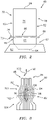
Fig. 2 is a schematic of an exemplary composite blade. -
Fig. 3 is a schematic of an exemplary composite blade in partial cross section. -
Fig. 4 is a Stress v Strain graphic representation of the performance of the exemplary composite blade with fuse. -
Fig. 5 is a Stress v Speed graphic representation of the performance of the exemplary composite blade with fuse. -
Figure 1 schematically illustrates agas turbine engine 20. Thegas turbine engine 20 is disclosed herein as a two-spool turbofan that generally incorporates afan section 22, acompressor section 24, acombustor section 26 and aturbine section 28. Thefan section 22 may include a single-stage fan 42 having a plurality offan blades 43. Thefan blades 43 may have a fixed stagger angle or may have a variable pitch to direct incoming airflow from an engine inlet. Thefan 42 drives air along a bypass flow path B in abypass duct 13 defined within ahousing 15 such as a fan case or nacelle, and also drives air along a core flow path C for compression and communication into thecombustor section 26 then expansion through theturbine section 28. Asplitter 29 aft of thefan 42 divides the air between the bypass flow path B and the core flow path C. Thehousing 15 may surround thefan 42 to establish an outer diameter of thebypass duct 13. Thesplitter 29 may establish an inner diameter of thebypass duct 13. Although depicted as a two-spool turbofan gas turbine engine in the disclosed nonlimiting embodiment, it should be understood that the concepts described herein are not limited to use with two-spool turbofans as the teachings may be applied to other types of turbine engines including three-spool architectures. Theengine 20 may incorporate a variable area fan nozzle for varying an exit area of the bypass flow path B and/or a thrust reverser for generating reverse thrust. - The
exemplary engine 20 generally includes alow speed spool 30 and ahigh speed spool 32 mounted for rotation about an engine central longitudinal axis A relative to an enginestatic structure 36 viaseveral bearing systems 38. It should be understood thatvarious bearing systems 38 at various locations may alternatively or additionally be provided, and the location ofbearing systems 38 may be varied as appropriate to the application. - The
low speed spool 30 generally includes aninner shaft 40 that interconnects, a first (or low)pressure compressor 44 and a first (or low)pressure turbine 46. Theinner shaft 40 is connected to thefan 42 through a speed change mechanism, which in the exemplarygas turbine engine 20 is illustrated as a gearedarchitecture 48 to drive thefan 42 at a lower speed than thelow speed spool 30. Theinner shaft 40 may interconnect thelow pressure compressor 44 andlow pressure turbine 46 such that thelow pressure compressor 44 andlow pressure turbine 46 are rotatable at a common speed and in a common direction. In other embodiments, thelow pressure turbine 46 drives both thefan 42 andlow pressure compressor 44 through the gearedarchitecture 48 such that thefan 42 andlow pressure compressor 44 are rotatable at a common speed. Although this application discloses gearedarchitecture 48, its teaching may benefit direct drive engines having no geared architecture. Thehigh speed spool 32 includes anouter shaft 50 that interconnects a second (or high)pressure compressor 52 and a second (or high)pressure turbine 54. Acombustor 56 is arranged in theexemplary gas turbine 20 between thehigh pressure compressor 52 and thehigh pressure turbine 54. Amid-turbine frame 57 of the enginestatic structure 36 may be arranged generally between thehigh pressure turbine 54 and thelow pressure turbine 46. Themid-turbine frame 57 further supports bearingsystems 38 in theturbine section 28. Theinner shaft 40 and theouter shaft 50 are concentric and rotate via bearingsystems 38 about the engine central longitudinal axis A which is collinear with their longitudinal axes. - Airflow in the core flow path C is compressed by the
low pressure compressor 44 then thehigh pressure compressor 52, mixed and burned with fuel in thecombustor 56, then expanded through thehigh pressure turbine 54 andlow pressure turbine 46. Themid-turbine frame 57 includesairfoils 59 which are in the core flow path C. Theturbines low speed spool 30 andhigh speed spool 32 in response to the expansion. It will be appreciated that each of the positions of thefan section 22,compressor section 24,combustor section 26,turbine section 28, and fandrive gear system 48 may be varied. For example,gear system 48 may be located aft of the low pressure compressor, or aft of thecombustor section 26 or even aft ofturbine section 28, andfan 42 may be positioned forward or aft of the location ofgear system 48. - The
low pressure compressor 44,high pressure compressor 52,high pressure turbine 54 andlow pressure turbine 46 each include one or more stages having a row of rotatable airfoils. Each stage may include a row of vanes adjacent the rotatable airfoils. The rotatable airfoils are schematically indicated at 47, and the vanes are schematically indicated at 49. - The
engine 20 may be a high-bypass geared aircraft engine. The bypass ratio can be greater than or equal to 10.0 and less than or equal to about 18.0, or more narrowly can be less than or equal to 16.0. The gearedarchitecture 48 may be an epicyclic gear train, such as a planetary gear system or a star gear system. The epicyclic gear train may include a sun gear, a ring gear, a plurality of intermediate gears meshing with the sun gear and ring gear, and a carrier that supports the intermediate gears. The sun gear may provide an input to the gear train. The ring gear (e.g., star gear system) or carrier (e.g., planetary gear system) may provide an output of the gear train to drive thefan 42. A gear reduction ratio may be greater than or equal to 2.3, or more narrowly greater than or equal to 3.0, and in some embodiments the gear reduction ratio is greater than or equal to 3.4. The gear reduction ratio may be less than or equal to 4.0. The fan diameter is significantly larger than that of thelow pressure compressor 44. Thelow pressure turbine 46 can have a pressure ratio that is greater than or equal to 8.0 and in some embodiments is greater than or equal to 10.0. The low pressure turbine pressure ratio can be less than or equal to 13.0, or more narrowly less than or equal to 12.0.Low pressure turbine 46 pressure ratio is pressure measured prior to an inlet oflow pressure turbine 46 as related to the pressure at the outlet of thelow pressure turbine 46 prior to an exhaust nozzle. It should be understood, however, that the above parameters are only exemplary of one embodiment of a geared architecture engine and that the present invention is applicable to other gas turbine engines including direct drive turbofans. All of these parameters are measured at the cruise condition described below. - A significant amount of thrust is provided by the bypass flow B due to the high bypass ratio. The
fan section 22 of theengine 20 is designed for a particular flight condition -- typically cruise at about 0.8 Mach and about 35,000 feet (10,668 meters). The flight condition of 0.8 Mach and 35,000 feet (10,668 meters), with the engine at its best fuel consumption - also known as "bucket cruise Thrust Specific Fuel Consumption ('TSFC')" - is the industry standard parameter of lbm of fuel being burned divided by lbf of thrust the engine produces at that minimum point. The engine parameters described above, and those in the next paragraph are measured at this condition unless otherwise specified. - "Fan pressure ratio" is the pressure ratio across the
fan blade 43 alone, without a Fan Exit Guide Vane ("FEGV") system. A distance is established in a radial direction between the inner and outer diameters of thebypass duct 13 at an axial position corresponding to a leading edge of thesplitter 29 relative to the engine central longitudinal axis A. The fan pressure ratio is a spanwise average of the pressure ratios measured across thefan blade 43 alone over radial positions corresponding to the distance. The fan pressure ratio can be less than or equal to 1.45, or more narrowly greater than or equal to 1.25, such as between 1.30 and 1.40. "Corrected fan tip speed" is the actual fan tip speed in ft/sec divided by an industry standard temperature correction of [(Tram °R) / (518.7 °R)]0.5. The "1 corrected fan tip speed" can be less than or equal to 1150.0 ft / second (350.5 meters/second), and greater than or equal to 1000.0 ft / second (304.8 meters/second). - Referring also to
Fig. 2 , ablade 60 is shown. Theblade 60 can be a ceramic matrix composite (CMC) gas turbine engine blade. Theblade 60 includes aroot portion 61 with aneck 62. Theneck 62 is not located in the hot working fluid flow path. Theblade 60 is coupled with aturbine disk 63 proximate theroot 61. Theneck 62 includes a base orfirst end 64 and asecond end 66 at an opposite side relative to thebase 64. The blade includes a platform region, specifically aplatform 68 disposed along an upper portion of theneck 62. Theplatform region 68 defines the flowpath that separates the hot working fluid from the cooler working fluid proximate theneck 62. Theplatform 68 can be attached to theblade 60 or does not have to be attached to theblade 60. The platform has afirst side 70 facing thesecond end 66 of theneck 62. Theblade 60 further includes anairfoil 72 supported on a second oropposite side 74 of theplatform 68 relative to theneck 62 and extending outwardly from theplatform 68. Theairfoil 72 includes aconcave side 76 and an oppositely facingconvex side 78. Theblade 60 includes anaxially leading edge 80, anaxially trailing edge 82, a radiallyouter side 84 and a radiallyinner side 86. - Referring also to
Fig. 3 , the cross section view of theblade 60 reveals thecomposite structure 88. Thecomposite structure 88 includes interior ply layers 90 that have varying shapes resulting in anexterior contour 92 of theblade 60 with outer ply layers 94 wrapping around the interior ply layers 90. Although a particularexterior contour 92 is shown inFig. 3 , another exterior contour for a different application would still fall within this disclosure. Although theblade 60 is illustrated, the disclosure applies to all types of components made from a composite material and is not limited to thecomposite blade 60 illustrated. - The ceramic
material composite blade 60 can be made up of thelayers unidirectional layup 96 is strongest when loaded in the zero direction (0 degree direction), and the weakest when loaded in the ninety degree direction (90 degree direction). The zerodegree direction 98 is along the radial direction, shown inFig. 3 that can include a range from -5 degrees to 0 degrees and/or 0 degrees to 5 degrees in the radial direction. The 90degree direction 100 is along the direction orthogonal and/or substantially orthogonal to the zerodegree direction 98, as shown coming out of the page. The 90 degree direction can range from 85 degrees to 95 degrees in a direction orthogonal/substantially orthogonal to the zero degree direction. - Referring also to
Figs. 4 and 5 , when loaded in the 0degree direction 98, the unidirectional material displays a definitive proportional limit and a much higher fracture limit. The proportional limit is the point on a stress-strain curve where the onset of significant matrix cracking occurs. The deformation up to the proportional limit is relatively linear, and load is carried both by the matrix and the ceramic fibers. As stress increases above the proportional limit, the matrix cracking increases. The applied load is transferred from the matrix to the ceramic fibers through the interface coating (IFC). This behavior is revealed in the stress-strain plot, as the slope of the stress-strain curve decreases, representing a decrease in the overall Young's Modulus. In other words, the proportional limit determines the greatest stress where the load is shared between the matrix and the fibers, with minimal matrix cracks. For components made from CMC, repetitive loading and unloading, to stress levels below the proportional limit (PL) will not result in significant permanent deformation of the component. - For loads that cause the CMC to exceed its PL stress, the onset of significant matrix cracking will result in some permanent deformation. This may be in the form of local fracture at stress concentrations (such as a hole or thickness change), at the region of a local curvature change, or local delamination of layers.
- CMCs made with 0 degree plies demonstrate the greatest load capability (fracture strength) after the proportional limit. The fracture of the matrix and load transfer through the interface coating, results in pure tension in the fibers. Thus the strength of the fibers, and the quantity of fibers in the 0 direction, known as fiber fraction, determine the fracture strength of that ply.
- CMC's made with 90 degree plies demonstrate the lowest proportional limit and virtually no additional load capability, such that fracture occurs near or slightly above the PL. Of the three major components of a CMC, matrix, fiber, and interface coating (IFC), the IFC coating is significantly the weakest. When load is applied to a 90 degree ply, the matrix carries the load, with minimal fiber loading through bonding between the fiber and the IFC. Once matrix cracking begins, the bond between the IFC and the fiber is overloaded and subsequently debonds, and removes any load path through the fiber. Since the matrix is the only portion of the CMC that is carrying the load, matrix cracking propagates quickly, leading to rapid fracture. In the case of 90 degree plies, an increase in fiber fraction lowers the PL, as there is less matrix to carry the load. Altering the fiber fraction in the 90 ply will directly change the fracture strength of the CMC.
- Fracture is the separation of an object or material into two or more pieces under the action of stress. When the
blade 60 is loaded in the 90degree direction 100, the unidirectional material can display a load to fracture, with no proportional limit. The magnitude of the fracture strength of the material can be much lower than the proportional limit of the 0direction 98 unidirectional material. The legend forFig. 5 includes the following: 100% = steady state redline; 1XX% = Max transient redline; 1XY% = load limit in fuse; 1XZ% = load limit blade; 1ZZ% = de-cobb event completed; 1OS% = overspeed w/o de-cobb. - The
blade 60 can be designed by aligning the layup of theunidirectional laminate material 96 to include a limiting section fuse or merely limitingsection 102 proximate theneck 62. The limitingsection 102 is shown schematically by a dashed line, however it is understood that the limitingsection 102 can cover a larger area within theblade 60 proximate theneck 62. In an exemplary embodiment, the limitingsection 102 can be located adjacent and just above theneck 62. The limitingsection 102 can be configured by aligningunidirectional material 96 at theinterior layers 90 in the 90degree direction 100 with respect to the 0degree direction 98. The advantage of the limitingsection 102 in theblade 60 is achieved because thetotal blade load 104 passes through thewhole blade 60 laminate with aportion 106 of thetotal blade load 104 passing through the limitingsection 102. Once the limitingsection 102 is overloaded, the limitingsection 102 cleanly breaks. Upon failure of the limitingsection 102, the remaininglaminate structure 94 proximate the limitingsection 102 takes up the total load. - At a predetermined speed (rpm), the
laminate structure 94 fractures. Since allblades 60 attached to thedisk 63 can be configured with the limitingsection fuse 102, allblades 60 are in a condition to fracture at the predetermined maximum speed. The predetermined maximum speed (rpm) can be set to be at or above the minimum required speed margin, such as defined by the (US) FAA in the Federal Airworthiness Regulations (FAR), Part 33.27. The limitingsection fuse 102 is configured to fracture at a load corresponding to a disk speed of 0 percent to 2 percent above the required five minute overspeed design point per aviation regulations with less than a two percent margin. The limitingsection fuse 102 can be configured to fracture at a load corresponding to a disk speed when the engine is fully assembled that is more than 120% but less than about 122% of the maximum rated speed for thedisk 63. Thedisk 63 is configured to withstand the required five minute overspeed design point per aviation regulations with less than two percent margin. Thedisk 63 can be configured such that thedisk 63 can withstand a load corresponding to a disk speed when the engine is fully assembled that less than about 122% of the maximum rated speed for thedisk 63 but cannot withstand a load corresponding to a disk speed when the engine is fully assembled that is greater than about 122% of the maximum rated speed for thedisk 63. Once oneblade 60 breaks free from thedisk 63, theblade 60 enters the flowpath of the remainder of theblades 60. The sudden impact of thefree blade 60 with theother blades 60 overloads the impactedblade 60. There is a cascadingblade 60 fracture event that follows theinitial blade 60 fracture. Once all theblades 60 de-cobb from thedisk 63, the spinning rotor cannot accelerate, due to the absence of the driving torque. TheCMC material blades 60 have no significant creep/stress rupture debit, especially proximate theneck 62 region of theblade 60, since theneck 62 is cooler. Thus the short term and long term strengths are similar. A section with some statistical distribution will result in a fracture at a predictable predetermined speed. The cascading de-cobb event can occur at the first limiting blade in thewhole disk 63. - The interior layers 90 include at least one 90
degree direction layer 106 and at least one zerodegree direction layer 108 in proximate relationship with each other. The at least one 90degree direction layer 106 can be made of the same material as the at least one zerodegree direction layer 108, or differing materials may be used to provide a localized stiffness discontinuity. The limitingsection fuse 102 defines an area of thecomposite blade 60 that is designed to fracture or fail at a lower force than the remaining portion of thecomposite blade 60. - The limiting
section 102 can include a fiber fraction of from 5% to 45%. In an exemplary embodiment, the limitingsection 102 can include a fiber fraction of from 35% to 45%. - In an exemplary embodiment, the
disk 63 is configured with a reduced design required for an overspeed capability. The term Burst Margin represents the relative rpm capability of the disk relative to the rated redline speed, defined here as 100% rpm, of a particular design. A disk that ruptures at 125% of redline speed is said to have a burst margin of 1.25. - The technical advantage of the exemplary composite blade with the fuse located proximate the neck includes a fuse located adjacent and above the neck of the root section.
- The technical advantage of the exemplary composite blade with the fuse located proximate the neck includes limitation on the maximum overspeed of the turbine disk.
- The technical advantage of the exemplary composite blade with the fuse located proximate the neck includes a turbine disk with reduced weight.
- The technical advantage of the exemplary composite blade with the fuse located proximate the neck includes a turbine disk with a reduced design required for an overspeed capability.
- The technical advantage of the exemplary composite blade with the fuse located proximate the neck includes a turbine engine disk with blades that are designed to de-cobb from the disk in a predictable manner, and at a speed range which is above the required transient redline speed but below the speed that would otherwise occur. Under shaft fracture scenarios, the maximum rotor speed possible is due to the aerodynamic gas load acting upon the blades, causing the rotor to accelerate to an rpm at which the blade torque is balanced with the aerodynamic losses caused by the flow thorough the blade row. For some turbines, without another means of limiting the overspeed, such as the fuel control software or mechanical limiter, the overspeed can exceed 150% of redline speed.
- There has been provided a composite blade with fuse. While the composite blade with fuse has been described in the context of specific embodiments thereof, other unforeseen alternatives, modifications, and variations may become apparent to those skilled in the art having read the foregoing description. Accordingly, it is intended to embrace those alternatives, modifications, and variations which fall within the broad scope of the appended claims.
Claims (15)
- A ceramic matrix composite gas turbine blade comprising:a root portion configured to be coupled to a disk, said root portion having a neck;a platform region disposed along an upper portion of the neck;an airfoil located opposite the neck and extends outwardly away from the neck; anda limiting section fuse formed in said blade proximate the neck.
- The ceramic matrix composite gas turbine blade according to claim 1, wherein said limiting section fuse comprises ceramic matrix composite material having interior ply layers aligned in a ninety degree direction with respect to outer ply layers aligned in a zero degree direction,
wherein said zero degree direction optionally comprises a range from negative 5 degrees to 5 degrees in a radial direction relative to the blade orientation in the gas turbine engine. - The ceramic matrix composite gas turbine blade according to claim 1 or 2, wherein said limiting section fuse is configured as unidirectional layup located in an area of the composite blade that is designed to fracture at a lower force than the remaining portion of the composite blade.
- The ceramic matrix composite gas turbine blade according to any preceding claim, wherein said limiting section fuse is configured to fracture at a predetermined speed of the disk.
- A process for reducing a burst margin in a gas turbine engine disk comprising:forming a gas turbine blade comprising a root portion coupled to said disk, said root portion having a neck; said blade including a platform between an airfoil portion and said root portion; andforming a limiting section fuse proximate the neck,wherein said limiting section fuse comprises composite material at interior ply layers aligned in a ninety degree direction with respect to outer ply layers aligned in a zero degree direction,wherein said zero degree direction comprises a range from 0 degrees to 5 degrees in a radial direction relative to the blade orientation in the gas turbine engine and said ninety degree direction is orthogonal to said zero degree direction.
- The process of claim 5, further comprising:
configuring said limiting section fuse as a unidirectional layup located in an area of the composite blade that is designed to fracture at a lower force than the remaining portion of the composite blade proximate the limiting section fuse. - The process of claim 5 or 6, further comprising:
configuring said limiting section fuse to fracture at a load corresponding to a disk speed of 0 percent to 2 percent above a required five minute overspeed design point per aviation regulations with less than a two percent margin. - The process of claim 5, 6 or 7, wherein said disk is configured to withstand a required five minute overspeed design point per aviation regulations with less than two percent margin.
- The ceramic matrix composite gas turbine blade of any of claims 1-4, or the process of any of claims 5-8, wherein said limiting section fuse is configured with a load to fracture with no proportional limit.
- The ceramic matrix composite gas turbine blade of any of claims 1-4 or 9, or the process of any claims 5-9, wherein said limiting section fuse comprises a fiber fraction of from 5% to 45%.
- A gas turbine engine comprising:a disk;a ceramic matrix composite blade coupled to the disk, said blade including:a root portion coupled to said disk, said root portion having a neck;a platform between an airfoil portion and said root portion; anda limiting section fuse proximate the neck,wherein said limiting section fuse comprises composite matrix material having interior ply layers aligned in a ninety degree direction with respect to outer ply layers aligned in a zero degree direction,wherein said zero degree direction optionally comprises a range from negative 5 degrees to 5 degrees in a radial direction relative to the blade orientation in the gas turbine engine.
- The gas turbine engine according to claim 11, wherein said limiting section fuse is configured as a unidirectional layup located in an area of the composite blade that is designed to fracture at a lower force than the remaining portion of the composite blade.
- The gas turbine engine according to claim 11 or 12, wherein said limiting section fuse is configured to fracture at a load corresponding to a disk speed when the engine is fully assembled that is more than 120% but less than about 122% of the maximum rated speed for the disk.
- The gas turbine engine according to claim 11, 12 or 13, wherein said disk is configured such that said disk can withstand a load corresponding to a disk speed when the engine is fully assembled that is less than about 122% of the maximum rated speed for the disk but cannot withstand a load corresponding to a disk speed when the engine is fully assembled that is greater than about 122% of the maximum rated speed for the disk.
- The gas turbine engine according to any of claims 11-14, wherein:said limiting section fuse comprises a fiber fraction of from 35% to 45%; and/orthe engine includes at least two composite blades coupled to the disk and wherein the limiting section fuses in the composite blades are configured to fracture at about the same disk speed.
Applications Claiming Priority (1)
| Application Number | Priority Date | Filing Date | Title |
|---|---|---|---|
| US17/124,981 US11492915B2 (en) | 2020-12-17 | 2020-12-17 | Turbine with reduced burst margin |
Publications (2)
| Publication Number | Publication Date |
|---|---|
| EP4015784A1 true EP4015784A1 (en) | 2022-06-22 |
| EP4015784B1 EP4015784B1 (en) | 2026-02-11 |
Family
ID=78957389
Family Applications (1)
| Application Number | Title | Priority Date | Filing Date |
|---|---|---|---|
| EP21215534.5A Active EP4015784B1 (en) | 2020-12-17 | 2021-12-17 | Ceramic matrix composite turbine blade with overspeed fuse |
Country Status (2)
| Country | Link |
|---|---|
| US (1) | US11492915B2 (en) |
| EP (1) | EP4015784B1 (en) |
Families Citing this family (2)
| Publication number | Priority date | Publication date | Assignee | Title |
|---|---|---|---|---|
| US11383494B2 (en) * | 2016-07-01 | 2022-07-12 | General Electric Company | Ceramic matrix composite articles having different localized properties and methods for forming same |
| DE102022204495A1 (en) * | 2022-05-06 | 2023-11-09 | Rolls-Royce Deutschland Ltd & Co Kg | Monitoring device and method for mechanical damage, in particular breakage, of a rotating shaft |
Citations (1)
| Publication number | Priority date | Publication date | Assignee | Title |
|---|---|---|---|---|
| US20120020789A1 (en) * | 2009-04-02 | 2012-01-26 | Turbomeca | Turbine wheel having de-tuned blades and including a damper device |
Family Cites Families (9)
| Publication number | Priority date | Publication date | Assignee | Title |
|---|---|---|---|---|
| DE102006049818A1 (en) * | 2006-10-18 | 2008-04-24 | Rolls-Royce Deutschland Ltd & Co Kg | Fan blade made of textile composite material |
| GB0707426D0 (en) | 2007-04-18 | 2007-05-23 | Rolls Royce Plc | Blade arrangement |
| US10174624B1 (en) * | 2014-06-05 | 2019-01-08 | United Technologies Corporation | Composite blade root lay-up |
| US9914282B2 (en) | 2014-09-05 | 2018-03-13 | United Technologies Corporation | Composite material with controlled fracture regions |
| EP3245386B1 (en) | 2015-01-13 | 2019-07-31 | General Electric Company | A composite airfoil with fuse architecture |
| US9850174B2 (en) * | 2016-03-23 | 2017-12-26 | General Electric Company | Ceramic matrix composites having monomodal pore size distribution and low fiber volume fraction |
| US10746045B2 (en) | 2018-10-16 | 2020-08-18 | General Electric Company | Frangible gas turbine engine airfoil including a retaining member |
| US11149558B2 (en) | 2018-10-16 | 2021-10-19 | General Electric Company | Frangible gas turbine engine airfoil with layup change |
| US20200141268A1 (en) | 2018-11-01 | 2020-05-07 | General Electric Company | Frangible Gas Turbine Engine Airfoil |
-
2020
- 2020-12-17 US US17/124,981 patent/US11492915B2/en active Active
-
2021
- 2021-12-17 EP EP21215534.5A patent/EP4015784B1/en active Active
Patent Citations (1)
| Publication number | Priority date | Publication date | Assignee | Title |
|---|---|---|---|---|
| US20120020789A1 (en) * | 2009-04-02 | 2012-01-26 | Turbomeca | Turbine wheel having de-tuned blades and including a damper device |
Non-Patent Citations (1)
| Title |
|---|
| GRUJICIC MICA ET AL: "Derivation, parameterization and validation of a creep deformation/rupture material constitutive model for SiC/SiC ceramic-matrix composites (CMCs)", vol. 3, no. 2, 18 May 2016 (2016-05-18), pages 591 - 619, XP055915772, ISSN: 2372-0484, Retrieved from the Internet <URL:http://dx.doi.org/10.3934/matersci.2016.2.591> [retrieved on 20220426], DOI: 10.3934/matersci.2016.2.591 * |
Also Published As
| Publication number | Publication date |
|---|---|
| US11492915B2 (en) | 2022-11-08 |
| US20220195876A1 (en) | 2022-06-23 |
| EP4015784B1 (en) | 2026-02-11 |
Similar Documents
| Publication | Publication Date | Title |
|---|---|---|
| US10436035B1 (en) | Fan design | |
| EP3415727B1 (en) | Gas turbine engine | |
| US20230383699A1 (en) | Gas turbine engine with power density range | |
| US20250389191A1 (en) | Efficient gas turbine engine installation and operation | |
| US10184483B2 (en) | Gas turbine engine airfoil | |
| US20130259653A1 (en) | Geared turbofan engine with power density range | |
| US10316757B2 (en) | Exhaust nozzle arrangement for geared turbofan | |
| US20130255275A1 (en) | Geared turbofan engine with power density range | |
| US20230323789A1 (en) | Gas turbine engine with third stream | |
| US12421903B2 (en) | Geared gas turbine engine | |
| EP4015784B1 (en) | Ceramic matrix composite turbine blade with overspeed fuse | |
| US20200408152A1 (en) | Gearbox and gas turbine propulsion unit | |
| US11473434B2 (en) | Gas turbine engine airfoil | |
| US11879383B2 (en) | Torque limiting device in a connection between a gearbox and a stationary structure in a gas turbine engine and a gas turbine engine | |
| CN112459923B (en) | Turbofan core and bypass arrangement | |
| EP3047109B1 (en) | Fan platform with leading edge tab | |
| US12421917B2 (en) | Gas turbine engine with third stream | |
| US12571358B2 (en) | Gas turbine engine with third stream | |
| US12352178B2 (en) | Turbine overspeed protection | |
| US20260043348A1 (en) | Gas Turbine Engine with Third Stream | |
| US20260043376A1 (en) | Gas Turbine Engine with Third Stream | |
| US20260043377A1 (en) | Gas Turbine Engine with Third Stream | |
| US20260043358A1 (en) | Gas Turbine Engine with Third Stream | |
| EP4553293A1 (en) | Strut for bearing assembly and method for removing strut | |
| WO2025259893A1 (en) | Gas turbine engine with third stream |
Legal Events
| Date | Code | Title | Description |
|---|---|---|---|
| PUAI | Public reference made under article 153(3) epc to a published international application that has entered the european phase |
Free format text: ORIGINAL CODE: 0009012 |
|
| STAA | Information on the status of an ep patent application or granted ep patent |
Free format text: STATUS: THE APPLICATION HAS BEEN PUBLISHED |
|
| AK | Designated contracting states |
Kind code of ref document: A1 Designated state(s): AL AT BE BG CH CY CZ DE DK EE ES FI FR GB GR HR HU IE IS IT LI LT LU LV MC MK MT NL NO PL PT RO RS SE SI SK SM TR |
|
| STAA | Information on the status of an ep patent application or granted ep patent |
Free format text: STATUS: REQUEST FOR EXAMINATION WAS MADE |
|
| 17P | Request for examination filed |
Effective date: 20221222 |
|
| RBV | Designated contracting states (corrected) |
Designated state(s): AL AT BE BG CH CY CZ DE DK EE ES FI FR GB GR HR HU IE IS IT LI LT LU LV MC MK MT NL NO PL PT RO RS SE SI SK SM TR |
|
| RAP3 | Party data changed (applicant data changed or rights of an application transferred) |
Owner name: RTX CORPORATION |
|
| GRAP | Despatch of communication of intention to grant a patent |
Free format text: ORIGINAL CODE: EPIDOSNIGR1 |
|
| STAA | Information on the status of an ep patent application or granted ep patent |
Free format text: STATUS: GRANT OF PATENT IS INTENDED |
|
| RIC1 | Information provided on ipc code assigned before grant |
Ipc: F01D 21/04 20060101AFI20250826BHEP |
|
| INTG | Intention to grant announced |
Effective date: 20250918 |
|
| GRAS | Grant fee paid |
Free format text: ORIGINAL CODE: EPIDOSNIGR3 |
|
| GRAA | (expected) grant |
Free format text: ORIGINAL CODE: 0009210 |
|
| STAA | Information on the status of an ep patent application or granted ep patent |
Free format text: STATUS: THE PATENT HAS BEEN GRANTED |
|
| AK | Designated contracting states |
Kind code of ref document: B1 Designated state(s): AL AT BE BG CH CY CZ DE DK EE ES FI FR GB GR HR HU IE IS IT LI LT LU LV MC MK MT NL NO PL PT RO RS SE SI SK SM TR |
|
| REG | Reference to a national code |
Ref country code: CH Ref legal event code: F10 Free format text: ST27 STATUS EVENT CODE: U-0-0-F10-F00 (AS PROVIDED BY THE NATIONAL OFFICE) Effective date: 20260211 Ref country code: GB Ref legal event code: FG4D |
|
| REG | Reference to a national code |
Ref country code: DE Ref legal event code: R096 Ref document number: 602021047650 Country of ref document: DE |
|
| REG | Reference to a national code |
Ref country code: IE Ref legal event code: FG4D |