EP4015664A1 - Refractory metal alloy - Google Patents
Refractory metal alloy Download PDFInfo
- Publication number
- EP4015664A1 EP4015664A1 EP21215165.8A EP21215165A EP4015664A1 EP 4015664 A1 EP4015664 A1 EP 4015664A1 EP 21215165 A EP21215165 A EP 21215165A EP 4015664 A1 EP4015664 A1 EP 4015664A1
- Authority
- EP
- European Patent Office
- Prior art keywords
- refractory metal
- alloy
- components
- component
- metal alloy
- Prior art date
- Legal status (The legal status is an assumption and is not a legal conclusion. Google has not performed a legal analysis and makes no representation as to the accuracy of the status listed.)
- Pending
Links
- 239000003870 refractory metal Substances 0.000 title claims abstract description 70
- 229910001092 metal group alloy Inorganic materials 0.000 title claims abstract description 53
- 229910052751 metal Inorganic materials 0.000 claims abstract description 53
- 239000002184 metal Substances 0.000 claims abstract description 50
- 229910052750 molybdenum Inorganic materials 0.000 claims abstract description 33
- 229910052804 chromium Inorganic materials 0.000 claims abstract description 22
- 229910052755 nonmetal Inorganic materials 0.000 claims abstract description 21
- 229910052758 niobium Inorganic materials 0.000 claims abstract description 19
- 229910052721 tungsten Inorganic materials 0.000 claims abstract description 17
- 229910052720 vanadium Inorganic materials 0.000 claims abstract description 16
- 229910052748 manganese Inorganic materials 0.000 claims abstract description 10
- 229910052727 yttrium Inorganic materials 0.000 claims abstract description 10
- 229910052719 titanium Inorganic materials 0.000 claims abstract description 9
- 229910052735 hafnium Inorganic materials 0.000 claims abstract description 5
- 229910052726 zirconium Inorganic materials 0.000 claims abstract description 5
- 229910052710 silicon Inorganic materials 0.000 claims description 30
- 239000010703 silicon Substances 0.000 claims description 28
- ZOXJGFHDIHLPTG-UHFFFAOYSA-N Boron Chemical compound [B] ZOXJGFHDIHLPTG-UHFFFAOYSA-N 0.000 claims description 22
- 229910052796 boron Inorganic materials 0.000 claims description 22
- ZOKXTWBITQBERF-UHFFFAOYSA-N Molybdenum Chemical compound [Mo] ZOKXTWBITQBERF-UHFFFAOYSA-N 0.000 claims description 19
- 239000011733 molybdenum Substances 0.000 claims description 19
- 229910052715 tantalum Inorganic materials 0.000 claims description 17
- 229910052742 iron Inorganic materials 0.000 claims description 4
- 229910045601 alloy Inorganic materials 0.000 description 46
- 239000000956 alloy Substances 0.000 description 46
- XUIMIQQOPSSXEZ-UHFFFAOYSA-N Silicon Chemical compound [Si] XUIMIQQOPSSXEZ-UHFFFAOYSA-N 0.000 description 25
- 239000007789 gas Substances 0.000 description 23
- 239000010955 niobium Substances 0.000 description 21
- 239000011651 chromium Substances 0.000 description 18
- 229910008423 Si—B Inorganic materials 0.000 description 15
- 150000002739 metals Chemical class 0.000 description 12
- 229910000555 a15 phase Inorganic materials 0.000 description 11
- 239000000463 material Substances 0.000 description 11
- 230000003647 oxidation Effects 0.000 description 9
- 238000007254 oxidation reaction Methods 0.000 description 9
- 238000010587 phase diagram Methods 0.000 description 9
- 238000005728 strengthening Methods 0.000 description 7
- 239000000203 mixture Substances 0.000 description 6
- 239000010953 base metal Substances 0.000 description 5
- 230000015572 biosynthetic process Effects 0.000 description 5
- 239000000446 fuel Substances 0.000 description 5
- 239000006104 solid solution Substances 0.000 description 4
- QVGXLLKOCUKJST-UHFFFAOYSA-N atomic oxygen Chemical compound [O] QVGXLLKOCUKJST-UHFFFAOYSA-N 0.000 description 3
- 230000000694 effects Effects 0.000 description 3
- 238000002844 melting Methods 0.000 description 3
- 230000008018 melting Effects 0.000 description 3
- 150000002843 nonmetals Chemical class 0.000 description 3
- 229910052760 oxygen Inorganic materials 0.000 description 3
- 239000001301 oxygen Substances 0.000 description 3
- VYZAMTAEIAYCRO-UHFFFAOYSA-N Chromium Chemical compound [Cr] VYZAMTAEIAYCRO-UHFFFAOYSA-N 0.000 description 2
- 229910015505 Mo5SiB2 Inorganic materials 0.000 description 2
- 239000000470 constituent Substances 0.000 description 2
- 230000003247 decreasing effect Effects 0.000 description 2
- 239000012535 impurity Substances 0.000 description 2
- JKQOBWVOAYFWKG-UHFFFAOYSA-N molybdenum trioxide Chemical compound O=[Mo](=O)=O JKQOBWVOAYFWKG-UHFFFAOYSA-N 0.000 description 2
- 230000009467 reduction Effects 0.000 description 2
- 230000003068 static effect Effects 0.000 description 2
- GUVRBAGPIYLISA-UHFFFAOYSA-N tantalum atom Chemical compound [Ta] GUVRBAGPIYLISA-UHFFFAOYSA-N 0.000 description 2
- DBGSRZSKGVSXRK-UHFFFAOYSA-N 1-[2-[5-[2-(2,3-dihydro-1H-inden-2-ylamino)pyrimidin-5-yl]-1,3,4-oxadiazol-2-yl]acetyl]-3,6-dihydro-2H-pyridine-4-carboxylic acid Chemical compound C1C(CC2=CC=CC=C12)NC1=NC=C(C=N1)C1=NN=C(O1)CC(=O)N1CCC(=CC1)C(=O)O DBGSRZSKGVSXRK-UHFFFAOYSA-N 0.000 description 1
- OKTJSMMVPCPJKN-UHFFFAOYSA-N Carbon Chemical compound [C] OKTJSMMVPCPJKN-UHFFFAOYSA-N 0.000 description 1
- 229910015501 Mo3Si Inorganic materials 0.000 description 1
- 229910000691 Re alloy Inorganic materials 0.000 description 1
- 238000005275 alloying Methods 0.000 description 1
- 238000005134 atomistic simulation Methods 0.000 description 1
- 229910052799 carbon Inorganic materials 0.000 description 1
- 230000008859 change Effects 0.000 description 1
- 239000007795 chemical reaction product Substances 0.000 description 1
- 238000002485 combustion reaction Methods 0.000 description 1
- 238000004891 communication Methods 0.000 description 1
- 230000006835 compression Effects 0.000 description 1
- 238000007906 compression Methods 0.000 description 1
- 238000010276 construction Methods 0.000 description 1
- RKTYLMNFRDHKIL-UHFFFAOYSA-N copper;5,10,15,20-tetraphenylporphyrin-22,24-diide Chemical group [Cu+2].C1=CC(C(=C2C=CC([N-]2)=C(C=2C=CC=CC=2)C=2C=CC(N=2)=C(C=2C=CC=CC=2)C2=CC=C3[N-]2)C=2C=CC=CC=2)=NC1=C3C1=CC=CC=C1 RKTYLMNFRDHKIL-UHFFFAOYSA-N 0.000 description 1
- 230000007613 environmental effect Effects 0.000 description 1
- 239000011159 matrix material Substances 0.000 description 1
- 230000007246 mechanism Effects 0.000 description 1
- 238000000034 method Methods 0.000 description 1
- 238000012986 modification Methods 0.000 description 1
- 230000004048 modification Effects 0.000 description 1
- YUSUJSHEOICGOO-UHFFFAOYSA-N molybdenum rhenium Chemical compound [Mo].[Mo].[Re].[Re].[Re] YUSUJSHEOICGOO-UHFFFAOYSA-N 0.000 description 1
- GUCVJGMIXFAOAE-UHFFFAOYSA-N niobium atom Chemical compound [Nb] GUCVJGMIXFAOAE-UHFFFAOYSA-N 0.000 description 1
- 239000007800 oxidant agent Substances 0.000 description 1
- 230000001590 oxidative effect Effects 0.000 description 1
- -1 refractory metals Chemical class 0.000 description 1
- 230000004044 response Effects 0.000 description 1
- XLYOFNOQVPJJNP-UHFFFAOYSA-N water Chemical compound O XLYOFNOQVPJJNP-UHFFFAOYSA-N 0.000 description 1
Images
Classifications
-
- C—CHEMISTRY; METALLURGY
- C22—METALLURGY; FERROUS OR NON-FERROUS ALLOYS; TREATMENT OF ALLOYS OR NON-FERROUS METALS
- C22C—ALLOYS
- C22C27/00—Alloys based on rhenium or a refractory metal not mentioned in groups C22C14/00 or C22C16/00
- C22C27/04—Alloys based on tungsten or molybdenum
-
- C—CHEMISTRY; METALLURGY
- C22—METALLURGY; FERROUS OR NON-FERROUS ALLOYS; TREATMENT OF ALLOYS OR NON-FERROUS METALS
- C22C—ALLOYS
- C22C30/00—Alloys containing less than 50% by weight of each constituent
Definitions
- a gas turbine engine typically includes a fan section, a compressor section, a combustor section and a turbine section. Air entering the compressor section is compressed and delivered into the combustion section where it is mixed with fuel and ignited to generate a high-speed exhaust gas flow. The high-speed exhaust gas flow expands through the turbine section to drive the compressor and the fan section.
- the compressor section typically includes low and high pressure compressors, and the turbine section includes low and high pressure turbines.
- Refractory metals typically have high melting points and are therefore an attractive choice for various applications within the gas turbine engine. Refractory metals can be alloyed with other elements in order to improve certain properties, such as oxidation resistance. However, there are unique challenges to creating refractory metal alloys with improved properties that are suitable for use in gas turbine engines.
- a refractory metal alloy (e.g. a refractory metal alloy comprised within a component as disclosed herein) according to an exemplary embodiment of this disclosure, among other possible things includes at least three metal components. At least one of the metal components is a refractory metal selected from the group of Mo, Nb, W, Ti, V, Cr, Mn, Y, Zr, Hf, Ta, Fe, Co, and Al.
- the refractory metal alloy also includes two nonmetal components.
- the refractory metal alloy comprises non-trace amounts of each of the metal components and each of the nonmetal components.
- the refractory metal includes molybdenum.
- the two nonmetal components are silicon and boron.
- the two nonmetal components together comprise at least 10 atomic percent of the refractory metal alloy.
- the at least three metal components are selected from the group of Mo, V, Ta, Cr, Nb, and W.
- the three metal components include Mo, Ta, and Cr.
- the at least three metal components are M 1 , M 2 , and M 3 . In some embodiments, the atomic percent of M 1 ⁇ M 2 ⁇ M 3 , and the atomic percent of M 1 ⁇ 50.
- M 1 is Mo
- one of M 2 and M 3 is Nb.
- one of M 2 and M 3 is W.
- a component according to an exemplary embodiment of this disclosure includes a refractory metal alloy (e.g. a refractory metal alloy as disclosed herein), including/comprising molybdenum, a second metal component M 2 , a third metal component M 3 , silicon, and boron.
- a refractory metal alloy e.g. a refractory metal alloy as disclosed herein
- molybdenum e.g. a refractory metal alloy as disclosed herein
- the atomic percent of the silicon and boron together is at least 10 atomic percent.
- M 2 and M 3 are refractory metals.
- M 2 and M 3 are selected from the group of Ta, Ti, Cr, V, Nb, W, Fe, Co, Al, Mn and Y.
- one of M 2 and M 3 is Nb.
- M 2 has a larger atomic volume than M 1 and M 3 has a smaller atomic volume than M 1 .
- the component also includes a fourth metal component.
- the second, third, and fourth metal components are selected from the group of V, Ta, Cr, Nb, and W.
- the atomic percent of the silicon and boron together is at least 20 atomic percent.
- the component is a component of a gas turbine engine.
- the alloy as disclosed herein may comprise or consist of the listed elements/components, optionally with the usual or non-incidental impurities.
- the alloy as disclosed herein comprises the listed (non-Mo) elements/components and the balance Mo, optionally with the usual or non-incidental impurities.
- FIG. 1 schematically illustrates a gas turbine engine 20.
- the gas turbine engine 20 is disclosed herein as a two-spool turbofan that generally incorporates a fan section 22, a compressor section 24, a combustor section 26 and a turbine section 28.
- the fan section 22 drives air along a bypass flow path B in a bypass duct defined within a nacelle 15, and also drives air along a core flow path C for compression and communication into the combustor section 26 then expansion through the turbine section 28.
- FIG. 1 schematically illustrates a gas turbine engine 20.
- the gas turbine engine 20 is disclosed herein as a two-spool turbofan that generally incorporates a fan section 22, a compressor section 24, a combustor section 26 and a turbine section 28.
- the fan section 22 drives air along a bypass flow path B in a bypass duct defined within a nacelle 15, and also drives air along a core flow path C for compression and communication into the combustor section 26 then expansion through the turbine section 28.
- FIG. 1 schematic
- the exemplary engine 20 generally includes a low speed spool 30 and a high speed spool 32 mounted for rotation about an engine central longitudinal axis A relative to an engine static structure 36 via several bearing systems 38. It should be understood that various bearing systems 38 at various locations may alternatively or additionally be provided, and the location of bearing systems 38 may be varied as appropriate to the application.
- the low speed spool 30 generally includes an inner shaft 40 that interconnects, a first (or low) pressure compressor 44 and a first (or low) pressure turbine 46.
- the inner shaft 40 is connected to the fan 42 through a speed change mechanism, which in exemplary gas turbine engine 20 is illustrated as a geared architecture 48 to drive a fan 42 at a lower speed than the low speed spool 30.
- the high speed spool 32 includes an outer shaft 50 that interconnects a second (or high) pressure compressor 52 and a second (or high) pressure turbine 54.
- a combustor 56 is arranged in exemplary gas turbine 20 between the high pressure compressor 52 and the high pressure turbine 54.
- a mid-turbine frame 57 of the engine static structure 36 may be arranged generally between the high pressure turbine 54 and the low pressure turbine 46.
- the mid-turbine frame 57 further supports bearing systems 38 in the turbine section 28.
- the inner shaft 40 and the outer shaft 50 are concentric and rotate via bearing systems 38 about the engine central longitudinal axis A which is colline
- the core airflow is compressed by the low pressure compressor 44 then the high pressure compressor 52, mixed and burned with fuel in the combustor 56, then expanded through the high pressure turbine 54 and low pressure turbine 46.
- the mid-turbine frame 57 includes airfoils 59 which are in the core airflow path C.
- the low pressure turbine 46 incudes airfoils 60.
- the turbines 46, 54 rotationally drive the respective low speed spool 30 and high speed spool 32 in response to the expansion.
- gear system 48 may be varied.
- gear system 48 may be located aft of the low pressure compressor, or aft of the combustor section 26 or even aft of turbine section 28, and fan 42 may be positioned forward or aft of the location of gear system 48.
- the engine 20 in one example is a high-bypass geared aircraft engine.
- the engine 20 bypass ratio is greater than about six (6), with an example embodiment being greater than about ten (10)
- the geared architecture 48 is an epicyclic gear train, such as a planetary gear system or other gear system, with a gear reduction ratio of greater than about 2.3
- the low pressure turbine 46 has a pressure ratio that is greater than about five.
- the engine 20 bypass ratio is greater than about ten (10:1)
- the fan diameter is significantly larger than that of the low pressure compressor 44
- the low pressure turbine 46 has a pressure ratio that is greater than about five 5:1.
- Low pressure turbine 46 pressure ratio is pressure measured prior to inlet of low pressure turbine 46 as related to the pressure at the outlet of the low pressure turbine 46 prior to an exhaust nozzle.
- the geared architecture 48 may be an epicycle gear train, such as a planetary gear system or other gear system, with a gear reduction ratio of greater than about 2.3:1 and less than about 5:1. It should be understood, however, that the above parameters are only exemplary of one embodiment of a geared architecture engine and that the present invention is applicable to other gas turbine engines including direct drive turbofans.
- the fan section 22 of the engine 20 is designed for a particular flight condition -- typically cruise at about 0.8 Mach and about 35,000 feet (10,668 meters).
- the flight condition of 0.8 Mach and 35,000 ft (10,668 meters), with the engine at its best fuel consumption - also known as "bucket cruise Thrust Specific Fuel Consumption ('TSFC')" - is the industry standard parameter of lbm of fuel being burned divided by lbf of thrust the engine produces at that minimum point.
- "Low fan pressure ratio” is the pressure ratio across the fan blade alone, without a Fan Exit Guide Vane (“FEGV”) system.
- the low fan pressure ratio as disclosed herein according to one non-limiting embodiment is less than about 1.45.
- Low corrected fan tip speed is the actual fan tip speed in ft/sec divided by an industry standard temperature correction of [(Tram °R) / (518.7 °R)] ⁇ 0.5.
- the "Low corrected fan tip speed” as disclosed herein according to one non-limiting embodiment is less than about 1150 ft / second (350.5 meters/second).
- Gas turbine engines include harsh environments and therefore there is a need for materials with high temperature capability, high strength balanced with sufficient ductility, and good oxidation resistance.
- the materials described herein can be used in various gas turbine engine 20 components described above, such as in the combustor section 26, or in the turbine/compressor sections 28/24.
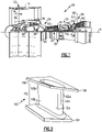
- Figure 2 shows one non-limiting example component comprising the material described herein, which is a representative airfoil 100 used in the turbine engine 20 (see also Figure 1 ).
- the airfoil 100 is a turbine vane; however, it is to be understood that, although the examples herein may be described and shown with reference to turbine vanes, this disclosure is also applicable to blades.
- the description herein is applicable to other types of gas turbine engine 20 components, and is not limited to airfoils.
- the material composition described herein could be used for applications other than gas turbine engines.
- the airfoil 100 includes an airfoil section 102 that delimits an aerodynamic profile.
- Airfoil section 102 defines a leading end 102a, a trailing end 102b, and first and second sides 102c/102d that join the leading end 102a and the trailing end 102b.
- first and second as used herein is to differentiate that there are two architecturally distinct components or features. It is to be further understood that the terms “first” and “second” are interchangeable in the embodiments herein in that a first component or feature could alternatively be termed as the second component or feature, and vice versa.
- the first side 102c is a pressure side
- the second side 102d is a suction side.
- the airfoil section 102 generally extends in a radial direction relative to the central engine axis A.
- the airfoil section 102 spans from a first or inner platform 104 to a second or outer platform 106.
- the terms “inner” and “outer” refer to location with respect to the central engine axis A, i.e., radially inner or radially outer.
- the airfoil section 102 would extend from a single inner platform to a free end.
- the airfoil piece would include only the airfoil section 102 and platform 104.
- the airfoil piece is formed of a single, continuous wall 108 that defines the complete or substantially complete shape and contour of the airfoil section 102 and platforms 104/106.
- the airfoil 100 is a unibody construction.
- Molybdenum is known to have a high melting point and good temperature resistance properties. However, molybdenum is susceptible to environmental attack, such as oxidation. Alloying molybdenum with silicon and boron improves the oxidation resistance of the molybdenum.
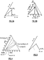
- Figure 3a shows a schematic phase diagram of the Mo-rich region of a Mo-Si-B alloy.
- Figure 3b shows a phase diagram of the Mo-rich region of a Mo-Si-B alloy at 1600 degrees C. As shown in Figures 3a-b , three phases are present: a body-centered-cubic (BCC)-Mo phase, Mo 5 SiB 2 (known as T2), and Mo 3 Si (known as A15).
- BCC body-centered-cubic
- T2 Mo 5 SiB 2
- A15 Mo 3 Si
- the BCC-Mo is primarily composed of Mo, but can contain a few atomic % Si (e.g,, less than 3 atomic %) under certain conditions and less amounts of B.
- the BCC-Mo phase contributes to the ductility of the alloy, and alloys having at least 50 volume percent BCC-Mo have satisfactory ductility for use in harsh environments such as a gas turbine engine 20.
- the dashed line represents the range of alloy composition that have 50 volume percent BCC-Mo.
- the BCC phase can have limited creep resistance at elevated temperatures.
- the T2 and A15 phases contribute to the strength of the alloy. Thus the combination of BCC phase(s) and strengthening phase(s) such as T2 and A15 are needed to provide an alloy satisfactory for harsh environments.
- Silicon and boron contribute to the oxidation resistance for the Mo-Si-B alloy.
- the oxidation resistance stems from the fact that the silicon and boron are reactive with oxygen, and the reaction products (e.g., borosilicate oxide scale) limit the transport of oxidants (e.g. oxygen and water vapor) to the alloy, thus dramatically decreasing the rate at which the alloy reacts with oxygen.
- the reaction products e.g., borosilicate oxide scale
- oxidants e.g. oxygen and water vapor
- increasing the atomic percent of silicon and boron increases the amount of A15 phase while decreasing the amount of BCC-Mo phase. Therefore, an alloy with a significant atomic percent of silicon may have insufficient ductility.
- the A15 phase has a high Mo:Si ratio (3:1) and a molar volume comparable to BCC-Mo, which results in the ratio of atomic concentration of Si in the bulk alloy to volume of A15 to be low (e.g., much of the silicon tends to be found in the A15 phase).
- Table 1 below shows compositions of five example Mo-Si-B alloys, each having a volume % of BCC-Mo equal to 50.0. As shown in the table, alloys with more silicon tend to form large amounts of the A15 phase.
- Example E has 7.5 atomic % Si and 5.4 volume % A15 phase. But increasing the atomic % of Si to 11.8 in Example A drastically increases the volume % of the A15 phase to 41.6.
- Example A 85.7 11.8 2.5 14.3 4.72 50.0 41.6 8.4
- Example B 84.3 10.7 5.0 15.7 2.15 50.0 33.0 17.0
- Example C 82.8 9.7 7.5 17.2 1.29 50.0 24.1 25.9
- Disrupting the formation of the A15 phase would produce an alloy with improved mechanical and oxidation resistance properties by allowing for more silicon and boron to be added without reducing/eliminating the ductile BCC-Mo phase.
- One way to disrupt the formation of the A15 phase is to add additional metals to the alloy.
- a phase diagram for the Mo-Nb-rich region of a Mo-Nb-Si-B alloy at 1500 degrees C is shown in Figure 4 .
- this alloy forms a T1 phase rather than the A15 phase, which contributes to the strength of the alloy.
- the T1 phase has a body-center tetragonal structure, and in this example is (Mo,Nb) 5 Si 3 .
- the combination of strengthening phases and ductile phases provide an improved material for gas turbine engine and other applications.
- the strengthening phases can vary depending on the alloy. For instance, some alloys can have more than one T1 phase, depending on the number of metals present in the alloy. For example, the Mo-Nb-Si-B alloy discussed above may have four phrases, a BCC phase, a Mo-rich T1 phase, a Nb-rich T1 phase, and T2. Likewise, some alloys can have more than one boride- and/or silicon-containing phase such as A15 in the example discussed above. Other alloys will also have different BCC phases, depending on the metal(s) present. The formation of one or more T1 phases, again depending on the metal(s) present, disrupts the formation of silicon-rich phases like A15, which allows the ratio of the Si concentration in the alloy to the Si concentration in the T1 phase to be higher.
- Figure 5 shows a schematic phase diagram for an example X-Si-B alloy, where X is a combination of metals "X" represents the non-Si and non-B constituents of the alloy, e.g., the metallic constituents of the alloy, and could include two or more metals.
- X would represent Mo and Nb.
- Table 2 shows compositions of five example X-Si-B alloys, each having an approximated volume % of BCC phase equal to 50.0.
- the dashed line represents the range of alloy composition that have 50.0 volume percent BCC-X.
- Example A 80.2 17.3 2.5 19.8 6.91 50.0 41.5 8.5
- Example B 80.0 15.0 5.0 20.0 3.00 50.0 32.9 17.1
- Example C 79.8 12.7 7.5 20.2 1.70 50.0 23.9 26.1
- Example D 79.5 10.5 10.0 20.5 1.05 50.0 14.8 35.2
- Example E 79.3 8.2 12.5 20.7 0.66 50.0 5.3 44.7
- Adding two or more metals, such as refractory metals, to the Mo-Si-B alloy further improves the properties of the material beyond those properties of a system that comprises only one additional metal.
- Refractory metals in particular easily crystallize into the BCC structure over a wide temperature range (in some cases, from room temperature up to the melting point).
- Ta, Ti, Cr, V, Nb, W, and Y all provide systems with a stable T1 phase.
- Nb, W, and Y in particular provide systems with an unstable T2 phase.
- Adding two or more metals to the Mo-Si-B system improves the oxidation resistance of the resulting material and also contributes to the strength of the BCC phase(s) by providing solid solution strengthening, and therefore contributes to the strength of the resulting material as compared to prior art refractory metal alloys.
- the magnitude of the solid solution strengthening can be increased when metals are added that have apparent atomic volumes that differ from the apparent atomic volume of the base metal.
- apparent atomic volume can be approximated for the BCC phase of each metallic element.
- Apparent atomic volume can be approximated by any known method. In one example, if the element is BCC, apparent atomic volume is approximated as A 3 /2, where A is the known lattice parameter taken from any known reference.
- average apparent atomic volume can be approximated by extrapolating from a high-temperature BCC form of the element.
- the average apparent atomic volume can be approximated from atomistic simulations.
- the solid solution strengthening effect is most pronounced when elements having a different size from the base metal are included in the alloy. For example, two elements are added with atomic volumes that are higher and lower, respectively, than the base metal. It has been proposed that the misfit solutes (e.g., those with different sizes than the base metal) inhibit the motion of edge-dislocation.
- a list of apparent atomic volumes for elements in a BCC lattice are given in Table 3 below. Additionally, the presence of additional metals can limit the activity of metals that form volatile oxides, such as Mo, which oxidizes to MoO 3 and W, which oxidizes to WO 3 .
- the additional metals can be selected to optimize the mechanical properties (e.g., strength and ductility) of the material while maximizing the oxidation resistance of the material.
- one or more components of the airfoil 100 such as the wall 108 comprises a refractory metal alloy.
- the wall 108 may be exposed to a temperature gradient during operation of the gas turbine engine 20 because air traveling inside the wall 108 may be cooler than air traveling outside the wall 108. Therefore, the wall 108 should be comprised of a material that has good temperature resistance, among other qualities that will be discussed in more detail below.
- the refractory metal alloy includes at least five atomic components. Each of the components comprises non-trace amounts of the refractory metal alloy, e.g., each of the five components makes up at least 5 atomic percent of the refractory metal alloy. Additionally, no single atomic component makes up greater than 50 atomic of the refractory metal alloy. "Atomic percent" refers to the percent of atoms in the refractory metal alloy, and therefore differs from weight percent or volume percent (though it may be related to weight/volume percent, in some examples).
- the refractory metal alloy includes at least three metallic components. At least two of the metallic components are refractory metals, though in some examples, all of the metallic components are refractory metals.
- the refractory metals could be Mo, Nb, W, Ti, V, Cr, Mn, Fe, Co, Y, Zr, Hf, or Ta. Molybdenum-Rhenium alloys tend to form a brittle sigma phase instead of the ductile BCC phase.
- An example refractory metal alloy has at least three metal components M 1 , M 2 , and M 3 , where the atomic percent of M 1 ⁇ M 2 ⁇ M 3 .
- the atomic percent of M 1 is less than or equal to 50%.
- the atomic percent of M 3 is greater than 10%.
- one of M 1 , M 2 , and M 3 is molybdenum.
- M 1 is molybdenum.
- M 2 is niobium, which is known to have high strength.
- M 2 has a larger apparent atomic volume than M 1
- M 3 has a smaller apparent atomic volume than M 1
- example options for M 1 , M 2 , and M 3 metals are shown in Table 3, above. As noted above, a solid solution strengthening effect is most pronounced when two elements (M 2 and M 3 ) are added with atomic volumes that are higher and lower, respectively, than the base metal (in this case, M 1 ).
- refractory metal alloy has four metallic components. More particularly, the metallic components are refractory metal alloys selected from the group of Mo, V, Ta, Cr, Nb, and W, wherein Mo comprises at least 15 atomic percent of the alloy. In one example, the refractory metal alloy includes Mo, Ta, and Cr along with a fourth metal selected from the foregoing group. Tantalum and chromium can contribute to the oxidative stability of the alloy because tantalum and chromium can selectively oxidize to form TaCrO 4 .
- the sum of the two non-metal components is at least 10 atomic percent. In a further example, the sum of the two non-metal components is at least 15 atomic percent. In a further example, the sum of the two non-metal components is between 15 and 20 atomic percent. In a particular example, the non-metal components are silicon and boron. In a further example, the refractory metal alloy includes at least 10 atomic percent silicon, and less than 10 atomic percent boron. In a more particular example, the refractory metal alloy includes 10 atomic percent silicon and 5 atomic percent boron.
- the refractory metal alloy has at least three phases.
- One of the phases is a BCC phase that forms a percolating continuous matrix in the refractory metal alloy.
- one of the remaining two phases is Mo 5 SiB 2 .
- Table 4 shows the atomic composition of some specific example refractory metal alloys according to the foregoing description: Table 4 Si B Mo w Nb V Ta Cr Atomic % Example 1 15 5 45 20 15 0 0 0 Example 2 10 10 45 20 15 0 0 0 Example 3 8 12 45 20 15 0 0 0 Example 4 15 5 20 20 0 0 20 20 Example 5 20 5 45 20 10 0 0 0 Example 6 15 5 30 20 15 0 15 15 15 15 15 15 15 15 15 15 15 15
Landscapes
- Chemical & Material Sciences (AREA)
- Engineering & Computer Science (AREA)
- Materials Engineering (AREA)
- Mechanical Engineering (AREA)
- Metallurgy (AREA)
- Organic Chemistry (AREA)
- Turbine Rotor Nozzle Sealing (AREA)
Abstract
Description
- A gas turbine engine typically includes a fan section, a compressor section, a combustor section and a turbine section. Air entering the compressor section is compressed and delivered into the combustion section where it is mixed with fuel and ignited to generate a high-speed exhaust gas flow. The high-speed exhaust gas flow expands through the turbine section to drive the compressor and the fan section. The compressor section typically includes low and high pressure compressors, and the turbine section includes low and high pressure turbines.
- Refractory metals typically have high melting points and are therefore an attractive choice for various applications within the gas turbine engine. Refractory metals can be alloyed with other elements in order to improve certain properties, such as oxidation resistance. However, there are unique challenges to creating refractory metal alloys with improved properties that are suitable for use in gas turbine engines.
- A refractory metal alloy (e.g. a refractory metal alloy comprised within a component as disclosed herein) according to an exemplary embodiment of this disclosure, among other possible things includes at least three metal components. At least one of the metal components is a refractory metal selected from the group of Mo, Nb, W, Ti, V, Cr, Mn, Y, Zr, Hf, Ta, Fe, Co, and Al. The refractory metal alloy also includes two nonmetal components. The refractory metal alloy comprises non-trace amounts of each of the metal components and each of the nonmetal components.
- In some embodiments, the refractory metal includes molybdenum.
- In some embodiments, the two nonmetal components are silicon and boron.
- In some embodiments, the two nonmetal components together comprise at least 10 atomic percent of the refractory metal alloy.
- In some embodiments, the at least three metal components are selected from the group of Mo, V, Ta, Cr, Nb, and W.
- In some embodiments, the three metal components include Mo, Ta, and Cr.
- In some embodiments, the at least three metal components are M1, M2, and M3. In some embodiments, the atomic percent of M1 ≥ M2 ≥ M3, and the atomic percent of M1 < 50.
- In some embodiments, M1 is Mo.
- In some embodiments, one of M2 and M3 is Nb.
- In some embodiments, one of M2 and M3 is W.
- A component according to an exemplary embodiment of this disclosure, among other possible things includes a refractory metal alloy (e.g. a refractory metal alloy as disclosed herein), including/comprising molybdenum, a second metal component M2, a third metal component M3, silicon, and boron. The atomic percent of molybdenum ≥ M2 ≥ M3, and the atomic percent of molybdenum < 50.
- In some embodiments, the atomic percent of the silicon and boron together is at least 10 atomic percent.
- In some embodiments, M2 and M3 are refractory metals.
- In some embodiments, M2 and M3 are selected from the group of Ta, Ti, Cr, V, Nb, W, Fe, Co, Al, Mn and Y.
- In some embodiments, one of M2 and M3 is Nb.
- In some embodiments, M2 has a larger atomic volume than M1 and M3 has a smaller atomic volume than M1.
- In some embodiments, the component also includes a fourth metal component.
- In some embodiments, the second, third, and fourth metal components are selected from the group of V, Ta, Cr, Nb, and W.
- In some embodiments, the atomic percent of the silicon and boron together is at least 20 atomic percent.
- In some embodiments, the component is a component of a gas turbine engine.
- The alloy as disclosed herein may comprise or consist of the listed elements/components, optionally with the usual or non-incidental impurities. In some embodiments, the alloy as disclosed herein comprises the listed (non-Mo) elements/components and the balance Mo, optionally with the usual or non-incidental impurities.
- The various features and advantages of the present disclosure will become apparent to those skilled in the art from the following detailed description. The drawings that accompany the detailed description can be briefly described as follows.
-
Figure 1 illustrates an example gas turbine engine. -
Figure 2 illustrates an example component for the gas turbine engine ofFigure 1 . -
Figure 3a illustrates a schematic phase diagram for a Mo-Si-B alloy. -
Figure 3b illustrates a phase diagram for a Mo-Si-B alloy at 1600 degrees C. -
Figure 4 illustrates a phase diagram for an Mo-Nb-Si-B alloy. -
Figure 5 illustrates a schematic phase diagram for an example X-Si-B alloy, where X is a combination of metals. -
Figure 1 schematically illustrates agas turbine engine 20. Thegas turbine engine 20 is disclosed herein as a two-spool turbofan that generally incorporates a fan section 22, acompressor section 24, acombustor section 26 and aturbine section 28. The fan section 22 drives air along a bypass flow path B in a bypass duct defined within anacelle 15, and also drives air along a core flow path C for compression and communication into thecombustor section 26 then expansion through theturbine section 28. Although depicted as a two-spool turbofan gas turbine engine in the disclosed non-limiting embodiment, it should be understood that the concepts described herein are not limited to use with two-spool turbofans as the teachings may be applied to other types of turbine engines including three-spool architectures. - The
exemplary engine 20 generally includes alow speed spool 30 and ahigh speed spool 32 mounted for rotation about an engine central longitudinal axis A relative to an enginestatic structure 36 viaseveral bearing systems 38. It should be understood thatvarious bearing systems 38 at various locations may alternatively or additionally be provided, and the location ofbearing systems 38 may be varied as appropriate to the application. - The
low speed spool 30 generally includes aninner shaft 40 that interconnects, a first (or low)pressure compressor 44 and a first (or low)pressure turbine 46. Theinner shaft 40 is connected to thefan 42 through a speed change mechanism, which in exemplarygas turbine engine 20 is illustrated as a gearedarchitecture 48 to drive afan 42 at a lower speed than thelow speed spool 30. Thehigh speed spool 32 includes anouter shaft 50 that interconnects a second (or high) pressure compressor 52 and a second (or high)pressure turbine 54. Acombustor 56 is arranged inexemplary gas turbine 20 between the high pressure compressor 52 and thehigh pressure turbine 54. Amid-turbine frame 57 of the enginestatic structure 36 may be arranged generally between thehigh pressure turbine 54 and thelow pressure turbine 46. Themid-turbine frame 57 further supports bearingsystems 38 in theturbine section 28. Theinner shaft 40 and theouter shaft 50 are concentric and rotate viabearing systems 38 about the engine central longitudinal axis A which is collinear with their longitudinal axes. - The core airflow is compressed by the
low pressure compressor 44 then the high pressure compressor 52, mixed and burned with fuel in thecombustor 56, then expanded through thehigh pressure turbine 54 andlow pressure turbine 46. Themid-turbine frame 57 includesairfoils 59 which are in the core airflow path C. Thelow pressure turbine 46incudes airfoils 60. Theturbines low speed spool 30 andhigh speed spool 32 in response to the expansion. It will be appreciated that each of the positions of the fan section 22,compressor section 24,combustor section 26,turbine section 28, and fandrive gear system 48 may be varied. For example,gear system 48 may be located aft of the low pressure compressor, or aft of thecombustor section 26 or even aft ofturbine section 28, andfan 42 may be positioned forward or aft of the location ofgear system 48. - The
engine 20 in one example is a high-bypass geared aircraft engine. In a further example, theengine 20 bypass ratio is greater than about six (6), with an example embodiment being greater than about ten (10), the gearedarchitecture 48 is an epicyclic gear train, such as a planetary gear system or other gear system, with a gear reduction ratio of greater than about 2.3 and thelow pressure turbine 46 has a pressure ratio that is greater than about five. In one disclosed embodiment, theengine 20 bypass ratio is greater than about ten (10:1), the fan diameter is significantly larger than that of thelow pressure compressor 44, and thelow pressure turbine 46 has a pressure ratio that is greater than about five 5:1.Low pressure turbine 46 pressure ratio is pressure measured prior to inlet oflow pressure turbine 46 as related to the pressure at the outlet of thelow pressure turbine 46 prior to an exhaust nozzle. The gearedarchitecture 48 may be an epicycle gear train, such as a planetary gear system or other gear system, with a gear reduction ratio of greater than about 2.3:1 and less than about 5:1. It should be understood, however, that the above parameters are only exemplary of one embodiment of a geared architecture engine and that the present invention is applicable to other gas turbine engines including direct drive turbofans. - A significant amount of thrust is provided by the bypass flow B due to the high bypass ratio. The fan section 22 of the
engine 20 is designed for a particular flight condition -- typically cruise at about 0.8 Mach and about 35,000 feet (10,668 meters). The flight condition of 0.8 Mach and 35,000 ft (10,668 meters), with the engine at its best fuel consumption - also known as "bucket cruise Thrust Specific Fuel Consumption ('TSFC')" - is the industry standard parameter of lbm of fuel being burned divided by lbf of thrust the engine produces at that minimum point. "Low fan pressure ratio" is the pressure ratio across the fan blade alone, without a Fan Exit Guide Vane ("FEGV") system. The low fan pressure ratio as disclosed herein according to one non-limiting embodiment is less than about 1.45. "Low corrected fan tip speed" is the actual fan tip speed in ft/sec divided by an industry standard temperature correction of [(Tram °R) / (518.7 °R)]^0.5. The "Low corrected fan tip speed" as disclosed herein according to one non-limiting embodiment is less than about 1150 ft / second (350.5 meters/second). - Gas turbine engines include harsh environments and therefore there is a need for materials with high temperature capability, high strength balanced with sufficient ductility, and good oxidation resistance. The materials described herein can be used in various
gas turbine engine 20 components described above, such as in thecombustor section 26, or in the turbine/compressor sections 28/24.Figure 2 shows one non-limiting example component comprising the material described herein, which is arepresentative airfoil 100 used in the turbine engine 20 (see alsoFigure 1 ). As shown, theairfoil 100 is a turbine vane; however, it is to be understood that, although the examples herein may be described and shown with reference to turbine vanes, this disclosure is also applicable to blades. Moreover, it should be understood that the description herein is applicable to other types ofgas turbine engine 20 components, and is not limited to airfoils. Additionally, the material composition described herein could be used for applications other than gas turbine engines. - In the illustrated example, the
airfoil 100 includes anairfoil section 102 that delimits an aerodynamic profile.Airfoil section 102 defines aleading end 102a, a trailingend 102b, and first andsecond sides 102c/102d that join theleading end 102a and the trailingend 102b. The terminology "first" and "second" as used herein is to differentiate that there are two architecturally distinct components or features. It is to be further understood that the terms "first" and "second" are interchangeable in the embodiments herein in that a first component or feature could alternatively be termed as the second component or feature, and vice versa. In this example, thefirst side 102c is a pressure side and thesecond side 102d is a suction side. Theairfoil section 102 generally extends in a radial direction relative to the central engine axis A. For a vane, theairfoil section 102 spans from a first orinner platform 104 to a second orouter platform 106. The terms "inner" and "outer" refer to location with respect to the central engine axis A, i.e., radially inner or radially outer. For a blade, theairfoil section 102 would extend from a single inner platform to a free end. - The
airfoil section 102 andplatforms 104/106 together constitute an airfoil piece. For a blade, the airfoil piece would include only theairfoil section 102 andplatform 104. In one example, the airfoil piece is formed of a single,continuous wall 108 that defines the complete or substantially complete shape and contour of theairfoil section 102 andplatforms 104/106. In this regard, theairfoil 100 is a unibody construction. - Molybdenum is known to have a high melting point and good temperature resistance properties. However, molybdenum is susceptible to environmental attack, such as oxidation. Alloying molybdenum with silicon and boron improves the oxidation resistance of the molybdenum.
Figure 3a shows a schematic phase diagram of the Mo-rich region of a Mo-Si-B alloy.Figure 3b shows a phase diagram of the Mo-rich region of a Mo-Si-B alloy at 1600 degrees C. As shown inFigures 3a-b , three phases are present: a body-centered-cubic (BCC)-Mo phase, Mo5SiB2 (known as T2), and Mo3Si (known as A15). The BCC-Mo is primarily composed of Mo, but can contain a few atomic % Si (e.g,, less than 3 atomic %) under certain conditions and less amounts of B. In general, the BCC-Mo phase contributes to the ductility of the alloy, and alloys having at least 50 volume percent BCC-Mo have satisfactory ductility for use in harsh environments such as agas turbine engine 20. InFigure 3a , the dashed line represents the range of alloy composition that have 50 volume percent BCC-Mo. However, the BCC phase can have limited creep resistance at elevated temperatures. The T2 and A15 phases contribute to the strength of the alloy. Thus the combination of BCC phase(s) and strengthening phase(s) such as T2 and A15 are needed to provide an alloy satisfactory for harsh environments. - Silicon and boron contribute to the oxidation resistance for the Mo-Si-B alloy. Without being bound by any particular theory, the oxidation resistance stems from the fact that the silicon and boron are reactive with oxygen, and the reaction products (e.g., borosilicate oxide scale) limit the transport of oxidants (e.g. oxygen and water vapor) to the alloy, thus dramatically decreasing the rate at which the alloy reacts with oxygen. However, as shown in the phase diagram (
Figures 3a-b ), increasing the atomic percent of silicon and boron increases the amount of A15 phase while decreasing the amount of BCC-Mo phase. Therefore, an alloy with a significant atomic percent of silicon may have insufficient ductility. Accordingly, for the Mo-Si-B system, there is only a limited amount of silicon and boron that can be added; otherwise, the alloy will not be suitable for gas turbine engine or other applications. However, the A15 phase has a high Mo:Si ratio (3:1) and a molar volume comparable to BCC-Mo, which results in the ratio of atomic concentration of Si in the bulk alloy to volume of A15 to be low (e.g., much of the silicon tends to be found in the A15 phase). Table 1 below shows compositions of five example Mo-Si-B alloys, each having a volume % of BCC-Mo equal to 50.0. As shown in the table, alloys with more silicon tend to form large amounts of the A15 phase. For instance, Example E has 7.5 atomic % Si and 5.4 volume % A15 phase. But increasing the atomic % of Si to 11.8 in Example A drastically increases the volume % of the A15 phase to 41.6.Table 1 Mo Si B Si+B Si:B BCC-Mo A15 T2 Atomic % Volume % Example A 85.7 11.8 2.5 14.3 4.72 50.0 41.6 8.4 Example B 84.3 10.7 5.0 15.7 2.15 50.0 33.0 17.0 Example C 82.8 9.7 7.5 17.2 1.29 50.0 24.1 25.9 Example D 81.4 8.6 10.0 18.6 0.86 50.0 14.9 35.1 Example E 80.0 7.5 12.5 20.0 0.60 50.0 5.4 44.6 - Disrupting the formation of the A15 phase would produce an alloy with improved mechanical and oxidation resistance properties by allowing for more silicon and boron to be added without reducing/eliminating the ductile BCC-Mo phase. One way to disrupt the formation of the A15 phase is to add additional metals to the alloy. For example, a phase diagram for the Mo-Nb-rich region of a Mo-Nb-Si-B alloy at 1500 degrees C is shown in
Figure 4 . As shown, this alloy forms a T1 phase rather than the A15 phase, which contributes to the strength of the alloy. The T1 phase has a body-center tetragonal structure, and in this example is (Mo,Nb)5Si3. The T1 phase has a lower ratio of metallic elements to silicon (Mo,Nb):Si = (1.67:1) as compared to the A15 phase, which allows the ratio of the Si concentration in the alloy to the volume of T1 in the alloy to be higher. Moreover, significant amounts of silicon and boron can be added without significantly reducing/eliminating the ductile BCC phases. Thus systems which allow for the formation of the T1 phase are preferable to those that do not. - The same principle generally applies to other alloys. In general, the combination of strengthening phases and ductile phases provide an improved material for gas turbine engine and other applications. The strengthening phases can vary depending on the alloy. For instance, some alloys can have more than one T1 phase, depending on the number of metals present in the alloy. For example, the Mo-Nb-Si-B alloy discussed above may have four phrases, a BCC phase, a Mo-rich T1 phase, a Nb-rich T1 phase, and T2. Likewise, some alloys can have more than one boride- and/or silicon-containing phase such as A15 in the example discussed above. Other alloys will also have different BCC phases, depending on the metal(s) present. The formation of one or more T1 phases, again depending on the metal(s) present, disrupts the formation of silicon-rich phases like A15, which allows the ratio of the Si concentration in the alloy to the Si concentration in the T1 phase to be higher.
-
Figure 5 shows a schematic phase diagram for an example X-Si-B alloy, where X is a combination of metals "X" represents the non-Si and non-B constituents of the alloy, e.g., the metallic constituents of the alloy, and could include two or more metals. For instance, in the example ofFigure 4 discussed above, X would represent Mo and Nb. Other examples, such as those discussed throughout this application, are also contemplated. Table 2 below shows compositions of five example X-Si-B alloys, each having an approximated volume % of BCC phase equal to 50.0. InFigure 5 , the dashed line represents the range of alloy composition that have 50.0 volume percent BCC-X. As compared to those examples in Table 1, the examples in Table 2 have significantly higher Si atomic % and significant amounts of the T1 phase.Table 2 X Si B Si+B Si:B BCC-X T1 (X5Si3) T2 (X5SiB2) Atomic % Volume % Example A 80.2 17.3 2.5 19.8 6.91 50.0 41.5 8.5 Example B 80.0 15.0 5.0 20.0 3.00 50.0 32.9 17.1 Example C 79.8 12.7 7.5 20.2 1.70 50.0 23.9 26.1 Example D 79.5 10.5 10.0 20.5 1.05 50.0 14.8 35.2 Example E 79.3 8.2 12.5 20.7 0.66 50.0 5.3 44.7 - Adding two or more metals, such as refractory metals, to the Mo-Si-B alloy further improves the properties of the material beyond those properties of a system that comprises only one additional metal. Refractory metals in particular easily crystallize into the BCC structure over a wide temperature range (in some cases, from room temperature up to the melting point). For example, Ta, Ti, Cr, V, Nb, W, and Y all provide systems with a stable T1 phase. Nb, W, and Y in particular provide systems with an unstable T2 phase. Adding two or more metals to the Mo-Si-B system improves the oxidation resistance of the resulting material and also contributes to the strength of the BCC phase(s) by providing solid solution strengthening, and therefore contributes to the strength of the resulting material as compared to prior art refractory metal alloys.
- The magnitude of the solid solution strengthening can be increased when metals are added that have apparent atomic volumes that differ from the apparent atomic volume of the base metal. For alloys with multiple metallic elements present in non-trace amounts, such as those described herein, apparent atomic volume can be approximated for the BCC phase of each metallic element. Apparent atomic volume can be approximated by any known method. In one example, if the element is BCC, apparent atomic volume is approximated as A3/2, where A is the known lattice parameter taken from any known reference. In another example, average apparent atomic volume can be approximated by extrapolating from a high-temperature BCC form of the element. In a third example, the average apparent atomic volume can be approximated from atomistic simulations.
- The solid solution strengthening effect is most pronounced when elements having a different size from the base metal are included in the alloy. For example, two elements are added with atomic volumes that are higher and lower, respectively, than the base metal. It has been proposed that the misfit solutes (e.g., those with different sizes than the base metal) inhibit the motion of edge-dislocation. A list of apparent atomic volumes for elements in a BCC lattice are given in Table 3 below. Additionally, the presence of additional metals can limit the activity of metals that form volatile oxides, such as Mo, which oxidizes to MoO3 and W, which oxidizes to WO3.
Table 3 Element Apparent Atomic Volume, A3 Group Group Group Zr 22.980 M2 M2 M2 Hf 22.540 Ta 18.019 Nb 17.980 M1 Ti 17.612 M3 Co 16.686 w 15.854 M1 Mo 15.583 M1 M3 Al 14.952 M3 V 13.824 Mn 12.245 Cr 12.002 Fe 11.777 Si - B - - The additional metals can be selected to optimize the mechanical properties (e.g., strength and ductility) of the material while maximizing the oxidation resistance of the material.
- Returning again to
Figure 2 , one or more components of theairfoil 100 such as thewall 108 comprises a refractory metal alloy. Thewall 108 may be exposed to a temperature gradient during operation of thegas turbine engine 20 because air traveling inside thewall 108 may be cooler than air traveling outside thewall 108. Therefore, thewall 108 should be comprised of a material that has good temperature resistance, among other qualities that will be discussed in more detail below. - The refractory metal alloy includes at least five atomic components. Each of the components comprises non-trace amounts of the refractory metal alloy, e.g., each of the five components makes up at least 5 atomic percent of the refractory metal alloy. Additionally, no single atomic component makes up greater than 50 atomic of the refractory metal alloy. "Atomic percent" refers to the percent of atoms in the refractory metal alloy, and therefore differs from weight percent or volume percent (though it may be related to weight/volume percent, in some examples).
- Two of the five atomic components of the refractory metal alloy are nonmetals. One of the nonmetals is silicon. The other of the nonmetals is boron and/or carbon. The refractory metal alloy includes at least three metallic components. At least two of the metallic components are refractory metals, though in some examples, all of the metallic components are refractory metals. The refractory metals could be Mo, Nb, W, Ti, V, Cr, Mn, Fe, Co, Y, Zr, Hf, or Ta. Molybdenum-Rhenium alloys tend to form a brittle sigma phase instead of the ductile BCC phase.
- An example refractory metal alloy has at least three metal components M1, M2, and M3, where the atomic percent of M1 ≥ M2 ≥ M3. The atomic percent of M1 is less than or equal to 50%. The atomic percent of M3 is greater than 10%. In one example, one of M1, M2, and M3 is molybdenum. In a particular example, M1 is molybdenum. In another particular example, M1 is molybdenum and M2 is niobium, which is known to have high strength.
- In some examples, M2 has a larger apparent atomic volume than M1, and M3 has a smaller apparent atomic volume than M1. For such examples, example options for M1, M2, and M3 metals are shown in Table 3, above. As noted above, a solid solution strengthening effect is most pronounced when two elements (M2 and M3) are added with atomic volumes that are higher and lower, respectively, than the base metal (in this case, M1).
- Another example refractory metal alloy has four metallic components. More particularly, the metallic components are refractory metal alloys selected from the group of Mo, V, Ta, Cr, Nb, and W, wherein Mo comprises at least 15 atomic percent of the alloy. In one example, the refractory metal alloy includes Mo, Ta, and Cr along with a fourth metal selected from the foregoing group. Tantalum and chromium can contribute to the oxidative stability of the alloy because tantalum and chromium can selectively oxidize to form TaCrO4.
- The sum of the two non-metal components is at least 10 atomic percent. In a further example, the sum of the two non-metal components is at least 15 atomic percent. In a further example, the sum of the two non-metal components is between 15 and 20 atomic percent. In a particular example, the non-metal components are silicon and boron. In a further example, the refractory metal alloy includes at least 10 atomic percent silicon, and less than 10 atomic percent boron. In a more particular example, the refractory metal alloy includes 10 atomic percent silicon and 5 atomic percent boron.
- The refractory metal alloy has at least three phases. One of the phases is a BCC phase that forms a percolating continuous matrix in the refractory metal alloy. In one example, one of the remaining two phases is Mo5SiB2.
- Table 4 shows the atomic composition of some specific example refractory metal alloys according to the foregoing description:
Table 4 Si B Mo w Nb V Ta Cr Atomic % Example 1 15 5 45 20 15 0 0 0 Example 2 10 10 45 20 15 0 0 0 Example 3 8 12 45 20 15 0 0 0 Example 4 15 5 20 20 0 0 20 20 Example 5 20 5 45 20 10 0 0 0 Example 6 15 5 30 20 15 0 15 15 Example 7 15 5 15 15 5 15 15 15 - Certain embodiments of the present disclosure are as follows:
- 1. A refractory metal alloy, comprising:
- at least three metal components, wherein at least one of the metal components is a refractory metal selected from the group of Mo, Nb, W, Ti, V, Cr, Mn, Y, Zr, Hf, Ta, Fe, Co, Al, Mn; and
- two nonmetal components, wherein the refractory metal alloy comprises non-trace amounts of each of the metal components and each of the nonmetal components.
- 2. The refractory metal alloy of embodiment 1, wherein the refractory metal includes molybdenum.
- 3. The refractory metal alloy of embodiment 1, wherein the two nonmetal components are silicon and boron.
- 4. The refractory metal alloy of embodiment 3, wherein the two nonmetal components together comprise at least 10 atomic percent of the refractory metal alloy.
- 5. The refractory metal alloy of embodiment 1, wherein the at least three metal components are selected from the group of Mo, V, Ta, Cr, Nb, and W.
- 6. The refractory metal alloy of
embodiment 5, wherein the three metal components include Mo, Ta, and Cr. - 7. The refractory metal alloy of embodiment 1, wherein the at least three metal components are M1, M2, and M3, wherein the atomic percent of M1 ≥ M2 ≥ M3, and wherein the atomic percent of M1 < 50.
- 8. The refractory metal alloy of embodiment 7, wherein M1 is Mo.
- 9. The refractory metal alloy of embodiment 8, wherein one of M2 and M3 is Nb.
- 10. The refractory metal alloy of embodiment 8, wherein one of M2 and M3 is W.
- 11. A component, comprising:
a refractory metal alloy, including molybdenum, a second metal component M2, a third metal component M3, silicon, and boron, wherein the atomic percent of molybdenum ≥ M2 ≥ M3, and wherein the atomic percent of molybdenum < 50. - 12. The component of embodiment 11, wherein the atomic percent of the silicon and boron together is at least 10 atomic percent.
- 13. The component of embodiment 11, wherein M2 and M3 are refractory metals.
- 14. The component of embodiment 13, wherein M2 and M3 are selected from the group of Ta, Ti, Cr, V, Nb, W, Fe, Co, Al, Mn and Y.
- 15. The component of embodiment 14, wherein one of M2 and M3 is Nb.
- 16. The component of embodiment 11, wherein M2 has a larger atomic volume than M1 and M3 has a smaller atomic volume than M1.
- 17. The component of embodiment 11, further comprising a fourth metal component.
- 18. The component of embodiment 17, wherein the second, third, and fourth metal components are selected from the group of V, Ta, Cr, Nb, and W.
- 19. The component of embodiment 11, wherein the atomic percent of the silicon and boron together is at least 20 atomic percent.
- 20. The component of embodiment 11, wherein the component is a component of a gas turbine engine.
- The preceding description is exemplary rather than limiting in nature. Variations and modifications to the disclosed examples may become apparent to those skilled in the art that do not necessarily depart from this disclosure. The scope of legal protection given to this disclosure can only be determined by studying the following claims.
Claims (15)
- A refractory metal alloy, comprising:at least three metal components, wherein at least one of the metal components is a refractory metal selected from the group consisting of Mo, Nb, W, Ti, V, Cr, Mn, Y, Zr, Hf, Ta, Fe, Co, and Al; andtwo nonmetal components, wherein the refractory metal alloy comprises non-trace amounts of each of the metal components and each of the nonmetal components.
- The refractory metal alloy of claim 1, wherein the refractory metal includes molybdenum.
- The refractory metal alloy of claim 1 or claim 2, wherein the two nonmetal components are silicon and boron; and/or wherein the two nonmetal components together comprise at least 10 atomic percent of the refractory metal alloy.
- The refractory metal alloy of any one of the preceding claims, wherein the at least three metal components are selected from the group consisting of Mo, V, Ta, Cr, Nb, and W, preferably wherein the three metal components include Mo, Ta, and Cr.
- The refractory metal alloy of any one of the preceding claims, wherein the at least three metal components are M1, M2, and M3, wherein the atomic percent of M1 ≥ M2 ≥ M3, and wherein the atomic percent of M1 < 50.
- The refractory metal alloy of claim 5, wherein M1 is Mo.
- The refractory metal alloy of claim 5 or claim 6, wherein one of M2 and M3 is Nb; and/or wherein one of M2 and M3 is W.
- A component, comprising:
a refractory metal alloy, including molybdenum, a second metal component M2, a third metal component M3, silicon, and boron, wherein the atomic percent of molybdenum ≥ M2 ≥ M3, and wherein the atomic percent of molybdenum < 50. - The component of claim 8, wherein the atomic percent of the silicon and boron together is at least 10 atomic percent or 20 atomic percent.
- The component of claim 8 or claim 9, wherein M2 and M3 are refractory metals; and/or wherein M2 and M3 are selected from the group consisting of Ta, Ti, Cr, V, Nb, W, Fe, Co, Al, Mn and Y.
- The component of any one of claims 8-10, wherein one of M2 and M3 is Nb.
- The component of any one of claims 8-11, wherein M2 has a larger atomic volume than M1 and M3 has a smaller atomic volume than M1.
- The component of any one of claims 8-12, further comprising a fourth metal component.
- The component of claim 13, wherein the second, third, and fourth metal components are selected from the group consisting of V, Ta, Cr, Nb, and W.
- The component of any one of claims 8-14, wherein the component is a component of a gas turbine engine.
Applications Claiming Priority (1)
| Application Number | Priority Date | Filing Date | Title |
|---|---|---|---|
| US17/126,775 US11761064B2 (en) | 2020-12-18 | 2020-12-18 | Refractory metal alloy |
Publications (1)
| Publication Number | Publication Date |
|---|---|
| EP4015664A1 true EP4015664A1 (en) | 2022-06-22 |
Family
ID=78918737
Family Applications (1)
| Application Number | Title | Priority Date | Filing Date |
|---|---|---|---|
| EP21215165.8A Pending EP4015664A1 (en) | 2020-12-18 | 2021-12-16 | Refractory metal alloy |
Country Status (2)
| Country | Link |
|---|---|
| US (1) | US11761064B2 (en) |
| EP (1) | EP4015664A1 (en) |
Cited By (1)
| Publication number | Priority date | Publication date | Assignee | Title |
|---|---|---|---|---|
| CN116005059A (en) * | 2022-12-19 | 2023-04-25 | 中国科学院金属研究所 | High-strength and high-toughness TaMoZrTiAl refractory high-entropy alloy with double BCC structures |
Families Citing this family (1)
| Publication number | Priority date | Publication date | Assignee | Title |
|---|---|---|---|---|
| US20250215535A1 (en) * | 2022-06-24 | 2025-07-03 | The Boeing Company | Refractory complex concentrated alloys for improved oxidation resistance and structural stability |
Citations (4)
| Publication number | Priority date | Publication date | Assignee | Title |
|---|---|---|---|---|
| GB842487A (en) * | 1956-12-04 | 1960-07-27 | Union Carbide Corp | Improvements in and relating to admixtures of unalloyed powder |
| JP2001262290A (en) * | 2000-03-22 | 2001-09-26 | Toyo Kohan Co Ltd | Sintered hard alloy excellent in thermal shock resistance as well as corrosion resistance to molten metal, and member for molten metal using the alloy |
| US20160060734A1 (en) * | 2014-08-28 | 2016-03-03 | MTU Aero Engines AG | Creep- and oxidation-resistant molybdenum superalloy |
| DE102018206359A1 (en) * | 2018-04-25 | 2019-10-31 | MTU Aero Engines AG | METHOD FOR PRODUCING A COMPONENT FROM A MOLYBDEN ALLOYING USING ADDITIVE PROCESS |
Family Cites Families (22)
| Publication number | Priority date | Publication date | Assignee | Title |
|---|---|---|---|---|
| US3814447A (en) * | 1972-11-02 | 1974-06-04 | Ramsey Corp | Sealing element for use in internal combustion engines |
| US3988118A (en) * | 1973-05-21 | 1976-10-26 | P. R. Mallory & Co., Inc. | Tungsten-nickel-iron-molybdenum alloys |
| DE3049906A1 (en) * | 1979-09-21 | 1982-03-18 | Hitachi Ltd | Amorphous alloys |
| US4863526A (en) * | 1986-07-11 | 1989-09-05 | Pilot Man-Nen-Hitsu Kabushiki Kaisha | Fine crystalline thin wire of cobalt base alloy and process for producing the same |
| US5693156A (en) | 1993-12-21 | 1997-12-02 | United Technologies Corporation | Oxidation resistant molybdenum alloy |
| US5505793A (en) | 1994-12-27 | 1996-04-09 | The United States Of America As Represented By The Secretary Of The Air Force | High temperature melting molybdenum-chromium-silicon alloys |
| US6497968B2 (en) | 2001-02-26 | 2002-12-24 | General Electric Company | Oxidation resistant coatings for molybdenum silicide-based composite articles |
| US6652674B1 (en) * | 2002-07-19 | 2003-11-25 | United Technologies Corporation | Oxidation resistant molybdenum |
| AT6955U1 (en) * | 2003-09-19 | 2004-06-25 | Plansee Ag | ODS MOLYBDENUM-SILICON ALLOY BOR |
| AT7187U1 (en) * | 2004-02-25 | 2004-11-25 | Plansee Ag | METHOD FOR PRODUCING A MOLYBDENUM ALLOY |
| US20060147335A1 (en) * | 2004-12-31 | 2006-07-06 | Bewlay Bernard P | Niobium-silicide based compositions, and related articles |
| US7632455B2 (en) * | 2005-07-01 | 2009-12-15 | Ues, Inc. | High temperature niobium alloy |
| EP2792759B1 (en) * | 2011-12-16 | 2018-08-29 | A.L.M.T. Corp. | Heat-resistant alloy and method of manufacturing the same |
| EP2799163A4 (en) | 2011-12-28 | 2015-09-30 | Almt Corp | MEL-Si-B-BASED ALLOY POWDER, METAL RAW POWDER AND METHOD FOR PRODUCING MEL-Si-B-BASED ALLOY POWDER |
| JP5394582B1 (en) * | 2012-06-07 | 2014-01-22 | 株式会社アライドマテリアル | Molybdenum heat-resistant alloy |
| CN103394685B (en) * | 2013-07-17 | 2015-06-10 | 贵州大学 | Alloy powder for manufacturing high-entropy alloy coatings, and manufacturing method and application for alloy powder |
| WO2016018284A1 (en) * | 2014-07-30 | 2016-02-04 | Hewlett-Packard Development Company, L.P. | Amorphous metal alloy electrodes in non-volatile device applications |
| EP3069802B1 (en) * | 2015-03-17 | 2018-11-07 | MTU Aero Engines GmbH | Method for producing a component made of a compound material with a metal matrix and incorporated intermetallic phases |
| DE102016202872A1 (en) * | 2016-02-24 | 2017-08-24 | MTU Aero Engines AG | A member of a molybdenum alloy and method for forming an oxidation protective layer therefor |
| US10329926B2 (en) | 2016-05-09 | 2019-06-25 | United Technologies Corporation | Molybdenum-silicon-boron with noble metal barrier layer |
| EP3309266A1 (en) * | 2016-10-13 | 2018-04-18 | MTU Aero Engines GmbH | Method of making a molybdenum alloy having a high titanium content |
| DE102018113340B4 (en) * | 2018-06-05 | 2020-10-01 | Otto-Von-Guericke-Universität Magdeburg | Density-optimized molybdenum alloy |
-
2020
- 2020-12-18 US US17/126,775 patent/US11761064B2/en active Active
-
2021
- 2021-12-16 EP EP21215165.8A patent/EP4015664A1/en active Pending
Patent Citations (4)
| Publication number | Priority date | Publication date | Assignee | Title |
|---|---|---|---|---|
| GB842487A (en) * | 1956-12-04 | 1960-07-27 | Union Carbide Corp | Improvements in and relating to admixtures of unalloyed powder |
| JP2001262290A (en) * | 2000-03-22 | 2001-09-26 | Toyo Kohan Co Ltd | Sintered hard alloy excellent in thermal shock resistance as well as corrosion resistance to molten metal, and member for molten metal using the alloy |
| US20160060734A1 (en) * | 2014-08-28 | 2016-03-03 | MTU Aero Engines AG | Creep- and oxidation-resistant molybdenum superalloy |
| DE102018206359A1 (en) * | 2018-04-25 | 2019-10-31 | MTU Aero Engines AG | METHOD FOR PRODUCING A COMPONENT FROM A MOLYBDEN ALLOYING USING ADDITIVE PROCESS |
Cited By (2)
| Publication number | Priority date | Publication date | Assignee | Title |
|---|---|---|---|---|
| CN116005059A (en) * | 2022-12-19 | 2023-04-25 | 中国科学院金属研究所 | High-strength and high-toughness TaMoZrTiAl refractory high-entropy alloy with double BCC structures |
| CN116005059B (en) * | 2022-12-19 | 2024-06-04 | 中国科学院金属研究所 | A high-strength and high-toughness double BCC structure TaMoZrTiAl refractory high-entropy alloy |
Also Published As
| Publication number | Publication date |
|---|---|
| US11761064B2 (en) | 2023-09-19 |
| US20220195565A1 (en) | 2022-06-23 |
Similar Documents
| Publication | Publication Date | Title |
|---|---|---|
| US20230147399A1 (en) | Joining individual turbine vanes with field assisted sintering technology (fast) | |
| EP4015664A1 (en) | Refractory metal alloy | |
| US11834963B2 (en) | Article having variable composition coating | |
| US6554920B1 (en) | High-temperature alloy and articles made therefrom | |
| US20190345833A1 (en) | Vane including internal radiant heat shield | |
| EP3047108B1 (en) | Airfoil assembly formed of high temperature-resistant material | |
| EP2434100B1 (en) | Turbine engine apparatus with protective coating | |
| US11111807B2 (en) | Abradable layer with glass microballoons | |
| US10563538B2 (en) | Nanocellular foam damper | |
| EP3913193B1 (en) | Airfoil vane with coated jumper tube | |
| US20050265888A1 (en) | Rhodium, platinum, palladium alloy | |
| US20230392236A1 (en) | High Entropy Alloy | |
| EP3243934A1 (en) | Molybdenum-silicon-boron with noble metal barrier layer | |
| EP2985357B1 (en) | Die-castable nickel based superalloy composition | |
| US11692245B2 (en) | Nickel alloy composition with boron and nitrogen | |
| US12037912B2 (en) | Advanced passive clearance control (APCC) control ring produced by field assisted sintering technology (FAST) | |
| EP3611339A1 (en) | Snap surface interface for a gas turbine engine rotor with tailored-friction material | |
| US12359575B2 (en) | Machinable coating with thermal protection | |
| EP4386180A1 (en) | Gas turbine engine coating with thermal protection | |
| US11261736B1 (en) | Vane having rib aligned with aerodynamic load vector |
Legal Events
| Date | Code | Title | Description |
|---|---|---|---|
| PUAI | Public reference made under article 153(3) epc to a published international application that has entered the european phase |
Free format text: ORIGINAL CODE: 0009012 |
|
| STAA | Information on the status of an ep patent application or granted ep patent |
Free format text: STATUS: THE APPLICATION HAS BEEN PUBLISHED |
|
| AK | Designated contracting states |
Kind code of ref document: A1 Designated state(s): AL AT BE BG CH CY CZ DE DK EE ES FI FR GB GR HR HU IE IS IT LI LT LU LV MC MK MT NL NO PL PT RO RS SE SI SK SM TR |
|
| STAA | Information on the status of an ep patent application or granted ep patent |
Free format text: STATUS: REQUEST FOR EXAMINATION WAS MADE |
|
| 17P | Request for examination filed |
Effective date: 20221222 |
|
| RBV | Designated contracting states (corrected) |
Designated state(s): AL AT BE BG CH CY CZ DE DK EE ES FI FR GB GR HR HU IE IS IT LI LT LU LV MC MK MT NL NO PL PT RO RS SE SI SK SM TR |
|
| RAP3 | Party data changed (applicant data changed or rights of an application transferred) |
Owner name: RTX CORPORATION |