EP4015416A1 - Article transport facility - Google Patents
Article transport facility Download PDFInfo
- Publication number
- EP4015416A1 EP4015416A1 EP20860794.5A EP20860794A EP4015416A1 EP 4015416 A1 EP4015416 A1 EP 4015416A1 EP 20860794 A EP20860794 A EP 20860794A EP 4015416 A1 EP4015416 A1 EP 4015416A1
- Authority
- EP
- European Patent Office
- Prior art keywords
- transport
- area
- transport unit
- upstream
- downstream
- Prior art date
- Legal status (The legal status is an assumption and is not a legal conclusion. Google has not performed a legal analysis and makes no representation as to the accuracy of the status listed.)
- Granted
Links
Images


Classifications
-
- B—PERFORMING OPERATIONS; TRANSPORTING
- B65—CONVEYING; PACKING; STORING; HANDLING THIN OR FILAMENTARY MATERIAL
- B65G—TRANSPORT OR STORAGE DEVICES, e.g. CONVEYORS FOR LOADING OR TIPPING, SHOP CONVEYOR SYSTEMS OR PNEUMATIC TUBE CONVEYORS
- B65G43/00—Control devices, e.g. for safety, warning or fault-correcting
- B65G43/08—Control devices operated by article or material being fed, conveyed or discharged
-
- B—PERFORMING OPERATIONS; TRANSPORTING
- B65—CONVEYING; PACKING; STORING; HANDLING THIN OR FILAMENTARY MATERIAL
- B65G—TRANSPORT OR STORAGE DEVICES, e.g. CONVEYORS FOR LOADING OR TIPPING, SHOP CONVEYOR SYSTEMS OR PNEUMATIC TUBE CONVEYORS
- B65G1/00—Storing articles, individually or in orderly arrangement, in warehouses or magazines
- B65G1/02—Storage devices
- B65G1/04—Storage devices mechanical
- B65G1/137—Storage devices mechanical with arrangements or automatic control means for selecting which articles are to be removed
-
- B—PERFORMING OPERATIONS; TRANSPORTING
- B65—CONVEYING; PACKING; STORING; HANDLING THIN OR FILAMENTARY MATERIAL
- B65G—TRANSPORT OR STORAGE DEVICES, e.g. CONVEYORS FOR LOADING OR TIPPING, SHOP CONVEYOR SYSTEMS OR PNEUMATIC TUBE CONVEYORS
- B65G1/00—Storing articles, individually or in orderly arrangement, in warehouses or magazines
- B65G1/02—Storage devices
- B65G1/04—Storage devices mechanical
- B65G1/137—Storage devices mechanical with arrangements or automatic control means for selecting which articles are to be removed
- B65G1/1371—Storage devices mechanical with arrangements or automatic control means for selecting which articles are to be removed with data records
-
- B—PERFORMING OPERATIONS; TRANSPORTING
- B65—CONVEYING; PACKING; STORING; HANDLING THIN OR FILAMENTARY MATERIAL
- B65G—TRANSPORT OR STORAGE DEVICES, e.g. CONVEYORS FOR LOADING OR TIPPING, SHOP CONVEYOR SYSTEMS OR PNEUMATIC TUBE CONVEYORS
- B65G15/00—Conveyors having endless load-conveying surfaces, i.e. belts and like continuous members, to which tractive effort is transmitted by means other than endless driving elements of similar configuration
- B65G15/22—Conveyors having endless load-conveying surfaces, i.e. belts and like continuous members, to which tractive effort is transmitted by means other than endless driving elements of similar configuration comprising a series of co-operating units
- B65G15/24—Conveyors having endless load-conveying surfaces, i.e. belts and like continuous members, to which tractive effort is transmitted by means other than endless driving elements of similar configuration comprising a series of co-operating units in tandem
-
- B—PERFORMING OPERATIONS; TRANSPORTING
- B65—CONVEYING; PACKING; STORING; HANDLING THIN OR FILAMENTARY MATERIAL
- B65G—TRANSPORT OR STORAGE DEVICES, e.g. CONVEYORS FOR LOADING OR TIPPING, SHOP CONVEYOR SYSTEMS OR PNEUMATIC TUBE CONVEYORS
- B65G21/00—Supporting or protective framework or housings for endless load-carriers or traction elements of belt or chain conveyors
- B65G21/10—Supporting or protective framework or housings for endless load-carriers or traction elements of belt or chain conveyors movable, or having interchangeable or relatively movable parts; Devices for moving framework or parts thereof
-
- B—PERFORMING OPERATIONS; TRANSPORTING
- B65—CONVEYING; PACKING; STORING; HANDLING THIN OR FILAMENTARY MATERIAL
- B65G—TRANSPORT OR STORAGE DEVICES, e.g. CONVEYORS FOR LOADING OR TIPPING, SHOP CONVEYOR SYSTEMS OR PNEUMATIC TUBE CONVEYORS
- B65G21/00—Supporting or protective framework or housings for endless load-carriers or traction elements of belt or chain conveyors
- B65G21/10—Supporting or protective framework or housings for endless load-carriers or traction elements of belt or chain conveyors movable, or having interchangeable or relatively movable parts; Devices for moving framework or parts thereof
- B65G21/12—Supporting or protective framework or housings for endless load-carriers or traction elements of belt or chain conveyors movable, or having interchangeable or relatively movable parts; Devices for moving framework or parts thereof to allow adjustment of position of load-carrier or traction element as a whole
-
- B—PERFORMING OPERATIONS; TRANSPORTING
- B65—CONVEYING; PACKING; STORING; HANDLING THIN OR FILAMENTARY MATERIAL
- B65G—TRANSPORT OR STORAGE DEVICES, e.g. CONVEYORS FOR LOADING OR TIPPING, SHOP CONVEYOR SYSTEMS OR PNEUMATIC TUBE CONVEYORS
- B65G47/00—Article or material-handling devices associated with conveyors; Methods employing such devices
- B65G47/52—Devices for transferring articles or materials between conveyors i.e. discharging or feeding devices
- B65G47/64—Switching conveyors
- B65G47/641—Switching conveyors by a linear displacement of the switching conveyor
- B65G47/642—Switching conveyors by a linear displacement of the switching conveyor in a horizontal plane
-
- B—PERFORMING OPERATIONS; TRANSPORTING
- B65—CONVEYING; PACKING; STORING; HANDLING THIN OR FILAMENTARY MATERIAL
- B65G—TRANSPORT OR STORAGE DEVICES, e.g. CONVEYORS FOR LOADING OR TIPPING, SHOP CONVEYOR SYSTEMS OR PNEUMATIC TUBE CONVEYORS
- B65G2201/00—Indexing codes relating to handling devices, e.g. conveyors, characterised by the type of product or load being conveyed or handled
- B65G2201/02—Articles
-
- B—PERFORMING OPERATIONS; TRANSPORTING
- B65—CONVEYING; PACKING; STORING; HANDLING THIN OR FILAMENTARY MATERIAL
- B65G—TRANSPORT OR STORAGE DEVICES, e.g. CONVEYORS FOR LOADING OR TIPPING, SHOP CONVEYOR SYSTEMS OR PNEUMATIC TUBE CONVEYORS
- B65G2203/00—Indexing code relating to control or detection of the articles or the load carriers during conveying
- B65G2203/02—Control or detection
- B65G2203/0208—Control or detection relating to the transported articles
-
- B—PERFORMING OPERATIONS; TRANSPORTING
- B65—CONVEYING; PACKING; STORING; HANDLING THIN OR FILAMENTARY MATERIAL
- B65G—TRANSPORT OR STORAGE DEVICES, e.g. CONVEYORS FOR LOADING OR TIPPING, SHOP CONVEYOR SYSTEMS OR PNEUMATIC TUBE CONVEYORS
- B65G2203/00—Indexing code relating to control or detection of the articles or the load carriers during conveying
- B65G2203/04—Detection means
- B65G2203/042—Sensors
-
- B—PERFORMING OPERATIONS; TRANSPORTING
- B65—CONVEYING; PACKING; STORING; HANDLING THIN OR FILAMENTARY MATERIAL
- B65G—TRANSPORT OR STORAGE DEVICES, e.g. CONVEYORS FOR LOADING OR TIPPING, SHOP CONVEYOR SYSTEMS OR PNEUMATIC TUBE CONVEYORS
- B65G2203/00—Indexing code relating to control or detection of the articles or the load carriers during conveying
- B65G2203/04—Detection means
- B65G2203/042—Sensors
- B65G2203/046—RFID
Definitions
- the communication device 2 is installed in a communication area 2A that is set in a part of a transport path R along which the target article 9 is transported.
- the transport device 1 includes an intra-area transport unit 10 provided inside the communication area 2A, and an extra-area transport unit 11 provided outside the communication area 2A.
- the intra-area transport unit 10 transports the target article 9 inside the communication area 2A
- the extra-area transport unit 11 transports the target article 9 outside the communication area 2A.
- the communication device 2 communicates with an electronic tag 9a attached to the target article 9.
- FIGS. 1 and 2 show a state in which target articles 9 are being transported by the extra-area transport unit 11.
- FIG. 3 shows a state in which a target article 9 is being transported by the intra-area transport unit 10, and communication is being performed between the communication device 2 and an electronic tag 9a attached to the target article 9.
- the intra-area transport unit 10 includes a transport mechanism capable of transporting the target article 9.
- the intra-area transport unit 10 includes a pair of pulleys 10b, and a belt 10a wound around the pair of pulleys 10b, and the pulleys 10b and the belt 10a constitute a transport mechanism. That is, in the present example, the intra-area transport unit 10 is formed by a belt conveyor.
- the intra-area transport unit 10 includes a movable support portion 10c that supports a transport mechanism (the belt 10a and the pair of pulleys 10b in the present example) and that moves along the transport direction X, and a guide portion 10d that guides the movable support portion 10c along the transport direction X.
- the guide portion 10d is formed by a pair of rails extending along the transport direction X (see also FIG. 1 ).
- the communication device 2 wirelessly communicates with the electronic tag 9a, while both the upstream shield gate 22U and the downstream shield gate 22D are in the closed state.
- the non-transport period Tn occurs both between the intra-area transport unit 10 and the upstream transport unit 11U, and between the intra-area transport unit 10 and the downstream transport unit 11D, so that the gap regions G are set to the second interval L2, and the upstream shield gate 22U and the downstream shield gate 22D are in the closed state.
- This can make radio waves less likely to leak between the inside and the outside of the communication area 2A, thus making it possible to favorably perform communication between the communication device 2 and the electronic tag 9a inside the communication area 2A.
- the transport period Tt occurs between the intra-area transport unit 10 and the downstream transport unit 11D, so that the downstream shield gate 22D is in the open state, and the length of the gap region G is set to the first interval L1.
- the non-transport period Tn occurs between the intra-area transport unit 10 and the upstream transport unit 11U, so that the length of the gap region G is set to the third interval L3, and the upstream shield gate 22U is in the closed state. That is, in the present example, when the upstream shield gate 22U is in the closed state, the downstream shield gate 22D is in the open state, and the length of the gap region G corresponding to the downstream shield gate 22D is set to the first interval L1. This makes it possible to stably transport the target article 9 between the intra-area transport unit 10 and the downstream transport unit 11D.
- the downstream transport unit 11D includes a downstream transport driving part 11Dm that drives a transport mechanism (the belt 11Da and the pair of pulleys 11Db in the present example) for transporting the target article 9 along the transport direction X.
- These driving parts are each formed by a motor, for example.
- the sensor Se includes an upstream position sensor Se1 that detects the position of the target article 9 on the transport direction upstream side Xu relative to the communication area 2A, a downstream position sensor Se2 that detects the position of the target article 9 on the transport direction downstream side Xd relative to the communication area 2A, an upstream gate sensor Se3 that detects the open/closed state of the upstream shield gate 22U, a downstream gate sensor Se4 that detects the open/closed state of the downstream shield gate 22D, an upstream gate passage sensor Se5, and a downstream gate passage sensor Se6.
- step #1 whether or not the target article 9 has reached the upstream transport unit 11U is determined. This determination is made based on a result of detection performed by the upstream position sensor Se1. If it is determined that the target article 9 has not reached the upstream transport unit 11U (step #1: No), step #1 is repeatedly executed. If it is determined that the target article 9 has reached the upstream transport unit 11U (step #1: Yes), the upstream shield gate 22U is brought into the open state (step #2), and the intra-area transport unit 10 is caused to be located at the upstream transport position Pu (step #3).
Landscapes
- Engineering & Computer Science (AREA)
- Mechanical Engineering (AREA)
- Control Of Conveyors (AREA)
- Warehouses Or Storage Devices (AREA)
- Devices For Checking Fares Or Tickets At Control Points (AREA)
Abstract
Description
- The present invention relates to an article transport facility including a transport device that transports a target article to which an electronic tag for contactless communication is attached, and a communication device that wirelessly communicates with the electronic tag attached to the target article.
- For example,
WO 2006/028086A (Patent Document 1) discloses a facility that wirelessly communicates with an electronic tag attached to an article while the article is being transported. In the following, the reference numerals shown in parentheses in the description of the background art are those ofPatent Document 1. - In the facility disclosed in
Patent Document 1, a container (32) is transported by a conveyor line (34) and a transport mechanism (33), as shown in FIGS. 4A to 4C of the document. Also, an IC tag reader covering unit (30) is provided so as to surround the transport mechanism (33) from above, and both directions orthogonal to the transport direction in a plan view. The inside of the IC tag reader covering unit (30) serves as a communication area in which wireless communication with IC tags is performed. A component to which IC tags are attached is housed in the container (32), and the IC tag reader covering unit (30) wirelessly communicates with the IC tags transported by the transport mechanism (33) and passing through the inside of the IC tag reader covering unit (30), and reads information from the IC tags. - The IC tag reader covering unit (30) includes openings respectively formed on upstream and downstream sides of the transport direction and through which the container (32) can pass, and opening/closing shutters (38) that shield and open the respective openings. As a result of the opening/closing shutters (38) being brought into a closed state, each of the opening/closing shutters (38) is disposed between the conveyor line (34) and the transport mechanism (33) in the transport direction, and shield the corresponding opening, thus suppressing leakage of radio waves between the inside and the outside of the IC tag reader covering unit (30). Also, in order to shield the openings by the opening/closing shutters (38), gap regions in which the opening/closing shutters (38) in the closed state are respectively disposed are formed between the conveyor line (34) and the transport mechanism (33) in the transport direction. Thus, in the facility disclosed in
Patent Document 1, the transport mechanism (33) that transports the container (32) inside the communication area surrounded by the IC tag reader covering unit (30), and the conveyor line (34) that transports the container (32) outside the communication area are disposed spaced apart from each other in the transport direction by a distance corresponding to the gap regions. - Patent Documents 1:
WO 2006/028086A - An object to be transported by the facility disclosed in
Patent Document 1 is a box-shaped container (32) whose bottom surface is formed in a planar shape. Accordingly, in the case where gap regions are formed between the conveyor line (34) and the transport mechanism (33) as described above, the facility can transport the container (32) relatively stably even when the container (32) is transported across the gap regions. - However, for example, in the case where an object to be transported is an article having flexibility such as an object housed in a bag member or an object with an outer jacket formed of a flexible material, a portion of the article may fall in the gap regions, which makes it difficult to stably transport the article across the gap regions. In the case where an object to be transported is an article with a relatively hard outer jacket, it is also difficult to stably transport the article as in the above-described case if the gap regions are too large relative to the size of the article.
- Therefore, it is desirable to realize an article transport facility that can stably transport an article at a boundary between the inside and the outside of a communication area.
- An article transport facility according to the present disclosure incudes:
- a transport device that transports a target article to which an electronic tag for contactless communication is attached, that has a transport surface on which the target article is placeable, and that transports the target article in a predetermined transport direction; and
- a communication device that is installed in a communication area set at a part of a transport path along which the target article is transported, and that includes a wireless radio that wirelessly communicates with the electronic tag,
- wherein the transport device includes an intra-area transport unit provided inside the communication area, and an extra-area transport unit provided outside the communication area and disposed next to the intra-area transport unit in the transport direction,
- the communication device includes: a shield wall installed surrounding the communication area and having at least one opening at a portion thereof corresponding to the transport path; and at least one shield gate that exposes and shields the at least one opening,
- the at least one shield gate includes a door member configured to be (i) in a gap region between the intra-area transport unit and the extra-area transport unit in the transport direction in a closed state in which the at least one shield gate shields the at least one opening and (ii) outside the gap region in an open state in which the at least one shield gate opens the at least one opening,
- at least either the intra-area transport unit or the extra-area transport unit is movable in the transport direction,
- with (i) a second interval being a length of the gap region that allows the door member to be between the intra-area transport unit and the extra-area transport unit, (ii) a transport period being a period during which the target article is transported between the intra-area transport unit and the extra-area transport unit, and (iii) a non-transport period being a period during which the target article is not transported between the intra-area transport unit and the extra-area transport unit,
- during at least a part of the non-transport period, the gap region has in the transport direction a length greater than or equal to the second interval, and the at least one shield gate is in the closed state, and,
- during the transport period, the at least one shield gate is in the open state, and the gap region has in the transport direction a length of a first interval shorter than the second interval.
- With this configuration, during the transport period during which the target article is transported between the intra-area transport unit and the extra-area transport unit, the length in the transport direction of the gap region located between the intra-area transport unit and the extra-area transport unit is set to the first interval that is shorter than the second interval that allows the door member to be disposed between the intra-area transport unit and the extra-area transport unit. Accordingly, even in the case where the target article is an article having flexibility, or where the second interval is long relative to the size of the article, it is possible to stably transport the target article between the intra-area transport unit and the extra-area transport unit across the gap region having the first interval shorter than the second interval. Thus, it is possible to stably transport the article at the boundary between the inside and the outside of the communication area. With this configuration, during at least a part of the non-transport period, the length in the transport direction of the gap region is set to be greater than or equal to the second interval, and the shield gate is in the closed state. Accordingly, it is possible to ensure a period during which radio waves are less likely to leak between the inside and the outside of the communication area, thus making it possible to favorably perform communication between the communication device and the electronic tag inside the communication area within the ensured period.
- Further features and advantages of the technique according to the present disclosure will become apparent from the following description of illustrative and non-limiting embodiments with reference to the drawings.
-
-
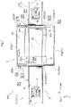
FIG. 1 is a plan view of an article transport facility. -
FIG. 2 is a perspective view of the article transport facility. -
FIG. 3 is a diagram showing the article transport facility as viewed in a width direction thereof. -
FIG. 4 is a diagram illustrating an operation performed when transporting a target article from the outside of a communication area to the inside thereof. -
FIG. 5 is a diagram illustrating an operation performed when communicating with the target article inside the communication area. -
FIG. 6 is a diagram illustrating an operation performed when transporting the target article from the inside of the communication area to the outside thereof. -
FIG. 7 is a control block diagram of the article transport facility. -
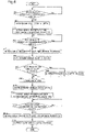
FIG. 8 is a flowchart illustrating a procedure of control performed in the article transport facility. - An embodiment of the article transport facility will be illustratively described with reference to the drawings.
- As shown in
FIGS. 1 to 3 , anarticle transport facility 100 includes atransport device 1 that transports, along a predetermined transport direction X, atarget article 9 to which anelectronic tag 9a for contactless communication is attached, and acommunication device 2 including awireless radio 20 that wirelessly communicates with theelectronic tag 9a. - The
communication device 2 is installed in acommunication area 2A that is set in a part of a transport path R along which thetarget article 9 is transported. Thetransport device 1 includes anintra-area transport unit 10 provided inside thecommunication area 2A, and anextra-area transport unit 11 provided outside thecommunication area 2A. Theintra-area transport unit 10 transports thetarget article 9 inside thecommunication area 2A, and theextra-area transport unit 11 transports thetarget article 9 outside thecommunication area 2A. In thearticle transport facility 100, while atarget article 9 is being transported by thetransport device 1 inside thecommunication area 2A, thecommunication device 2 communicates with anelectronic tag 9a attached to thetarget article 9. Note thatFIGS. 1 and2 show a state in which targetarticles 9 are being transported by theextra-area transport unit 11.FIG. 3 shows a state in which atarget article 9 is being transported by theintra-area transport unit 10, and communication is being performed between thecommunication device 2 and anelectronic tag 9a attached to thetarget article 9. - In the following, the upstream side of the transport direction X is referred to as a transport direction upstream side Xu, and the downstream side of the transport direction X is referred to as a transport direction downstream side Xd. The
target article 9 transported by thetransport device 1 moves from the transport direction upstream side Xu toward the transport direction downstream side Xd. In the following, a direction orthogonal to the transport direction X in a plan view is referred to as a width direction Y. - In the present embodiment, the
communication device 2 communicates with theelectronic tag 9a through near field communication. Specifically, thecommunication device 2 communicates with theelectronic tag 9a using an RFID (Radio Frequency Identification) system. In the present example, theelectronic tag 9a is configured as an RF tag or an IC tag, and functions as storage medium that electronically stores various types of attribute information regarding thetarget article 9, including, for example, the product name, type, price, manufacturing date, transport source, transport destination, and the like of thetarget article 9. In the present embodiment, thecommunication device 2 reads the information stored in theelectronic tag 9a through near field communication. Note that it is also possible to adopt a configuration in which thecommunication device 2 inputs (writes), deletes, or rewrites the information stored in theelectronic tag 9a. - A
target article 9 is an article that is to be transported by thetransport device 1. Examples of such an article includes a component, a raw material, a work piece, which is an article in process of production, a finished article, which is a completed product, or any of these objects housed in a container, a bag member, or the like. In the present example, atarget article 9 is an article including a product in the form of a finished article housed in a bag member as a package. In the illustrated example, eachtarget article 9 includes clothing as a product housed in a transparent packaging bag. However, thetarget article 9 is not limited to the examples described above, and may be an article including contents housed in a box-shaped container. - In the
article transport facility 100 according to the present embodiment, atarget article 9 is transported by thetransport device 1, and attribute information is read from anelectronic tag 9a attached to thetarget article 9 while thetarget article 9 is being transported. Also, thearticle transport facility 100 performs, for example, a step such as sorting a plurality oftarget articles 9 according to the attribute information read from each of the plurality oftarget articles 9. Although a detailed illustration has been omitted, thetransport device 1 transports, to a predetermined transport destination, thetarget article 9 from which the attribute information of theelectronic tag 9a has been read. Details of thearticle transport facility 100 will be described below. - As shown in
FIGS. 1 to 3 , thecommunication device 2 is installed in thecommunication area 2A that is set in a part of the transport path R. Thecommunication device 2 wirelessly communicates with theelectronic tag 9a attached to thetarget article 9, using thewireless radio 20. In the present embodiment, thewireless radio 20 is configured as a device for reading theelectronic tag 9a, and reads the attribute information from theelectronic tag 9a. Thewireless radio 20 includes an antenna (not shown), and communicates, via radio waves, with an antenna (not shown) included in theelectronic tag 9a. - In the present example, the
electronic tag 9a is configured as a passive RF tag without a battery. Also, theelectronic tag 9a generates electromotive force by receiving radio waves from the antenna of thewireless radio 20. Thus, theelectronic tag 9a emits a signal resulting from encrypting the attribute information to the antenna of thewireless radio 20. Thewireless radio 20 reads the attribute information by receiving the signal from theelectronic tag 9a. However, theelectronic tag 9a is not limited to such a configuration, and may be configured as an active RF tag including a battery. In this case, theelectronic tag 9a actively emits the signal to thewireless radio 20. - The
communication device 2 includes ashield wall 21 installed so as to surround thecommunication area 2A and having anopening 211 formed in a portion thereof corresponding to the transport path R, and ashield gate 22 that opens and closes theopening 211. - The
shield wall 21 is formed using a material that is less likely to transmit radio waves, including, for example, a metal material. In the present embodiment, theshield wall 21 includes atop wall portion 21t disposed above thecommunication area 2A, andside wall portions 21s extending downward from a peripheral edge of thetop wall portion 21t. Theside wall portions 21s are provided on both sides in the width direction Y and both sides in the transport direction X of thecommunication area 2A. In the present example, theside wall portions 21s extend from thetop wall portion 21t to a floor surface F. This can make radio waves less likely to leak between the inside and the outside of thecommunication area 2A. - In the present embodiment, the
opening 211 described above is formed in each of theside wall portions 21s provided on both sides in the transport direction X. That is, theopening 211 includes anupstream opening 211U provided on the transport direction upstream side Xu of thecommunication area 2A, and adownstream opening 211D provided on the transport direction downstream side Xd of thecommunication area 2A. Theupstream opening 211U is formed in theside wall portion 21s disposed on the transport direction upstream side Xu of thecommunication area 2A, and provides communication between the inside and the outside of thecommunication area 2A on the transport direction upstream side Xu of thecommunication area 2A. Thedownstream opening 211D is formed in theside wall portion 21s disposed on the transport direction downstream side Xd of thecommunication area 2A, and provides communication between the inside and the outside of thecommunication area 2A on the transport direction downstream side Xd of thecommunication area 2A. In the following description, in the case where theupstream opening 211U and thedownstream opening 211D do not need to be distinguished from each other, they are collectively referred to as the "opening 211". - The
shield gate 22 includes adoor member 221 that is disposed in a gap region G located between theintra-area transport unit 10 and theextra-area transport unit 11 in the transport direction X in a closed state in which theshield gate 22 shields theopening 211, and that is disposed at a position displaced from the gap region G in an open state in which theshield gate 22 opens theopening 211. - The
door member 221 is formed using a material that is less likely to transmit radio waves, including, for example, a metal material, as in the case of theshield wall 21. Thedoor member 221 is formed in a plate shape, and is disposed such that the plate thickness direction extends along the transport direction X. In the present embodiment, thedoor member 221 is configured to move along the width direction Y. More specifically, thedoor member 221 is formed by a pair of plate-shaped members disposed side by side in the width direction Y, and the pair of plate-shaped members move close to and away from each other along the width direction Y. In the present embodiment, thedoor member 221 is disposed at a position displaced from the gap region G as a result of the pair of plate-shaped members of thedoor member 221 moving away from each other along the width direction Y. This brings theshield gate 22 into the open state. Thedoor member 221 is disposed in the gap region G as a result of the pair of plate-shaped members of thedoor member 221 moving close to each other along the width direction Y. Then, theshield gate 22 is brought into the closed state as a result of the pair of plate-shaped members of thedoor member 221 abutting against each other. - In the present embodiment, the
shield gate 22 includes anupstream shield gate 22U that opens and closes theupstream opening 211U, and adownstream shield gate 22D that opens and closes thedownstream opening 211D. In the present example, theupstream shield gate 22U and thedownstream shield gate 22D have the same structure. In the following description, in the case where theupstream shield gate 22U and thedownstream shield gate 22D do not need to be distinguished from each other, they are collectively referred to as the "shield gate 22". - The
door member 221 described above includes anupstream door member 221U included in theupstream shield gate 22U, and adownstream door member 221D included in thedownstream shield gate 22D. Theupstream door member 221U is disposed in a gap region G on the transport direction upstream side Xu of thecommunication area 2A in the closed state in which theupstream opening 211U is shielded, and is disposed at a position displaced from the gap region G on the transport direction upstream side Xu of thecommunication area 2A in the open state in which theupstream opening 211U is open. Thedownstream door member 221D is disposed in a gap region G on the transport direction downstream side Xd of thecommunication area 2A in the closed state in which thedownstream opening 211D is shielded, and is disposed at a position displaced from the gap region G on the transport direction downstream side Xd of thecommunication area 2A in the open state in which thedownstream opening 211D is open. In the following description, in the case where theupstream door member 221U and thedownstream door member 221D do not need to be distinguished from each other, they are collectively referred to as the "door member 221". - The
transport device 1 includes a transport surface Ft on which thetarget article 9 is placed, and transports thetarget article 9 along the predetermined transport direction X. Thetarget articles 9 is transported by thetransport device 1 while being placed on the transport surface Ft. - As described above, the
transport device 1 includes theintra-area transport unit 10 provided inside thecommunication area 2A, and theextra-area transport unit 11 provided outside thecommunication area 2A and disposed side by side with theintra-area transport unit 10 along the transport direction X. - The
intra-area transport unit 10 includes a transport mechanism capable of transporting thetarget article 9. In the present embodiment, theintra-area transport unit 10 includes a pair ofpulleys 10b, and abelt 10a wound around the pair ofpulleys 10b, and thepulleys 10b and thebelt 10a constitute a transport mechanism. That is, in the present example, theintra-area transport unit 10 is formed by a belt conveyor. - The
extra-area transport unit 11 includes a transport mechanism capable of transporting thetarget article 9. In the present embodiment, theextra-area transport unit 11 includes anupstream transport unit 11U disposed side by side with theintra-area transport unit 10 on the transport direction upstream side Xu, and adownstream transport unit 11D disposed side by side with theintra-area transport unit 10 on the transport direction downstream side Xd. Theupstream transport unit 11U and thedownstream transport unit 11D each include a pair of pulleys (11Ub or 11Db), and a belt (11Ua or 11Da) wound around the pair of pulleys (11Ub or 11Db). That is, in the present example, both theupstream transport unit 11U and thedownstream transport unit 11D are formed by a belt conveyor. In each of theupstream transport unit 11U and thedownstream transport unit 11D, the pair of pulleys (11Ub or 11Db) and the belt (11Ua or 11Da) constitute the transport mechanism. Thus, theintra-area transport unit 10, theupstream transport unit 11U, and thedownstream transport unit 11D include their respective transport mechanisms that are capable of operating independently of each other. After being transported from theupstream transport unit 11U to theintra-area transport unit 10, thetarget article 9 is transported from theintra-area transport unit 10 to thedownstream transport unit 11D. In the following description, in the case where theupstream transport unit 11U and thedownstream transport unit 11D do not need to be distinguished from each other, they are collectively referred to as the "extra-area transport unit 11". - Here, the gap region G is formed between the
intra-area transport unit 10 and theextra-area transport unit 11 in the transport direction X, as described above. In the present example, a gap region G is formed between theintra-area transport unit 10 and theupstream transport unit 11U, and between theintra-area transport unit 10 and thedownstream transport unit 11D. When thetarget article 9 is, for example, an article having flexibility such as an object housed in a bag member or an object with an outer jacket formed of a flexible material, thetarget article 9 may fall in the gap region G while being transported. Specifically, when passing through the gap region G, thetarget article 9 may be deformed so as to be bent downward by its own weight, thus falling in the gap region G. That is, it may not be possible to stably transport the article across the gap region G at the boundary between the inside and the outside of thecommunication area 2A. However, thearticle transport facility 100 according to the present embodiment is configured to enable thetarget article 9 to be stably transported at the boundary between the inside and the outside of thecommunication area 2A even when thetarget article 9 is an article having flexibility as described above. This will be described in detail below. - In the
article transport facility 100, at least one of theintra-area transport unit 10 and theextra-area transport unit 11 is configured to be movable along the transport direction X. This allows theintra-area transport unit 10 and theextra-area transport unit 11 to move close to each other in the transport direction X, thus making it possible to temporarily reduce the size of the gap region G. In the present embodiment, theintra-area transport unit 10 is configured to be movable to both the transport direction upstream side Xu and the transport direction downstream side Xd along the transport direction X. This makes it possible to reduce the size of the gap region G on each of the transport direction upstream side Xu and the transport direction downstream side Xd of thecommunication area 2A as needed. - As shown in
FIG. 3 , in the present embodiment, theintra-area transport unit 10 includes amovable support portion 10c that supports a transport mechanism (thebelt 10a and the pair ofpulleys 10b in the present example) and that moves along the transport direction X, and aguide portion 10d that guides themovable support portion 10c along the transport direction X. In the illustrated example, theguide portion 10d is formed by a pair of rails extending along the transport direction X (see alsoFIG. 1 ). - In the present embodiment, the position of the
extra-area transport unit 11 in the transport direction X is fixed. More specifically, the position of each of theupstream transport unit 11U and thedownstream transport unit 11D in the transport direction X is fixed. As shown inFIG. 3 , theupstream transport unit 11U includes an upstream fixed support part 11Uc that supports a transport mechanism (the belt 11Ua and the pair of pulleys 11Ub in the present example) and that is fixed to the floor surface F. Thedownstream transport unit 11D includes a downstream fixed support part 11Dc that supports a transport mechanism (the belt 11Da and the pair of pulleys 11Ub in the present example) and that is fixed to the floor surface F. In the illustrated example, the upstream fixed support part 11Uc and the downstream fixed support part 11Dc are each formed by a strut, for example. - As described above, in the present embodiment, the
intra-area transport unit 10 is movable to both the transport direction upstream side Xu and the transport direction downstream side Xd. In the present example, theintra-area transport unit 10 is configured so as to be able to change its position to a reference position Ps, an upstream transport position Pu located on the transport direction upstream side Xu relative to the reference position Ps, and a downstream transport position Pd located on the transport direction downstream side Xd relative to the reference position Ps, by moving along the transport direction X. - The
transport device 1 transports thetarget article 9 between theintra-area transport unit 10 and theextra-area transport unit 11, with theintra-area transport unit 10 located at the upstream transport position Pu or the downstream transport position Pd. In the following, a transport period Tt is a period during which atarget article 9 is transported between theintra-area transport unit 10 and theextra-area transport unit 11, and a non-transport period Tn is a period during which thetarget article 9 is not transported between theintra-area transport unit 10 and theextra-area transport unit 11. A transport period Tt and a non-transport period Tn are concepts that can occur at the same time at locations that are different from each other. For example, during a transport period Tt during which thetarget article 9 is transported between theintra-area transport unit 10 and theupstream transport unit 11U, theintra-area transport unit 10 and thedownstream transport unit 11D are in a non-transport period Tn during which thetarget article 9 is not transported therebetween. - Here, it is assumed that a second interval L2 is the length of a gap region G that enables the
door member 221 to be disposed between theintra-area transport unit 10 and theextra-area transport unit 11. Also, a first interval L1 is a length of a gap region G that is shorter than the second interval L2, and that enables thetarget article 9 to be appropriately transported between theintra-area transport unit 10 and theextra-area transport unit 11. In the present example, the first interval L1 is an interval shorter than the thickness (the length in the transport direction X) of thedoor member 221. Preferably, the first interval L1 is a minimum interval without any interference between the transport mechanism of theintra-area transport unit 10 and the transport mechanism of theextra-area transport unit 11, for example. - As shown in
FIGS. 1 to 3 and5 , in the present embodiment, the length of the gap region G between theintra-area transport unit 10 and theextra-area transport unit 11 is set to the second interval L2 in a state in which theintra-area transport unit 10 is located at the reference position Ps. In the present example, in a state in which theintra-area transport unit 10 is located at the reference position Ps, the length of the gap region G is set to the second interval L2 both between theintra-area transport unit 10 and theupstream transport unit 11U, and between theintra-area transport unit 10 and thedownstream transport unit 11D. - As shown in
FIG. 4 , the length of the gap region G between theintra-area transport unit 10 and theupstream transport unit 11U is set to the first interval L1 in a state in which theintra-area transport unit 10 is located at the upstream transport position Pu. In this state, the length of the gap region G between theintra-area transport unit 10 and thedownstream transport unit 11D is set to be greater than or equal to the second interval L2. Here, the length is a third interval L3 that is longer than the second interval L2. - On the other hand, as shown in
FIG. 6 , the length of the gap region G between theintra-area transport unit 10 and thedownstream transport unit 11D is set to the first interval L1 in a state in which theintra-area transport unit 10 is located at the downstream transport position Pd. In this state, the length of the gap region G between theintra-area transport unit 10 and theupstream transport unit 11U is set to be greater than or equal to the second interval L2. Here, the length is set to the third interval L3 that is longer than the second interval L2. - As shown in
FIGS. 4 to 6 , during at least a part of the non-transport period Tn, the length in the transport direction X of the gap region G is set to be greater than or equal to the second interval L2, and theshield gate 22 is in the closed state. During the transport period Tt, theshield gate 22 is in the open state, and the length in the transport direction X of the gap region G is set to the first interval L1 that is shorter than the second interval L2. This enables thetarget article 9 to be transported between theintra-area transport unit 10 and theextra-area transport unit 11 across the gap region G even when thetarget article 9 is an article having flexibility. Thus, it is possible to stably transport thetarget article 9 at a boundary between the inside and the outside of thecommunication area 2A. Furthermore, during at least a part of the non-transport period Tn, the length in the transport direction X of the gap region G is set to be greater than or equal to the second interval L2, and theshield gate 22 is in the closed state. Accordingly, it is possible to ensure a period during which radio waves are less likely to leak between the inside and the outside of thecommunication area 2A, thus making it possible to favorably perform communication between thecommunication device 2 and theelectronic tag 9a inside thecommunication area 2A within the ensured period. - In the state shown in
FIG. 4 , the transport period Tt occurs between theintra-area transport unit 10 and theupstream transport unit 11U, so that theupstream shield gate 22U is in the open state, and the length of the gap region G is set to the first interval L1. The non-transport period Tn occurs between theintra-area transport unit 10 and thedownstream transport unit 11D, so that the length of the gap region G is set to the third interval L3, and thedownstream shield gate 22D is in the closed state. That is, in the present example, when theupstream shield gate 22U is in the open state, thedownstream shield gate 22D is in the closed state, and the length of the gap region G corresponding to theupstream shield gate 22U is set to the first interval L1. This makes it possible to stably transport thetarget article 9 between theintra-area transport unit 10 and theupstream transport unit 11U. - Next, as shown in
FIG. 5 , in the present embodiment, thecommunication device 2 wirelessly communicates with theelectronic tag 9a, while both theupstream shield gate 22U and thedownstream shield gate 22D are in the closed state. In the example shown inFIG. 5 , the non-transport period Tn occurs both between theintra-area transport unit 10 and theupstream transport unit 11U, and between theintra-area transport unit 10 and thedownstream transport unit 11D, so that the gap regions G are set to the second interval L2, and theupstream shield gate 22U and thedownstream shield gate 22D are in the closed state. This can make radio waves less likely to leak between the inside and the outside of thecommunication area 2A, thus making it possible to favorably perform communication between thecommunication device 2 and theelectronic tag 9a inside thecommunication area 2A. - Thereafter, the state shown in
FIG. 6 is brought about. In this state, the transport period Tt occurs between theintra-area transport unit 10 and thedownstream transport unit 11D, so that thedownstream shield gate 22D is in the open state, and the length of the gap region G is set to the first interval L1. The non-transport period Tn occurs between theintra-area transport unit 10 and theupstream transport unit 11U, so that the length of the gap region G is set to the third interval L3, and theupstream shield gate 22U is in the closed state. That is, in the present example, when theupstream shield gate 22U is in the closed state, thedownstream shield gate 22D is in the open state, and the length of the gap region G corresponding to thedownstream shield gate 22D is set to the first interval L1. This makes it possible to stably transport thetarget article 9 between theintra-area transport unit 10 and thedownstream transport unit 11D. - Next, a control configuration of the
article transport facility 100 will be described. As shown inFIG. 7 , thearticle transport facility 100 includes acontrol device 3. Thecontrol device 3 includes, for example, a processor such as a microcomputer, and a peripheral circuit such as a memory. Various functions are implemented by these pieces of hardware working cooperatively with a program executed on a processor such as a computer. - The
control device 3 is configured to be capable of wired or wireless communication with each of thetransport device 1 and thecommunication device 2. In the present embodiment, thearticle transport facility 100 includes a sensor Se that detects the operation states of the facility. Also, thecontrol device 3 is configured to be capable of obtaining information detected by the sensor Se. - In the present embodiment, the
control device 3 separately controls theintra-area transport unit 10, theupstream transport unit 11U, and thedownstream transport unit 11D. Each of theintra-area transport unit 10, theupstream transport unit 11U, and thedownstream transport unit 11D includes its own control unit (not shown), and fine control of each of the transport units is performed by the control unit of its own. - In the present embodiment, the
intra-area transport unit 10 includes an intra-area transport driving part 10mt that drives a transport mechanism (thebelt 10a and the pair ofpulleys 10b in the present example) for transporting thetarget article 9 along the transport direction X, and a slide driving part 10ms that slidingly moves the transport mechanism along the transport direction X. Theupstream transport unit 11U includes an upstream transport driving part 11Um that drives a transport mechanism (the belt 11Ua and the pair of pulleys 11Ub in the present example) for transporting thetarget article 9 along the transport direction X. Thedownstream transport unit 11D includes a downstream transport driving part 11Dm that drives a transport mechanism (the belt 11Da and the pair of pulleys 11Db in the present example) for transporting thetarget article 9 along the transport direction X. These driving parts are each formed by a motor, for example. - In the present embodiment, the
control device 3 separately controls theupstream shield gate 22U and thedownstream shield gate 22D. Each of theupstream shield gate 22U and thedownstream shield gate 22D includes its own control unit (not shown), and fine control of each of the gates is performed by the control unit of its own. In the present example, theupstream shield gate 22U includes an upstream gate driving part 22Um that drives theupstream door member 221U. Thedownstream shield gate 22D includes a downstream gate driving part 22Dm that drives thedownstream door member 221D. - In the present embodiment, the sensor Se includes an upstream position sensor Se1 that detects the position of the
target article 9 on the transport direction upstream side Xu relative to thecommunication area 2A, a downstream position sensor Se2 that detects the position of thetarget article 9 on the transport direction downstream side Xd relative to thecommunication area 2A, an upstream gate sensor Se3 that detects the open/closed state of theupstream shield gate 22U, a downstream gate sensor Se4 that detects the open/closed state of thedownstream shield gate 22D, an upstream gate passage sensor Se5, and a downstream gate passage sensor Se6. - As shown in
FIGS. 1 to 3 , the upstream position sensor Se1 is provided so as to correspond to theupstream transport unit 11U, and detects that thetarget article 9 transported by theupstream transport unit 11U has reached a predetermined position. The downstream position sensor Se2 is provided so as to correspond to thedownstream transport unit 11D, and detects that thetarget article 9 transported by thedownstream transport unit 11D has reached a predetermined position. The upstream position sensor Se1 and the downstream position sensor Se2 are each formed, for example, by a photosensor that emits light and that detects thetarget article 9 as a result of the emitted light being blocked. However, the upstream position sensor Se1 and the downstream position sensor Se2 are not limited to such a configuration, and may be formed using, for example, a limit switch or any other known means capable of detecting thetarget article 9 transported on the transport surface Ft. - As shown in
FIG. 3 , the upstream gate sensor Se3 is provided so as to correspond to theupstream shield gate 22U, and detects theupstream door member 221U. In the present example, the upstream gate sensor Se3 separately detects that theupstream door member 221U is located at a position corresponding to the open state, and that theupstream door member 221U is located at a position corresponding to the closed state. The downstream gate sensor Se4 is provided so as to correspond to thedownstream shield gate 22D, and detects thedownstream door member 221D. In the present example, the downstream gate sensor Se4 separately detects that thedownstream door member 221D is located at a position corresponding to the open state, and that thedownstream door member 221D is located at a position corresponding to the closed state. The upstream gate sensor Se3 and the downstream gate sensor Se4 are each formed, for example, by a photosensor that emits light and that detects thedoor member 221 and thetarget article 9 as a result of the emitted light being blocked. However, the upstream gate sensor Se3 and the downstream gate sensor Se4 are not limited to such a configuration, and may be formed using, for example, a limit switch or any other known means capable of detecting thedoor member 221 moving along theopening 211, and thetarget article 9 passing through theopening 211. - The upstream gate passage sensor Se5 is provided so as to correspond to the
upstream opening 211U, and detects that thetarget article 9 has passed through theupstream opening 211U. The downstream gate passage sensor Se6 is provided so as to correspond to thedownstream opening 211D, and detects that thetarget article 9 has passed through thedownstream opening 211D. The upstream gate passage sensor Se5 and the downstream gate passage sensor Se6 are each formed, for example, by a photosensor that emits light and that detects the passage of thetarget article 9 as a result of the emitted light having been blocked being later no longer blocked. However, the upstream gate passage sensor Se5 and the downstream gate passage sensor Se6 are not limited to such a configuration, and may be formed using, for example, a limit switch or any other known means capable of detecting thetarget article 9 transported on the transport surface Ft. - In the present embodiment, when the
target article 9 is detected by the upstream position sensor Se1, thecontrol device 3 brings theupstream shield gate 22U into the open state, and causes theintra-area transport unit 10 to move to the upstream transport position Pu (seeFIG. 4 ). This brings about a state in which thetarget article 9 can be transported between theupstream transport unit 11U and theintra-area transport unit 10. - In the present embodiment, when the upstream gate sensor Se3 detects that the
target article 9 has passed through theupstream opening 211U, thecontrol device 3 causes theintra-area transport unit 10 to move to the reference position Ps, and brings theupstream shield gate 22U into the closed state (seeFIG. 5 ). On the conditions that the upstream gate sensor Se3 detects that theupstream shield gate 22U is in the closed state, and that the downstream gate sensor Se4 detects that thedownstream shield gate 22D is in the closed state, thecontrol device 3 causes thecommunication device 2 to communicate with theelectronic tag 9a, and reads the attribute information from theelectronic tag 9a. This enables favorable communication between thecommunication device 2 and theelectronic tag 9a, with the inside and the outside of thecommunication area 2A shielded from each other. - In the present embodiment, after communication has been performed between the
communication device 2 and theelectronic tag 9a, thecontrol device 3 brings thedownstream shield gate 22D into the open state, and causes theintra-area transport unit 10 to move to the downstream transport position Pd (seeFIG. 6 ). This brings about a state in which thetarget article 9 can be transported between theintra-area transport unit 10 and thedownstream transport unit 11D. - In the following, a procedure of control performed by the
article transport facility 100 will be described with reference toFIG. 8 . - In the
article transport facility 100, first, whether or not thetarget article 9 has reached theupstream transport unit 11U is determined (step #1). This determination is made based on a result of detection performed by the upstream position sensor Se1. If it is determined that thetarget article 9 has not reached theupstream transport unit 11U (step #1: No),step # 1 is repeatedly executed. If it is determined that thetarget article 9 has reached theupstream transport unit 11U (step #1: Yes), theupstream shield gate 22U is brought into the open state (step #2), and theintra-area transport unit 10 is caused to be located at the upstream transport position Pu (step #3). - Thereafter, whether or not the
target article 9 has reached inside thecommunication area 2A through theupstream opening 211U is determined (step #4). This determination is made based on a result of detection performed by the upstream gate passage sensor Se5. If it is determined that thetarget article 9 has not reached inside thecommunication area 2A (step #4: No),step # 4 is repeatedly executed. If it is determined that thetarget article 9 has reached inside thecommunication area 2A (step #4: Yes), theintra-area transport unit 10 is moved to the reference position Ps (step #5), and theupstream shield gate 22U is brought into the closed state (step #6). Next, whether or not thedownstream shield gate 22D, which is theshield gate 22 on the other side, is in the closed state (step #7). If it is determined that thedownstream shield gate 22D is not in the closed state, or in other words, if it is determined that thedownstream shield gate 22D is in the open state (step #7: No), thedownstream shield gate 22D is brought into the closed state (step #8). - If it is determined that both the
upstream shield gate 22U and thedownstream shield gate 22D are in the closed state, communication with theelectronic tag 9a attached to thetarget article 9 is performed using the communication device 2 (step #9). By doing so, the attribute information is read from theelectronic tag 9a. After completion of the communication, thedownstream shield gate 22D is brought into the open state (step #10), and theintra-area transport unit 10 is caused to be located at the downstream transport position Pd (step #11). - Thereafter, whether or not the
target article 9 has reached thedownstream transport unit 11D through thedownstream opening 211D is determined (step #12). This determination is made based on a result of detection performed by at least one of the downstream gate passage sensor Se6 and the downstream position sensor Se2. If it is determined that thetarget article 9 has not reached thedownstream transport unit 11D (step #12: No),step # 12 is repeatedly executed. If it is determined that thetarget article 9 has reached thedownstream transport unit 11D (step #12: Yes), theintra-area transport unit 10 is caused to be located at the reference position Ps (step #13), and thedownstream shield gate 22D is brought into the closed state (step #14). - Next, other embodiments of the article transport facility will be described.
- (1) The above embodiment describes an example in which the
intra-area transport unit 10 is configured to be movable along the transport direction X, and the position of theextra-area transport unit 11 in the transport direction X is fixed. However, the present disclosure is not limited to such an example. Alternatively or additionally to theintra-area transport unit 10, theextra-area transport unit 11 may be configured to be movable along the transport direction X. For example, in the case where the position of theintra-area transport unit 10 in the transport direction X is fixed, and theextra-area transport unit 11 is configured to be movable along the transport direction X, during the transport period Tt, theshield gate 22 is in the open state, and theextra-area transport unit 11 moves in a direction toward theintra-area transport unit 10, so that the length in the transport direction X of the gap region G between theextra-area transport unit 11 and theintra-area transport unit 10 is set to the first interval L1 that is shorter than the second interval L2. For example, in the case where both theintra-area transport unit 10 and theextra-area transport unit 11 are configured to be movable along the transport direction X, during the transport period Tt, theshield gate 22 is in the open state, and both theextra-area transport unit 11 and theintra-area transport unit 10 move in a direction toward each other, so that the length in the transport direction X of the gap region G between theextra-area transport unit 11 and theintra-area transport unit 10 is set to the first interval L1 that is shorter than the second interval L2. - (2) The above embodiment describes an example in which both the
intra-area transport unit 10 and theextra-area transport unit 11 are formed by a belt conveyor. However, the present disclosure is not limited to such an example. These transport units may be formed by other known transporting means. For example, at least one of theintra-area transport unit 10 and theextra-area transport unit 11 may be formed by a roller conveyor. - (3) The above embodiment describes an example in which the
door member 221 is configured to move along the width direction Y. However, the present disclosure is not limited to such an example. Thedoor member 221 may be configured to move along a direction different from the width direction Y, for example, the up-down direction, or may be configured to swing using a hinge. The above embodiment describes an example in which thedoor member 221 is formed by a pair of plate-shaped members disposed side by side in the width direction Y. However, the present disclosure is not limited to such an example. Thedoor member 221 may be formed by one plate-shaped member, for example. - (4) The above embodiment describes an example in which the
upstream shield gate 22U and thedownstream shield gate 22D have the same configuration. However, the present disclosure is not limited to such an example. Theupstream shield gate 22U and thedownstream shield gate 22D may have structures different from each other. For example, one of theupstream shield gate 22U and thedownstream shield gate 22D may include adoor member 221 that moves along the width direction Y, and the other may include adoor member 221 that moves along the up-down direction. - (5) Note that the configurations disclosed in the embodiments described above are applicable in combination with configurations disclosed in other embodiments as long as no inconsistency arises. With regard to the other configurations as well, the embodiments disclosed herein are illustrative in all respects. Therefore, various modifications and alterations may be made as appropriate without departing from the gist of the present disclosure.
- An outline of the article transport facility described above will be described below.
- An article transport facility includes:
- a transport device that transports a target article to which an electronic tag for contactless communication is attached, that includes a transport surface on which the target article is to be placed, and that transports the target article along a predetermined transport direction; and
- a communication device installed in a communication area that is set in a part of a transport path along which the target article is transported, and including a wireless radio that wirelessly communicates with the electronic tag,
- wherein the transport device includes an intra-area transport unit provided inside the communication area, and an extra-area transport unit provided outside the communication area and disposed side by side with the intra-area transport unit along the transport direction,
- the communication device includes a shield wall installed so as to surround the communication area, and having an opening formed in a portion thereof corresponding to the transport path, and a shield gate that opens and closes the opening,
- the shield gate includes a door member that is disposed in a gap region located between the intra-area transport unit and the extra-area transport unit in the transport direction in a closed state in which the shield gate shields the opening, and is disposed at a position displaced from the gap region in an open state in which the shield gate opens the opening,
- at least one of the intra-area transport unit and the extra-area transport unit is configured to be movable along the transport direction,
- assuming that a second interval is a length of the gap region that allows the door member to be disposed between the intra-area transport unit and the extra-area transport unit, a transport period is a period during which the target article is transported between the intra-area transport unit and the extra-area transport unit, and a non-transport period is a period during which the target article is not transported between the intra-area transport unit and the extra-area transport unit,
- during at least a part of the non-transport period, a length in the transport direction of the gap region is set to be greater than or equal to the second interval, and the shield gate is in the closed state, and,
- during the transport period, the shield gate is in the open state, and a length in the transport direction of the gap region is set to a first interval that is shorter than the second interval.
- With this configuration, during the transport period during which the target article is transported between the intra-area transport unit and the extra-area transport unit, the length in the transport direction of the gap region located between the intra-area transport unit and the extra-area transport unit is set to the first interval that is shorter than the second interval that allows the door member to be disposed between the intra-area transport unit and the extra-area transport unit. Accordingly, even in the case where the target article is an article having flexibility, or where the second interval is long relative to the size of the article, it is possible to stably transport the target article between the intra-area transport unit and the extra-area transport unit across the gap region having the first interval shorter than the second interval. Thus, it is possible to stably transport the article at the boundary between the inside and the outside of the communication area. With this configuration, during at least a part of the non-transport period, the length in the transport direction of the gap region is set to be greater than or equal to the second interval, and the shield gate is in the closed state. Accordingly, it is possible to ensure a period during which radio waves are less likely to leak between the inside and the outside of the communication area, thus making it possible to favorably perform communication between the communication device and the electronic tag inside the communication area within the ensured period.
- Here, it is preferable that
- the extra-area transport unit includes an upstream transport unit disposed side by side with the intra-area transport unit on an upstream side of the transport direction, and a downstream transport unit disposed side by side with the intra-area transport unit on a downstream side of the transport direction,
- the opening incudes an upstream opening provided upstream of the communication area, and a downstream opening provided downstream of the communication area,
- the shield gate includes an upstream shield gate that opens and closes the upstream opening, and a downstream shield gate that opens and closes the downstream opening, and
- the intra-area transport unit is configured to be movable to both upstream and downstream sides along the transport direction, and positions in the transport direction of the upstream transport unit and the downstream transport unit are fixed.
- With this configuration, only the intra-area transport unit, out of the upstream transport unit, the downstream transport unit, and the intra-area transport unit, is configured to be movable along the transport direction, whereby each of the gap region between the intra-area transport unit and the upstream transport unit, and the gap region between the intra-area transport unit and the downstream transport unit can be changed to the first interval as needed. Thus, with this configuration, it is possible to reduce the number of transport units that are to be configured to be movable. Accordingly, an article transport facility capable of stably transporting the target article in the gap regions on both the upstream and downstream sides of the transport direction relative to the communication area can be realized with a relatively simple configuration.
- It is preferable that,
- when the upstream shield gate is in the open state, the downstream shield gate is in the closed state, and a length of the gap region corresponding to the upstream shield gate is set to the first interval, and,
- when the downstream shield gate is in the open state, the upstream shield gate is in the closed state, and a length of the gap region corresponding to the downstream shield gate is set to the first interval.
- With this configuration, when the upstream shield gate is in the open state, the length of the gap region corresponding to the upstream shield gate is set to the first interval. Thus, the target article can be appropriately transported (loaded) to the inside of the communication area from the outside thereof. Also, in the above-described case, the downstream shield gate is in the closed state, whereby preparation for wireless communication with the electronic tag attached to the target article can be performed promptly. Accordingly, the cycle time can be easily improved. With this configuration, when the downstream shield gate is in the open state, the upstream shield gate is in the closed state, and the length of the gap region corresponding to the downstream shield gate is set to the first interval. Thus, on the downstream side in the transport direction of the communication area, the target article can be appropriately transported (unloaded) to the outside of the communication area from the inside thereof. On the upstream side in the transport direction of the communication area, the possibility that the subsequently transported target article will fall in the gap region can be reduced since the upstream shield gate is in the closed state despite that the length of the gap region is at least the second interval or longer, i.e., wider.
- It is preferable that
the communication device wirelessly communicates with the electronic tag while both the upstream shield gate and the downstream shield gate are in the closed state. - With this configuration, leakage of radio waves between the inside and the outside of the communication area can be effectively suppressed, thus making it possible to favorably perform communication between the communication device and the electronic tag inside the communication area.
- The technique according to the present disclosure is applicable to an article transport facility.
-
- 100: Article transport facility
- 1: Transport device
- 10: Intra-area transport unit
- 11: Extra-area transport unit
- 11D: Downstream transport unit
- 11U: Upstream transport unit
- 2: Communication device
- 2A: Communication area
- 20: Wireless radio
- 21: Shield wall
- 22: Shield gate
- 22D: Downstream shield gate
- 22U: Upstream shield gate
- 211: Opening
- 211D: Downstream opening
- 211U: Upstream opening
- 221: Door member
- 221D: Downstream door member
- 221U: Upstream door member
- 9: Target article
- 9a: Electronic tag
- Ft: Transport surface
- G: Gap region
- L1: First interval
- L2: Second interval
- R: Transport path
- Tn: Non-transport period
- Tt: Transport period
- X: Transport direction
- Xd: Transport direction downstream side
- Xu: Transport direction upstream side
- Y: Width direction
Claims (4)
- An article transport facility comprising:a transport device that transports a target article to which an electronic tag for contactless communication is attached, that has a transport surface on which the target article is placeable, and that transports the target article in a predetermined transport direction; anda communication device that is installed in a communication area set at a part of a transport path along which the target article is transported and that includes a wireless radio that wirelessly communicates with the electronic tag,wherein the transport device includes an intra-area transport unit provided inside the communication area and an extra-area transport unit provided outside the communication area and disposed next to the intra-area transport unit in the transport direction,the communication device includes:a shield wall surrounding the communication area and having at least one opening at a portion thereof corresponding to the transport path; andat least one shield gate that exposes and shields the at least one opening,the at least one shield gate includes a door member configured to be (i) in a gap region between the intra-area transport unit and the extra-area transport unit in the transport direction in a closed state in which the at least one shield gate shields the at least one opening and (ii) outside the gap region in an open state in which the at least one shield gate opens the at least one opening,at least either the intra-area transport unit or the extra-area transport unit is movable in the transport direction,with (i) a second interval being a length of the gap region that allows the door member to be between the intra-area transport unit and the extra-area transport unit, (ii) a transport period being a period during which the target article is transported between the intra-area transport unit and the extra-area transport unit, and (iii) a non-transport period being a period during which the target article is not transported between the intra-area transport unit and the extra-area transport unit,during at least a part of the non-transport period, the gap region has in the transport direction a length greater than or equal to the second interval, and the at least one shield gate is in the closed state, and,during the transport period, the at least one shield gate is in the open state, and the gap region has in the transport direction a length of a first interval shorter than the second interval.
- The article transport facility according to claim 1,wherein the extra-area transport unit includes:an upstream transport unit disposed next to the intra-area transport unit on an upstream side of the transport direction; anda downstream transport unit disposed next to the intra-area transport unit on a downstream side of the transport direction,the at least one opening includes:an upstream opening provided upstream of the communication area; anda downstream opening provided downstream of the communication area,the at least one shield gate includes:an upstream shield gate that exposes and shields the upstream opening; anda downstream shield gate that exposes and shields the downstream opening, andthe intra-area transport unit is movable to both upstream and downstream sides in the transport direction, and the upstream transport unit and the downstream transport unit are fixed in position in the transport direction.
- The article transport facility according to claim 2,wherein, when the upstream shield gate is in the open state, the downstream shield gate is in the closed state, and the gap region corresponding to the upstream shield gate has a length of the first interval, and,when the downstream shield gate is in the open state, the upstream shield gate is in the closed state, and the gap region corresponding to the downstream shield gate has a length of the first interval.
- The article transport facility according to claim 2 or 3,
wherein the communication device wirelessly communicates with the electronic tag while both the upstream shield gate and the downstream shield gate are in the closed state.
Applications Claiming Priority (2)
| Application Number | Priority Date | Filing Date | Title |
|---|---|---|---|
| JP2019159677A JP7192718B2 (en) | 2019-09-02 | 2019-09-02 | Goods transport equipment |
| PCT/JP2020/020065 WO2021044674A1 (en) | 2019-09-02 | 2020-05-21 | Article transport facility |
Publications (4)
| Publication Number | Publication Date |
|---|---|
| EP4015416A1 true EP4015416A1 (en) | 2022-06-22 |
| EP4015416A4 EP4015416A4 (en) | 2023-08-23 |
| EP4015416C0 EP4015416C0 (en) | 2025-12-03 |
| EP4015416B1 EP4015416B1 (en) | 2025-12-03 |
Family
ID=74848947
Family Applications (1)
| Application Number | Title | Priority Date | Filing Date |
|---|---|---|---|
| EP20860794.5A Active EP4015416B1 (en) | 2019-09-02 | 2020-05-21 | Article transport facility |
Country Status (7)
| Country | Link |
|---|---|
| US (1) | US12006158B2 (en) |
| EP (1) | EP4015416B1 (en) |
| JP (1) | JP7192718B2 (en) |
| KR (1) | KR102838839B1 (en) |
| CN (1) | CN114341027B (en) |
| AU (1) | AU2020343539B2 (en) |
| WO (1) | WO2021044674A1 (en) |
Families Citing this family (5)
| Publication number | Priority date | Publication date | Assignee | Title |
|---|---|---|---|---|
| WO2021229133A1 (en) * | 2020-05-15 | 2021-11-18 | Rielec Automatización Industrial SL | High-speed tunnel for the reading and mass encoding of rfid labels contained in a package |
| JP7602011B2 (en) | 2021-03-10 | 2024-12-17 | パイオニア株式会社 | Sensor Device |
| JP7734974B2 (en) * | 2021-05-07 | 2025-09-08 | 株式会社ハイテム | Combination structure of belt conveyor and shutter device |
| JP2024136097A (en) * | 2023-03-23 | 2024-10-04 | 株式会社ダイフク | Goods handling equipment |
| CN116441123A (en) * | 2023-04-28 | 2023-07-18 | 深圳市两岸半导体科技有限公司 | Dispensing and drying integrated equipment |
Family Cites Families (21)
| Publication number | Priority date | Publication date | Assignee | Title |
|---|---|---|---|---|
| DE2647243A1 (en) * | 1976-10-20 | 1978-04-27 | Mt Verriegelungstechnik Vorric | Fire localising gear on conveying plant - removes conveyor section from area controlled by fire door to allow closure of door |
| JPS56122821A (en) * | 1980-03-04 | 1981-09-26 | Sanyurejin Kk | Urethane resin composition |
| CA1201836A (en) * | 1982-02-22 | 1986-03-11 | James S. Dix | Arylene sulfide compositions containing calcium sulfate |
| JPS604085B2 (en) * | 1983-08-20 | 1985-02-01 | 日東精工株式会社 | Goods transfer device |
| JPH0229561B2 (en) * | 1984-09-03 | 1990-06-29 | Niigata Tetsukosho Kk | NYUSHUTSUKOSOCHI |
| JPH0745287B2 (en) * | 1987-07-09 | 1995-05-17 | 株式会社熊平製作所 | Conveying device that conveys conveyed goods inside and outside the partition |
| JPH10147413A (en) * | 1996-11-18 | 1998-06-02 | Nittetsu Semiconductor Kk | Conveyor device |
| JP3610868B2 (en) | 2000-03-10 | 2005-01-19 | 株式会社ダイフク | Method for controlling plate-shaped body transfer / conveying apparatus |
| CN101014517A (en) * | 2004-09-07 | 2007-08-08 | 松下电器产业株式会社 | Commodity incoming/outgoing management system |
| AU2005225102B2 (en) * | 2004-11-01 | 2010-07-08 | Tna Australia Pty Limited | A slip conveyor assembly |
| CN101648454B (en) * | 2008-08-13 | 2011-05-11 | 东远精技工业股份有限公司 | Cassette device for automatic screen printing production line |
| CN101428708B (en) * | 2008-12-15 | 2012-08-22 | 友达光电股份有限公司 | Substrate transfer device and method |
| CN102502223B (en) * | 2011-09-30 | 2013-12-11 | 广东宏威陶瓷实业有限公司 | Position correction device |
| DE102014103900A1 (en) * | 2014-03-21 | 2015-09-24 | Krones Ag | Transport device and transport method for container treatment plant |
| CN105501526B (en) * | 2015-12-30 | 2017-12-29 | 苏州澳昆智能机器人技术有限公司 | Two generation aseptic bag milk bag gift box boxing systems |
| JP6423499B1 (en) | 2017-05-18 | 2018-11-14 | トーヨーカネツソリューションズ株式会社 | Transport system and control method thereof |
| JP7018718B2 (en) | 2017-07-18 | 2022-02-14 | 東芝テック株式会社 | Wireless tag reader |
| US20200307919A1 (en) * | 2019-03-29 | 2020-10-01 | Transnorm System Gmbh | Item conveying apparatus for a material handling environment |
| JP7192711B2 (en) * | 2019-08-20 | 2022-12-20 | 株式会社ダイフク | Conveyor |
| JP7537216B2 (en) * | 2020-09-30 | 2024-08-21 | 富士フイルムビジネスイノベーション株式会社 | Information processing device and program |
| JP2022064601A (en) * | 2020-10-14 | 2022-04-26 | 京セラドキュメントソリューションズ株式会社 | Image forming device |
-
2019
- 2019-09-02 JP JP2019159677A patent/JP7192718B2/en active Active
-
2020
- 2020-05-21 KR KR1020227009657A patent/KR102838839B1/en active Active
- 2020-05-21 EP EP20860794.5A patent/EP4015416B1/en active Active
- 2020-05-21 CN CN202080061561.6A patent/CN114341027B/en active Active
- 2020-05-21 AU AU2020343539A patent/AU2020343539B2/en active Active
- 2020-05-21 US US17/639,491 patent/US12006158B2/en active Active
- 2020-05-21 WO PCT/JP2020/020065 patent/WO2021044674A1/en not_active Ceased
Also Published As
| Publication number | Publication date |
|---|---|
| KR20220051375A (en) | 2022-04-26 |
| CN114341027A (en) | 2022-04-12 |
| EP4015416C0 (en) | 2025-12-03 |
| AU2020343539B2 (en) | 2025-10-02 |
| CN114341027B (en) | 2024-05-14 |
| EP4015416B1 (en) | 2025-12-03 |
| US12006158B2 (en) | 2024-06-11 |
| AU2020343539A1 (en) | 2022-04-21 |
| WO2021044674A1 (en) | 2021-03-11 |
| US20220324656A1 (en) | 2022-10-13 |
| KR102838839B1 (en) | 2025-07-24 |
| JP7192718B2 (en) | 2022-12-20 |
| EP4015416A4 (en) | 2023-08-23 |
| JP2021038050A (en) | 2021-03-11 |
Similar Documents
| Publication | Publication Date | Title |
|---|---|---|
| EP4015416B1 (en) | Article transport facility | |
| JP5263263B2 (en) | RFID system | |
| EP3432193A1 (en) | Wireless tag reading apparatus | |
| JP7221700B2 (en) | RFID reading system | |
| CN102456143B (en) | RFID Full Container Load scanning means | |
| KR101452909B1 (en) | Apparatus for checking radio frequency identification tag | |
| US20210073487A1 (en) | Tag reading system | |
| US20080094179A1 (en) | Identification device for objects with a transponder and a corresponding method | |
| KR101200343B1 (en) | Shipment verification equipment for medical supplies | |
| JP2017538641A (en) | Radio frequency identification arrangement for a chain conveyor for goods and chain conveyor having said radio frequency identification arrangement | |
| CN101778784A (en) | Inspection system | |
| KR102311217B1 (en) | Product inspection equipment for rfid tags | |
| EP3432192A1 (en) | Wireless tag reading apparatus | |
| KR20100026180A (en) | Rfid reader antenna structure for increasing identifying rfid tag | |
| JP2019067328A (en) | Register system using RF tag | |
| JP6647646B1 (en) | Electronic tag reader | |
| KR101360898B1 (en) | Verification equipment of shipment and verification method thereof | |
| JP7328841B2 (en) | RFID tag reader | |
| JP2020071129A (en) | Inspection system | |
| JP7160626B2 (en) | Radio tag reader and program | |
| JP5360866B2 (en) | IC tag batch reading gate and electric field leakage prevention method | |
| KR101044514B1 (en) | RFID Tag Recognition Automation Device | |
| TWI650730B (en) | Carrier pallet mobile identification system | |
| JP2020064562A (en) | Wireless tag reading device | |
| JP2022035399A (en) | Readers and systems |
Legal Events
| Date | Code | Title | Description |
|---|---|---|---|
| STAA | Information on the status of an ep patent application or granted ep patent |
Free format text: STATUS: THE INTERNATIONAL PUBLICATION HAS BEEN MADE |
|
| PUAI | Public reference made under article 153(3) epc to a published international application that has entered the european phase |
Free format text: ORIGINAL CODE: 0009012 |
|
| STAA | Information on the status of an ep patent application or granted ep patent |
Free format text: STATUS: REQUEST FOR EXAMINATION WAS MADE |
|
| 17P | Request for examination filed |
Effective date: 20220317 |
|
| AK | Designated contracting states |
Kind code of ref document: A1 Designated state(s): AL AT BE BG CH CY CZ DE DK EE ES FI FR GB GR HR HU IE IS IT LI LT LU LV MC MK MT NL NO PL PT RO RS SE SI SK SM TR |
|
| DAV | Request for validation of the european patent (deleted) | ||
| DAX | Request for extension of the european patent (deleted) | ||
| A4 | Supplementary search report drawn up and despatched |
Effective date: 20230720 |
|
| RIC1 | Information provided on ipc code assigned before grant |
Ipc: G06K 7/10 20060101ALI20230714BHEP Ipc: B65G 47/64 20060101ALI20230714BHEP Ipc: B65G 43/08 20060101ALI20230714BHEP Ipc: B65G 21/12 20060101ALI20230714BHEP Ipc: B65G 1/137 20060101AFI20230714BHEP |
|
| GRAP | Despatch of communication of intention to grant a patent |
Free format text: ORIGINAL CODE: EPIDOSNIGR1 |
|
| STAA | Information on the status of an ep patent application or granted ep patent |
Free format text: STATUS: GRANT OF PATENT IS INTENDED |
|
| RIC1 | Information provided on ipc code assigned before grant |
Ipc: B65G 1/137 20060101AFI20250728BHEP Ipc: B65G 21/12 20060101ALI20250728BHEP Ipc: B65G 43/08 20060101ALI20250728BHEP Ipc: B65G 47/64 20060101ALI20250728BHEP Ipc: G06K 7/10 20060101ALI20250728BHEP |
|
| INTG | Intention to grant announced |
Effective date: 20250819 |
|
| GRAS | Grant fee paid |
Free format text: ORIGINAL CODE: EPIDOSNIGR3 |
|
| GRAA | (expected) grant |
Free format text: ORIGINAL CODE: 0009210 |
|
| STAA | Information on the status of an ep patent application or granted ep patent |
Free format text: STATUS: THE PATENT HAS BEEN GRANTED |
|
| AK | Designated contracting states |
Kind code of ref document: B1 Designated state(s): AL AT BE BG CH CY CZ DE DK EE ES FI FR GB GR HR HU IE IS IT LI LT LU LV MC MK MT NL NO PL PT RO RS SE SI SK SM TR |
|
| REG | Reference to a national code |
Ref country code: CH Ref legal event code: F10 Free format text: ST27 STATUS EVENT CODE: U-0-0-F10-F00 (AS PROVIDED BY THE NATIONAL OFFICE) Effective date: 20251203 Ref country code: GB Ref legal event code: FG4D |
|
| REG | Reference to a national code |
Ref country code: DE Ref legal event code: R096 Ref document number: 602020063381 Country of ref document: DE |
|
| REG | Reference to a national code |
Ref country code: IE Ref legal event code: FG4D |
|
| U01 | Request for unitary effect filed |
Effective date: 20251203 |
|
| U07 | Unitary effect registered |
Designated state(s): AT BE BG DE DK EE FI FR IT LT LU LV MT NL PT RO SE SI Effective date: 20251210 |
|
| PG25 | Lapsed in a contracting state [announced via postgrant information from national office to epo] |
Ref country code: ES Free format text: LAPSE BECAUSE OF FAILURE TO SUBMIT A TRANSLATION OF THE DESCRIPTION OR TO PAY THE FEE WITHIN THE PRESCRIBED TIME-LIMIT Effective date: 20251203 |
|
| PG25 | Lapsed in a contracting state [announced via postgrant information from national office to epo] |
Ref country code: NO Free format text: LAPSE BECAUSE OF FAILURE TO SUBMIT A TRANSLATION OF THE DESCRIPTION OR TO PAY THE FEE WITHIN THE PRESCRIBED TIME-LIMIT Effective date: 20260303 |
|
| PG25 | Lapsed in a contracting state [announced via postgrant information from national office to epo] |
Ref country code: HR Free format text: LAPSE BECAUSE OF FAILURE TO SUBMIT A TRANSLATION OF THE DESCRIPTION OR TO PAY THE FEE WITHIN THE PRESCRIBED TIME-LIMIT Effective date: 20251203 |
|
| PG25 | Lapsed in a contracting state [announced via postgrant information from national office to epo] |
Ref country code: RS Free format text: LAPSE BECAUSE OF FAILURE TO SUBMIT A TRANSLATION OF THE DESCRIPTION OR TO PAY THE FEE WITHIN THE PRESCRIBED TIME-LIMIT Effective date: 20260303 |
|
| PG25 | Lapsed in a contracting state [announced via postgrant information from national office to epo] |
Ref country code: PL Free format text: LAPSE BECAUSE OF FAILURE TO SUBMIT A TRANSLATION OF THE DESCRIPTION OR TO PAY THE FEE WITHIN THE PRESCRIBED TIME-LIMIT Effective date: 20251203 |