EP4015402B1 - Capsule-sealing machine equipped with an improved type of sealing head for applying a covering capsule to the top surfaces of cans and their improved sealing head and can equipped with the covering capsule - Google Patents
Capsule-sealing machine equipped with an improved type of sealing head for applying a covering capsule to the top surfaces of cans and their improved sealing head and can equipped with the covering capsule Download PDFInfo
- Publication number
- EP4015402B1 EP4015402B1 EP21214924.9A EP21214924A EP4015402B1 EP 4015402 B1 EP4015402 B1 EP 4015402B1 EP 21214924 A EP21214924 A EP 21214924A EP 4015402 B1 EP4015402 B1 EP 4015402B1
- Authority
- EP
- European Patent Office
- Prior art keywords
- capsule
- sealing
- sealing head
- covering
- edge
- Prior art date
- Legal status (The legal status is an assumption and is not a legal conclusion. Google has not performed a legal analysis and makes no representation as to the accuracy of the status listed.)
- Active
Links
Images

Classifications
-
- B—PERFORMING OPERATIONS; TRANSPORTING
- B65—CONVEYING; PACKING; STORING; HANDLING THIN OR FILAMENTARY MATERIAL
- B65B—MACHINES, APPARATUS OR DEVICES FOR, OR METHODS OF, PACKAGING ARTICLES OR MATERIALS; UNPACKING
- B65B7/00—Closing containers or receptacles after filling
- B65B7/16—Closing semi-rigid or rigid containers or receptacles not deformed by, or not taking-up shape of, contents, e.g. boxes or cartons
- B65B7/28—Closing semi-rigid or rigid containers or receptacles not deformed by, or not taking-up shape of, contents, e.g. boxes or cartons by applying separate preformed closures, e.g. lids, covers
- B65B7/2842—Securing closures on containers
- B65B7/2878—Securing closures on containers by heat-sealing
-
- B—PERFORMING OPERATIONS; TRANSPORTING
- B65—CONVEYING; PACKING; STORING; HANDLING THIN OR FILAMENTARY MATERIAL
- B65B—MACHINES, APPARATUS OR DEVICES FOR, OR METHODS OF, PACKAGING ARTICLES OR MATERIALS; UNPACKING
- B65B51/00—Devices for, or methods of, sealing or securing package folds or closures; Devices for gathering or twisting wrappers, or necks of bags
- B65B51/10—Applying or generating heat or pressure or combinations thereof
-
- B—PERFORMING OPERATIONS; TRANSPORTING
- B65—CONVEYING; PACKING; STORING; HANDLING THIN OR FILAMENTARY MATERIAL
- B65B—MACHINES, APPARATUS OR DEVICES FOR, OR METHODS OF, PACKAGING ARTICLES OR MATERIALS; UNPACKING
- B65B7/00—Closing containers or receptacles after filling
- B65B7/16—Closing semi-rigid or rigid containers or receptacles not deformed by, or not taking-up shape of, contents, e.g. boxes or cartons
- B65B7/28—Closing semi-rigid or rigid containers or receptacles not deformed by, or not taking-up shape of, contents, e.g. boxes or cartons by applying separate preformed closures, e.g. lids, covers
- B65B7/2807—Feeding closures
-
- B—PERFORMING OPERATIONS; TRANSPORTING
- B65—CONVEYING; PACKING; STORING; HANDLING THIN OR FILAMENTARY MATERIAL
- B65D—CONTAINERS FOR STORAGE OR TRANSPORT OF ARTICLES OR MATERIALS, e.g. BAGS, BARRELS, BOTTLES, BOXES, CANS, CARTONS, CRATES, DRUMS, JARS, TANKS, HOPPERS, FORWARDING CONTAINERS; ACCESSORIES, CLOSURES, OR FITTINGS THEREFOR; PACKAGING ELEMENTS; PACKAGES
- B65D41/00—Caps, e.g. crown caps or crown seals, i.e. members having parts arranged for engagement with the external periphery of a neck or wall defining a pouring opening or discharge aperture; Protective cap-like covers for closure members, e.g. decorative covers of metal foil or paper
- B65D41/32—Caps or cap-like covers with lines of weakness, tearing-strips, tags, or like opening or removal devices, e.g. to facilitate formation of pouring openings
-
- B—PERFORMING OPERATIONS; TRANSPORTING
- B67—OPENING, CLOSING OR CLEANING BOTTLES, JARS OR SIMILAR CONTAINERS; LIQUID HANDLING
- B67B—APPLYING CLOSURE MEMBERS TO BOTTLES JARS, OR SIMILAR CONTAINERS; OPENING CLOSED CONTAINERS
- B67B5/00—Applying protective or decorative covers to closures; Devices for securing bottle closures with wire
- B67B5/03—Applying protective or decorative covers to closures, e.g. by forming in situ
Definitions
- the present invention relates to a capsule-sealing machine having an improved sealing head for applying a covering capsule or covering capsule to the top surfaces of cans, and to an improved sealing head and can having a respective covering capsule.
- capsule and covering capsule are equivalent and refer to a very thin metal capsule, typically made of aluminium alloy, which forms the covering or capsule for the can to be packaged.
- the field of application of the invention is the industrial field of production and/or processing of cans, typically cylindrical in shape made of thin aluminium, which can contain liquids of various types, such as for example soft drinks, beer, rather than food and similar immediately available through an opening generally closed by a removable tab positioned radially on a top surface of the can.
- Patent Document No. US2005160698 A technology known in the state of art is disclosed in Patent Document No. US2005160698 , wherein a capsule-sealing machine that applies capsules to cans is illustrated and described.
- the cans moved by a rotating drum, are positioned substantially coaxial to a pusher, which supports them inferiorly, to a capsule to be applied and to a sealing head suitable for fixing the capsule to be applied which is interposed between the upper part of the can and the sealing head.
- the sealing head is radially provided with a plurality of circular sectors positioned with one of their lower ends shaped around on a circumference of the upper edge of the can to be covered when the can with the capsule interposed approaches the head during processing.
- the sealing head is provided with elastic means of equal stiffness coupled with the individual circular sectors, typically opposing elastic springs, for the axial movement opposed by the circular sectors when they come into contact with the capsule and the can edge area. More specifically, when the can enters into the processing station, the machine drive the pusher which pushes a can from the bottom upwards in the direction of the sealing head, whose circular sectors are previously heated to a given temperature by means of electric resistances inside the same head in order to favour a local fusion of the capsule to be applied on a can edge contour.
- the opposing springs When the conformed lower parts of the circular sectors come into contact with the covering capsule and the latter with an upper surface of the can respectively, the opposing springs generate a coupling tension which, together with the given temperature, generates a surface sealing of the capsule on an area around the edges of the can.
- the resulting seal of the capsule occurs substantially uniformly along its entire extent, causing the capsule to adhere uniformly to a circumference of the entire edge of the can and covering the entire top surface of the can.
- the applicant has found and solved, in the field of can capsule-sealing machines, the need to obtain cans equipped with a covering capsule that is difficult to separate completely from the can itself, with the risk that the same is dispersed into the environment separately from the can when the covering capsule is manually removed from its upper seat in order to free access to the tab so that the can be used and emptied of its contents.
- a limitation of the capsule-sealing machine known with respect to the above technical problem is that it applies a seal of the same adhesion force and tightness around the entire perimeter of the edge of the covered can, thus providing the same tearing or peeling strength of the covering capsule around the entire perimeter of the can edge.
- a user of the can wishing to access its contents, due to carelessness and/or distraction, may apply a force to a protruding edge of the can itself which is significantly greater than that required to free the tab area and its adjacent upper access edge from the can opening, thus completely separating the capsule from the can itself, both of which are made of metal and typically of the same material, i.e. aluminium alloy, in order to be recycled together to protect the environment.
- An object of the invention is to realise a sealing of the capsule having greater adhesion and strength in at least an area of the can edge and a weaker adhesion in the remaining area(s) of the can edge where the opening of the can is located. Therefore, the greater adhesion area is away from the edge adjacent to the opening.
- An object is to achieve head refinement in a substantially simple, cheap, and effective manner.
- An object is to avoid possible contamination of the surfaces of the can with nonmetallic materials, such as adhesives placed on the edge of the can to hold the covering capsule with greater strength and adhesion.
- the invention relates in the first instance to a sealing head of a capsule-sealing machine as in the preamble of claim 1.
- the sealing head is characterised by comprising elastic means of different stiffness coupling to the circular sectors and, more in detail, elastic means of higher stiffness coupling to circular sectors positioned at distal points to i.e. in the absence of an edge of the can adjacent to the opening of the can, of lower stiffness when coupling to circular sectors positioned at points proximal to i.e. in the presence of the edge of the can adjacent to the opening of the can.
- the areas of the covering capsule corresponding to distal points are advantageously sealed to the edge of the can in a more adhesive and resistant manner than the areas of the covering capsule corresponding to points proximal to the edge adjacent to the opening of the can, thus allowing for greater tearing resistance of the capsule in areas distant from the edge from which a user takes advantage of the contents of the can.
- the applied solution is also easy to apply to known state of art sealing heads, as it only needs to replace the springs with others of variable stiffness.
- it advantageously enables a known sealing head to be improved in a simple and cost-effective manner, thus making a capsule-sealing machine of the known type as mentioned above fully exploitable, convertible, and flexible for the purpose.
- a sealing head of a capsule-sealing machine for applying a covering capsule or capsule 1 to an upper surface 3s of a can 3 in a processing station of the same machine, as schematically illustrated in figure 1 , is indicated by 10 in its entirety.
- the can 3 is of a type comprising an upper edge 3b and an opening 3a covered by tab 3l for dispensing the contents of the same can 3.
- the sealing head 10 and the capsule-sealing machine are for example of a type as illustrated and described in patent application N. ITBO22020325 , the description of which, in particular with regards to figures 3 and 8 of the said document, is deemed to be incorporated in the present description for the sake of completeness.
- the sealing head 10 is of a type comprising:
- the elastic means comprise a plurality of helical springs 30 guided by first guide pins 14 integral with a central body 11 of the sealing head 10 and by second guide pins 16 integral with the circular sealing sectors 20.
- said circular sectors 20 are integral with the central body 11 and cannot rotate with respect to the same.
- Figure 1 schematically illustrates, omitting details not necessary for understanding the invention, the capsule-sealing machine in correspondence with one of its can capsule-sealing stations 3 with the relative covering capsule 1. Note how, in an operative condition of application of the covering capsule 1 on the same can 3, they are coaxially aligned to the vertical axis X, in order from bottom to top:
- the operation of the capsule-sealing machine provides that, in the operating condition described above, the pusher 4 is driven to move from bottom to the top, in order to meet the can 3 with its supporting surface 6 and push the same upwards in the direction of the sealing head 10, with its upper surface 3s and relative upper edge 3b to meet the covering capsule 1 and then go to flow inside the sealing head 10, interfering with the circular sectors 20.
- the capsule 1 then adheres with one of its central parts 1c to the upper surface 3s by means of the suction cup 8, with its peripheral parts 1p to the conformed lower ends 28 of the circular sectors 20, which are heated to a certain sealing temperature by means of the heating means 12.
- the sealing head comprises elastic means with different stiffnesses, for example comprising of helical elastic springs with decreasing stiffness, in particular progressively decreasing from 31 to 36 when respectively coupled to the circular sectors 21-26 as illustrated in figures 3 and 4 , wherein 31 identifies the elastic spring with greater stiffness coupled to the circular sector 21 positioned in correspondence of a distal point D to an edge of the can adjacent to the opening 3a, in particular to the circular sector positioned in correspondence of the furthest point D from the edge of the can adjacent to the opening 3i.
- the elastic spring with higher stiffness is located in an angular position other than that of a mean axis of the opening so that the latter is not facing the circular sector on which the spring with higher stiffness acts.
- the greater stiffness of the spring 31 means that the conformed lower end 28 of the circular sector 21 exerts a greater compression force when far from the edge of the can adjoining the opening 3i, thus realising a seal having greater strength and stiffness than that of the other points, distancing the danger of detachment of the covering capsule 1 when a user takes it by one of its flaps 1l proximal to the opening 3a in order to be able to open the can 3 and access its contents.
- Elastic means for example elastic springs 31-33 have higher stiffness when coupled to circular sectors 21-23 positioned at points distal D to an edge of the can adjoining the opening of the can 3i, lower stiffness springs 34-36 when coupled to circular sectors 24-26 positioned at points proximal P to the edge of the can adjoining the opening 3i. That is, one of the circular sectors 24-26 is facing the opening 3i and, for example, an axis of the corresponding lower stiffness spring is incident to a mean axis of the opening 3i.
- the circular sectors 21-23 positioned in correspondence of distal points (D) to the edge of the can adjacent to the opening 3i have a smaller circumferential extension compared to the circular sectors 24-26 positioned in correspondence of proximal points P to the edge of the can adjacent to the opening 3i, in particular they have a progressively smaller circumferential extension.
- variable stiffness spring means may comprise electronically controlled air springs, rather than other known types of mechanical spring that are equivalent to coil springs.
- the higher stiffness springs 24-26 are located in angular positions different from that illustrated in the figures so that the opening 3i is facing an angular sector of the edge having a lower adhesion with the capsule.
Landscapes
- Engineering & Computer Science (AREA)
- Mechanical Engineering (AREA)
- Closing Of Containers (AREA)
- Closures For Containers (AREA)
- Apparatus For Making Beverages (AREA)
- Package Closures (AREA)
- Coating Apparatus (AREA)
Description
- The present invention relates to a capsule-sealing machine having an improved sealing head for applying a covering capsule or covering capsule to the top surfaces of cans, and to an improved sealing head and can having a respective covering capsule.
- In the present document, the terms capsule and covering capsule are equivalent and refer to a very thin metal capsule, typically made of aluminium alloy, which forms the covering or capsule for the can to be packaged.
- The field of application of the invention is the industrial field of production and/or processing of cans, typically cylindrical in shape made of thin aluminium, which can contain liquids of various types, such as for example soft drinks, beer, rather than food and similar immediately available through an opening generally closed by a removable tab positioned radially on a top surface of the can.
- For hygienic reasons, it has been in use for some time to cover the entire upper surface of the cans, in particular those areas where the mouth of a user who wishes to drink the contents of the can from its opening after removing the tab, comes into contact with covering capsule.
- A technology known in the state of art is disclosed in
Patent Document No. US2005160698 , wherein a capsule-sealing machine that applies capsules to cans is illustrated and described. In a capsule-sealing station of the machine, the cans, moved by a rotating drum, are positioned substantially coaxial to a pusher, which supports them inferiorly, to a capsule to be applied and to a sealing head suitable for fixing the capsule to be applied which is interposed between the upper part of the can and the sealing head. The sealing head is radially provided with a plurality of circular sectors positioned with one of their lower ends shaped around on a circumference of the upper edge of the can to be covered when the can with the capsule interposed approaches the head during processing. In addition, the sealing head is provided with elastic means of equal stiffness coupled with the individual circular sectors, typically opposing elastic springs, for the axial movement opposed by the circular sectors when they come into contact with the capsule and the can edge area. More specifically, when the can enters into the processing station, the machine drive the pusher which pushes a can from the bottom upwards in the direction of the sealing head, whose circular sectors are previously heated to a given temperature by means of electric resistances inside the same head in order to favour a local fusion of the capsule to be applied on a can edge contour. When the conformed lower parts of the circular sectors come into contact with the covering capsule and the latter with an upper surface of the can respectively, the opposing springs generate a coupling tension which, together with the given temperature, generates a surface sealing of the capsule on an area around the edges of the can. The resulting seal of the capsule occurs substantially uniformly along its entire extent, causing the capsule to adhere uniformly to a circumference of the entire edge of the can and covering the entire top surface of the can. - The applicant has found and solved, in the field of can capsule-sealing machines, the need to obtain cans equipped with a covering capsule that is difficult to separate completely from the can itself, with the risk that the same is dispersed into the environment separately from the can when the covering capsule is manually removed from its upper seat in order to free access to the tab so that the can be used and emptied of its contents.
- A limitation of the capsule-sealing machine known with respect to the above technical problem is that it applies a seal of the same adhesion force and tightness around the entire perimeter of the edge of the covered can, thus providing the same tearing or peeling strength of the covering capsule around the entire perimeter of the can edge. Easily, a user of the can, wishing to access its contents, due to carelessness and/or distraction, may apply a force to a protruding edge of the can itself which is significantly greater than that required to free the tab area and its adjacent upper access edge from the can opening, thus completely separating the capsule from the can itself, both of which are made of metal and typically of the same material, i.e. aluminium alloy, in order to be recycled together to protect the environment. This can be particularly the case for a capsule uniformly sealed at the edges as taught in
US2005160698 , and even more so if the seal is considerably strong and the user is taken by the desire to quickly make use of the contents of the can, making the probability of tearing it completely off the top edge and dispersing the capsule into the environment randomly and/or separately from the can itself high. - It is an object of the present invention to solve the drawbacks of the prior art mentioned above and to disclose a capsule-sealing machine having an improved type of sealing head for applying a covering capsule to the top surfaces of cans and related improved sealing head and can equipped with the respective covering capsule, capable of achieving substantial recyclability of the can together with the respective covering capsule.
- An object of the invention is to realise a sealing of the capsule having greater adhesion and strength in at least an area of the can edge and a weaker adhesion in the remaining area(s) of the can edge where the opening of the can is located. Therefore, the greater adhesion area is away from the edge adjacent to the opening.
- An object is to achieve head refinement in a substantially simple, cheap, and effective manner.
- An object is to avoid possible contamination of the surfaces of the can with nonmetallic materials, such as adhesives placed on the edge of the can to hold the covering capsule with greater strength and adhesion.
- In order to achieve these purposes, it is an object of the present invention to provide a capsule-sealing machine having an improved type of sealing head for applying a covering capsule to the top surfaces of cans, and an improved sealing head and can having a covering capsule thereon, according to the features of the attached claims.
- The invention relates in the first instance to a sealing head of a capsule-sealing machine as in the preamble of
claim 1. The sealing head is characterised by comprising elastic means of different stiffness coupling to the circular sectors and, more in detail, elastic means of higher stiffness coupling to circular sectors positioned at distal points to i.e. in the absence of an edge of the can adjacent to the opening of the can, of lower stiffness when coupling to circular sectors positioned at points proximal to i.e. in the presence of the edge of the can adjacent to the opening of the can. It follows that the areas of the covering capsule corresponding to distal points are advantageously sealed to the edge of the can in a more adhesive and resistant manner than the areas of the covering capsule corresponding to points proximal to the edge adjacent to the opening of the can, thus allowing for greater tearing resistance of the capsule in areas distant from the edge from which a user takes advantage of the contents of the can. - Thus feature remove the risk that a user could exert, due to inattention and/or distraction, a force clearly greater than that necessary for detachment of the capsule in the area proximal to the opening of the can and thus totally tear the capsule from the can, since the user feels a lower adhesion and resistance in those areas that he wants to discover and therefore it is more likely that he tends to apply a gentler force on the edge of the capsule , that is of an intensity slightly greater than that necessary for the detachment of the capsule in the area proximal to the opening.
- Advantageously, the applied solution is also easy to apply to known state of art sealing heads, as it only needs to replace the springs with others of variable stiffness. Thus, it advantageously enables a known sealing head to be improved in a simple and cost-effective manner, thus making a capsule-sealing machine of the known type as mentioned above fully exploitable, convertible, and flexible for the purpose.
- Further purposes, features and advantages of the present invention will be clear from the following detailed description of a preferred form of application of the invention, provided for explanatory and non-limiting purposes only with a variant thereof by means of the appended figures, wherein:
-
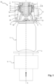
Figure 1 represents a schematic upwards view of a longitudinally sectioned sealing head according to the invention and other parts of a capsule-sealing machine according to the invention, the machine depicted in a processing station thereof for capsule-sealing a can; -
Figure 2 represents a perspective view of a can obtained by processing the capsule-sealing machine ofFigure 1 ; -
Figures 3 and 4 represent schematic views according to an A-A section ofFigure 1 respectively of some details of the sealing head offigure 1 and of a variant of the same head according to the invention. - According to the above figures, a sealing head of a capsule-sealing machine for applying a covering capsule or
capsule 1 to anupper surface 3s of acan 3 in a processing station of the same machine, as schematically illustrated infigure 1 , is indicated by 10 in its entirety. Thecan 3 is of a type comprising anupper edge 3b and an opening 3a covered by tab 3l for dispensing the contents of thesame can 3. - The sealing
head 10 and the capsule-sealing machine are for example of a type as illustrated and described in patent application N.ITBO22020325 figures 3 and 8 of the said document, is deemed to be incorporated in the present description for the sake of completeness. - More in detail, the sealing
head 10 is of a type comprising: - a plurality of circular sealing sectors, indicated in their entirety by 20, arranged around a vertical movement axis X of the same sealing
head 10 and capable of interfering, through one of their conformedlower ends 28 and the interposedcovering capsule 1, with a circumference 3i of the upper edge of thecan 3b when the can 3 approaches the sealinghead 10 during a processing phase in an capsule-sealing station of the capsule-sealing machine , - elastic means, indicated by 30 in their entirety, in coupling with the
circular sealing sectors 20 for the counteracted axial movement of the samecircular sectors 20 when they come into contact with thecovering capsule 1 and with the edge surrounding the can 3i; - heating means, for example a pair of electrical resistors with a
temperature sensing probe 12, connected to thecircular sealing sectors 20 and suitable for bringing them to a given and fixed sealing temperature. - In the example, the elastic means comprise a plurality of
helical springs 30 guided by first guide pins 14 integral with acentral body 11 of the sealinghead 10 and by second guide pins 16 integral with thecircular sealing sectors 20. In this way, saidcircular sectors 20 are integral with thecentral body 11 and cannot rotate with respect to the same. -
Figure 1 schematically illustrates, omitting details not necessary for understanding the invention, the capsule-sealing machine in correspondence with one of its can capsule-sealing stations 3 with the relative coveringcapsule 1. Note how, in an operative condition of application of the coveringcapsule 1 on the same can 3, they are coaxially aligned to the vertical axis X, in order from bottom to top: - a
pusher 4 provided with asupport surface 6 for thecan 3 to be capsule-sealed; - the can 3 to be capsule-sealed;
- the
covering capsule 1, which is connected to asuction cup device 8 for its correct positioning to cover the surface of can 3s to be capsule-sealed, - the sealing
head 10 of the type described above. - Briefly, the operation of the capsule-sealing machine provides that, in the operating condition described above, the
pusher 4 is driven to move from bottom to the top, in order to meet thecan 3 with its supportingsurface 6 and push the same upwards in the direction of the sealinghead 10, with itsupper surface 3s and relativeupper edge 3b to meet thecovering capsule 1 and then go to flow inside the sealinghead 10, interfering with thecircular sectors 20. Thecapsule 1 then adheres with one of itscentral parts 1c to theupper surface 3s by means of thesuction cup 8, with itsperipheral parts 1p to the conformedlower ends 28 of thecircular sectors 20, which are heated to a certain sealing temperature by means of the heating means 12. When the edge of thecan 3b with its surrounding 3i pushes the peripheral parts of thecapsule 1 against thecircular sectors 20, it meets the resistance of theelastic means 30 which thus exert a pressure force proportional to their stiffness on correspondent circumferential arc zones of edge 3i. Therefore, one of such zones, i.e. that corresponding to lower stiffness springs, shows a lower adhesion with the capsule and the other of such zones, namely that corresponding to higher stiffness springs, shows a higher adhesion with the capsule. - In this respect, the applicant has observed that it is possible to realize a sealing of the
capsule 1 on thecan 3 advantageously more or less strong and adhesive depending on their greater or lesser stiffness of theelastic means 30. This concept constitutes the focal point of the present invention. - Therefore, a peculiarity of the invention is that the sealing head comprises elastic means with different stiffnesses, for example comprising of helical elastic springs with decreasing stiffness, in particular progressively decreasing from 31 to 36 when respectively coupled to the circular sectors 21-26 as illustrated in
figures 3 and 4 , wherein 31 identifies the elastic spring with greater stiffness coupled to thecircular sector 21 positioned in correspondence of a distal point D to an edge of the can adjacent to the opening 3a, in particular to the circular sector positioned in correspondence of the furthest point D from the edge of the can adjacent to the opening 3i. Preferably, the elastic spring with higher stiffness is located in an angular position other than that of a mean axis of the opening so that the latter is not facing the circular sector on which the spring with higher stiffness acts. - Advantageously, as already explained, the greater stiffness of the
spring 31 means that the conformedlower end 28 of thecircular sector 21 exerts a greater compression force when far from the edge of the can adjoining the opening 3i, thus realising a seal having greater strength and stiffness than that of the other points, distancing the danger of detachment of the coveringcapsule 1 when a user takes it by one of its flaps 1l proximal to the opening 3a in order to be able to open thecan 3 and access its contents. - Elastic means, for example elastic springs 31-33 have higher stiffness when coupled to circular sectors 21-23 positioned at points distal D to an edge of the can adjoining the opening of the can 3i, lower stiffness springs 34-36 when coupled to circular sectors 24-26 positioned at points proximal P to the edge of the can adjoining the opening 3i. That is, one of the circular sectors 24-26 is facing the opening 3i and, for example, an axis of the corresponding lower stiffness spring is incident to a mean axis of the opening 3i.
- With reference to a variant of the sealing
head 10 as illustrated in the schematic section A-A of thefigure 4 , omitting some unnecessary details of the same, the circular sectors 21-23 positioned in correspondence of distal points (D) to the edge of the can adjacent to the opening 3i have a smaller circumferential extension compared to the circular sectors 24-26 positioned in correspondence of proximal points P to the edge of the can adjacent to the opening 3i, in particular they have a progressively smaller circumferential extension. - This advantageously increases the extension of areas of the sealing capsule with less stiffness and which offer less tearing resistance to a user, allowing the same to more easily detach the
capsule 1 in those areas where there is access to the tab, together decreasing the extension of the areas having the sealing instead with greater stiffness thus considerably increasing the probability that the same capsule remains attached to the can. - It is clear that further and numerous variations are possible for a skilled person in the art of the capsule-sealing machine having an improved type of sealing head for applying an covering capsule to the top surfaces of cans and the associated improved sealing head and can having the associated covering capsule according to the invention; just as it is clear that in its practical implementation the shapes of the illustrated details may be different and the same may be replaced with technically equivalent elements.
- For example, in a more sophisticated version of the sealing head, the variable stiffness spring means may comprise electronically controlled air springs, rather than other known types of mechanical spring that are equivalent to coil springs.
- According to a further embodiment not illustrated, the higher stiffness springs 24-26 are located in angular positions different from that illustrated in the figures so that the opening 3i is facing an angular sector of the edge having a lower adhesion with the capsule.
Claims (10)
- A sealing head of a capsule-sealing machine for applying a covering capsule (1) on a surface (3s) of a can (3) to be encapsulated, the can (3) comprising an edge (3b) and an opening (3a) covered by a tab (31) for spilling out a can (3) content, the sealing head (10) comprising:- first and second circular sealing sectors (20) located around a moving vertical axis (X) of the same head (10) and apt to interfere, through a shaped lower end (22) thereof, with the covering capsule (1) as inserted in between, with a can edge proximal area (3i) when the can (3) moves close to the sealing head (10) during an operative working step in an encapsulation station of the capsule-sealing machine,- first and second elastic means (30, 31-33, 34-36) being coupled with corresponding first and second sealing circular sectors (20) for a held axial moving of the same circular sectors (20, 21-23, 24-26) as soon as coming in touch with said covering capsule (1) can edge proximal areas (3i),- heating means (12) being connected to said first and second sealing circular sectors (20, 21-23, 24-26) and apt to heat them till a certain and fixed sealing temperature;characterized in that of comprising elastic means provided with different stiffness (31-36) being coupled with first and second sealing circular sectors (20, 21-23, 24-26), wherein the first sealing circular sectors (21-23) and the first elastic means (31-33) are configured to apply a higher pressure on a first circumferential arc zone of the can, and the second sealing circular sectors with the second elastic means (34- 36) are configured to apply a lower pressure on a second circumferential arc zone of the can to provide differential adhesion of the capsule on the first and second circumferential arc zones having corresponding angular extensions such that the capsule is separable from the second circumferential arc zone to open the can while remaining adherent to the first circumferential arc zone.
- Sealing head according to claim 1, wherein the first and second circumferential arcs are angularly arranged such that an opening of the can is facing said second circumferential area of the can.
- A sealing head, according to any of the previous claims, characterized in that the first elastic means comprise springs with a greater stiffness (31-33) when being coupled with sealing circular sectors (21-23) located by a distal point (D) with respect to a can edge (3i) adjoining the can opening (3a); and in that second elastic means comprise springs with a lower stiffness (34-36) when coupled with sealing circular sectors (24-26) being located next to a proximal point (P) with respect to said can edge facing the can opening (3i).
- A sealing head, according to the previous claim, characterized by comprising elastic means (31) provided with maximum stiffness when coupled with a sealing circular sector (21) located next to a distal point (D) with respect to said can edge facing the can opening (3i).
- A sealing head according to claim 4, wherein the sealing circular sector (21) is located next to the most distant point (D) with respect to the can edge adjoining the can opening (3i).
- A sealing head, according to any of the previous claim, characterized in that said second elastic means (31-36) are provided with a progressively decreasing stiffness when coupled with circular sectors (21-26) and are located next to points more distant from said circular sector (21) located next to the distal point (D) to said can edge facing the can opening (3i).
- A sealing head, according to one of the previous claims 2-6, characterized in that said first circular sectors (21-23) are provided with a circumferential extension lower than the second circular sectors (24-26).
- A sealing head according to claim 7, wherein said circumferential extension is progressively lower.
- Capsule-sealing machine of a type comprising a sealing head (10) for applying a covering capsule (1) on can surfaces (3s) comprising a tab (31) for spilling out the content thereof, comprising a working station wherein, in an operative step of applying a covering capsule (1), are coaxially aligned (X), from downtop:- a pusher (4) provided with a support surface (6) for the can to be encapsulated (3),- the can to be encapsulated (3),- a covering capsule (1), connected to a suction cup device (8) for the right location thereof in order to cover the can surface (3s) to be encapsulated,characterized in that of comprising a sealing head (10) according to one of the previous claims.
- A can provided with a covering capsule (1),
characterized in that of being produced in a working station of a capsule-sealing machine according to the previous claim.
Applications Claiming Priority (1)
| Application Number | Priority Date | Filing Date | Title |
|---|---|---|---|
| IT102020000030905A IT202000030905A1 (en) | 2020-12-15 | 2020-12-15 | ENCAPERING MACHINE EQUIPPED WITH AN IMPROVED TYPE SEALING HEAD FOR THE APPLICATION OF A COATING SHEET ON THE UPPER SURFACES OF CANS AND RELATED IMPROVED SEALING HEAD AND CAN EQUIPPED WITH A COATING SHEET. |
Publications (3)
| Publication Number | Publication Date |
|---|---|
| EP4015402A1 EP4015402A1 (en) | 2022-06-22 |
| EP4015402B1 true EP4015402B1 (en) | 2023-09-27 |
| EP4015402C0 EP4015402C0 (en) | 2023-09-27 |
Family
ID=74759390
Family Applications (1)
| Application Number | Title | Priority Date | Filing Date |
|---|---|---|---|
| EP21214924.9A Active EP4015402B1 (en) | 2020-12-15 | 2021-12-15 | Capsule-sealing machine equipped with an improved type of sealing head for applying a covering capsule to the top surfaces of cans and their improved sealing head and can equipped with the covering capsule |
Country Status (7)
| Country | Link |
|---|---|
| US (1) | US12145762B2 (en) |
| EP (1) | EP4015402B1 (en) |
| JP (1) | JP2022094952A (en) |
| CN (1) | CN114633923A (en) |
| BR (1) | BR102021025328A2 (en) |
| CA (1) | CA3142377A1 (en) |
| IT (1) | IT202000030905A1 (en) |
Families Citing this family (1)
| Publication number | Priority date | Publication date | Assignee | Title |
|---|---|---|---|---|
| IL312010A (en) * | 2021-10-08 | 2024-06-01 | Ecocaps S R L | Mechatronic and modular closing machine for food or beverage containers |
Family Cites Families (11)
| Publication number | Priority date | Publication date | Assignee | Title |
|---|---|---|---|---|
| JPH0741882B2 (en) * | 1990-10-16 | 1995-05-10 | 名古屋製酪株式会社 | Container sealing equipment |
| IT1254174B (en) * | 1991-12-24 | 1995-09-11 | Burgopack Stampa Trasformazione Imballaggi Spa | CONTAINER WITH HEAT-SEALED COVER OF THE PEELABLE TYPE WITH IMPROVED ANCHORAGE AREA |
| US5647497A (en) * | 1996-02-21 | 1997-07-15 | Labbe; Andre | Protective removable cover for beverage container |
| DE69803093T2 (en) * | 1997-10-31 | 2002-06-13 | Bantam Engineers Ltd., London | METHOD AND DEVICE FOR CLOSING CAN-BASED CONTAINERS FOR FOODSTUFFS AND BEVERAGES |
| IT1310415B1 (en) * | 1999-07-19 | 2002-02-13 | Ecobags S R L | CAN WITH DUST PROTECTION AND ANTI-sabotage AND RELATED HEAT-SEALING SYSTEM. |
| ATE317803T1 (en) * | 1999-09-30 | 2006-03-15 | Krones Ag | BEVERAGE CAN WITH A PROTECTIVE COVER AND METHOD AND DEVICE FOR ATTACHING A PROTECTIVE COVER TO BEVERAGE CANS |
| ITBO20020325A1 (en) * | 2002-05-28 | 2003-11-28 | Ecobags S R L | ENCAPSULATING MACHINE FOR CONTAINERS OF FOOD OR DRINKS |
| SG189572A1 (en) * | 2011-10-18 | 2013-05-31 | Menicon Singapore Pte Ltd | Systems and methods for multi-stage sealing of contact lens packaging |
| ITMO20130214A1 (en) * | 2013-07-26 | 2015-01-27 | Sarong Spa | CAPSULE FOR BEVERAGES AND ITS APPARATUS AND METHOD OF CONSTRUCTION |
| FR3022222B1 (en) * | 2014-06-17 | 2019-04-12 | 1/4 Vin | METHOD AND DEVICE FOR THERMOSCELLING A FILLER ON A GLASS DRINK |
| US20190016487A1 (en) * | 2016-02-26 | 2019-01-17 | Cryovac, Inc. | Heating head for packaging assembly, packaging apparatus and process, manufacturing process for making a heating head |
-
2020
- 2020-12-15 IT IT102020000030905A patent/IT202000030905A1/en unknown
-
2021
- 2021-12-13 US US17/643,981 patent/US12145762B2/en active Active
- 2021-12-14 CA CA3142377A patent/CA3142377A1/en active Pending
- 2021-12-14 JP JP2021202112A patent/JP2022094952A/en active Pending
- 2021-12-15 CN CN202111532659.8A patent/CN114633923A/en active Pending
- 2021-12-15 BR BR102021025328-2A patent/BR102021025328A2/en unknown
- 2021-12-15 EP EP21214924.9A patent/EP4015402B1/en active Active
Also Published As
| Publication number | Publication date |
|---|---|
| IT202000030905A1 (en) | 2022-06-15 |
| CA3142377A1 (en) | 2022-06-15 |
| US12145762B2 (en) | 2024-11-19 |
| EP4015402C0 (en) | 2023-09-27 |
| BR102021025328A2 (en) | 2022-06-28 |
| EP4015402A1 (en) | 2022-06-22 |
| US20220185513A1 (en) | 2022-06-16 |
| CN114633923A (en) | 2022-06-17 |
| JP2022094952A (en) | 2022-06-27 |
Similar Documents
| Publication | Publication Date | Title |
|---|---|---|
| US10343801B2 (en) | Method for sealing a metal cans with peelable lids and device therefor | |
| US9895737B2 (en) | Packaging can and method and apparatus for its manufacture | |
| EP4015402A1 (en) | Capsule-sealing machine equipped with an improved type of sealing head for applying a covering capsule to the top surfaces of cans and their improved sealing head and can equipped with the covering capsule | |
| JPH03240633A (en) | Packaging of container in plastic wrap | |
| US20030089079A1 (en) | Method for induction sealing a plastic part to a composite container | |
| JP2023501271A (en) | Sealed container provided with a device for openable connection to the enclosure | |
| RU2845506C2 (en) | Machine for sealing capsules, equipped with improved type of sealing head for applying capsule coating on upper surfaces of cans, and improved sealing head thereof and can equipped with capsule coating | |
| EP1900651B1 (en) | Apparatus for fabricating an insulated container | |
| EP1070669A1 (en) | Beverage can with a protective film and heat-sealing apparatus therefore | |
| EP3124392A1 (en) | Overcap having means which facilitate the opening of a container and the subsequent direct consumption of the content thereof | |
| RS52259B (en) | INSULATING CONTAINER MACHINE | |
| US5776303A (en) | Covering for an opening in a flexibly curving container wall | |
| NL2037855B1 (en) | Method and device for covering an opening of a container for food products | |
| EP2055641A1 (en) | Lid ring for allowing flange tilting and method for preparing and forming a lid | |
| EP4470393A1 (en) | An automatic fruit squeezing machine and a membrane arrangement for an automatic fruit squeezing machine | |
| GB2130564A (en) | Apparatus for heat sealing and crimping a skirted cap on a container | |
| EP1726525A1 (en) | Method and apparatus for sealing containers | |
| HK1234020A1 (en) | Overcap having means which facilitate the opening of a container and the subsequent direct consumption of the content thereof | |
| WO2003068630A1 (en) | A mould protecting a food cupu and food cup's protection methods | |
| ITTO20120458A1 (en) | TOGETHER CANNUCCIA FOR BEVERAGES AND METHOD FOR ITS REALIZATION |
Legal Events
| Date | Code | Title | Description |
|---|---|---|---|
| PUAI | Public reference made under article 153(3) epc to a published international application that has entered the european phase |
Free format text: ORIGINAL CODE: 0009012 |
|
| STAA | Information on the status of an ep patent application or granted ep patent |
Free format text: STATUS: THE APPLICATION HAS BEEN PUBLISHED |
|
| AK | Designated contracting states |
Kind code of ref document: A1 Designated state(s): AL AT BE BG CH CY CZ DE DK EE ES FI FR GB GR HR HU IE IS IT LI LT LU LV MC MK MT NL NO PL PT RO RS SE SI SK SM TR |
|
| STAA | Information on the status of an ep patent application or granted ep patent |
Free format text: STATUS: REQUEST FOR EXAMINATION WAS MADE |
|
| RBV | Designated contracting states (corrected) |
Designated state(s): AL AT BE BG CH CY CZ DE DK EE ES FI FR GB GR HR HU IE IS IT LI LT LU LV MC MK MT NL NO PL PT RO RS SE SI SK SM TR |
|
| 17P | Request for examination filed |
Effective date: 20221215 |
|
| GRAP | Despatch of communication of intention to grant a patent |
Free format text: ORIGINAL CODE: EPIDOSNIGR1 |
|
| STAA | Information on the status of an ep patent application or granted ep patent |
Free format text: STATUS: GRANT OF PATENT IS INTENDED |
|
| RIC1 | Information provided on ipc code assigned before grant |
Ipc: B67B 5/03 20060101ALI20230322BHEP Ipc: B65B 7/28 20060101AFI20230322BHEP |
|
| INTG | Intention to grant announced |
Effective date: 20230413 |
|
| GRAS | Grant fee paid |
Free format text: ORIGINAL CODE: EPIDOSNIGR3 |
|
| GRAA | (expected) grant |
Free format text: ORIGINAL CODE: 0009210 |
|
| STAA | Information on the status of an ep patent application or granted ep patent |
Free format text: STATUS: THE PATENT HAS BEEN GRANTED |
|
| AK | Designated contracting states |
Kind code of ref document: B1 Designated state(s): AL AT BE BG CH CY CZ DE DK EE ES FI FR GB GR HR HU IE IS IT LI LT LU LV MC MK MT NL NO PL PT RO RS SE SI SK SM TR |
|
| REG | Reference to a national code |
Ref country code: GB Ref legal event code: FG4D |
|
| REG | Reference to a national code |
Ref country code: CH Ref legal event code: EP |
|
| REG | Reference to a national code |
Ref country code: DE Ref legal event code: R096 Ref document number: 602021005456 Country of ref document: DE |
|
| REG | Reference to a national code |
Ref country code: IE Ref legal event code: FG4D |
|
| U01 | Request for unitary effect filed |
Effective date: 20231026 |
|
| U07 | Unitary effect registered |
Designated state(s): AT BE BG DE DK EE FI FR IT LT LU LV MT NL PT SE SI Effective date: 20231103 |
|
| PG25 | Lapsed in a contracting state [announced via postgrant information from national office to epo] |
Ref country code: GR Free format text: LAPSE BECAUSE OF FAILURE TO SUBMIT A TRANSLATION OF THE DESCRIPTION OR TO PAY THE FEE WITHIN THE PRESCRIBED TIME-LIMIT Effective date: 20231228 |
|
| PG25 | Lapsed in a contracting state [announced via postgrant information from national office to epo] |
Ref country code: RS Free format text: LAPSE BECAUSE OF FAILURE TO SUBMIT A TRANSLATION OF THE DESCRIPTION OR TO PAY THE FEE WITHIN THE PRESCRIBED TIME-LIMIT Effective date: 20230927 Ref country code: NO Free format text: LAPSE BECAUSE OF FAILURE TO SUBMIT A TRANSLATION OF THE DESCRIPTION OR TO PAY THE FEE WITHIN THE PRESCRIBED TIME-LIMIT Effective date: 20231227 Ref country code: HR Free format text: LAPSE BECAUSE OF FAILURE TO SUBMIT A TRANSLATION OF THE DESCRIPTION OR TO PAY THE FEE WITHIN THE PRESCRIBED TIME-LIMIT Effective date: 20230927 Ref country code: GR Free format text: LAPSE BECAUSE OF FAILURE TO SUBMIT A TRANSLATION OF THE DESCRIPTION OR TO PAY THE FEE WITHIN THE PRESCRIBED TIME-LIMIT Effective date: 20231228 |
|
| U20 | Renewal fee for the european patent with unitary effect paid |
Year of fee payment: 3 Effective date: 20231228 |
|
| PG25 | Lapsed in a contracting state [announced via postgrant information from national office to epo] |
Ref country code: IS Free format text: LAPSE BECAUSE OF FAILURE TO SUBMIT A TRANSLATION OF THE DESCRIPTION OR TO PAY THE FEE WITHIN THE PRESCRIBED TIME-LIMIT Effective date: 20240127 |
|
| PG25 | Lapsed in a contracting state [announced via postgrant information from national office to epo] |
Ref country code: ES Free format text: LAPSE BECAUSE OF FAILURE TO SUBMIT A TRANSLATION OF THE DESCRIPTION OR TO PAY THE FEE WITHIN THE PRESCRIBED TIME-LIMIT Effective date: 20230927 |
|
| PG25 | Lapsed in a contracting state [announced via postgrant information from national office to epo] |
Ref country code: SM Free format text: LAPSE BECAUSE OF FAILURE TO SUBMIT A TRANSLATION OF THE DESCRIPTION OR TO PAY THE FEE WITHIN THE PRESCRIBED TIME-LIMIT Effective date: 20230927 Ref country code: RO Free format text: LAPSE BECAUSE OF FAILURE TO SUBMIT A TRANSLATION OF THE DESCRIPTION OR TO PAY THE FEE WITHIN THE PRESCRIBED TIME-LIMIT Effective date: 20230927 Ref country code: IS Free format text: LAPSE BECAUSE OF FAILURE TO SUBMIT A TRANSLATION OF THE DESCRIPTION OR TO PAY THE FEE WITHIN THE PRESCRIBED TIME-LIMIT Effective date: 20240127 Ref country code: ES Free format text: LAPSE BECAUSE OF FAILURE TO SUBMIT A TRANSLATION OF THE DESCRIPTION OR TO PAY THE FEE WITHIN THE PRESCRIBED TIME-LIMIT Effective date: 20230927 Ref country code: CZ Free format text: LAPSE BECAUSE OF FAILURE TO SUBMIT A TRANSLATION OF THE DESCRIPTION OR TO PAY THE FEE WITHIN THE PRESCRIBED TIME-LIMIT Effective date: 20230927 Ref country code: SK Free format text: LAPSE BECAUSE OF FAILURE TO SUBMIT A TRANSLATION OF THE DESCRIPTION OR TO PAY THE FEE WITHIN THE PRESCRIBED TIME-LIMIT Effective date: 20230927 |
|
| PG25 | Lapsed in a contracting state [announced via postgrant information from national office to epo] |
Ref country code: PL Free format text: LAPSE BECAUSE OF FAILURE TO SUBMIT A TRANSLATION OF THE DESCRIPTION OR TO PAY THE FEE WITHIN THE PRESCRIBED TIME-LIMIT Effective date: 20230927 |
|
| REG | Reference to a national code |
Ref country code: DE Ref legal event code: R097 Ref document number: 602021005456 Country of ref document: DE |
|
| PLBE | No opposition filed within time limit |
Free format text: ORIGINAL CODE: 0009261 |
|
| STAA | Information on the status of an ep patent application or granted ep patent |
Free format text: STATUS: NO OPPOSITION FILED WITHIN TIME LIMIT |
|
| PG25 | Lapsed in a contracting state [announced via postgrant information from national office to epo] |
Ref country code: MC Free format text: LAPSE BECAUSE OF FAILURE TO SUBMIT A TRANSLATION OF THE DESCRIPTION OR TO PAY THE FEE WITHIN THE PRESCRIBED TIME-LIMIT Effective date: 20230927 |
|
| PG25 | Lapsed in a contracting state [announced via postgrant information from national office to epo] |
Ref country code: MC Free format text: LAPSE BECAUSE OF FAILURE TO SUBMIT A TRANSLATION OF THE DESCRIPTION OR TO PAY THE FEE WITHIN THE PRESCRIBED TIME-LIMIT Effective date: 20230927 |
|
| 26N | No opposition filed |
Effective date: 20240628 |
|
| REG | Reference to a national code |
Ref country code: IE Ref legal event code: MM4A |
|
| PG25 | Lapsed in a contracting state [announced via postgrant information from national office to epo] |
Ref country code: IE Free format text: LAPSE BECAUSE OF NON-PAYMENT OF DUE FEES Effective date: 20231215 |
|
| PG25 | Lapsed in a contracting state [announced via postgrant information from national office to epo] |
Ref country code: IE Free format text: LAPSE BECAUSE OF NON-PAYMENT OF DUE FEES Effective date: 20231215 |
|
| U20 | Renewal fee for the european patent with unitary effect paid |
Year of fee payment: 4 Effective date: 20241231 |
|
| PG25 | Lapsed in a contracting state [announced via postgrant information from national office to epo] |
Ref country code: CY Free format text: LAPSE BECAUSE OF FAILURE TO SUBMIT A TRANSLATION OF THE DESCRIPTION OR TO PAY THE FEE WITHIN THE PRESCRIBED TIME-LIMIT; INVALID AB INITIO Effective date: 20211215 |
|
| REG | Reference to a national code |
Ref country code: CH Ref legal event code: PL |
|
| PG25 | Lapsed in a contracting state [announced via postgrant information from national office to epo] |
Ref country code: CH Free format text: LAPSE BECAUSE OF NON-PAYMENT OF DUE FEES Effective date: 20241231 |
|
| PGFP | Annual fee paid to national office [announced via postgrant information from national office to epo] |
Ref country code: TR Payment date: 20251210 Year of fee payment: 5 |
|
| U20 | Renewal fee for the european patent with unitary effect paid |
Year of fee payment: 5 Effective date: 20251229 |
|
| PG25 | Lapsed in a contracting state [announced via postgrant information from national office to epo] |
Ref country code: HU Free format text: LAPSE BECAUSE OF FAILURE TO SUBMIT A TRANSLATION OF THE DESCRIPTION OR TO PAY THE FEE WITHIN THE PRESCRIBED TIME-LIMIT; INVALID AB INITIO Effective date: 20211215 |