EP4015387A1 - Ram exhaust module - Google Patents
Ram exhaust module Download PDFInfo
- Publication number
- EP4015387A1 EP4015387A1 EP21216171.5A EP21216171A EP4015387A1 EP 4015387 A1 EP4015387 A1 EP 4015387A1 EP 21216171 A EP21216171 A EP 21216171A EP 4015387 A1 EP4015387 A1 EP 4015387A1
- Authority
- EP
- European Patent Office
- Prior art keywords
- ram air
- diffuser
- fan
- flow
- air module
- Prior art date
- Legal status (The legal status is an assumption and is not a legal conclusion. Google has not performed a legal analysis and makes no representation as to the accuracy of the status listed.)
- Granted
Links
Images







Classifications
-
- B—PERFORMING OPERATIONS; TRANSPORTING
- B64—AIRCRAFT; AVIATION; COSMONAUTICS
- B64D—EQUIPMENT FOR FITTING IN OR TO AIRCRAFT; FLIGHT SUITS; PARACHUTES; ARRANGEMENT OR MOUNTING OF POWER PLANTS OR PROPULSION TRANSMISSIONS IN AIRCRAFT
- B64D13/00—Arrangements or adaptations of air-treatment apparatus for aircraft crew or passengers, or freight space
-
- B—PERFORMING OPERATIONS; TRANSPORTING
- B64—AIRCRAFT; AVIATION; COSMONAUTICS
- B64D—EQUIPMENT FOR FITTING IN OR TO AIRCRAFT; FLIGHT SUITS; PARACHUTES; ARRANGEMENT OR MOUNTING OF POWER PLANTS OR PROPULSION TRANSMISSIONS IN AIRCRAFT
- B64D13/00—Arrangements or adaptations of air-treatment apparatus for aircraft crew or passengers, or freight space
- B64D13/06—Arrangements or adaptations of air-treatment apparatus for aircraft crew or passengers, or freight space the air being conditioned
- B64D13/08—Arrangements or adaptations of air-treatment apparatus for aircraft crew or passengers, or freight space the air being conditioned the air being heated or cooled
-
- B—PERFORMING OPERATIONS; TRANSPORTING
- B64—AIRCRAFT; AVIATION; COSMONAUTICS
- B64D—EQUIPMENT FOR FITTING IN OR TO AIRCRAFT; FLIGHT SUITS; PARACHUTES; ARRANGEMENT OR MOUNTING OF POWER PLANTS OR PROPULSION TRANSMISSIONS IN AIRCRAFT
- B64D13/00—Arrangements or adaptations of air-treatment apparatus for aircraft crew or passengers, or freight space
- B64D13/02—Arrangements or adaptations of air-treatment apparatus for aircraft crew or passengers, or freight space the air being pressurised
-
- B—PERFORMING OPERATIONS; TRANSPORTING
- B64—AIRCRAFT; AVIATION; COSMONAUTICS
- B64D—EQUIPMENT FOR FITTING IN OR TO AIRCRAFT; FLIGHT SUITS; PARACHUTES; ARRANGEMENT OR MOUNTING OF POWER PLANTS OR PROPULSION TRANSMISSIONS IN AIRCRAFT
- B64D13/00—Arrangements or adaptations of air-treatment apparatus for aircraft crew or passengers, or freight space
- B64D13/02—Arrangements or adaptations of air-treatment apparatus for aircraft crew or passengers, or freight space the air being pressurised
- B64D13/04—Automatic control of pressure
-
- F—MECHANICAL ENGINEERING; LIGHTING; HEATING; WEAPONS; BLASTING
- F04—POSITIVE - DISPLACEMENT MACHINES FOR LIQUIDS; PUMPS FOR LIQUIDS OR ELASTIC FLUIDS
- F04D—NON-POSITIVE-DISPLACEMENT PUMPS
- F04D19/00—Axial-flow pumps
- F04D19/002—Axial flow fans
-
- B—PERFORMING OPERATIONS; TRANSPORTING
- B64—AIRCRAFT; AVIATION; COSMONAUTICS
- B64D—EQUIPMENT FOR FITTING IN OR TO AIRCRAFT; FLIGHT SUITS; PARACHUTES; ARRANGEMENT OR MOUNTING OF POWER PLANTS OR PROPULSION TRANSMISSIONS IN AIRCRAFT
- B64D13/00—Arrangements or adaptations of air-treatment apparatus for aircraft crew or passengers, or freight space
- B64D13/06—Arrangements or adaptations of air-treatment apparatus for aircraft crew or passengers, or freight space the air being conditioned
- B64D2013/0603—Environmental Control Systems
- B64D2013/0618—Environmental Control Systems with arrangements for reducing or managing bleed air, using another air source, e.g. ram air
-
- B—PERFORMING OPERATIONS; TRANSPORTING
- B64—AIRCRAFT; AVIATION; COSMONAUTICS
- B64D—EQUIPMENT FOR FITTING IN OR TO AIRCRAFT; FLIGHT SUITS; PARACHUTES; ARRANGEMENT OR MOUNTING OF POWER PLANTS OR PROPULSION TRANSMISSIONS IN AIRCRAFT
- B64D13/00—Arrangements or adaptations of air-treatment apparatus for aircraft crew or passengers, or freight space
- B64D13/06—Arrangements or adaptations of air-treatment apparatus for aircraft crew or passengers, or freight space the air being conditioned
- B64D2013/0603—Environmental Control Systems
- B64D2013/0688—Environmental Control Systems with means for recirculating cabin air
-
- F—MECHANICAL ENGINEERING; LIGHTING; HEATING; WEAPONS; BLASTING
- F04—POSITIVE - DISPLACEMENT MACHINES FOR LIQUIDS; PUMPS FOR LIQUIDS OR ELASTIC FLUIDS
- F04D—NON-POSITIVE-DISPLACEMENT PUMPS
- F04D29/00—Details, component parts, or accessories
- F04D29/40—Casings; Connections of working fluid
- F04D29/52—Casings; Connections of working fluid for axial pumps
- F04D29/54—Fluid-guiding means, e.g. diffusers
- F04D29/541—Specially adapted for elastic fluid pumps
- F04D29/542—Bladed diffusers
-
- F—MECHANICAL ENGINEERING; LIGHTING; HEATING; WEAPONS; BLASTING
- F04—POSITIVE - DISPLACEMENT MACHINES FOR LIQUIDS; PUMPS FOR LIQUIDS OR ELASTIC FLUIDS
- F04D—NON-POSITIVE-DISPLACEMENT PUMPS
- F04D29/00—Details, component parts, or accessories
- F04D29/40—Casings; Connections of working fluid
- F04D29/52—Casings; Connections of working fluid for axial pumps
- F04D29/54—Fluid-guiding means, e.g. diffusers
- F04D29/541—Specially adapted for elastic fluid pumps
- F04D29/545—Ducts
-
- F—MECHANICAL ENGINEERING; LIGHTING; HEATING; WEAPONS; BLASTING
- F05—INDEXING SCHEMES RELATING TO ENGINES OR PUMPS IN VARIOUS SUBCLASSES OF CLASSES F01-F04
- F05D—INDEXING SCHEME FOR ASPECTS RELATING TO NON-POSITIVE-DISPLACEMENT MACHINES OR ENGINES, GAS-TURBINES OR JET-PROPULSION PLANTS
- F05D2250/00—Geometry
- F05D2250/50—Inlet or outlet
- F05D2250/51—Inlet
-
- F—MECHANICAL ENGINEERING; LIGHTING; HEATING; WEAPONS; BLASTING
- F05—INDEXING SCHEMES RELATING TO ENGINES OR PUMPS IN VARIOUS SUBCLASSES OF CLASSES F01-F04
- F05D—INDEXING SCHEME FOR ASPECTS RELATING TO NON-POSITIVE-DISPLACEMENT MACHINES OR ENGINES, GAS-TURBINES OR JET-PROPULSION PLANTS
- F05D2250/00—Geometry
- F05D2250/50—Inlet or outlet
- F05D2250/52—Outlet
-
- F—MECHANICAL ENGINEERING; LIGHTING; HEATING; WEAPONS; BLASTING
- F05—INDEXING SCHEMES RELATING TO ENGINES OR PUMPS IN VARIOUS SUBCLASSES OF CLASSES F01-F04
- F05D—INDEXING SCHEME FOR ASPECTS RELATING TO NON-POSITIVE-DISPLACEMENT MACHINES OR ENGINES, GAS-TURBINES OR JET-PROPULSION PLANTS
- F05D2260/00—Function
- F05D2260/30—Retaining components in desired mutual position
Definitions
- Embodiments of the present disclosure relate to environmental control system for aircraft, and more specifically, to a flow control through a ram air duct of an environmental control system.
- ram air ducts are used to provide a flow of ambient air to interact with various aircraft systems.
- One or more heat exchangers are positioned within the ram air duct to cool system fluids, such as liquid in a cooling loop or air used in an air conditioning system. Airflow through the ram air duct provides a heat sink for the fluids.
- Airflow through the ram air duct provides a heat sink for the fluids.
- air is forced through the ram air duct dependent on the speed of the aircraft.
- a fan positioned within the duct is driven to provide airflow. The fan acts as a restriction on airflow during flight and it is, therefore, desirable to bypass the fan to allow sufficient airflow to cool the heat exchangers.
- a ram air module for use in a ram air system, the ram air module includes a diffuser having a diffuser body including an inlet end and an outlet end, a flow diverter assembly connected to the inlet end of the diffuser body, and a valve connected to the outlet end of the diffuser body.
- the diffuser, the flow diverter assembly, and the valve are integrally formed.
- valve may further comprise: a flange extending radially outwardly from the diffuser body adjacent the outlet end of the diffuser body, at least one bypass opening formed in the flange, and at least one valve element mounted to the flange adjacent the at least one bypass opening.
- the at least one valve element is movable between a first position when the at least one bypass opening is closed and a second position where the at least one bypass opening is at least partially open.
- At least one biasing mechanism may be operably coupled to the at least one valve element, wherein a biasing force of the at least one biasing mechanism biases the at least one valve element to the first position.
- a flow blocker may extend radially outwardly from an exterior of the diffuser body.
- FIG. 1 may depict a center body positioned within a hollow interior of the diffuser body.
- the flow diverter assembly further comprises: a nozzle, a plurality of elements extending from the nozzle, and a plurality of flow passages defined between adjacent elements of the plurality of elements.
- the plurality of elements are configured to straighten a flow as it passes through the plurality of flow passages.
- the ram air module further comprises an ejector.
- the ejector is defined by a clearance between an end of the nozzle and the inlet end of the diffuser body.
- the ram air module is receivable within a ram air duct of the ram air system.
- the diffuser, the valve, and at least a portion of the flow diverter assembly is positionable within an annular housing of the ram air duct.
- the ram air module is interconnected with an environmental control system.
- a ram air system of a vehicle includes a ram air duct having an inlet for receiving an ambient airflow and an outlet for discharging the ambient air flow overboard.
- the ram air duct comprises an annular housing and a flange connected to the annular housing.
- a ram air module is removably mountable within the annular housing.
- the ram air module includes a diffuser, a flow diverter assembly connected to the diffuser, and a valve connected to the diffuser.
- the diffuser when the ram air module is mounted within the annular housing, the diffuser defines a fan duct and a bypass duct.
- the diffuser, the flow diverter assembly, and the valve are integrally formed.
- FIG. 1 may depict a fan for moving the ambient air from the inlet to the outlet and a fan housing surrounding at least a portion of the fan.
- the fan housing is connectable with the annular housing to define a turnabout section of a flow path extending between the inlet and the outlet.
- the flow diverter assembly includes a nozzle, and when the fan housing is connected to the annular housing, the fan is positioned at least partially within the nozzle.
- an end of the nozzle is offset from an adjacent end of the diffuser by a clearance, and the clearance defines a recirculation flow path from the nozzle to an inlet of the fan.
- valve includes a check valve.
- the ram air duct is interconnected with an environmental control system.
- FIG. 1 a schematic diagram of an example of ram air system 20 interconnected with an environmental control system 10 is illustrated.
- the ram air system 20 and the environmental control system 10 may be mounted on board a vehicle, such as in an unpressurized bay of an aircraft for example.
- the environmental control system 10 is operable to condition one or more mediums provided thereto and to deliver a conditioned form of the one or more mediums to one or more loads of the aircraft, such as the cabin or a mixing unit 12 in fluid communication with the cabin for example.
- loads of the aircraft such as the cabin or a mixing unit 12 in fluid communication with the cabin for example.
- Examples of mediums that may be provided to the environmental control system include bleed air A1, fresh air A2, and air returned from a pressurized volume A3, such as the cabin.
- Bleed air A1 is pressurized air originating from i.e.
- Fresh air A2 such as outside air for example, may be procured via one or more scooping mechanisms, such as an impact scoop or a flush scoop for example.
- fresh air A2 as described herein is at an ambient pressure equal to an air pressure outside of the aircraft when the aircraft is on the ground and is between an ambient pressure and a cabin pressure when the aircraft is in flight.
- the air returned form the pressurized volume A3 may be cabin discharge air, which is air leaving the cabin and that would typically be discharged overboard.
- the environmental control system 10 illustrated herein is described in more detail in U.S. Application Serial No. 15/793,585, filed on October 25, 2017 . However, it should be understood that an environmental control system having any suitable configuration is within the scope of the disclosure.
- the ram air system 20 includes a ram air duct 22, and a fan 24 and at least one heat exchanger 26 are arranged within the interior of the ram air duct 22.
- a flow of ram air A ram through the ram air duct 22 is induced in response to flight of the aircraft.
- operation of the fan 24 is configured to pull ram air or ambient air from an inlet 30 of the ram air duct 22.
- the portion of the ram air that is output from the fan 24 near the outlet 32 of the ram air duct 22 is referred to herein as fan air.
- a portion of the ram air flowing through the ram air duct 22 is configured to bypass the fan 24.
- the ram air is configured to flow over the one or more heat exchangers 26.
- the air exhausted from the outlet of the ram air duct 22 may be discharged overboard into the ambient atmosphere surrounding the aircraft.
- At least one of the heat exchangers 26 is an air-to-air heat exchanger through which a medium, such as bleed air A1 or fresh air A2 flows.
- a medium such as bleed air A1 or fresh air A2 flows.
- the medium is cooled by the flow of ram air moving through the ram air duct 22.
- Humidity and moisture is removed from at least one medium within a portion of the environmental control system 10, such as at a location with respect to the flow of the at least one medium that is downstream from the ram air system 20.
- the ram air system 20 includes at least one spray nozzle 34 positioned generally adjacent the one or more heat exchangers 26.
- a fluid, such as water for example, removed from the one or more mediums may be supplied to the at least one spray nozzle where the fluid is directed towards the heat exchangers to provide additional cooling capacity with respect to the mediums flowing therethrough.
- a ram air module 40 is removably mountable within the ram air duct 22, such as generally adjacent the outlet 32 of the ram air duct 22.
- the ram air module 40 is an assembly or cartridge including a plurality of components of the ram air system 20, such as a diffuser and bypass check valve for example.
- the ram air module 40 includes a generally hollow body 42 having a first end 44 and a second end 46 through which a flow passes.
- the body 42 is generally frusto-conical in shape such that the diameter adjacent the first, inlet end 44 of the body 42 is smaller than the diameter of the second, outlet end 46 of the body 42.
- the cross-sectional area of the body 42 increases along the flow path defined within the interior 48 of the body 42.
- the body 42 forms a diffuser such that as ram air flows through the body 42, the velocity of the ram air is reduced, and the static pressure of the ram air is increased.
- a center body 50 is located within the hollow interior 48 of the diffuser body 42.
- the center body 50 is an elongated piece of material extending generally from the inlet end 44 to the outlet end 46 of the body 42.
- the diameter of the center body 50 may be substantially uniform over its length, or alternatively, may vary.
- One or more first de-swirl vanes 52 may be located at or near the downstream end 54 of the center body 50.
- one or more second de-swirl vanes 56 may be located at or near the upstream end 58 of the center body 50.
- the first and/or second de-swirl vanes 52, 56 may be configured to alter the direction of flow of a fluid passing across them.
- first and second de-swirl vanes 52, 56 respectively are illustrated, it should be understood that any number of first or second de-swirl vanes 52, 56, such as two, three, four, five, or more than six de-swirl vanes are contemplated herein. Further, the number of first de-swirl vanes 52 may but need not equal the number of second de-swirl vanes 56 of the center body 50.
- the de-swirl vanes 52, 56 may extend in a purely radial direction, as shown, or alternatively, may extend at an angle, in both a radial and axial direction.
- vanes may be arranged at another axial location along the center body 50 instead of or in addition to the first and second de-swirl vanes 52, 56 described herein.
- the center body 50 may be structurally supported within the interior 48 of the diffuser body 42 by the de-swirl vanes 52, 56.
- the center body 50 is integrally formed with the diffuser body as a single unitary component.
- the flow diverter assembly 60 includes a nozzle 62 and a plurality of elements 64, such as fins or diverter vanes for example, extending radially outward from the nozzle 62.
- the nozzle 62 may be a separate component mounted to the body 42, or alternatively, may be formed by the body 42 itself.
- the plurality of radial elements 64 are separated from one another by a distance to define a plurality of external flow passages 66. The distal ends of the one or more of the elements 64 may but need not be connected to a casing 68.
- the flow diverter assembly 60 may include one or more elements 70 extending circumferentially around the periphery of the nozzle 62 and separated from one another by a plurality of external flow passages 72.
- the circumferential elements 70 may extend through an opening formed in at least a portion of the plurality of radial elements 64.
- Each of the elements 64, 70 may be formed as a single element or a plurality of segmented or multi-vane elements extending between a leading edge and a trailing edge of the nozzle 62 and casing 68.
- the ram airflow A ram moving toward the radial and/or circumferential elements 64, 70 generally has an axial component and a tangential component.
- the radial and/or circumferential elements 64, 70 can be configured to straighten the flow A ram provided to the fan 24, transforming swirl kinetic energy in the airflow into static pressure rises across the elements 64, 70.
- the nozzle 62 is separated from the first end 44 of the diffuser body 42 by a distance.
- one or more mounting elements 74 may extend axially beyond the edge of the nozzle 62 for connection with the diffuser body 42.
- the mounting elements 74 may be integrally formed with the radial elements 64, as shown. However, in other embodiments, the mounting elements 74 may be separate and distinct from the radial elements 64.
- the mounting elements 74 and/or another portion of the diverter flow assembly is integrally formed with the diffuser body as a single unitary component.
- the clearance or annular passage 76 formed between the nozzle 62 and the inlet end 44 of the body 42 forms an ejector that defines a recirculation flow path.
- the recirculation flow path supplies flow from the nozzle 62 to an inlet of the fan 24 in the event that the flow provided to the fan is reduced, for instance due to clogging of a heat exchanger 26. This additional flow may increase the surge margin of the fan 24, thereby minimizing the potential for failure of the fan 24.
- a valve 80 is located at or adjacent to the second end 46 of the diffuser body 42.
- the valve 80 includes a flange 82 extending radially outwardly from the diffuser body 42, and one or more bypass openings 84 are formed in the flange 82.
- six bypass openings are shown being equidistantly spaced about the flange 82, any number of bypass openings 84 are contemplated herein.
- the diameter of the flange 82 may but need not be equal to the diameter of the casing 68 of the flow diverter assembly 60.
- a valve element 86 such as a flap or disk for example, is mounted to the flange 82 adjacent to each of the plurality of bypass openings 84.
- the valve elements 86 are movable, for example rotatable about an axis, relative to the flange 82 between a first position and a second position. When a valve element 86 is in the first position, the valve element 86 covers or closes off an adjacent bypass opening 84 such that air is not able to flow through the bypass opening 84.
- valve 80 determines how much, if any, ram air is permitted to flow directly into the outlet section as bypass air, bypassing the fan and diffuser.
- the valve elements 86 may be movable in unison or independently.
- the valve 80 is a check valve and a biasing mechanism, such as a torsion spring for example, is coupled to each valve element 86 to bias the valve element 86 into the first, closed position.
- a biasing mechanism such as a torsion spring for example
- an increase in pressure acting on the valve elements 86 opposes the biasing force of the biasing mechanism, thereby causing the valve elements 86 to rotate from the closed position to the open position.
- the valve 80 may be operably coupled to an actuator (not shown) and a controller (not shown). The actuator will adjust a position of the valve elements 86 in response to a command generated by the controller, for example in response to a sensed condition adjacent the valve 80.
- the ram air module 40 additionally includes a flange extending radially outwardly from an exterior surface of the diffuser body 42.
- the flange 88 is integrally formed with the diffuser body 42 and extends over the substantially entire length of the diffuser, such as from the first end 44 to the second end 46.
- the outward edge of the flange 88 may be supported at each end via a connection to a portion of the flow diverter assembly 60 and the valve 80, respectively.
- the flange 88 described herein forms a flow blocker that is configured to minimize recirculation around the diffuser 42.
- the ram air module 40 is positionable within the interior of the ram air duct 22.
- the ram air duct 22 includes an annular housing 90 connected to a flange 92 to define a heat exchanger section 94, an inlet section 96, an outlet section 98.
- the heat exchanger section 94 which houses the one or more heat exchangers 26, is connected to the annular housing 90 via the inlet section 96.
- an inner diameter of the annular housing 90 may be generally equal to, or greater than the outer diameter of the flow diverter assembly 60 and the flange 82 of the valve 80.
- the diffuser body 42 When the ram air module 40 is mounted within the ram air duct, the diffuser body 42 is axially aligned with the fan 24 on a central axis. As best shown in FIG. 6 , the diffuser body 42 divides the space within the annular housing 90 into a fan duct extending through the diffuser and a bypass duct arranged generally concentrically with the fan duct. In the illustrated embodiment, the airflow provided to the annular housing 90 may be a high-velocity airflow during flight.
- a turnabout section 100 is connectable to a first end 102 of the annular housing 90, such as with a booted V-flange 104 and/or a clamp 106 (see FIGS. 11 and 12 ) for example.
- the turnabout section 100 may be at least partially defined by a fan housing, or alternatively, in embodiments where the fan 24 is part of an air cycle machine (ACM) of the environmental control system 10, may be partially defined by the housing 108 of the air cycle machine. As shown in FIGS.
- ACM air cycle machine
- an end of the fan housing or housing 108 of the air cycle machine has a diameter generally equal to the end 102 of the annular housing 90 and is connectable thereto to define a fluid flow path extending from the inlet section 96 and having a 180 degree turn to direct the fluid flow from the inlet section 96 to the fan 24.
- the turnabout section 100 has a hemi-toroidal shape; however, other suitable configurations of the turnabout section 100 are also within the scope of the disclosure.
- the nozzle 62 of the flow diverter assembly 60 may couple to an end of the shroud surrounding the fan.
- a first seal 110 such as an O-ring seal for example, is positioned adjacent at a surface of the casing 68 of the flow diverter assembly 60.
- an upstream end of the nozzle 62 may have a second seal 112 such that when the ram air module 40 is installed within the ram air duct 22, the nozzle 62 is in sealing engagement with a corresponding surface of the fan or ACM housing 108.
- the fan 24 may be directly upstream from the interior of the nozzle 62 of the flow diverter assembly 60.
- valve 80 When the ram air module 40 is installed within the annular housing 90, the valve 80 is positioned adjacent a second end 114 of annular housing 90.
- the outlet section 98 includes a duct or shroud 116 that extends from the second end of the annular housing in a direction away from the diffuser body.
- a flow of ram air enters the heat exchanger section 94 of the ram air duct 22 after passing sequentially or in parallel over the one or more heat exchangers 26 located therein.
- the warmer ram air is provided to the inlet section 96 between the heat exchanger section 94 and the annular housing 90.
- the ram air flows around the diffuser body 42.
- the bypass openings 84 are closed.
- the ram air flows through the plurality of elements 64, 70 of the flow diverter assembly 60 and into the turnabout section 100.
- the turnabout section 100 redirects the flow of ram air 180 degrees from the flow out of the annular housing 90 to the fan 24. From the fan 24, the flow of ram air A ram passes through the 62 of the flow diverter assembly 60. At least a portion of the ram air A ram passes through the ejector gap and through the interior 48 of the diffuser body 42, around the center body 50, where the flow is output from the outlet end 46 of the diffuser body 42 into the outlet section 98.
- the valve 80 and fan 24 operate together to switch airflow from series flow through the annular housing 90 and the interior 48 of the diffuser body 42 to parallel flow through annular housing 90 and the interior 48 of the diffuser body 42.
- the position of the valve 80 determines how much, if any, ram air is permitted to flow directly into the outlet section 98 from the inlet section 96 as bypass air, thereby bypassing the fan 24 and the diffuser.
- the level of flow through the valve 80 is determined in part based on the flight status of the aircraft.
- the ram air module 40 as illustrated and described herein has a compact configuration that contributes to reducing the overall size of the environmental control system. Further, by forming all or a portion of the ram air module via casting or an additive manufacturing process, the cost of the components integrated into the module may be reduced compared to systems where the components are separate components. In addition, by integrating the diffuser and valve into a single cartridge or module, the module can be easily replaced in the event of damage or a failure.
Landscapes
- Engineering & Computer Science (AREA)
- Health & Medical Sciences (AREA)
- General Health & Medical Sciences (AREA)
- Pulmonology (AREA)
- Aviation & Aerospace Engineering (AREA)
- Mechanical Engineering (AREA)
- General Engineering & Computer Science (AREA)
- Structures Of Non-Positive Displacement Pumps (AREA)
- Jet Pumps And Other Pumps (AREA)
Abstract
Description
- Embodiments of the present disclosure relate to environmental control system for aircraft, and more specifically, to a flow control through a ram air duct of an environmental control system.
- In aircraft environmental control systems, ram air ducts are used to provide a flow of ambient air to interact with various aircraft systems. One or more heat exchangers are positioned within the ram air duct to cool system fluids, such as liquid in a cooling loop or air used in an air conditioning system. Airflow through the ram air duct provides a heat sink for the fluids. During flight, air is forced through the ram air duct dependent on the speed of the aircraft. When not in flight, a fan positioned within the duct is driven to provide airflow. The fan acts as a restriction on airflow during flight and it is, therefore, desirable to bypass the fan to allow sufficient airflow to cool the heat exchangers. At other times, when full heat exchanger cooling flow is not needed, it is desirable to limit interaction of the airflow with the fan to, for example, limit drag and increase fuel efficiency. However, in order to efficiently induce airflow through the duct with the fan, it is desirable to prevent airflow through the duct from bypassing the fan.
- Several components are typically positioned within the ram air duct to define a flow path to the fan or to bypass the fan. These components typically require a substantial amount of space and have a limited ease of manufacturability.
- According to one aspect, a ram air module is provided for use in a ram air system, the ram air module includes a diffuser having a diffuser body including an inlet end and an outlet end, a flow diverter assembly connected to the inlet end of the diffuser body, and a valve connected to the outlet end of the diffuser body.
- In addition to one or more of the features described above, in further embodiments the diffuser, the flow diverter assembly, and the valve are integrally formed.
- In further embodiments the valve may further comprise: a flange extending radially outwardly from the diffuser body adjacent the outlet end of the diffuser body, at least one bypass opening formed in the flange, and at least one valve element mounted to the flange adjacent the at least one bypass opening. The at least one valve element is movable between a first position when the at least one bypass opening is closed and a second position where the at least one bypass opening is at least partially open.
- In further embodiments at least one biasing mechanism may be operably coupled to the at least one valve element, wherein a biasing force of the at least one biasing mechanism biases the at least one valve element to the first position.
- In further embodiments a flow blocker may extend radially outwardly from an exterior of the diffuser body.
- Further embodiments may comprise a center body positioned within a hollow interior of the diffuser body.
- In further embodiments the flow diverter assembly further comprises: a nozzle, a plurality of elements extending from the nozzle, and a plurality of flow passages defined between adjacent elements of the plurality of elements. The plurality of elements are configured to straighten a flow as it passes through the plurality of flow passages.
- In further embodiments the ram air module further comprises an ejector.
- In further embodiments the ejector is defined by a clearance between an end of the nozzle and the inlet end of the diffuser body.
- In further embodiments the ram air module is receivable within a ram air duct of the ram air system.
- In further embodiments the diffuser, the valve, and at least a portion of the flow diverter assembly is positionable within an annular housing of the ram air duct.
- In further embodiments the ram air module is interconnected with an environmental control system.
- According to another aspect, a ram air system of a vehicle includes a ram air duct having an inlet for receiving an ambient airflow and an outlet for discharging the ambient air flow overboard. The ram air duct comprises an annular housing and a flange connected to the annular housing. A ram air module is removably mountable within the annular housing. The ram air module includes a diffuser, a flow diverter assembly connected to the diffuser, and a valve connected to the diffuser.
- In some embodiments when the ram air module is mounted within the annular housing, the diffuser defines a fan duct and a bypass duct.
- In further embodiments the diffuser, the flow diverter assembly, and the valve are integrally formed.
- Further embodiments may comprise: a fan for moving the ambient air from the inlet to the outlet and a fan housing surrounding at least a portion of the fan. The fan housing is connectable with the annular housing to define a turnabout section of a flow path extending between the inlet and the outlet.
- In further embodiments the flow diverter assembly includes a nozzle, and when the fan housing is connected to the annular housing, the fan is positioned at least partially within the nozzle.
- In further embodiments an end of the nozzle is offset from an adjacent end of the diffuser by a clearance, and the clearance defines a recirculation flow path from the nozzle to an inlet of the fan.
- In further embodiments the valve includes a check valve.
- In further embodiments the ram air duct is interconnected with an environmental control system.
- The following descriptions should not be considered limiting in any way. With reference to the accompanying drawings, like elements are numbered alike:
-
FIG. 1 is a schematic diagram of an environmental control system interconnected with a ram air system according to an embodiment; -
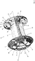
FIG. 2 is a front perspective view of a ram air module according to an embodiment; -
FIG 3 is a back perspective view of the ram air module ofFIG. 2 according to an embodiment; -
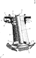
FIG 4 is a cross-sectional perspective view of the ram air module ofFIG. 2 according to an embodiment; -
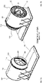
FIG. 5 is a perspective view of an environmental control system interconnected with a ram air system according to an embodiment; -
FIG. 6 is a schematic diagram of the ram air module installed within the ram air duct and interconnected with an environmental control system according to an embodiment; -
FIGS. 7A and 7B are perspective views of a ram air module installed within the ram air duct according to an embodiment; -
FIGS. 8A and 8B are front and rear views of the ram air module installed within the ram air duct ofFIGS. 7A and 7B , respectively, according to an embodiment; -
FIG. 9 is a top view of the ram air module installed within the ram air duct according to an embodiment; -
FIG. 10 is a cross-sectional view of the ram air module installed within the ram air duct ofFIG. 9 according to an embodiment; -
FIG. 11 is an exploded front perspective view of the ram air module installed within the ram air duct according to an embodiment; and -
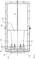
FIG. 12 is a cross-sectional view of the ram air module installed within the ram air duct ofFIG. 11 according to an embodiment. - A detailed description of one or more embodiments of the disclosed apparatus and method are presented herein by way of exemplification and not limitation with reference to the Figures.
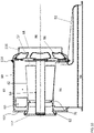
- With reference now to
FIG. 1 , a schematic diagram of an example ofram air system 20 interconnected with anenvironmental control system 10 is illustrated. Theram air system 20 and theenvironmental control system 10 may be mounted on board a vehicle, such as in an unpressurized bay of an aircraft for example. Theenvironmental control system 10 is operable to condition one or more mediums provided thereto and to deliver a conditioned form of the one or more mediums to one or more loads of the aircraft, such as the cabin or amixing unit 12 in fluid communication with the cabin for example. Examples of mediums that may be provided to the environmental control system include bleed air A1, fresh air A2, and air returned from a pressurized volume A3, such as the cabin. Bleed air A1 is pressurized air originating from i.e. being "bled" from, an engine or auxiliary power unit of the aircraft. Fresh air A2, such as outside air for example, may be procured via one or more scooping mechanisms, such as an impact scoop or a flush scoop for example. Generally, fresh air A2 as described herein is at an ambient pressure equal to an air pressure outside of the aircraft when the aircraft is on the ground and is between an ambient pressure and a cabin pressure when the aircraft is in flight. Further, the air returned form the pressurized volume A3 may be cabin discharge air, which is air leaving the cabin and that would typically be discharged overboard. Theenvironmental control system 10 illustrated herein is described in more detail inU.S. Application Serial No. 15/793,585, filed on October 25, 2017 - The
ram air system 20 includes aram air duct 22, and afan 24 and at least oneheat exchanger 26 are arranged within the interior of theram air duct 22. A flow of ram air Aram through theram air duct 22 is induced in response to flight of the aircraft. In addition, operation of thefan 24 is configured to pull ram air or ambient air from aninlet 30 of theram air duct 22. The portion of the ram air that is output from thefan 24 near theoutlet 32 of theram air duct 22 is referred to herein as fan air. However, a portion of the ram air flowing through theram air duct 22 is configured to bypass thefan 24. As the ram air flows through theram air duct 22, the ram air is configured to flow over the one ormore heat exchangers 26. Further, the air exhausted from the outlet of theram air duct 22 may be discharged overboard into the ambient atmosphere surrounding the aircraft. - In the illustrated, non-limiting embodiment, at least one of the
heat exchangers 26 is an air-to-air heat exchanger through which a medium, such as bleed air A1 or fresh air A2 flows. Within theheat exchanger 26, the medium is cooled by the flow of ram air moving through theram air duct 22. Humidity and moisture is removed from at least one medium within a portion of theenvironmental control system 10, such as at a location with respect to the flow of the at least one medium that is downstream from theram air system 20. In an embodiment, theram air system 20 includes at least onespray nozzle 34 positioned generally adjacent the one ormore heat exchangers 26. A fluid, such as water for example, removed from the one or more mediums may be supplied to the at least one spray nozzle where the fluid is directed towards the heat exchangers to provide additional cooling capacity with respect to the mediums flowing therethrough. - In an embodiment, a
ram air module 40 is removably mountable within theram air duct 22, such as generally adjacent theoutlet 32 of theram air duct 22. Theram air module 40 is an assembly or cartridge including a plurality of components of theram air system 20, such as a diffuser and bypass check valve for example. As shown, theram air module 40 includes a generallyhollow body 42 having afirst end 44 and asecond end 46 through which a flow passes. In an embodiment, thebody 42 is generally frusto-conical in shape such that the diameter adjacent the first, inlet end 44 of thebody 42 is smaller than the diameter of the second, outlet end 46 of thebody 42. As a result, the cross-sectional area of thebody 42 increases along the flow path defined within theinterior 48 of thebody 42. Thebody 42 forms a diffuser such that as ram air flows through thebody 42, the velocity of the ram air is reduced, and the static pressure of the ram air is increased. - In an embodiment, a
center body 50 is located within thehollow interior 48 of thediffuser body 42. As shown, thecenter body 50 is an elongated piece of material extending generally from theinlet end 44 to the outlet end 46 of thebody 42. The diameter of thecenter body 50 may be substantially uniform over its length, or alternatively, may vary. One or more firstde-swirl vanes 52 may be located at or near thedownstream end 54 of thecenter body 50. Alternatively, or in addition, one or more secondde-swirl vanes 56 may be located at or near theupstream end 58 of thecenter body 50. The first and/or secondde-swirl vanes center body 50 having six first and secondde-swirl vanes de-swirl vanes de-swirl vanes 52 may but need not equal the number of secondde-swirl vanes 56 of thecenter body 50. Thede-swirl vanes center body 50 instead of or in addition to the first and secondde-swirl vanes center body 50 may be structurally supported within theinterior 48 of thediffuser body 42 by thede-swirl vanes center body 50 is integrally formed with the diffuser body as a single unitary component. - Arranged at the exterior of the
body 42 adjacent the first,inlet end 44 is aflow diverter assembly 60. Theflow diverter assembly 60 includes anozzle 62 and a plurality ofelements 64, such as fins or diverter vanes for example, extending radially outward from thenozzle 62. Thenozzle 62 may be a separate component mounted to thebody 42, or alternatively, may be formed by thebody 42 itself. The plurality ofradial elements 64 are separated from one another by a distance to define a plurality ofexternal flow passages 66. The distal ends of the one or more of theelements 64 may but need not be connected to acasing 68. - Alternatively, or in addition to the plurality of
radial elements 64, theflow diverter assembly 60 may include one ormore elements 70 extending circumferentially around the periphery of thenozzle 62 and separated from one another by a plurality ofexternal flow passages 72. When theflow diverter assembly 60 includes both radial andcircumferential elements circumferential elements 70 may extend through an opening formed in at least a portion of the plurality ofradial elements 64. Each of theelements nozzle 62 andcasing 68. - In an embodiment, the ram airflow Aram moving toward the radial and/or
circumferential elements circumferential elements fan 24, transforming swirl kinetic energy in the airflow into static pressure rises across theelements - In the illustrated, non-limiting embodiment, the
nozzle 62 is separated from thefirst end 44 of thediffuser body 42 by a distance. In such embodiments, one or moremounting elements 74 may extend axially beyond the edge of thenozzle 62 for connection with thediffuser body 42. In an embodiment, the mountingelements 74 may be integrally formed with theradial elements 64, as shown. However, in other embodiments, the mountingelements 74 may be separate and distinct from theradial elements 64. In an embodiment, the mountingelements 74 and/or another portion of the diverter flow assembly is integrally formed with the diffuser body as a single unitary component. - The clearance or
annular passage 76 formed between thenozzle 62 and theinlet end 44 of thebody 42 forms an ejector that defines a recirculation flow path. The recirculation flow path supplies flow from thenozzle 62 to an inlet of thefan 24 in the event that the flow provided to the fan is reduced, for instance due to clogging of aheat exchanger 26. This additional flow may increase the surge margin of thefan 24, thereby minimizing the potential for failure of thefan 24. - In an embodiment, a
valve 80 is located at or adjacent to thesecond end 46 of thediffuser body 42. As shown, thevalve 80 includes aflange 82 extending radially outwardly from thediffuser body 42, and one ormore bypass openings 84 are formed in theflange 82. Although six bypass openings are shown being equidistantly spaced about theflange 82, any number ofbypass openings 84 are contemplated herein. Further, the diameter of theflange 82 may but need not be equal to the diameter of thecasing 68 of theflow diverter assembly 60. - In the illustrated, non-limiting embodiment, a
valve element 86, such as a flap or disk for example, is mounted to theflange 82 adjacent to each of the plurality ofbypass openings 84. As shown, thevalve elements 86 are movable, for example rotatable about an axis, relative to theflange 82 between a first position and a second position. When avalve element 86 is in the first position, thevalve element 86 covers or closes off anadjacent bypass opening 84 such that air is not able to flow through thebypass opening 84. Similarly, when thevalve element 86 is in the second position, at least a portion theadjacent bypass opening 84 is exposed (not closed by a valve element 86) and therefore a flow is able to pass through thebypass opening 84. Accordingly, operation of thevalve 80 determines how much, if any, ram air is permitted to flow directly into the outlet section as bypass air, bypassing the fan and diffuser. - The
valve elements 86 may be movable in unison or independently. In an embodiment, thevalve 80 is a check valve and a biasing mechanism, such as a torsion spring for example, is coupled to eachvalve element 86 to bias thevalve element 86 into the first, closed position. In instances where thevalve 80 is a check valve, an increase in pressure acting on thevalve elements 86 opposes the biasing force of the biasing mechanism, thereby causing thevalve elements 86 to rotate from the closed position to the open position. However, in other embodiments, thevalve 80 may be operably coupled to an actuator (not shown) and a controller (not shown). The actuator will adjust a position of thevalve elements 86 in response to a command generated by the controller, for example in response to a sensed condition adjacent thevalve 80. - In an embodiment, the
ram air module 40 additionally includes a flange extending radially outwardly from an exterior surface of thediffuser body 42. As shown, theflange 88 is integrally formed with thediffuser body 42 and extends over the substantially entire length of the diffuser, such as from thefirst end 44 to thesecond end 46. The outward edge of theflange 88 may be supported at each end via a connection to a portion of theflow diverter assembly 60 and thevalve 80, respectively. Theflange 88 described herein forms a flow blocker that is configured to minimize recirculation around thediffuser 42. - The
ram air module 40 is positionable within the interior of theram air duct 22. With reference toFIGS. 5-12 , in an embodiment, theram air duct 22 includes anannular housing 90 connected to aflange 92 to define aheat exchanger section 94, aninlet section 96, anoutlet section 98. Theheat exchanger section 94, which houses the one ormore heat exchangers 26, is connected to theannular housing 90 via theinlet section 96. In an embodiment, an inner diameter of theannular housing 90 may be generally equal to, or greater than the outer diameter of theflow diverter assembly 60 and theflange 82 of thevalve 80. When theram air module 40 is mounted within the ram air duct, thediffuser body 42 is axially aligned with thefan 24 on a central axis. As best shown inFIG. 6 , thediffuser body 42 divides the space within theannular housing 90 into a fan duct extending through the diffuser and a bypass duct arranged generally concentrically with the fan duct. In the illustrated embodiment, the airflow provided to theannular housing 90 may be a high-velocity airflow during flight. - A
turnabout section 100 is connectable to afirst end 102 of theannular housing 90, such as with a booted V-flange 104 and/or a clamp 106 (seeFIGS. 11 and12 ) for example. Theturnabout section 100 may be at least partially defined by a fan housing, or alternatively, in embodiments where thefan 24 is part of an air cycle machine (ACM) of theenvironmental control system 10, may be partially defined by thehousing 108 of the air cycle machine. As shown inFIGS. 5 and6 , an end of the fan housing orhousing 108 of the air cycle machine has a diameter generally equal to theend 102 of theannular housing 90 and is connectable thereto to define a fluid flow path extending from theinlet section 96 and having a 180 degree turn to direct the fluid flow from theinlet section 96 to thefan 24. In the illustrated, non-limiting embodiment theturnabout section 100 has a hemi-toroidal shape; however, other suitable configurations of theturnabout section 100 are also within the scope of the disclosure. - When the
turnabout section 100 is coupled to theannular housing 90, thenozzle 62 of theflow diverter assembly 60 may couple to an end of the shroud surrounding the fan. In an embodiment, afirst seal 110, such as an O-ring seal for example, is positioned adjacent at a surface of thecasing 68 of theflow diverter assembly 60. Alternatively, or in addition, an upstream end of thenozzle 62, best shown inFIG. 3 , may have asecond seal 112 such that when theram air module 40 is installed within theram air duct 22, thenozzle 62 is in sealing engagement with a corresponding surface of the fan orACM housing 108. In embodiments including this sealing engagement, thefan 24 may be directly upstream from the interior of thenozzle 62 of theflow diverter assembly 60. - When the
ram air module 40 is installed within theannular housing 90, thevalve 80 is positioned adjacent asecond end 114 ofannular housing 90. Theoutlet section 98 includes a duct orshroud 116 that extends from the second end of the annular housing in a direction away from the diffuser body. - In operation, a flow of ram air enters the
heat exchanger section 94 of theram air duct 22 after passing sequentially or in parallel over the one ormore heat exchangers 26 located therein. From theheat exchanger section 94, the warmer ram air is provided to theinlet section 96 between theheat exchanger section 94 and theannular housing 90. Within theannular housing 90, the ram air flows around thediffuser body 42. When the pressure of the ram air within theannular housing 90 is set below a threshold associated with movement of thevalve elements 86 of thecheck valve 80, thebypass openings 84 are closed. As a result, the ram air flows through the plurality ofelements flow diverter assembly 60 and into theturnabout section 100. Theturnabout section 100 redirects the flow of ram air 180 degrees from the flow out of theannular housing 90 to thefan 24. From thefan 24, the flow of ram air Aram passes through the 62 of theflow diverter assembly 60. At least a portion of the ram air Aram passes through the ejector gap and through the interior 48 of thediffuser body 42, around thecenter body 50, where the flow is output from the outlet end 46 of thediffuser body 42 into theoutlet section 98. - The
valve 80 andfan 24 operate together to switch airflow from series flow through theannular housing 90 and the interior 48 of thediffuser body 42 to parallel flow throughannular housing 90 and the interior 48 of thediffuser body 42. The position of thevalve 80 determines how much, if any, ram air is permitted to flow directly into theoutlet section 98 from theinlet section 96 as bypass air, thereby bypassing thefan 24 and the diffuser. In an embodiment, the level of flow through thevalve 80 is determined in part based on the flight status of the aircraft. - The
ram air module 40 as illustrated and described herein has a compact configuration that contributes to reducing the overall size of the environmental control system. Further, by forming all or a portion of the ram air module via casting or an additive manufacturing process, the cost of the components integrated into the module may be reduced compared to systems where the components are separate components. In addition, by integrating the diffuser and valve into a single cartridge or module, the module can be easily replaced in the event of damage or a failure. - The term "about" is intended to include the degree of error associated with measurement of the particular quantity based upon the equipment available at the time of filing the application.
- The terminology used herein is for the purpose of describing particular embodiments only and is not intended to be limiting of the present disclosure. As used herein, the singular forms "a", "an" and "the" are intended to include the plural forms as well, unless the context clearly indicates otherwise. It will be further understood that the terms "comprises" and/or "comprising," when used in this specification, specify the presence of stated features, integers, steps, operations, elements, and/or components, but do not preclude the presence or addition of one or more other features, integers, steps, operations, element components, and/or groups thereof.
- While the present disclosure has been described with reference to an exemplary embodiment or embodiments, it will be understood by those skilled in the art that various changes may be made without departing from the scope of the invention as defined by the claims. In addition, many modifications may be made to adapt a particular situation or material to the teachings of the present disclosure without departing from the essential scope thereof. Therefore, it is intended that the present disclosure not be limited to the particular embodiment disclosed as the best mode contemplated for carrying out this present disclosure, but that the present disclosure will include all embodiments falling within the scope of the claims.
Claims (15)
- A ram air module for use in a ram air system, the ram air module comprising:a diffuser having a diffuser body (42) including an inlet end (44) and an outlet end (46);a flow diverter assembly (60) connected to the inlet end of the diffuser body; anda valve (80) connected to the outlet end of the diffuser body.
- The ram air module of claim 1, wherein the diffuser, the flow diverter assembly, and the valve are integrally formed.
- The ram air module of claim 1 or 2, wherein the valve further comprises:a flange (82) extending radially outwardly from the diffuser body adjacent the outlet end of the diffuser body;at least one bypass opening (84) formed in the flange; andat least one valve element (86) mounted to the flange adjacent the at least one bypass opening, the at least one valve element being movable between a first position when the at least one bypass opening is closed and a second position where the at least one bypass opening is at least partially open.
- The ram air module of claim 3, further comprising at least one biasing mechanism operably coupled to the at least one valve element, wherein a biasing force of the at least one biasing mechanism biases the at least one valve element to the first position.
- The ram air module of any preceding claim, further comprising a flow blocker (88) extending radially outwardly from an exterior of the diffuser body.
- The ram air module of any preceding claim, further comprising a center body (50) positioned within a hollow interior of the diffuser body.
- The ram air module of any preceding claim, wherein the flow diverter assembly further comprises:a nozzle (62);a plurality of elements (64) extending from the nozzle; anda plurality of flow passages (66) defined between adjacent elements of the plurality of elements, wherein the plurality of elements are configured to straighten a flow as it passes through the plurality of flow passages.
- The ram air module of claim 7, wherein the ram air module further comprises an ejector, and optionally wherein the ejector is defined by a clearance between an end of the nozzle and the inlet end of the diffuser body.
- The ram air module of any preceding claim, wherein the ram air module is receivable within a ram air duct of the ram air system, and optionally wherein the diffuser, the valve, and at least a portion of the flow diverter assembly is positionable within an annular housing of the ram air duct.
- The ram air module of any preceding claim, wherein the ram air module is interconnected with an environmental control system.
- A ram air system of a vehicle comprising:
a ram air duct (22) having an inlet (30) for receiving an ambient airflow and an outlet (32) for discharging the ambient air flow overboard, the ram air duct comprising:an annular housing (90); anda flange (92) connected to the annular housing; anda ram air module (40) as claimed in any preceding claims removably mountable within the annular housing. - The ram air system of claim 11, wherein when the ram air module is mounted within the annular housing, the diffuser defines a fan duct and a bypass duct.
- The ram air system of claim 11 or 12, further comprising:a fan (24) for moving the ambient air from the inlet to the outlet; anda fan housing surrounding at least a portion of the fan, wherein the fan housing is connectable with the annular housing to define a turnabout section of a flow path extending between the inlet and the outlet.
- The ram air system of claim 13, wherein the flow diverter assembly includes a nozzle, and when the fan housing is connected to the annular housing, the fan is positioned at least partially within the nozzle, and optionally wherein an end of the nozzle is offset from an adjacent end of the diffuser by a clearance, and the clearance defines a recirculation flow path from the nozzle to an inlet of the fan.
- The ram air system of any of claims 11 to 14, wherein the valve includes a check valve.
Applications Claiming Priority (1)
| Application Number | Priority Date | Filing Date | Title |
|---|---|---|---|
| US17/126,893 US12043392B2 (en) | 2020-12-18 | 2020-12-18 | Ram exhaust module |
Publications (2)
| Publication Number | Publication Date |
|---|---|
| EP4015387A1 true EP4015387A1 (en) | 2022-06-22 |
| EP4015387B1 EP4015387B1 (en) | 2024-07-03 |
Family
ID=78957879
Family Applications (1)
| Application Number | Title | Priority Date | Filing Date |
|---|---|---|---|
| EP21216171.5A Active EP4015387B1 (en) | 2020-12-18 | 2021-12-20 | Ram exhaust module |
Country Status (2)
| Country | Link |
|---|---|
| US (1) | US12043392B2 (en) |
| EP (1) | EP4015387B1 (en) |
Families Citing this family (6)
| Publication number | Priority date | Publication date | Assignee | Title |
|---|---|---|---|---|
| US11802736B2 (en) | 2020-07-29 | 2023-10-31 | Hamilton Sundstrand Corporation | Annular heat exchanger |
| EP3945276B1 (en) * | 2020-07-29 | 2023-11-22 | Hamilton Sundstrand Corporation | Environmental control system |
| WO2025144657A1 (en) * | 2023-12-28 | 2025-07-03 | Beehive Industries, LLC | Two stream diffuser integrated as a single unit for use in a turbofan jet engine |
| US12467469B2 (en) * | 2024-05-03 | 2025-11-11 | Hamilton Sundstrand Corporation | Ram air fan including additively manufactured heat exchanger insert |
| US20260022897A1 (en) * | 2024-05-03 | 2026-01-22 | Hamilton Sundstrand Corporation | Ram air fan including additively manufactured heat exchanger insert |
| US20260009404A1 (en) * | 2024-07-03 | 2026-01-08 | Hamilton Sundstrand Corporation | Additively manufactured integral shaft and motor rotor heat exchanger and tie rod for ram air fan |
Citations (5)
| Publication number | Priority date | Publication date | Assignee | Title |
|---|---|---|---|---|
| DE10119433C1 (en) * | 2001-04-20 | 2002-08-22 | Liebherr Aerospace Gmbh | Ram air duct for an aircraft air conditioning system |
| EP2383185A2 (en) * | 2010-04-27 | 2011-11-02 | Hamilton Sundstrand Corporation | Ram flow modulation valve |
| EP2746160A2 (en) * | 2012-12-21 | 2014-06-25 | Hamilton Sundstrand Corporation | Ejector assembly |
| US20160097401A1 (en) * | 2014-10-01 | 2016-04-07 | Hamilton Sundstrand Corporation | Air cycle machine strut plate assembly |
| EP3385171A1 (en) * | 2017-04-07 | 2018-10-10 | Hamilton Sundstrand Corporation | Fan bypass and shutoff check valve |
Family Cites Families (4)
| Publication number | Priority date | Publication date | Assignee | Title |
|---|---|---|---|---|
| US3471080A (en) * | 1968-06-13 | 1969-10-07 | United Aircraft Corp | Low noise generation fan |
| US5031513A (en) * | 1989-10-11 | 1991-07-16 | Sundstrand Corporation | Airflow control system for a pod |
| US9267512B2 (en) * | 2011-10-24 | 2016-02-23 | Hamilton Sundstrand Corporation | Ram air fan diffuser with perforated side walls |
| US10487848B2 (en) | 2017-04-06 | 2019-11-26 | Hamilton Sundstrand Corporation | Fan inlet diffuser housing for an air cycle machine system |
-
2020
- 2020-12-18 US US17/126,893 patent/US12043392B2/en active Active
-
2021
- 2021-12-20 EP EP21216171.5A patent/EP4015387B1/en active Active
Patent Citations (5)
| Publication number | Priority date | Publication date | Assignee | Title |
|---|---|---|---|---|
| DE10119433C1 (en) * | 2001-04-20 | 2002-08-22 | Liebherr Aerospace Gmbh | Ram air duct for an aircraft air conditioning system |
| EP2383185A2 (en) * | 2010-04-27 | 2011-11-02 | Hamilton Sundstrand Corporation | Ram flow modulation valve |
| EP2746160A2 (en) * | 2012-12-21 | 2014-06-25 | Hamilton Sundstrand Corporation | Ejector assembly |
| US20160097401A1 (en) * | 2014-10-01 | 2016-04-07 | Hamilton Sundstrand Corporation | Air cycle machine strut plate assembly |
| EP3385171A1 (en) * | 2017-04-07 | 2018-10-10 | Hamilton Sundstrand Corporation | Fan bypass and shutoff check valve |
Also Published As
| Publication number | Publication date |
|---|---|
| US20220194600A1 (en) | 2022-06-23 |
| US12043392B2 (en) | 2024-07-23 |
| EP4015387B1 (en) | 2024-07-03 |
Similar Documents
| Publication | Publication Date | Title |
|---|---|---|
| EP4015387B1 (en) | Ram exhaust module | |
| US5505587A (en) | RAM air turbine generating apparatus | |
| US9771873B2 (en) | Bifurcation fairing | |
| EP3248880B1 (en) | Mixing ram and bleed air in a dual entry turbine system | |
| US11230972B2 (en) | Refreshing heat management fluid in a turbomachine | |
| EP1141522B1 (en) | Low drag ducted ram air turbine generator and cooling system | |
| CA2743279C (en) | Cooler in nacelle with radial coolant | |
| EP1820949B1 (en) | Gas turbine engine having foreign matter removal passage | |
| GB2111601A (en) | Combined surge bleed and dust removal system for a fan-jet engine | |
| EP0357173A1 (en) | Inlet particle separator de-icing system | |
| EP3339175B1 (en) | Motor cooling circuit with integrated fod particle separator | |
| JP2017082792A (en) | Cyclonic separator for turbine engine | |
| WO2018026507A1 (en) | Oil cooling systems for a gas turbine engine | |
| JP2017129117A (en) | Inlet particle separator for turbine engine | |
| US20020189263A1 (en) | Bleed valve assembly | |
| US9989070B2 (en) | Air cycle machine strut plate assembly | |
| CN113123878B (en) | Variable area measurement with different α | |
| US8511095B2 (en) | Flow discharge device | |
| US6817572B2 (en) | Air intake system of a propeller-turbine engine | |
| US11780592B2 (en) | Environmental control system pack | |
| US11492998B2 (en) | Flexible aft cowls for aircraft | |
| US6045088A (en) | Aircraft air conditioning energy recovery device | |
| CN114340999B (en) | Nacelle internal structure for a turbomachine | |
| US11066992B2 (en) | Aircraft propulsion assembly comprising a cold bleed air intake device with variable aerodynamic profile | |
| EP4431396B1 (en) | Air-conducting structure for an aircraft, air ejector or ejector pump, and aircraft |
Legal Events
| Date | Code | Title | Description |
|---|---|---|---|
| PUAI | Public reference made under article 153(3) epc to a published international application that has entered the european phase |
Free format text: ORIGINAL CODE: 0009012 |
|
| STAA | Information on the status of an ep patent application or granted ep patent |
Free format text: STATUS: THE APPLICATION HAS BEEN PUBLISHED |
|
| AK | Designated contracting states |
Kind code of ref document: A1 Designated state(s): AL AT BE BG CH CY CZ DE DK EE ES FI FR GB GR HR HU IE IS IT LI LT LU LV MC MK MT NL NO PL PT RO RS SE SI SK SM TR |
|
| STAA | Information on the status of an ep patent application or granted ep patent |
Free format text: STATUS: REQUEST FOR EXAMINATION WAS MADE |
|
| 17P | Request for examination filed |
Effective date: 20221222 |
|
| RBV | Designated contracting states (corrected) |
Designated state(s): AL AT BE BG CH CY CZ DE DK EE ES FI FR GB GR HR HU IE IS IT LI LT LU LV MC MK MT NL NO PL PT RO RS SE SI SK SM TR |
|
| GRAP | Despatch of communication of intention to grant a patent |
Free format text: ORIGINAL CODE: EPIDOSNIGR1 |
|
| STAA | Information on the status of an ep patent application or granted ep patent |
Free format text: STATUS: GRANT OF PATENT IS INTENDED |
|
| INTG | Intention to grant announced |
Effective date: 20240201 |
|
| GRAS | Grant fee paid |
Free format text: ORIGINAL CODE: EPIDOSNIGR3 |
|
| GRAA | (expected) grant |
Free format text: ORIGINAL CODE: 0009210 |
|
| STAA | Information on the status of an ep patent application or granted ep patent |
Free format text: STATUS: THE PATENT HAS BEEN GRANTED |
|
| AK | Designated contracting states |
Kind code of ref document: B1 Designated state(s): AL AT BE BG CH CY CZ DE DK EE ES FI FR GB GR HR HU IE IS IT LI LT LU LV MC MK MT NL NO PL PT RO RS SE SI SK SM TR |
|
| REG | Reference to a national code |
Ref country code: CH Ref legal event code: EP |
|
| REG | Reference to a national code |
Ref country code: DE Ref legal event code: R096 Ref document number: 602021015112 Country of ref document: DE |
|
| REG | Reference to a national code |
Ref country code: LT Ref legal event code: MG9D |
|
| REG | Reference to a national code |
Ref country code: NL Ref legal event code: MP Effective date: 20240703 |
|
| PG25 | Lapsed in a contracting state [announced via postgrant information from national office to epo] |
Ref country code: PT Free format text: LAPSE BECAUSE OF FAILURE TO SUBMIT A TRANSLATION OF THE DESCRIPTION OR TO PAY THE FEE WITHIN THE PRESCRIBED TIME-LIMIT Effective date: 20241104 |
|
| REG | Reference to a national code |
Ref country code: AT Ref legal event code: MK05 Ref document number: 1699577 Country of ref document: AT Kind code of ref document: T Effective date: 20240703 |
|
| PG25 | Lapsed in a contracting state [announced via postgrant information from national office to epo] |
Ref country code: NL Free format text: LAPSE BECAUSE OF FAILURE TO SUBMIT A TRANSLATION OF THE DESCRIPTION OR TO PAY THE FEE WITHIN THE PRESCRIBED TIME-LIMIT Effective date: 20240703 |
|
| PG25 | Lapsed in a contracting state [announced via postgrant information from national office to epo] |
Ref country code: PT Free format text: LAPSE BECAUSE OF FAILURE TO SUBMIT A TRANSLATION OF THE DESCRIPTION OR TO PAY THE FEE WITHIN THE PRESCRIBED TIME-LIMIT Effective date: 20241104 Ref country code: NL Free format text: LAPSE BECAUSE OF FAILURE TO SUBMIT A TRANSLATION OF THE DESCRIPTION OR TO PAY THE FEE WITHIN THE PRESCRIBED TIME-LIMIT Effective date: 20240703 |
|
| PG25 | Lapsed in a contracting state [announced via postgrant information from national office to epo] |
Ref country code: NO Free format text: LAPSE BECAUSE OF FAILURE TO SUBMIT A TRANSLATION OF THE DESCRIPTION OR TO PAY THE FEE WITHIN THE PRESCRIBED TIME-LIMIT Effective date: 20241003 |
|
| PG25 | Lapsed in a contracting state [announced via postgrant information from national office to epo] |
Ref country code: FI Free format text: LAPSE BECAUSE OF FAILURE TO SUBMIT A TRANSLATION OF THE DESCRIPTION OR TO PAY THE FEE WITHIN THE PRESCRIBED TIME-LIMIT Effective date: 20240703 Ref country code: GR Free format text: LAPSE BECAUSE OF FAILURE TO SUBMIT A TRANSLATION OF THE DESCRIPTION OR TO PAY THE FEE WITHIN THE PRESCRIBED TIME-LIMIT Effective date: 20241004 Ref country code: PL Free format text: LAPSE BECAUSE OF FAILURE TO SUBMIT A TRANSLATION OF THE DESCRIPTION OR TO PAY THE FEE WITHIN THE PRESCRIBED TIME-LIMIT Effective date: 20240703 |
|
| PG25 | Lapsed in a contracting state [announced via postgrant information from national office to epo] |
Ref country code: BG Free format text: LAPSE BECAUSE OF FAILURE TO SUBMIT A TRANSLATION OF THE DESCRIPTION OR TO PAY THE FEE WITHIN THE PRESCRIBED TIME-LIMIT Effective date: 20240703 |
|
| PG25 | Lapsed in a contracting state [announced via postgrant information from national office to epo] |
Ref country code: LV Free format text: LAPSE BECAUSE OF FAILURE TO SUBMIT A TRANSLATION OF THE DESCRIPTION OR TO PAY THE FEE WITHIN THE PRESCRIBED TIME-LIMIT Effective date: 20240703 |
|
| PG25 | Lapsed in a contracting state [announced via postgrant information from national office to epo] |
Ref country code: IS Free format text: LAPSE BECAUSE OF FAILURE TO SUBMIT A TRANSLATION OF THE DESCRIPTION OR TO PAY THE FEE WITHIN THE PRESCRIBED TIME-LIMIT Effective date: 20241103 Ref country code: AT Free format text: LAPSE BECAUSE OF FAILURE TO SUBMIT A TRANSLATION OF THE DESCRIPTION OR TO PAY THE FEE WITHIN THE PRESCRIBED TIME-LIMIT Effective date: 20240703 |
|
| PG25 | Lapsed in a contracting state [announced via postgrant information from national office to epo] |
Ref country code: CZ Free format text: LAPSE BECAUSE OF FAILURE TO SUBMIT A TRANSLATION OF THE DESCRIPTION OR TO PAY THE FEE WITHIN THE PRESCRIBED TIME-LIMIT Effective date: 20240703 Ref country code: HR Free format text: LAPSE BECAUSE OF FAILURE TO SUBMIT A TRANSLATION OF THE DESCRIPTION OR TO PAY THE FEE WITHIN THE PRESCRIBED TIME-LIMIT Effective date: 20240703 |
|
| PG25 | Lapsed in a contracting state [announced via postgrant information from national office to epo] |
Ref country code: ES Free format text: LAPSE BECAUSE OF FAILURE TO SUBMIT A TRANSLATION OF THE DESCRIPTION OR TO PAY THE FEE WITHIN THE PRESCRIBED TIME-LIMIT Effective date: 20240703 Ref country code: RS Free format text: LAPSE BECAUSE OF FAILURE TO SUBMIT A TRANSLATION OF THE DESCRIPTION OR TO PAY THE FEE WITHIN THE PRESCRIBED TIME-LIMIT Effective date: 20241003 |
|
| PG25 | Lapsed in a contracting state [announced via postgrant information from national office to epo] |
Ref country code: RS Free format text: LAPSE BECAUSE OF FAILURE TO SUBMIT A TRANSLATION OF THE DESCRIPTION OR TO PAY THE FEE WITHIN THE PRESCRIBED TIME-LIMIT Effective date: 20241003 Ref country code: PL Free format text: LAPSE BECAUSE OF FAILURE TO SUBMIT A TRANSLATION OF THE DESCRIPTION OR TO PAY THE FEE WITHIN THE PRESCRIBED TIME-LIMIT Effective date: 20240703 Ref country code: NO Free format text: LAPSE BECAUSE OF FAILURE TO SUBMIT A TRANSLATION OF THE DESCRIPTION OR TO PAY THE FEE WITHIN THE PRESCRIBED TIME-LIMIT Effective date: 20241003 Ref country code: LV Free format text: LAPSE BECAUSE OF FAILURE TO SUBMIT A TRANSLATION OF THE DESCRIPTION OR TO PAY THE FEE WITHIN THE PRESCRIBED TIME-LIMIT Effective date: 20240703 Ref country code: IS Free format text: LAPSE BECAUSE OF FAILURE TO SUBMIT A TRANSLATION OF THE DESCRIPTION OR TO PAY THE FEE WITHIN THE PRESCRIBED TIME-LIMIT Effective date: 20241103 Ref country code: HR Free format text: LAPSE BECAUSE OF FAILURE TO SUBMIT A TRANSLATION OF THE DESCRIPTION OR TO PAY THE FEE WITHIN THE PRESCRIBED TIME-LIMIT Effective date: 20240703 Ref country code: GR Free format text: LAPSE BECAUSE OF FAILURE TO SUBMIT A TRANSLATION OF THE DESCRIPTION OR TO PAY THE FEE WITHIN THE PRESCRIBED TIME-LIMIT Effective date: 20241004 Ref country code: FI Free format text: LAPSE BECAUSE OF FAILURE TO SUBMIT A TRANSLATION OF THE DESCRIPTION OR TO PAY THE FEE WITHIN THE PRESCRIBED TIME-LIMIT Effective date: 20240703 Ref country code: ES Free format text: LAPSE BECAUSE OF FAILURE TO SUBMIT A TRANSLATION OF THE DESCRIPTION OR TO PAY THE FEE WITHIN THE PRESCRIBED TIME-LIMIT Effective date: 20240703 Ref country code: CZ Free format text: LAPSE BECAUSE OF FAILURE TO SUBMIT A TRANSLATION OF THE DESCRIPTION OR TO PAY THE FEE WITHIN THE PRESCRIBED TIME-LIMIT Effective date: 20240703 Ref country code: BG Free format text: LAPSE BECAUSE OF FAILURE TO SUBMIT A TRANSLATION OF THE DESCRIPTION OR TO PAY THE FEE WITHIN THE PRESCRIBED TIME-LIMIT Effective date: 20240703 Ref country code: AT Free format text: LAPSE BECAUSE OF FAILURE TO SUBMIT A TRANSLATION OF THE DESCRIPTION OR TO PAY THE FEE WITHIN THE PRESCRIBED TIME-LIMIT Effective date: 20240703 |
|
| REG | Reference to a national code |
Ref country code: DE Ref legal event code: R097 Ref document number: 602021015112 Country of ref document: DE |
|
| PG25 | Lapsed in a contracting state [announced via postgrant information from national office to epo] |
Ref country code: RO Free format text: LAPSE BECAUSE OF FAILURE TO SUBMIT A TRANSLATION OF THE DESCRIPTION OR TO PAY THE FEE WITHIN THE PRESCRIBED TIME-LIMIT Effective date: 20240703 Ref country code: SM Free format text: LAPSE BECAUSE OF FAILURE TO SUBMIT A TRANSLATION OF THE DESCRIPTION OR TO PAY THE FEE WITHIN THE PRESCRIBED TIME-LIMIT Effective date: 20240703 Ref country code: DK Free format text: LAPSE BECAUSE OF FAILURE TO SUBMIT A TRANSLATION OF THE DESCRIPTION OR TO PAY THE FEE WITHIN THE PRESCRIBED TIME-LIMIT Effective date: 20240703 |
|
| PG25 | Lapsed in a contracting state [announced via postgrant information from national office to epo] |
Ref country code: EE Free format text: LAPSE BECAUSE OF FAILURE TO SUBMIT A TRANSLATION OF THE DESCRIPTION OR TO PAY THE FEE WITHIN THE PRESCRIBED TIME-LIMIT Effective date: 20240703 |
|
| PG25 | Lapsed in a contracting state [announced via postgrant information from national office to epo] |
Ref country code: SK Free format text: LAPSE BECAUSE OF FAILURE TO SUBMIT A TRANSLATION OF THE DESCRIPTION OR TO PAY THE FEE WITHIN THE PRESCRIBED TIME-LIMIT Effective date: 20240703 Ref country code: IT Free format text: LAPSE BECAUSE OF FAILURE TO SUBMIT A TRANSLATION OF THE DESCRIPTION OR TO PAY THE FEE WITHIN THE PRESCRIBED TIME-LIMIT Effective date: 20240703 |
|
| PLBE | No opposition filed within time limit |
Free format text: ORIGINAL CODE: 0009261 |
|
| STAA | Information on the status of an ep patent application or granted ep patent |
Free format text: STATUS: NO OPPOSITION FILED WITHIN TIME LIMIT |
|
| 26N | No opposition filed |
Effective date: 20250404 |
|
| PG25 | Lapsed in a contracting state [announced via postgrant information from national office to epo] |
Ref country code: MC Free format text: LAPSE BECAUSE OF FAILURE TO SUBMIT A TRANSLATION OF THE DESCRIPTION OR TO PAY THE FEE WITHIN THE PRESCRIBED TIME-LIMIT Effective date: 20240703 |
|
| REG | Reference to a national code |
Ref country code: CH Ref legal event code: PL |
|
| PG25 | Lapsed in a contracting state [announced via postgrant information from national office to epo] |
Ref country code: LU Free format text: LAPSE BECAUSE OF NON-PAYMENT OF DUE FEES Effective date: 20241220 |
|
| PG25 | Lapsed in a contracting state [announced via postgrant information from national office to epo] |
Ref country code: SE Free format text: LAPSE BECAUSE OF FAILURE TO SUBMIT A TRANSLATION OF THE DESCRIPTION OR TO PAY THE FEE WITHIN THE PRESCRIBED TIME-LIMIT Effective date: 20240703 |
|
| REG | Reference to a national code |
Ref country code: BE Ref legal event code: MM Effective date: 20241231 |
|
| PG25 | Lapsed in a contracting state [announced via postgrant information from national office to epo] |
Ref country code: BE Free format text: LAPSE BECAUSE OF NON-PAYMENT OF DUE FEES Effective date: 20241231 |
|
| PG25 | Lapsed in a contracting state [announced via postgrant information from national office to epo] |
Ref country code: CH Free format text: LAPSE BECAUSE OF NON-PAYMENT OF DUE FEES Effective date: 20241231 |
|
| PG25 | Lapsed in a contracting state [announced via postgrant information from national office to epo] |
Ref country code: IE Free format text: LAPSE BECAUSE OF NON-PAYMENT OF DUE FEES Effective date: 20241220 |
|
| PGFP | Annual fee paid to national office [announced via postgrant information from national office to epo] |
Ref country code: DE Payment date: 20251126 Year of fee payment: 5 |
|
| PGFP | Annual fee paid to national office [announced via postgrant information from national office to epo] |
Ref country code: GB Payment date: 20251120 Year of fee payment: 5 |
|
| PGFP | Annual fee paid to national office [announced via postgrant information from national office to epo] |
Ref country code: FR Payment date: 20251120 Year of fee payment: 5 |
|
| PG25 | Lapsed in a contracting state [announced via postgrant information from national office to epo] |
Ref country code: CY Free format text: LAPSE BECAUSE OF FAILURE TO SUBMIT A TRANSLATION OF THE DESCRIPTION OR TO PAY THE FEE WITHIN THE PRESCRIBED TIME-LIMIT Effective date: 20240703 |