EP4015351B1 - Evasive steering assist with a pre-active phase - Google Patents
Evasive steering assist with a pre-active phase Download PDFInfo
- Publication number
- EP4015351B1 EP4015351B1 EP21204761.7A EP21204761A EP4015351B1 EP 4015351 B1 EP4015351 B1 EP 4015351B1 EP 21204761 A EP21204761 A EP 21204761A EP 4015351 B1 EP4015351 B1 EP 4015351B1
- Authority
- EP
- European Patent Office
- Prior art keywords
- vehicle
- steering
- esa
- phase
- steering force
- Prior art date
- Legal status (The legal status is an assumption and is not a legal conclusion. Google has not performed a legal analysis and makes no representation as to the accuracy of the status listed.)
- Active
Links
Images


Classifications
-
- B—PERFORMING OPERATIONS; TRANSPORTING
- B62—LAND VEHICLES FOR TRAVELLING OTHERWISE THAN ON RAILS
- B62D—MOTOR VEHICLES; TRAILERS
- B62D6/00—Arrangements for automatically controlling steering depending on driving conditions sensed and responded to, e.g. control circuits
- B62D6/001—Arrangements for automatically controlling steering depending on driving conditions sensed and responded to, e.g. control circuits the torque NOT being among the input parameters
-
- B—PERFORMING OPERATIONS; TRANSPORTING
- B62—LAND VEHICLES FOR TRAVELLING OTHERWISE THAN ON RAILS
- B62D—MOTOR VEHICLES; TRAILERS
- B62D15/00—Steering not otherwise provided for
- B62D15/02—Steering position indicators ; Steering position determination; Steering aids
- B62D15/025—Active steering aids, e.g. helping the driver by actively influencing the steering system after environment evaluation
- B62D15/0265—Automatic obstacle avoidance by steering
-
- B—PERFORMING OPERATIONS; TRANSPORTING
- B60—VEHICLES IN GENERAL
- B60W—CONJOINT CONTROL OF VEHICLE SUB-UNITS OF DIFFERENT TYPE OR DIFFERENT FUNCTION; CONTROL SYSTEMS SPECIALLY ADAPTED FOR HYBRID VEHICLES; ROAD VEHICLE DRIVE CONTROL SYSTEMS FOR PURPOSES NOT RELATED TO THE CONTROL OF A PARTICULAR SUB-UNIT
- B60W10/00—Conjoint control of vehicle sub-units of different type or different function
- B60W10/20—Conjoint control of vehicle sub-units of different type or different function including control of steering systems
-
- B—PERFORMING OPERATIONS; TRANSPORTING
- B60—VEHICLES IN GENERAL
- B60W—CONJOINT CONTROL OF VEHICLE SUB-UNITS OF DIFFERENT TYPE OR DIFFERENT FUNCTION; CONTROL SYSTEMS SPECIALLY ADAPTED FOR HYBRID VEHICLES; ROAD VEHICLE DRIVE CONTROL SYSTEMS FOR PURPOSES NOT RELATED TO THE CONTROL OF A PARTICULAR SUB-UNIT
- B60W30/00—Purposes of road vehicle drive control systems not related to the control of a particular sub-unit, e.g. of systems using conjoint control of vehicle sub-units
- B60W30/08—Active safety systems predicting or avoiding probable or impending collision or attempting to minimise its consequences
- B60W30/09—Taking automatic action to avoid collision, e.g. braking and steering
-
- B—PERFORMING OPERATIONS; TRANSPORTING
- B60—VEHICLES IN GENERAL
- B60W—CONJOINT CONTROL OF VEHICLE SUB-UNITS OF DIFFERENT TYPE OR DIFFERENT FUNCTION; CONTROL SYSTEMS SPECIALLY ADAPTED FOR HYBRID VEHICLES; ROAD VEHICLE DRIVE CONTROL SYSTEMS FOR PURPOSES NOT RELATED TO THE CONTROL OF A PARTICULAR SUB-UNIT
- B60W30/00—Purposes of road vehicle drive control systems not related to the control of a particular sub-unit, e.g. of systems using conjoint control of vehicle sub-units
- B60W30/08—Active safety systems predicting or avoiding probable or impending collision or attempting to minimise its consequences
- B60W30/095—Predicting travel path or likelihood of collision
-
- B—PERFORMING OPERATIONS; TRANSPORTING
- B62—LAND VEHICLES FOR TRAVELLING OTHERWISE THAN ON RAILS
- B62D—MOTOR VEHICLES; TRAILERS
- B62D15/00—Steering not otherwise provided for
- B62D15/02—Steering position indicators ; Steering position determination; Steering aids
- B62D15/021—Determination of steering angle
-
- B—PERFORMING OPERATIONS; TRANSPORTING
- B62—LAND VEHICLES FOR TRAVELLING OTHERWISE THAN ON RAILS
- B62D—MOTOR VEHICLES; TRAILERS
- B62D15/00—Steering not otherwise provided for
- B62D15/02—Steering position indicators ; Steering position determination; Steering aids
- B62D15/029—Steering assistants using warnings or proposing actions to the driver without influencing the steering system
-
- B—PERFORMING OPERATIONS; TRANSPORTING
- B62—LAND VEHICLES FOR TRAVELLING OTHERWISE THAN ON RAILS
- B62D—MOTOR VEHICLES; TRAILERS
- B62D5/00—Power-assisted or power-driven steering
-
- B—PERFORMING OPERATIONS; TRANSPORTING
- B62—LAND VEHICLES FOR TRAVELLING OTHERWISE THAN ON RAILS
- B62D—MOTOR VEHICLES; TRAILERS
- B62D6/00—Arrangements for automatically controlling steering depending on driving conditions sensed and responded to, e.g. control circuits
-
- B—PERFORMING OPERATIONS; TRANSPORTING
- B60—VEHICLES IN GENERAL
- B60W—CONJOINT CONTROL OF VEHICLE SUB-UNITS OF DIFFERENT TYPE OR DIFFERENT FUNCTION; CONTROL SYSTEMS SPECIALLY ADAPTED FOR HYBRID VEHICLES; ROAD VEHICLE DRIVE CONTROL SYSTEMS FOR PURPOSES NOT RELATED TO THE CONTROL OF A PARTICULAR SUB-UNIT
- B60W2540/00—Input parameters relating to occupants
- B60W2540/18—Steering angle
Definitions
- Evasive steering assist is one driver-assistance technology that enables vehicles to automatically steer to avoid collisions with objects. For example, a vehicle may determine that a collision with an object is imminent and provide a steering force to the vehicle to avoid the object.
- US 2019/0270452 A1 discloses a vehicle control device used for a vehicle capable of autonomously traveling on a road that allows lane change. The device is configured to detect another vehicle that may potentially cut into the own-lane of the vehicle from an adjacent lane and to determine an action to avoid interference based on the relative motion of the detected other vehicle to the own-vehicle.
- US 2019/0270452 A1 discloses in particular a method of evasive steering support performed by a vehicle, the method comprising: determining, based on sensor data received from one or more sensors that are local to the vehicle, at least one of a state or an environment of the vehicle over time;
- ESA systems When activated, however, ESA systems will often necessitate a drop in steering force provided by the system prior to providing an additional steering force needed to avoid the object. This drop not only causes a delay in providing the additional steering force but may also be disconcerting for a driver of the vehicle (e.g., they may feel as though the power steering has failed).
- the method also comprises predicting, based on the state or the environment of the vehicle at a first time, that a collision between the vehicle and an object is imminent, entering, based on the prediction that the collision with the object is imminent, a pre-active phase, causing, during the pre-active phase, a power-steering system to adjust a steering force provided by the power-steering system to supplement a driver steering force by: causing, during a first pre-active sub-phase of the pre-active phase, the steering force to be zero; and causing, during a second pre-active sub-phase of the pre-active phase, the steering force to be similar to that of an inactive phase or higher than that of the inactive phase.
- the system comprises one or more sensors configured to produce sensor data indicating at least one of a state of the vehicle over time or an environment of the vehicle over time.
- the system additionally comprises a power-steering system configured to provide a steering force to the vehicle.
- the system also comprises at least one processor and at least one computer-readable storage medium comprising instructions that, when executed by the processor, cause the system to predict, based on the state or the environment of the vehicle at a first time, that a collision between the vehicle and an object is imminent.
- the instructions further cause the system to enter, based on the prediction that the collision with the object is imminent, a pre-active phase and cause, during the pre-active phase, the power-steering system to adjust the steering force provided by the power-steering system to supplement a driver steering force by: causing, during a first pre-active sub-phase of the pre-active phase, the steering force to be zero; and causing, during a second pre-active sub-phase of the pre-active phase, the steering force to be similar to that of an inactive phase or higher than that of the inactive phase.
Landscapes
- Engineering & Computer Science (AREA)
- Transportation (AREA)
- Mechanical Engineering (AREA)
- Chemical & Material Sciences (AREA)
- Combustion & Propulsion (AREA)
- Automation & Control Theory (AREA)
- Steering Control In Accordance With Driving Conditions (AREA)
Description
- Driver-assistance technologies are increasingly implemented in vehicles to increase safety. Evasive steering assist (ESA) is one driver-assistance technology that enables vehicles to automatically steer to avoid collisions with objects. For example, a vehicle may determine that a collision with an object is imminent and provide a steering force to the vehicle to avoid the object.
US 2019/0270452 A1 discloses a vehicle control device used for a vehicle capable of autonomously traveling on a road that allows lane change. The device is configured to detect another vehicle that may potentially cut into the own-lane of the vehicle from an adjacent lane and to determine an action to avoid interference based on the relative motion of the detected other vehicle to the own-vehicle.US 2019/0270452 A1 discloses in particular a method of evasive steering support performed by a vehicle, the method comprising: determining, based on sensor data received from one or more sensors that are local to the vehicle, at least one of a state or an environment of the vehicle over time; - predicting, based on the state or the environment of the vehicle at a first time, that a collision with an object is imminent;
- entering, based on the prediction that the collision with the object is imminent, a pre-active phase;causing, during the pre-active phase, a power-steering system to adjust a steering force provided by the power-steering system;
- determining, based on the state or the environment of the vehicle at a second time, that the collision with the object is imminent;
- entering, based on the determination that the collision with the object is imminent, an active phase; and
- causing, during the active phase, the power-steering system to adjust the steering force effective to steer the vehicle to avoid the collision with the object.
- When activated, however, ESA systems will often necessitate a drop in steering force provided by the system prior to providing an additional steering force needed to avoid the object. This drop not only causes a delay in providing the additional steering force but may also be disconcerting for a driver of the vehicle (e.g., they may feel as though the power steering has failed).
- Aspects described below include a method of evasive steering assist (ESA) that is performed by a vehicle. The method comprises determining, based on sensor data received from one or more sensors that are local to the vehicle, at least one of a state or an environment of the vehicle over time, the sensor data comprising steering input by a driver of the vehicle. The method also comprises predicting, based on the state or the environment of the vehicle at a first time, that a collision between the vehicle and an object is imminent, entering, based on the prediction that the collision with the object is imminent, a pre-active phase, causing, during the pre-active phase, a power-steering system to adjust a steering force provided by the power-steering system to supplement a driver steering force by: causing, during a first pre-active sub-phase of the pre-active phase, the steering force to be zero; and causing, during a second pre-active sub-phase of the pre-active phase, the steering force to be similar to that of an inactive phase or higher than that of the inactive phase. The method further comprises determining, based on the state or the environment of the vehicle at a second time indicating that a steering angle of the vehicle at the second time is insufficient to avoid the collision, that the collision between the vehicle and the object is imminent, entering, based on the determination that the collision with the object is imminent, an active phase, and causing, during the active phase, the power-steering system to adjust the steering force supplementing the driver steering force effective to steer the vehicle to avoid the collision with the object.
- Aspects described below also include a system for ESA of a vehicle. The system comprises one or more sensors configured to produce sensor data indicating at least one of a state of the vehicle over time or an environment of the vehicle over time. The system additionally comprises a power-steering system configured to provide a steering force to the vehicle. The system also comprises at least one processor and at least one computer-readable storage medium comprising instructions that, when executed by the processor, cause the system to predict, based on the state or the environment of the vehicle at a first time, that a collision between the vehicle and an object is imminent. The instructions further cause the system to enter, based on the prediction that the collision with the object is imminent, a pre-active phase and cause, during the pre-active phase, the power-steering system to adjust the steering force provided by the power-steering system to supplement a driver steering force by: causing, during a first pre-active sub-phase of the pre-active phase, the steering force to be zero; and causing, during a second pre-active sub-phase of the pre-active phase, the steering force to be similar to that of an inactive phase or higher than that of the inactive phase. The instructions also cause the system to determine, based on the state or the environment of the vehicle at a second time indicating that a steering angle of the vehicle at the second time is insufficient to avoid the collision, that the collision between the vehicle and the object is imminent, enter, based on the determination that the collision with the object is imminent, an active phase; and cause, during the active phase, the power-steering system to adjust the steering force supplementing the driver steering force effective to steer the vehicle to avoid the collision with the object.
- Apparatuses and techniques enabling evasive steering assist (ESA) with a pre-active phase are described with reference to the following drawings. The same numbers are used throughout the drawings to reference like features and components:
-
Fig. 1 illustrates an example process flow of ESA with a pre-active phase; -
Fig. 2 illustrates an example illustration a trajectory and steering forces of a vehicle during ESA with a pre-active phase; -
Fig. 3 illustrates example data flows of inactive and pre-active phases of ESA and a transition therebetween; -
Fig. 4 illustrates example data flows of pre-active and active phases of ESA and a transition therebetween; -
Fig. 5 illustrates an example ESA system configured to perform ESA with a pre-active phase; and -
Fig. 6 illustrates an example method of ESA with a pre-active phase. - Evasive steering assist (ESA) systems enable vehicles to determine that collisions with objects are imminent and provide steering forces in order to avoid the collisions. Often times, however, these systems (or portions thereof) require a drop in steering force provided by the systems when enacted. The drop in steering force causes delays in applying additional steering forces needed to avoid the collisions while simultaneously causing drivers a perception of loss of steering support.
- Techniques and systems are described that enable ESA with a pre-active phase. An ESA system predicts that a collision with an object is imminent and enters a pre-active phase. The pre-active phase causes the required drop in steering force to occur prior to determining that the collision is imminent. At a later time, the ESA system determines that the collision is imminent and enacts an active phase. The active phase causes a steering force effective to avoid the collision. By enacting the pre-active phase prior to the determination of the imminent collision, the ESA system may provide the additional steering force needed to avoid the collision without delay while simultaneously shielding a driver of vehicle from feeling the drop in steering force.
-
Fig. 1 is anexample process flow 100 of ESA with a pre-active phase. Theprocess flow 100 is generally implemented by an ESAsystem 102 of avehicle 104, which is discussed further in regard toFig. 5 . - The
process flow 100 starts with theESA system 102 in aninactive phase 106. In theinactive phase 106, the ESAsystem 102 is inactive such thatvehicle 104 is operating in a standard driving mode (e.g., standard power steering force). In the illustrated example, thevehicle 104 is anobject 108. Although the ESAsystem 102 is considered to be inactive during theinactive phase 106, it may still monitor aspects of the vehicle and the environment of the vehicle. - As the
vehicle 104 approaches theobject 108, the ESAsystem 102, while in theinactive phase 106, predicts that a collision with theobject 108 is imminent (prediction 110). Theprediction 110 may be based on sensor data from one or more sensors of thevehicle 104. For example, theprediction 110 may be in response to the ESAsystem 102 detecting that a forward collision warning (FCW) is active. Theprediction 110 may further be based on detecting that a driver input to a steering wheel of thevehicle 104 has surpassed a threshold (e.g., a rapid angular velocity or acceleration is detected). It should be noted that theprediction 110 would not cause a conventional ESA system to activate and/or provide additional steering forces. - Based on the
prediction 110, the ESAsystem 102 enters apre-active phase 112. Thepre-active phase 112 causes a power-steering system of the vehicle to drop a steering force provided by the power-steering system and then ramp up to a pre-active steering force. The pre-active steering force may correspond to that of the inactive phase 106 (e.g., a standard power steering force) or may be slightly above that of theinactive phase 106. If the pre-active steering force is configured to be higher than that of theinactive phase 106, the additional steering force is generally not enough to be felt by the driver. For example, the additional steering force (on top of the standard power steering force) may correspond to less than five Newton-meters (Nm) at the steering wheel. It should be noted that conventional ESA systems do not include thepre-active phase 112 and, therefore, these other systems cause an associated power-steering system to drop the steering force after determining that a collision with anobject 108 is imminent (determination 114). - As the
vehicle 104 continues to approach theobject 108, the ESAsystem 102 determines that the collision with theobject 108 is imminent (determination 114) while in thepre-active phase 112. Thedetermination 114 may be based on a distance to theobject 108 and a steering angle of the vehicle (e.g., angle of the front wheels relative to the vehicle 104). For example, it may be determined that thevehicle 104 is turning, or has turned, the steering wheel an insufficient amount to avoid theobject 108. In other words, the turning is not sufficient to avoid theobject 108. As mentioned above, thedetermination 114 is when conventional ESA systems would activate, thus, causing the drop in steering force to occur after thedetermination 114. - Based on the
determination 114, theESA system 102 enters anactive phase 116. Theactive phase 116 causes the power-steering system to apply a steering force effective to steer thevehicle 104 around theobject 108. However, because the power-steering system of the vehicle is caused to drop the steering force prior to theactive phase 116, e.g., during the pre-phase 112, the drop may not be felt by the driver. Furthermore, the additional steering forces needed to avoid theobject 108 may be applied immediately after thedetermination 114. -
Fig. 2 is anexample illustration 200 of a trajectory and steering forces of a vehicle using ESA with thepre-active phase 112. Theexample illustration 200 follows theexample process flow 100 and comprises two parts: atrajectory portion 202 and asteering force portion 204. Thetrajectory portion 202 shows atrajectory 206 of thevehicle 104 in avoiding theobject 108. The steeringforce portion 204 shows steering forces that affect thetrajectory 206. Thetrajectory portion 202 and thesteering force portion 204 share a time axis (e.g., time 208) in order to show a correlation between the steering forces thetrajectory 206. Thetrajectory portion 202 has a coordinate system of up the page as thevehicle 104 steering left and down the page as thevehicle 104 steering right. Similarly, the steeringforce portion 204 has a coordinate system of up the page or positive as being a steering force to steer thevehicle 104 left and down the page or negative as being a steering force to steer thevehicle 104 to the right. - The
inactive phase 106, thepre-active phase 112, and theactive phase 116 are indicated in relation to thetime 208. In between the phases are times corresponding to theprediction 110 and thedetermination 114. Aninflection point 210 where the ESA system 102 (not shown) will reverse a steering force to steer thevehicle 104 back to an original direction (e.g., a swerve) is also indicated with its corresponding time. Afinal point 212, where thevehicle 104 is generally traveling in the same direction as when it started the process, albeit offset from theobject 108, is also indicated with its corresponding time. The shape of thetrajectory 206 may vary depending on implementation and circumstances. For example, theESA system 102 may be configured to turn but not swerve (e.g., thetrajectory 206 would be a straight-line tangent at the inflection point 210). - The steering
force portion 204 shows anESA steering force 214, adriver steering force 216, and atotal steering force 218. TheESA steering force 214 is the difference between thetotal steering force 218 and thedriver steering force 216. It should be noted that thedriver steering force 216 may be zero for any portion or all of the time frame of the process without departing from the scope of this disclosure. - A portion of the steering
force portion 204 is enlarged at 220. As shown, thedriver steering force 216 is initiated atinitial point 222. For example, the driver may see theobject 108 and begin to turn the steering wheel, thus providing thedriver steering force 216. TheESA steering force 214 in theinactive phase 106 corresponds to a standard power-steering force. Although theESA steering force 214 is shown as a flat line entering theprediction 110, theESA steering force 214 could be any shape in theinactive phase 106 without departing from the scope of the disclosure. - The
prediction 110 is determined, and theESA system 102 enters thepre-active phase 112. A first pre-active sub-phase 224 causes theESA steering force 214 to be set to a low value atdrop 226. Thedrop 226 may correspond to an ESA steering force of zero. Because there is adriver steering force 216 at a time corresponding to thedrop 226, thetotal steering force 218 becomes thedriver steering force 216 at thedrop 226. - The
driver steering force 216 is shown as non-zero at the time of theprediction 110 in order to show thedrop 226 in theESA steering force 214. If nodriver steering force 216 is present at the time of theprediction 110, then theESA steering force 214 would be zero at the time of the prediction (based on the standard power steering force of the inactive mode 106), and, thus, thetotal steering force 218 would be zero when theprediction 110 occurs. In this scenario, thedrop 226 would disappear as theESA system 102 would set theESA steering force 214 to the low value of thedrop 226, thereby taking theESA steering force 214 from zero to zero. - After the
drop 226, a second pre-active sub-phase 228 causes theESA steering force 214 to rise to apre-active steering force 230. Thepre-active steering force 230 corresponds to a steering force at or slightly above theESA steering force 214 provided during theinactive phase 106. If thepre-active steering force 230 is elevated relative to theinactive phase 106, the additionalESA steering force 214 may correspond to 1-2 Nm at a steering wheel of the vehicle. The torque applied by theESA system 102 at the steering wheel is unlikely to be noticed by a driver. In some implementations, the second pre-active sub-phase 228 may not occur due to thedetermination 114 being made during the first pre-active sub-phase. In this case, theESA system 102 would simply transition to theactive phase 116 during the firstpre-active sub-phase 224. - When the
determination 114 is made, theESA system 102 enters theactive phase 116. Theactive phase 116 causes theESA steering force 214 to climb to anactive steering force 232 that will cause the vehicle to avoid theobject 108. Once theobject 108 has been avoided, theESA system 102 may return to the inactive phase 106 (e.g., be deactivated until anotherprediction 110 is made). - By enabling the
pre-active phase 112, theESA system 102 is able to immediately begin climbing to theactive steering force 232 when thedetermination 114 is made. It should be noted that the shapes of thetrajectory 206 and the steering forces (214, 216, and 218) are shown for example only. The shapes, magnitudes, and time frames may vary widely based on situation and implementation without departing from the scope of this disclosure. Regardless of the shapes, the three phases and their transitions still occur. -
Fig. 3 is an example illustration 300 of example data flows and actions during theinactive phase 106, thepre-active phase 112, and the transition therebetween. The example illustration 300 starts with theESA system 102 in theinactive phase 106. While in theinactive phase 106,sensor data 302 is received by anESA module 304. Thesensor data 302 may comprise data from local sensors that indicate a state of thevehicle 104 or an environment around thevehicle 104. Thesensor data 302 may be received by aprediction module 306 that monitors thesensor data 302 to determine if theprediction 110 should be made. - In the
inactive phase 106, theESA module 304 may not provide any inputs to a power-steeringsystem 308 of thevehicle 104. That is, while theESA system 102 is in theinactive phase 106, the power-steeringsystem 308 operates as it normally would, for example, by providing astandard steering force 310. - The
prediction module 306 makes theprediction 110 that the collision with theobject 108 is imminent. Based on making theprediction 110, theESA system 102 transitions to thepre-active phase 112. - While in the
pre-active phase 112, theESA module 304 communicates with the power-steeringsystem 308. The communication causes the power-steeringsystem 308 to provide thedrop 226 in theESA steering force 214 and thepre-active steering force 230. -
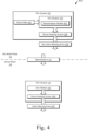
Fig. 4 is anexample illustration 400 of example data flows and actions during thepre-active phase 112, theactive phase 116, and the transition therebetween. Theillustration 400 starts with theESA system 102 in thepre-active phase 112. While in thepre-active phase 112, thesensor data 302 is received by theESA module 304. Thesensor data 302 may be received by adetermination module 402 that monitors thesensor data 302 to determine if thedetermination 114 should be made. - Based on the
sensor data 302, thedetermination module 402 makes thedetermination 114 that the collision with theobject 108 is imminent. Although shown as outputting thepre-active steering force 230, as discussed above, the determination may be made prior to getting to the pre-active steering force, for example, during the firstpre-active sub-phase 224. Based on making thedetermination 114, theESA system 102 transitions to theactive phase 116. - In some scenarios, the
determination 114 may not be made. For example, while in thepre-active phase 112, the driver may steer enough to avoid theobject 108, and thus, never trigger the determination. In this case, theESA system 102 may return to theinactive phase 106. Because thepre-active phase 112 is barely noticeable by the driver, entering and exiting thepre-active phase 112 without transitioning to theactive phase 116 is minorly disrupting to a driver, if at all. - While in the
active phase 116, theESA module 304 communicates with the power-steeringsystem 308. The communication causes the power-steeringsystem 308 to provide theactive steering force 232, which is effective to avoid the collision with theobject 108. -
Fig. 5 illustrates, at 500, an example of theESA system 102 in which ESA with thepre-active phase 112 can be implemented. Although thevehicle 104 is illustrated as a car, thevehicle 104 may comprise any vehicle (e.g., a truck, a bus, a boat, a plane, etc.) without departing from the scope of this disclosure. As shown underneath, theESA system 102 of thevehicle 104 includes at least oneprocessor 502, at least one computer-readable storage medium 504, one ormore sensors 506, the power-steeringsystem 308, theESA module 304, and optionally a third-party ESA component 508. - The processor 502 (e.g., an application processor, microprocessor, digital-signal processor (DSP), or controller) executes instructions 510 (e.g., code) stored within the computer-readable storage medium 504 (e.g., a non-transitory storage devices such as a hard drive, SSD, flash memory, read-only memory (ROM), EPROM, or EEPROM) to cause the
ESA system 102 to perform the techniques described herein. Theinstructions 510 may be part of an operating system and/or one or more applications of theESA system 102. - The
instructions 510 cause theESA system 102 to act upon (e.g., create, receive, modify, delete, transmit, or display) data 512 (e.g., application data, module data; sensor data, or I/O data). Although shown as being within the computer-readable storage medium 504, portions of thedata 512 may be within a random-access memory (RAM) or a cache of the ESA system 102 (not shown). Furthermore, theinstructions 510 and/or thedata 512 may be remote to theESA system 102. - The ESA module 304 (or portions thereof) may be comprised by the computer-
readable storage medium 504 or be a stand-alone component (e.g., executed in dedicated hardware in communication with theprocessor 502 and computer-readable storage medium 504). For example, theinstructions 510 may cause theprocessor 502 to implement or otherwise cause theESA module 304 to receive thesensor data 302 and transition between the phases, as described in regard toFigs. 1-4 . - The
sensors 506, which provide thesensor data 302, may be any type of sensors, detectors, or code. For example, thesensors 506 may comprise a ranging sensor to detect a range and/or location of theobject 108. Thesensors 506 may also comprise a potentiometer on a steering column of the vehicle to determine a steering input or rapid input by the driver. Furthermore, thesensors 506 may comprise code that determines if functions or components of the vehicle are active, e.g., the FCW being activated or not. - The power-steering
system 308 may be any type of system known by those of ordinary skill in the art. For example, the power-steering system may be hydraulic or electric, with column, rack, or steering-box-mounted actuators. Regardless of implementation, the power-steeringsystem 308 provides steering forces to the vehicle, which may be driver-initiated or initiated by theESA module 304. - The optional third-
party ESA component 508 is representative of an original equipment manufacturer (OEM) or third-party ESA component (e.g., hardware, software, system, or function). For example, theESA module 304 may interface with the third-party ESA component 508 to cause the power-steeringsystem 308 to apply theESA steering force 214. For example, theESA module 304 may make theprediction 110 and cause the third-party ESA component 508 to activate. By doing so, theESA module 304 may cause the third-party ESA component 508 to initiate thedrop 226 and thepre-active steering force 230. Similarly, the third-party ESA component 508 may make the determination and initiate theactive steering force 232. Without theESA module 304 communicating with the third-party ESA component 508, the third-party ESA component 508 would wait until thedetermination 114 to activate, thus causing thedrop 226 to occur after thedetermination 114, which, as discussed above, is not optimal. -
Fig. 6 illustrates anexample method 600 for ESA with thepre-active phase 112.Method 600 may be implemented utilizing the previously described examples, such as theprocess flow 100, theillustrations ESA system 102.Operations 602 through 612 may be performed by one or more entities (e.g., theESA system 102, theESA module 304, or the third-party ESA component 508). The order in which the operations are shown and/or described is not intended to be construed as a limitation, and any number or combination of the operations can be combined in any order to implement themethod 600 or an alternate method. - The
method 600 generally starts in an inactive state (e.g., the inactive state 106). At 602, a state or an environment of a vehicle at a first time is determined, and a prediction is made that a collision with an object is imminent. For example, theESA module 304 may receive thesensor data 302 and make theprediction 110. - At 604, a pre-active phase is entered based on the prediction that the collision with the object is imminent. For example, the
ESA module 304 may cause theESA system 102 to enter thepre-active phase 112. In some implementations, the third-party ESA component 508 may be activated (but not tasked to provide evasive steering). - At 606, a steering force provided by a power-steering system is adjusted. For example, the
ESA module 304 may cause the power-steeringsystem 308 to output thedrop 226 in theESA steering force 214 and thepre-active steering force 230. In some implementations, thedrop 226 and the pre-active steering force 130 are implemented via the third-party ESA component 508. - At 608, the state or the environment of the vehicle at a second time is determined, and a determination is made that the collision with the object is imminent. For example, the
ESA module 304 or the third-party ESA component 508 may receive thesensor data 302 and make thedetermination 114. - At 610, an active phase is entered based on the determination that the collision with the object is imminent. For example, the
ESA module 304 may cause theESA system 102 to enter theactive phase 116. In some implementations, theactive phase 116 enables the third-party ESA component 508 to provide evasive steering. - At 612, the steering force provided by the power-steering system is adjusted effective to steer the vehicle to avoid the collision with the object. For example, the
ESA module 304 may cause the power-steeringsystem 308 to output theactive steering force 232. Alternatively, the third-party ESA component 508 may cause the power-steeringsystem 308 to output theactive steering force 232. - Although implementations of ESA with a pre-active phase have been described in language specific to certain features and/or methods, the subject of the appended claims is not necessarily limited to the specific features or methods described. Rather, the specific features and methods are disclosed as example implementations for ESA with a pre-active phase.
Claims (11)
- A method of evasive steering assist (ESA) performed by a vehicle (104), the method comprising:determining, based on sensor data (302) received from one or more sensors that are local to the vehicle (104), at least one of a state or an environment of the vehicle (104) over time, the sensor data (302) comprising steering input by a driver of the vehicle (104);predicting, based on the state or the environment of the vehicle (104) at a first time, that a collision between the vehicle (104) and an object (108) is imminent;entering, based on the prediction that the collision with the object (108) is imminent, a pre-active phase (112);causing, during the pre-active phase (112), a power-steering system (308) to adjust a steering force (214) provided by the power-steering system (308) to supplement a driver steering force (216) by:causing, during a first pre-active sub-phase (224) of the pre-active phase (112), the steering force (214) to be zero; andcausing, during a second pre-active sub-phase (228) of the pre-active phase (112), the steering force (214) to be similar to that of an inactive phase (106) or higher than that of the inactive phase (106);determining, based on the state or the environment of the vehicle (104) at a second time indicating that a steering angle of the vehicle (104) at the second time is insufficient to avoid the collision, that the collision between the vehicle (104) and the object (108) is imminent;entering, based on the determination that the collision with the object (108) is imminent, an active phase (116); andcausing, during the active phase (116), the power-steering system (308) to adjust the steering force (214) supplementing the driver steering force (216) effective to steer the vehicle (104) to avoid the collision with the object (108).
- The method of claim 1, wherein a difference between the steering force (214) caused by the second pre-active sub-phase (228) and that of the inactive phase (106) corresponds to less than five Newton-meters (Nm) at a steering wheel of the vehicle (104).
- The method of claim 1 or 2, wherein the inactive phase (106) corresponds to a normal power steering mode of the vehicle (104).
- The method of any preceding claim, wherein:the entering the pre-active phase (112) comprises activating a third-party ESA component (508) of the vehicle (104); andthe causing the power-steering system (308) to adjust the steering force (214) during the pre-active phase (112) is performed via the third-party ESA component (508).
- The method of claim 4, wherein the determination that the collision with the object (108) is imminent and the causing the power-steering system (308) to adjust the steering force (214) during the active phase (116) are performed via the third-party ESA component (508).
- The method of any preceding claim, wherein the state or the environment of the vehicle (104) at the first time indicates a forward collision warning (FCW).
- The method of claim 6, wherein the state or the environment of the vehicle (104) at the first time further indicates a rapid steering action performed by a driver of the vehicle (104).
- The method of any preceding claim, wherein the steering angle of the vehicle (104) comprises an angle of one or more wheels used for steering the vehicle (104) or an angle of a steering wheel of the vehicle (104).
- The method of any of claims 4 or 8, wherein the causing the power-steering system (308) to adjust the steering force (214) comprises causing an increase in the steering angle of the vehicle (104).
- The method of any preceding claim, wherein the collision is a front collision.
- A system (102) for evasive steering assist (ESA) of a vehicle (104), the system (102) comprising:one or more sensors configured to produce sensor data (302) indicating at least one of a state of the vehicle (104) over time or an environment of the vehicle (104) over time;a power-steering system (308) configured to provide a steering force (214) to the vehicle (104);at least one processor (502); andat least one computer-readable storage medium (504) comprising instructions that, when executed by the processor (502), cause the system (102) to perform any of the methods of claims 1-10.
Applications Claiming Priority (1)
| Application Number | Priority Date | Filing Date | Title |
|---|---|---|---|
| US17/127,836 US11427254B2 (en) | 2020-12-18 | 2020-12-18 | Evasive steering assist with a pre-active phase |
Publications (2)
| Publication Number | Publication Date |
|---|---|
| EP4015351A1 EP4015351A1 (en) | 2022-06-22 |
| EP4015351B1 true EP4015351B1 (en) | 2025-07-09 |
Family
ID=78413668
Family Applications (1)
| Application Number | Title | Priority Date | Filing Date |
|---|---|---|---|
| EP21204761.7A Active EP4015351B1 (en) | 2020-12-18 | 2021-10-26 | Evasive steering assist with a pre-active phase |
Country Status (3)
| Country | Link |
|---|---|
| US (2) | US11427254B2 (en) |
| EP (1) | EP4015351B1 (en) |
| CN (2) | CN119329609A (en) |
Families Citing this family (1)
| Publication number | Priority date | Publication date | Assignee | Title |
|---|---|---|---|---|
| US12091084B2 (en) * | 2021-04-28 | 2024-09-17 | Aptiv Technologies AG | System and method of providing evasive steering assist |
Family Cites Families (25)
| Publication number | Priority date | Publication date | Assignee | Title |
|---|---|---|---|---|
| JP3574235B2 (en) * | 1995-08-31 | 2004-10-06 | 本田技研工業株式会社 | Vehicle steering force correction device |
| JP2003341501A (en) * | 2002-05-23 | 2003-12-03 | Masato Abe | Driving support control system |
| US6915196B2 (en) * | 2003-09-23 | 2005-07-05 | Ford Global Technologies, Llc | Method for operating a vehicle crash safety system in a vehicle having a pre-crash sensing system and countermeasure systems |
| DE102005002760B4 (en) * | 2004-01-20 | 2018-05-24 | Volkswagen Ag | Device and method for accident prevention in motor vehicles |
| JP2005254835A (en) * | 2004-03-09 | 2005-09-22 | Hitachi Ltd | Vehicle travel control device and vehicle control unit |
| DE102005003274A1 (en) * | 2005-01-25 | 2006-07-27 | Robert Bosch Gmbh | Collision occurrence preventing or reducing method for use in vehicle, involves identifying obstacle using field sensor, determining data of obstacle, and determining vehicle deceleration based on the data of obstacle and data of vehicle |
| US8139109B2 (en) | 2006-06-19 | 2012-03-20 | Oshkosh Corporation | Vision system for an autonomous vehicle |
| DE102011080789B4 (en) * | 2010-08-10 | 2022-11-10 | Continental Automotive Technologies GmbH | Process and system for controlling driving stability |
| KR101786542B1 (en) * | 2011-06-10 | 2017-11-16 | 현대모비스 주식회사 | Collision avoidance method for vehicles |
| US20130030651A1 (en) * | 2011-07-25 | 2013-01-31 | GM Global Technology Operations LLC | Collision avoidance maneuver through differential braking |
| US9558667B2 (en) * | 2012-07-09 | 2017-01-31 | Elwha Llc | Systems and methods for cooperative collision detection |
| DE102013009252A1 (en) * | 2013-06-03 | 2014-12-04 | Trw Automotive Gmbh | Control unit and method for an emergency steering assist function |
| DE102013009424A1 (en) * | 2013-06-04 | 2014-12-04 | Volkswagen Aktiengesellschaft | Emergency assistance without activated lateral guidance assistance |
| DE102014200826B4 (en) * | 2014-01-17 | 2024-07-25 | Volkswagen Aktiengesellschaft | System, functional unit and method for detecting a collision of a means of transport |
| CN103921791B (en) * | 2014-04-23 | 2016-08-17 | 上海扬梓投资管理有限公司 | Vehicle collision avoidance safety alarm method and device |
| CN104210489B (en) * | 2014-09-16 | 2017-06-13 | 武汉理工大学 | Vehicle and pedestrian impact bypassing method and system under bus or train route cooperative surroundings |
| JP6481520B2 (en) * | 2015-06-05 | 2019-03-13 | トヨタ自動車株式会社 | Vehicle collision avoidance support device |
| DE102016210848A1 (en) * | 2015-07-06 | 2017-01-12 | Ford Global Technologies, Llc | Method for avoiding a collision of a vehicle with an object, and driving assistance system |
| DE102015016531A1 (en) * | 2015-12-18 | 2017-06-22 | Adam Opel Ag | Driver assistance system and method for collision avoidance |
| DE102016109856A1 (en) * | 2016-05-30 | 2017-11-30 | Valeo Schalter Und Sensoren Gmbh | Method for avoiding a collision of a motor vehicle with an object based on a maximum predefinable wheel steering angle, driver assistance system and motor vehicle |
| US10606276B2 (en) * | 2016-09-30 | 2020-03-31 | Faraday & Future Inc. | User data-based autonomous vehicle system |
| JP7032178B2 (en) | 2018-03-02 | 2022-03-08 | トヨタ自動車株式会社 | Vehicle control device |
| JP7152165B2 (en) * | 2018-03-02 | 2022-10-12 | トヨタ自動車株式会社 | vehicle controller |
| EP3597510B1 (en) * | 2018-07-19 | 2021-03-17 | Volvo Car Corporation | Method and system for providing an intervening steering action for a host vehicle to avoid a collision |
| KR102676237B1 (en) * | 2018-10-26 | 2024-06-19 | 현대자동차주식회사 | Method and apparatus for Pre-safe sheet control |
-
2020
- 2020-12-18 US US17/127,836 patent/US11427254B2/en active Active
-
2021
- 2021-10-26 EP EP21204761.7A patent/EP4015351B1/en active Active
- 2021-12-16 CN CN202411475162.0A patent/CN119329609A/en active Pending
- 2021-12-16 CN CN202111544859.5A patent/CN114644040B/en active Active
-
2022
- 2022-06-28 US US17/809,469 patent/US11667330B2/en active Active
Also Published As
| Publication number | Publication date |
|---|---|
| CN119329609A (en) | 2025-01-21 |
| US11667330B2 (en) | 2023-06-06 |
| CN114644040B (en) | 2024-10-18 |
| EP4015351A1 (en) | 2022-06-22 |
| US20220194471A1 (en) | 2022-06-23 |
| US11427254B2 (en) | 2022-08-30 |
| US20220324513A1 (en) | 2022-10-13 |
| CN114644040A (en) | 2022-06-21 |
Similar Documents
| Publication | Publication Date | Title |
|---|---|---|
| US8392062B2 (en) | Method and device for avoiding and/or reducing the consequences of collisions upon evasion with respect to obstacles | |
| EP1982898B1 (en) | Steering assist system and vehicle mounted with the same | |
| US8401736B2 (en) | Driving assistance apparatus and driving assistance method | |
| US10286909B2 (en) | Method and apparatus for the closed-loop and/or open-loop control of a lateral guidance of a vehicle with the aid of a lane-keeping assist, and lane-keeping assist | |
| US10875569B2 (en) | Steering arbitration apparatus and method of vehicle, and steering arbitration system having the same | |
| US11214300B2 (en) | System and method for operating a motor vehicle | |
| US12233893B2 (en) | Pedal system for a vehicle designed to be driven in an at least partly automated manner | |
| JP4379793B2 (en) | Electronic control device for vehicle | |
| US20110279254A1 (en) | Method and device for carrying out an avoidance maneuver | |
| CN105050884B (en) | Collision avoidance assistance device and collision avoidance assistance method | |
| CN103029703A (en) | Lane-change assistance system of vehicle and lane-change assistance method thereof | |
| CN110371116A (en) | Device and method for controlling the driving of vehicle | |
| US20180154924A1 (en) | Method for Steering a Vehicle | |
| EP3495241B1 (en) | Assisting force control device and assisting force control method | |
| CN113460043A (en) | Method and system for determining available distance in front of vehicle | |
| US12397760B2 (en) | Driving assistance apparatus, driving assistance method, and driving assistance program | |
| JP5328738B2 (en) | Rear side steering assist technology | |
| EP4015351B1 (en) | Evasive steering assist with a pre-active phase | |
| JP2009101809A (en) | Vehicle driving support device | |
| EP4414234B1 (en) | Method and apparatus for collision avoidance or impact force reduction | |
| EP3617021B1 (en) | Performing a merging maneuver of an automated vehicle | |
| JP2017202774A (en) | Drive support method and drive support apparatus | |
| JP2007168641A (en) | Variable steering angle steering device and method, and automobile equipped with the variable steering angle steering device | |
| US12600353B2 (en) | Lane departure suppression device and lane departure suppression method | |
| KR101364391B1 (en) | Steer assist drive method and system using parking aid sensors |
Legal Events
| Date | Code | Title | Description |
|---|---|---|---|
| PUAI | Public reference made under article 153(3) epc to a published international application that has entered the european phase |
Free format text: ORIGINAL CODE: 0009012 |
|
| STAA | Information on the status of an ep patent application or granted ep patent |
Free format text: STATUS: THE APPLICATION HAS BEEN PUBLISHED |
|
| AK | Designated contracting states |
Kind code of ref document: A1 Designated state(s): AL AT BE BG CH CY CZ DE DK EE ES FI FR GB GR HR HU IE IS IT LI LT LU LV MC MK MT NL NO PL PT RO RS SE SI SK SM TR |
|
| STAA | Information on the status of an ep patent application or granted ep patent |
Free format text: STATUS: REQUEST FOR EXAMINATION WAS MADE |
|
| 17P | Request for examination filed |
Effective date: 20220908 |
|
| RBV | Designated contracting states (corrected) |
Designated state(s): AL AT BE BG CH CY CZ DE DK EE ES FI FR GB GR HR HU IE IS IT LI LT LU LV MC MK MT NL NO PL PT RO RS SE SI SK SM TR |
|
| STAA | Information on the status of an ep patent application or granted ep patent |
Free format text: STATUS: EXAMINATION IS IN PROGRESS |
|
| 17Q | First examination report despatched |
Effective date: 20221130 |
|
| RAP1 | Party data changed (applicant data changed or rights of an application transferred) |
Owner name: APTIV TECHNOLOGIES AG |
|
| RAP3 | Party data changed (applicant data changed or rights of an application transferred) |
Owner name: APTIV TECHNOLOGIES AG |
|
| GRAP | Despatch of communication of intention to grant a patent |
Free format text: ORIGINAL CODE: EPIDOSNIGR1 |
|
| STAA | Information on the status of an ep patent application or granted ep patent |
Free format text: STATUS: GRANT OF PATENT IS INTENDED |
|
| RIC1 | Information provided on ipc code assigned before grant |
Ipc: B60W 10/20 20060101ALI20250114BHEP Ipc: B60W 30/095 20120101ALI20250114BHEP Ipc: B60W 30/085 20120101ALI20250114BHEP Ipc: B60W 30/09 20120101ALI20250114BHEP Ipc: G05D 1/00 20060101ALI20250114BHEP Ipc: B62D 15/02 20060101AFI20250114BHEP |
|
| INTG | Intention to grant announced |
Effective date: 20250212 |
|
| GRAS | Grant fee paid |
Free format text: ORIGINAL CODE: EPIDOSNIGR3 |
|
| GRAA | (expected) grant |
Free format text: ORIGINAL CODE: 0009210 |
|
| STAA | Information on the status of an ep patent application or granted ep patent |
Free format text: STATUS: THE PATENT HAS BEEN GRANTED |
|
| P01 | Opt-out of the competence of the unified patent court (upc) registered |
Free format text: CASE NUMBER: APP_22150/2025 Effective date: 20250509 |
|
| AK | Designated contracting states |
Kind code of ref document: B1 Designated state(s): AL AT BE BG CH CY CZ DE DK EE ES FI FR GB GR HR HU IE IS IT LI LT LU LV MC MK MT NL NO PL PT RO RS SE SI SK SM TR |
|
| REG | Reference to a national code |
Ref country code: GB Ref legal event code: FG4D |
|
| REG | Reference to a national code |
Ref country code: CH Ref legal event code: EP |
|
| REG | Reference to a national code |
Ref country code: IE Ref legal event code: FG4D |
|
| REG | Reference to a national code |
Ref country code: DE Ref legal event code: R096 Ref document number: 602021033697 Country of ref document: DE |
|
| REG | Reference to a national code |
Ref country code: NL Ref legal event code: MP Effective date: 20250709 |
|
| PG25 | Lapsed in a contracting state [announced via postgrant information from national office to epo] |
Ref country code: PT Free format text: LAPSE BECAUSE OF FAILURE TO SUBMIT A TRANSLATION OF THE DESCRIPTION OR TO PAY THE FEE WITHIN THE PRESCRIBED TIME-LIMIT Effective date: 20251110 |
|
| PG25 | Lapsed in a contracting state [announced via postgrant information from national office to epo] |
Ref country code: NL Free format text: LAPSE BECAUSE OF FAILURE TO SUBMIT A TRANSLATION OF THE DESCRIPTION OR TO PAY THE FEE WITHIN THE PRESCRIBED TIME-LIMIT Effective date: 20250709 |
|
| REG | Reference to a national code |
Ref country code: AT Ref legal event code: MK05 Ref document number: 1811626 Country of ref document: AT Kind code of ref document: T Effective date: 20250709 |
|
| PG25 | Lapsed in a contracting state [announced via postgrant information from national office to epo] |
Ref country code: IS Free format text: LAPSE BECAUSE OF FAILURE TO SUBMIT A TRANSLATION OF THE DESCRIPTION OR TO PAY THE FEE WITHIN THE PRESCRIBED TIME-LIMIT Effective date: 20251109 |
|
| PGFP | Annual fee paid to national office [announced via postgrant information from national office to epo] |
Ref country code: DE Payment date: 20250917 Year of fee payment: 5 |
|
| PGFP | Annual fee paid to national office [announced via postgrant information from national office to epo] |
Ref country code: GB Payment date: 20251015 Year of fee payment: 5 |
|
| PG25 | Lapsed in a contracting state [announced via postgrant information from national office to epo] |
Ref country code: NO Free format text: LAPSE BECAUSE OF FAILURE TO SUBMIT A TRANSLATION OF THE DESCRIPTION OR TO PAY THE FEE WITHIN THE PRESCRIBED TIME-LIMIT Effective date: 20251009 |
|
| REG | Reference to a national code |
Ref country code: LT Ref legal event code: MG9D |
|
| PG25 | Lapsed in a contracting state [announced via postgrant information from national office to epo] |
Ref country code: AT Free format text: LAPSE BECAUSE OF FAILURE TO SUBMIT A TRANSLATION OF THE DESCRIPTION OR TO PAY THE FEE WITHIN THE PRESCRIBED TIME-LIMIT Effective date: 20250709 |
|
| PG25 | Lapsed in a contracting state [announced via postgrant information from national office to epo] |
Ref country code: FI Free format text: LAPSE BECAUSE OF FAILURE TO SUBMIT A TRANSLATION OF THE DESCRIPTION OR TO PAY THE FEE WITHIN THE PRESCRIBED TIME-LIMIT Effective date: 20250709 |
|
| PG25 | Lapsed in a contracting state [announced via postgrant information from national office to epo] |
Ref country code: HR Free format text: LAPSE BECAUSE OF FAILURE TO SUBMIT A TRANSLATION OF THE DESCRIPTION OR TO PAY THE FEE WITHIN THE PRESCRIBED TIME-LIMIT Effective date: 20250709 |
|
| PGFP | Annual fee paid to national office [announced via postgrant information from national office to epo] |
Ref country code: FR Payment date: 20251014 Year of fee payment: 5 |
|
| PG25 | Lapsed in a contracting state [announced via postgrant information from national office to epo] |
Ref country code: GR Free format text: LAPSE BECAUSE OF FAILURE TO SUBMIT A TRANSLATION OF THE DESCRIPTION OR TO PAY THE FEE WITHIN THE PRESCRIBED TIME-LIMIT Effective date: 20251010 |
|
| PG25 | Lapsed in a contracting state [announced via postgrant information from national office to epo] |
Ref country code: SE Free format text: LAPSE BECAUSE OF FAILURE TO SUBMIT A TRANSLATION OF THE DESCRIPTION OR TO PAY THE FEE WITHIN THE PRESCRIBED TIME-LIMIT Effective date: 20250709 |
|
| PG25 | Lapsed in a contracting state [announced via postgrant information from national office to epo] |
Ref country code: LV Free format text: LAPSE BECAUSE OF FAILURE TO SUBMIT A TRANSLATION OF THE DESCRIPTION OR TO PAY THE FEE WITHIN THE PRESCRIBED TIME-LIMIT Effective date: 20250709 |
|
| PG25 | Lapsed in a contracting state [announced via postgrant information from national office to epo] |
Ref country code: BG Free format text: LAPSE BECAUSE OF FAILURE TO SUBMIT A TRANSLATION OF THE DESCRIPTION OR TO PAY THE FEE WITHIN THE PRESCRIBED TIME-LIMIT Effective date: 20250709 Ref country code: PL Free format text: LAPSE BECAUSE OF FAILURE TO SUBMIT A TRANSLATION OF THE DESCRIPTION OR TO PAY THE FEE WITHIN THE PRESCRIBED TIME-LIMIT Effective date: 20250709 |
|
| PG25 | Lapsed in a contracting state [announced via postgrant information from national office to epo] |
Ref country code: RS Free format text: LAPSE BECAUSE OF FAILURE TO SUBMIT A TRANSLATION OF THE DESCRIPTION OR TO PAY THE FEE WITHIN THE PRESCRIBED TIME-LIMIT Effective date: 20251009 |
|
| PG25 | Lapsed in a contracting state [announced via postgrant information from national office to epo] |
Ref country code: ES Free format text: LAPSE BECAUSE OF FAILURE TO SUBMIT A TRANSLATION OF THE DESCRIPTION OR TO PAY THE FEE WITHIN THE PRESCRIBED TIME-LIMIT Effective date: 20250709 |
|
| PG25 | Lapsed in a contracting state [announced via postgrant information from national office to epo] |
Ref country code: RO Free format text: LAPSE BECAUSE OF FAILURE TO SUBMIT A TRANSLATION OF THE DESCRIPTION OR TO PAY THE FEE WITHIN THE PRESCRIBED TIME-LIMIT Effective date: 20250709 |
|
| PG25 | Lapsed in a contracting state [announced via postgrant information from national office to epo] |
Ref country code: SM Free format text: LAPSE BECAUSE OF FAILURE TO SUBMIT A TRANSLATION OF THE DESCRIPTION OR TO PAY THE FEE WITHIN THE PRESCRIBED TIME-LIMIT Effective date: 20250709 |
|
| PG25 | Lapsed in a contracting state [announced via postgrant information from national office to epo] |
Ref country code: DK Free format text: LAPSE BECAUSE OF FAILURE TO SUBMIT A TRANSLATION OF THE DESCRIPTION OR TO PAY THE FEE WITHIN THE PRESCRIBED TIME-LIMIT Effective date: 20250709 |
|
| PG25 | Lapsed in a contracting state [announced via postgrant information from national office to epo] |
Ref country code: IT Free format text: LAPSE BECAUSE OF FAILURE TO SUBMIT A TRANSLATION OF THE DESCRIPTION OR TO PAY THE FEE WITHIN THE PRESCRIBED TIME-LIMIT Effective date: 20250709 |
|
| PG25 | Lapsed in a contracting state [announced via postgrant information from national office to epo] |
Ref country code: CZ Free format text: LAPSE BECAUSE OF FAILURE TO SUBMIT A TRANSLATION OF THE DESCRIPTION OR TO PAY THE FEE WITHIN THE PRESCRIBED TIME-LIMIT Effective date: 20250709 |
|
| PG25 | Lapsed in a contracting state [announced via postgrant information from national office to epo] |
Ref country code: SK Free format text: LAPSE BECAUSE OF FAILURE TO SUBMIT A TRANSLATION OF THE DESCRIPTION OR TO PAY THE FEE WITHIN THE PRESCRIBED TIME-LIMIT Effective date: 20250709 Ref country code: EE Free format text: LAPSE BECAUSE OF FAILURE TO SUBMIT A TRANSLATION OF THE DESCRIPTION OR TO PAY THE FEE WITHIN THE PRESCRIBED TIME-LIMIT Effective date: 20250709 |